

KS Drechselbedarf STRATOS FU-230 Translation Of The Original Instruction Manual
FU-230
WOOD TURNING
LATHE
5 YEAR
WARRANTY

Drechselbedarf Schulte
- 2 -
Translation of the Original Instruction Manual Version 1.0
Dear Customer,
Thank you for choosing the Stratos Wood Turning Lathe.
The Stratos is a wood turning lathe that combines innovations with proven methods. The result of the
cooperation between experienced wood turners and engineers is a great value-for-money wood turning
lathe that is eminently suitable for beginners, advanced craftsmen, professionals and artists. Continuing
to support you is important to us. If you have any questions about our products or service, please call us
or send us an email.
We look forward to hearing from you. Your experiences enable us to keep improving the quality of this
wood turning lathe.
Kind regards
Drechselbedarf Schulte
D 49744 Geeste / Gr. Hesepe
Meppener Str. 111
Germany
Tel.: +49 (0) 59 37 / 91 32 34
Fax: +49 (0) 59 37 / 91 32 33
Homepage: www.drechselbedarf-schulte.de
Email: info@drechselbedarf-schulte.de
Note:
Based on the continual improvement process, the manufacturer reserves the right to make
alterations in the technical design at any time, without prior notice and without any manufacturer
liability.
Without explicit written permission, no part of this document must be reproduced or passed on, no matter
by which means.

Drechselbedarf Schulte
Translation of the Original Instruction Manual Version 1.0
- 3 -
Table of contents
Explanation of symbols .......................................................................................................... .- 4 -
Introduction..............................................................................................................................- 5 -
1. Basic health and safety notices......................................................................................- 5 -
2. Intended Use..................................................................................................................- 7 -
3. Technical data................................................................................................................- 8 -
Basic equipment...............................................................................................................................- 8 -
Optional accessory...........................................................................................................................- 8 -
4. Description of functions..................................................................................................- 9 -
5. Safety devices..............................................................................................................- 10 -
EMERGENCY STOP/OFF and ON Function..................................................................................- 10 -
Warning signs on the wood turning lathe........................................................................................ - 10 -
Overview of other safety devices....................................................................................................- 10 -
6. Installation site requirements .......................................................................................- 11 -
7. Assembling the wood turning lathe ..............................................................................- 12 -
Easy quick-release system (available as an option) ....................................................................... - 21 -
Assembling the bed extension (available as an option) .................................................................. - 22 -
7. Connecting the wood turning lathe to the mains supply...............................................- 23 -
8. Commissioning ............................................................................................................- 23 -
9. Using the wood turning lathe........................................................................................- 23 -
Headstock ...................................................................................................................................... - 23 -
Tailstock......................................................................................................................................... - 24 -
Tool rest ......................................................................................................................................... - 24 -
Locking device (excenter cleat) ...................................................................................................... - 25 -
Spindle lock.................................................................................................................................... - 25 -
24-position indexing ....................................................................................................................... - 25 -
Movable control unit and main switch ............................................................................................. - 26 -
Recommended speed range .......................................................................................................... - 27 -
Processing work pieces.................................................................................................................. - 30 -
Outrigger ........................................................................................................................................ - 33 -
10. Care and maintenance.................................................................................................- 35 -
11. Decommissioning.........................................................................................................- 35 -
12. Warranty conditions .....................................................................................................- 36 -
13. Troubleshooting guide .................................................................................................- 37 -
14. Appendices ..................................................................................................................- 38 -
Appendix 1 Declaration of Conformity ............................................................................................ - 38 -
Appendix 2 Spare parts lists..................................................................................................... - 39 -
Parts list A, Headstock................................................................................................................- 39 -
Drechselbedarf Schulte
- 4 -
Translation of the Original Instruction Manual Version 1.0
Parts list B, Lathe bed, tool rest, tailstock ....................................................................................- 42 -
Parts list C, Stand ....................................................................................................................... - 44 -
Appendix 3 Circuit diagram.............................................................................................................- 45 -
Appendix 4 Drilling template, auxiliary support (for cutting out/printing) .......................................... - 46 -
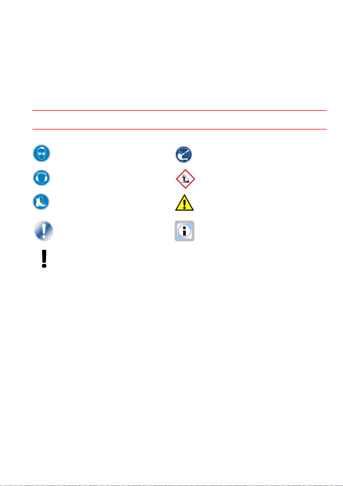
Explanation of symbols
Use eye protection Use breathing protection
Use hearing protection Environmentally hazardous substances
Use protective footwear Direct risk to health and serious injuries
Damage or risk to people, the lathe,
material or the environment
Information on the economical use of the
wood turning lathe
Important information

Drechselbedarf Schulte
Translation of the Original Instruction Manual Version 1.0
- 5 -
Introduction
This handbook contains instructions for assembly, safety notices, general operating and
maintenance instructions and spare parts lists. The design and construction of the Stratos 230
are intended to enable you to work with the machine without problems for many years, if you
comply with the recommendations specified in this manual.
1. Basic health and safety notices
Serious injuries can be caused by non-compliance with the following rules and warnings as
well as with the safety notices specified in this operating manual and on the machine itself.
In the interest of your own safety. Read the operating instructions before starting the
assembly and before commissioning the machine.
Store these operating instructions in a safe place and also pass them on if you hand over the wood
turning lathe to someone else.
Do not make technical changes. The machine has been designed for working exclusively
with wood.
Familiarize yourself with the applications and restrictions of the machine and associated risks. If the
machine is not used for its intended purpose, the vendor will not bear any direct or indirect warranty
claims. Furthermore, the vendor is not liable for injuries caused by the non-intended use of the
machine.
Get informed before the initial use of the machine.
If you are not familiar with the functions of a wood turning lathe, find competent help. We urgently
recommend an introduction to handling a wood turning lathe by an experienced person.
Drechselbedarf Schulte offers appropriate courses.
When young people are using the machine, the relevant legal requirements of the respective
country must be complied with.
Physical suitability. Users have to be physically fit and be introduced to the use of a wood turning
lathe by a competent person prior to initial use. Handicapped persons may use the machine only
after previous consultation by a specialist and with auxiliary resources, if applicable.
Keep children and visitors away from the work place.
Children and visitors must stay in a safe zone outside the working area. Make the working area childproof by locking the workshop and by disconnecting the supply line or making sure it can be isolated.
Wear suitable clothing.
There is a risk of injury from rotating parts. Wear tight-fitting clothing. Take off scarves,
rings, bracelets and other jewelry and garments that could get caught by the rotating parts.
Wear sturdy protective footwear and ensure the floor is non-slip. Wear headgear/a hair net
to protect long hair. Avoid wearing gloves which may be caught during the wood turning
process.
Use Personal Protective Equipment (PPE).
Hearing protection: For extended periods on the wood turning lathe, wear hearing
protection. Different materials can generate increased noise levels during wood turning.

Drechselbedarf Schulte
- 6 -
Translation of the Original Instruction Manual Version 1.0
Safety goggles/face mask: Always wear safety goggles when working with the machine.
Always use adequate eye/face protection. Conventional eyeglasses are generally only
shock-resistant and safety goggles only protect the eyes. Face protection protects the
eyes and the face.
Breathing protection: Different types of wood, exotic wood materials and other harmful
substances as well as tasks such as sanding, sawing and drilling can generate harmful
dust. Therefore, only ever operate the machine in well-ventilated rooms and wear
breathing protection (PPE). Also use suitable dust extraction and/or filtration of the circulating air.
If you are using the wood turning lathe commercially, statutory safety regulations of the respective
country must be complied with.
Do not work in a damp and dangerous environment.
The Stratos Wood Turning Lathe has been exclusively designed for use indoors.
Protect the wood turning lathe from damp and humid locations. Do not subject the machine to
moisture. Ensure the working environment is sufficiently lit and ventilated. Avoid areas with an
explosive atmosphere. Non-compliance with these rules can lead to loss of warranty.
Keep your work place clean.
Untidy work places and surfaces can cause accidents. Only after all objects (tools, pieces of wood
etc.) have been removed from the wood turning lathe, should you turn on the machine. Keep the
immediate working area and the floor free from dirt and offcuts. Accumulated wood chippings are a
fire risk and can cause accidents.
Fire prevention
Observe fire detection and fire fighting options such as location and operation of fire extinguishers.
Comply with electrical safety standards.
Pay attention to the appropriate electrical installation to which you connect the wood turning lathe
and only ever use the supplied safety plugs. Do not use extension leads.
The isolated sockets used must be fused with a 16 amp supply.
Disconnect the machine from the power supply before carrying out maintenance or repairs.
In the event of a power outage, the work piece will continue to spin freely. The machine slowing
down can take some time.
Prevent unintentional starting.
Make sure that the main switch is in the "OFF" position when connecting the wood turning lathe to
an isolated socket.
Never leave the machine running unsupervised.
Leave the machine only when it has been turned off and has come to a standstill.
Safety devices
Make sure the available safety devices are in their position and kept operational.
Use the appropriate tools.
Only ever use suitable tools or accessories for wood turning. Avoid unnecessary load on the tools.
Maintain the wood turning tools in a good condition. Sharp and clean tools help ensure the best and
safe results. This includes the correct position of the tool in relation to the work piece.
Never climb on the machine and tools.
A tilting machine or a cutting tool which is accidentally touched can cause serious injuries.
Remove adjusting wrenches and spanners.
Never leave the T-bar handle in the chuck. When starting the chuck, the T-bar handle can be
ejected and cause serious injuries. Get into the habit of checking that all tools have been removed
from the machine before turning it on.
Cleaning the wood turning lathe.
Turn off the wood turning lathe before cleaning it. Remove wood chippings and dirt with a brush.
Important: After green or wet turning, the lathe bed must be cleaned immediately!
Attention during work. Concentrate on your work. Distractions caused by conversations or
carelessness can cause serious injuries.

Drechselbedarf Schulte
Translation of the Original Instruction Manual Version 1.0
- 7 -
Always ensure the correct posture and your balance.
Do not use the machine if you are tired or under the influence of drugs, alcohol or medication.
Check for damaged parts.
Before using the wood turning lathe or tools, carefully check them for damage. Ensure that these
items are in an appropriate condition and that they are fit for purpose.
Check the alignment and attachment of moveable parts. Faulty parts can impact operation and
cause injuries. Damaged parts must be repaired or replaced by a professional.
Working with the wood turning lathe.
With the electric current turned off, check, by turning the spindle with your hand, that the work piece
can be rotated freely.
Check the work piece for parts that may break off it during the wood turning process. Remember
when using adhesives that cyanoacrylate super glue can remain liquid for hours in cavities or wide
splits. It can be thrown outward because of the centrifugal force and be ejected in the same direction
as the wood chippings, i.e. toward the wood turner, potentially causing injuries or representing a
health hazard.
Always check whether the correct speed is set before turning on the spindle.
Use the lowest speed for new work pieces or work pieces that are not round.
Turn using the recommended speed (Table in Fig. 49 and Fig. 50).
Never slow down the work piece with your hand.
Position the tool rest as close to the work piece as possible (about 5-10 mm). Before each start, turn
the work piece with your hand in order to ensure that it rotates freely. Use the handwheel for this.
Turn off the wood turning lathe every now and then in order to position the tool rest ideally.
2. Intended Use
The Stratos 230 Wood Turning Lathe has been designed and built for turning work using wood materials,
horn, bone and plastics in small sizes. Processing of other materials is not permitted or may only take
place in particular cases after feedback with the equipment manufacturer.
The wood turning lathe must exclusively be used for turning between centers and face plate turning of
round and regularly shaped, prismatic work pieces.
The wood turning lathe is not suitable for use in environments with a risk of explosion.
In the event of non-intended use of the machine, risk to people and material damage can result, as well
as the machine's function being compromised.
If the wood turning lathe is used for anything other than listed above, its use will be deemed as nonintentional. As the manufacturer, we will not accept any liability for damage caused in this way.

Drechselbedarf Schulte
- 8 -
Translation of the Original Instruction Manual Version 1.0
3. Technical data
Overall dimensions
Length x height x depth ........................................................................... 1,350 mm x 1,250 mm x 500 mm
Weight
Bench top (without cast iron stand) .................................................................................................. 113 kg
Stand ................................................................................................................................................. 65 kg
Total weight ..................................................................................................................................... 178 kg
Distance between centers ...........................................................................................................700 mm
Distance between centers with 400 mm bed extension ............................................................... 1,100 mm
Height of centers ..........................................................................................................................230 mm
Headstock
Spindle thread ...................................................................................................................... M33 x 3.5 mm
Bore ........................................ No. 2 Morse taper (MT2) with a through-hole of 15 mm through headstock
Index with viewing window .................................................24-position indexing (in 15 degree increments)
Spindle lock ...................................................................................................................................... 9-way
Sliding headstock pivots by 180 degrees with detent positions at 0, 22.5, 67.5, 90, 112.5 and 180
degrees
Power unit .................................... ~230 Volt, three-phase motor, IP54, 1,420 rpm, 50 Hz 1,500 W
...................................................... Variable speed control of the motor by the potentiometer on the movable control unit.
Mains supply ....................................................................................................230 Volt ~ 1/N/PE 50 Hz
Speed stages (rpm on the spindle) ................... Stage I 180 – 3,700 rpm and Stage II 80 – 1,350 rpm
............................................................................... by moving the Poly-V belt (reduction Level II 2.74: 1).
Tailstock
Bore ............................................................................... No. 2 Morse taper (MT2) with 9 mm through-hole
Quill travel ................................ ..................................................................................... 100 mm with scale
Tool rest ................................................................................................................. 350 mm with 1“ stems
Emission sound pressure level ................................................................ ................................... <79 dB
(A)
Outrigger optional with bed extension
Work piece diameter ............................................................................................................. max. 800 mm
Work piece thickness ............................................................................................................ max. 200 mm
Basic equipment
350 mm tool rest, 150 mm face plate, MT2 live center, 25 mm spur center, face plate wrench to
loosen the face plate, holder for tools and movable control unit, knock out bar and English language
operating manual.
Optional accessory
Outrigger and machine bed extension (400 mm) in one with extension stems for the tool rest. Cast
iron machine stand, prepared on three sides for outrigger.

Drechselbedarf Schulte
Translation of the Original Instruction Manual Version 1.0
- 9 -
Rating plate
Fig. 1
4. Description of functions
A wood turning lathe is a machine with which cylindrical or prismatic wooden work pieces are generally
processed. For this, work pieces are secured between headstock and tailstock using a drive center
(headstock) and live center (tailstock) or a particular clamping device (chuck, face plate) and driven via
an electric motor.
Drive is from an electric motor via pulleys to the spindle. Stratos has two speed stages (gear ratios) that
you can select. Fine-tuning of the speed takes place via frequency conversion which is regulated by a
potentiometer (POTI in short) on the movable control unit, so you can steplessly set the speed in the
respective speed stage. This will help you select the appropriate speed corresponding to the diameter
and the shape of the work piece. It will improve safety during wood turning and the quality of the work
piece surface.
In order to turn on the power unit, first turn the main switch (see Fig. 47) clockwise until it clicks into
place. On the movable control box (Fig. 2), switch on the motor and increase the speed on the
potentiometer.
Automatic deactivation
Stratos is equipped with a zero-voltage switch which deactivates the lathe in the event of a power outage
or when the pulley cover is lifted, and it prevents restarting when the power has been restored. The
speed can also be turned off via the frequency converter in the event of overload during wood turning. In
order to restore the wood turning lathe to operation in any case, the cause must be eliminated. In the
event of a power outage, power must be restored. If the cover has been lifted, it must be closed again. In
the event of overload, the load must be reduced or the pulley with a lower speed must be chosen.
Using the tool rest, the turning tools are manually moved toward the work piece. This poses a risk of
injury because the resulting cutting forces have to be countered by the user.
In order to compensate for the resulting forces, the turning tools must always rest firmly on the tool rest.
It is important that you read the operating instructions carefully before initial use in order to familiarize
yourself with the risks that can be created by the operation of the machine (in particular rotating parts,
resulting forces and risk of injury).
If you have no experience with wood turning, please get informed before working with the wood turning
lathe. In order to do this, ask someone with experience in wood turning and have them train you.
At our site, we are offering beginners' and advanced courses.
Drechselbedarf Schulte
- 10 -
Translation of the Original Instruction Manual Version 1.0
5. Safety devices
Danger!
The wood turning lathe must always be used with functioning safety devices. Turn off the lathe
immediately on noticing that a safety device is faulty or has been removed! All accessories added by
the user must be equipped with the specified safety devices.
The safety devices are for the protection of people and material property. Without intact safety devices,
severe injuries can be the consequence.
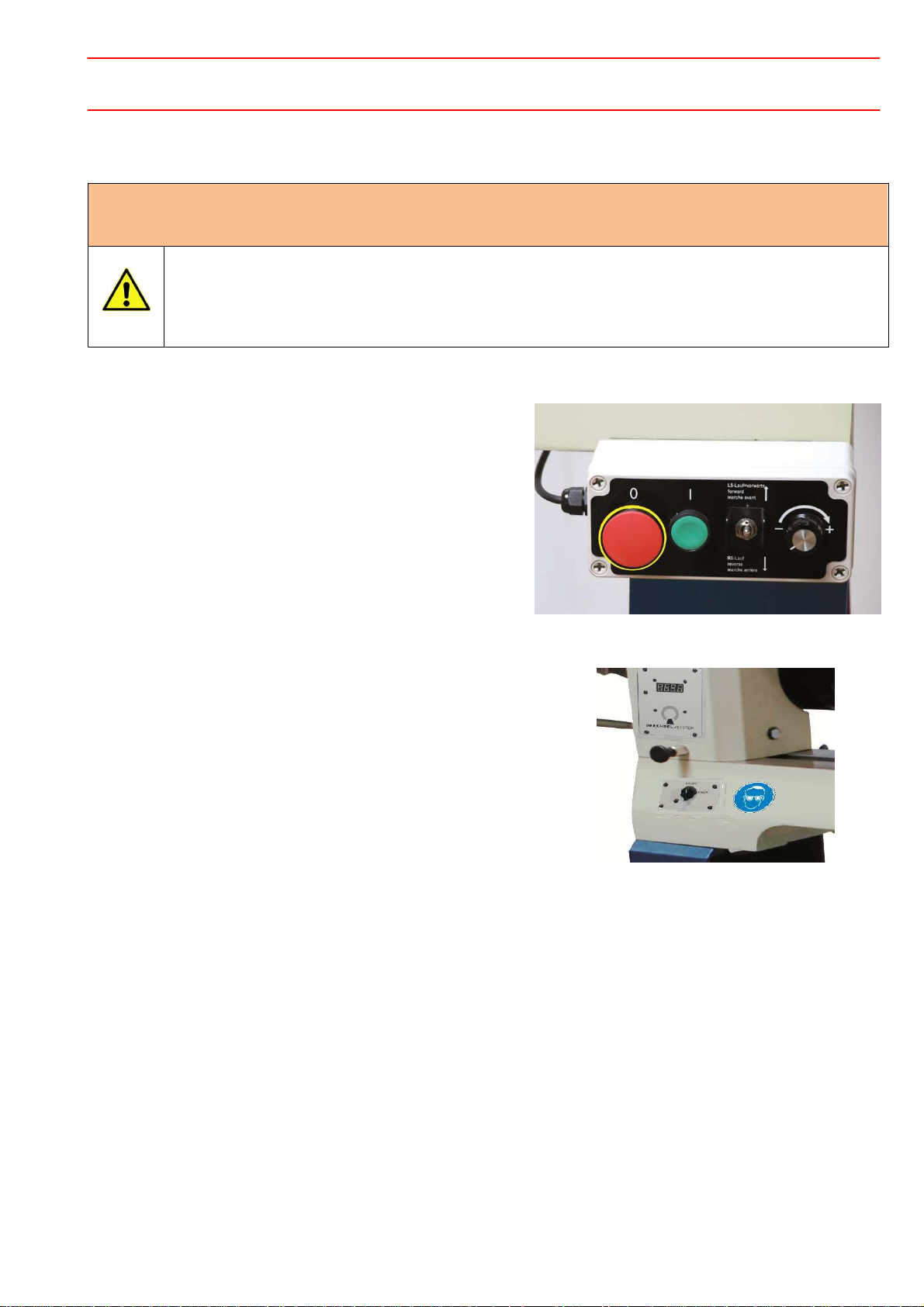
EMERGENCY STOP/OFF and ON Function
The lathe is equipped with a red combination switch (0)
with which it can be EMERGENCY STOPPED as well
as stopped in the conventional way (Fig. 2). By pressing
the red button (0), all machine functions are
deactivated.
To restart, press the green ON button (I).
The toggle switch is used to activate the machine's
reverse operation.
The potentiometer regulates the speed.
.
Warning signs on the wood turning lathe
The warning signs on the wood turning lathe are for your
safety. Always keep them legible and observe their meaning
(see Fig. 2a, Wear safety goggles).
Overview of other safety devices
The wood turning lathe is equipped with various safety devices:
Fig. 2
Fig. 2a
1. Electrical grounding conductor which is connected to the local mains supply via the safety plug.
2. Cover with interrupter switch over the pulley drive.
3. Electric motor cover.
4. Emergency stop via the movable control unit.
5. Stop rods on both lathe ends.

Drechselbedarf Schulte
- Translation of the Original Instruction Manual Version 1.0
- 11
6. Installation site requirements
Requirement Recommendation
Lathe installation site
Position the Stratos 230 close to a power source (isolated socket).
Ensure the floor is level, solid and stable.
Leave sufficient space around the machine. Also consider sufficient
space for when the headstock has been rotated, for the bed extension
and/or the outrigger. Other machines in the workshop must not interfere
with the lathe's operation.
Lighting and ventilation
Ensure adequate lighting (lighting intensity according to DIN 5035) and
ventilation. Also use adjustable lighting for your working area at the lathe
so no shadow is cast on the work piece. We recommend a light source
with a value of at least 300 LUX, or even better, 500 LUX at the cutting
edge of the tool.
If possible, position the machine close to a window.
Electrical equipment
To operate the wood turning lathe, a suitable, conventional 230 V
isolated socket fused with a 16 amp supply is required.
Electric cables and sockets must comply with local electricity regulations.
If in doubt, ask your electrical specialist. Avoid the use of an extension
cable (see Chapter "Connecting the wood turning lathe to the mains
supply").
Ventilation
Adequately ventilate your work place. The degree of ventilation depends
on the size of the workshop and the number of work pieces being
processed. The use of dust extractors and filters reduces health hazards.
Working height
Set up the working height of the wood turning lathe so the spindle center
is at the same level as the user's elbow.
Working area
When securing the lathe to the floor, free space around the lathe of at
least 80 cm is required for repairs and maintenance work.
Stand
If the lathe is used without a stand, the operator must choose a suitable
installation surface. In this case, the outrigger cannot be used.
/
7.
Assembling the wood turning lathe
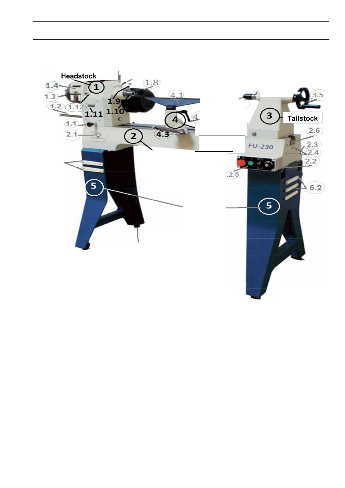
Description of the wood turning lathe
1.5
1.6
rt 1.7
,
5.2
Lathe bed
2
Tool rest support
1
Stand
ST AT •S
3.1
3.2
lj8)
- - - 5 . 1
Fin '.1
1 Headstock
1.1 Headstock pivot locking pin
1.2 Headstock clamping lever
1.3 Handwheel
1.4 Pulley cover
1.5 Rubber tray
1.6 Motor clamping lever
1.7 Quick-release lever for motor locking mechanism
1.8 Electric motor
1.9 Spindle locking pin
1.10 Spindle with M33 thread
1.11 Digital speed display
1.12 24-position locking pin
2 Lathe bed
2.1 Main switch
2.2 Movable control unit holder
2.3 Tool holder (rear)
2.4 Holes for outrigger bed extension
- 12 - Translation of the Original Instruction Manual Version 1.0
2.5 Movable control unit
2.6 Stop rod
3 Tailstock
3.1 Live center
3.2 Quill
3.3 Quill fine adjustment (on the rear)
3.4 Quick-release lever for quill locking mechanism
(on the rear)
3.5 Handwheel
4 Tool rest support
4.1 Tool rest
4.2 Quick-release lever
4.3 Tool rest support clamping lever
5 Stand
5.1 Level adjusting feet
5.2 Anchor points for bed extension
©
Drechselbedarf Schulte

-
Assembly information:
Warning!
Be aware of the weight of the individual components and handle them carefully to avoid
causing yourself any injuries.
Ensure that all bolted joints are tight but not over-tightened. Check all bolted joints for
tightness after eight operating hours.
During assembly, put the headstock down in such a way that the cable connections are not
damaged and the cables are not disconnected under any circumstances.
The cast iron stand was developed for use with the Stratos 230. Using it with other
machines can lead to injury.
B Stand
Accessories
B Stand
We carefully packaged the machine at our site. Upon receipt, please check the packaging for damage or
whether the machine has become damaged during transport as well as whether the contents are
complete. In the event of complaints, please report them to your supplier immediately and do not start
using the machine. Claims at a later stage will not be accepted. Using this machine with others can lead
to loss of warranty.
The packaging is made of raw material and can be returned to the raw materials cycle via the available
local collection sites. Dispose of the packaging material only when the wood turning lathe has been
assembled and is functioning properly.
Carefully read the operating manual beforehand!
Tool and resource recommendations for assembly:
To support the headstock, two timber bearers are needed.
14 mm wrench, Phillips screwdriver, Allen key for loosening the face plate from the spindle and the
mounting parts.
Commercially available spirit level.
Timber board (length x width) 1,150 x 100 mm and about 20 mm thickness with two holes of Ø 9 mm
according to the drilling template (see Appendix 4) to secure the stand during assembly.
A second person is essential during assembly.
Fig. 5 Accessories
Fig. 4 Delivery contents
Lathe bed, headstock, tailstock and tool rest support with tool rest are one unit.
The stand and the accessories are packaged in separate boxes (Fig. 4 and 5).
Drechselbedarf Schulte Translation of the Original Instruction Manual Version 1.0 - 13
Drechselbedarf Schulte
- 14 -
Translation of the Original Instruction Manual Version 1.0
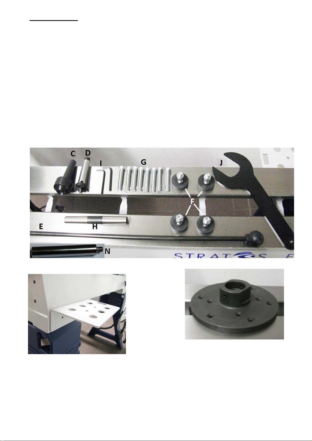
Delivery contents
K
L
A Lathe bed (see Fig. 15) with headstock, tailstock, tool rest support with tool rest 350 mm (1“ stems).
B Stand (see Fig. 10).
C Live center
D Spur center 25 mm, MT2.
E Knock out bar.
F Feet, height adjustable, 8 x 3/8“ x 50 mm (Fig. 12).
G Bolts 8 x 3/8“ for fixing the lathe bed to the stands.
H Morse taper double-sided, MT2, for aligning the centers.
I Allen keys 3 and 4 mm.
J Face plate wrench to loosen the face plate from the spindle.
K Face plate 150 mm with M33 x 3.5 mm thread with 2 set screws 5 mm (Fig. 8).
L Tool holder for the rear of the lathe bed (Fig. 7).
M Control unit holder for the front of the lathe bed (Fig. 11).
N In the accessory set, there is a stainless steel handle which has to be attached to the top of the motor
flange. It is used to loosen the Poly-V belt.
Fig. 6 Accessories
Fig. 8 Face plate with set screw
Fig. 7 Tool holder
 Loading...