

Page 1
Operating Instructions
Nº A1766.8E/2
Works Nº: ________________________________
Type series: ______________________________
precautionary notes. Please read the manual
thoroughly prior to installation of unit, connection to
the power supply and commissioning. It is
imperative to comply with all other operating
instructions referring to components of this unit.
These operating instructions contain
fundamental information and
KSB WKT
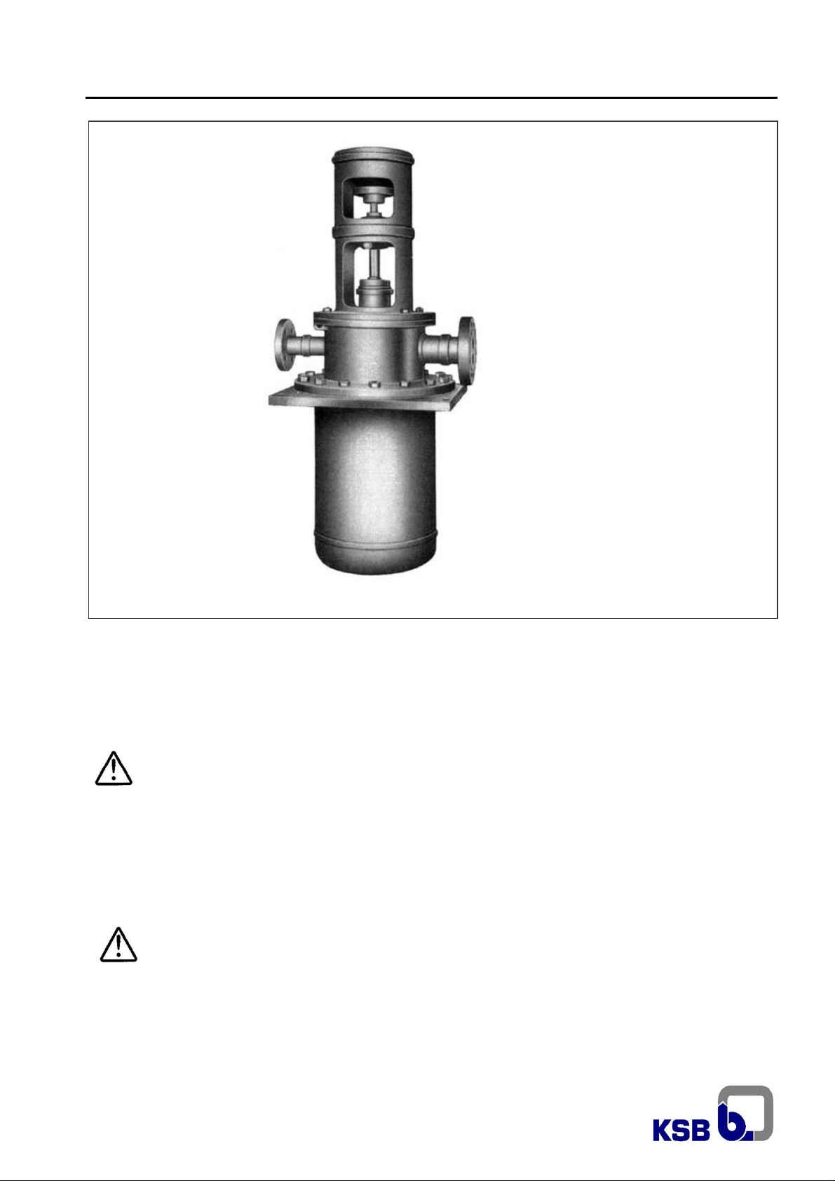
Vertical Process Pump
according to API 610
as per Directive 94/9/EC
This manual shall always be kept close to
the unit´s location of operation or directly
on the pump set.
Page 2

Contents
Page
1 General 4
2 Safety 4
2.1 Marking of Instructions in the manual 4
2.2 Personnel qualification and training 4
2.3 Non-compliance with safety instructions 4
2.4 Safety awareness 4
2.5 Safety instructions for the operator / user 5
2.6 Safety instructions for maintenance,
inspection and installation work
2.7 Unauthorized modification and manufacture
of spare parts
2.8 Unauthorized modes of operation 5
2.9 Explosion protection 5
2.9.1 Unit fill 5
2.9.2 Marking 5
2.9.3 Checking the direction of rotation 5
2.9.4 Pump operating mode 5
2.9.5 Temperature limits 6
2.9.6 Maintenance 6
3 Transport an d interim storage 6
3.1 Transport 6
3.2 Interim storage (indoors) / preservation 6
3.3 Devolution / discard 7
3.3.1 Devolution 7
3.3.2 Discard 7
4 Description of the product an
accessories
4.1 Technical specification 7
4.2 Designation 7
4.3 Design details 7
4.3.1 Pump casing 7
4.3.2 Impeller 7
4.3.3 Shaft seal 7
4.3.4 Bearing arrangement 8
4.3.5 Permissible forces and moments at the
discharge nozzle
4.3.6 Noise characteristics
4.4 Accessories
4.5 Dimensions and weights
5 Installation at site 10
5.1 Safety regulations
5.2 Checks to be carried out prior to installation 10
5.2.1 Place of installation 10
5.3 Foundation 10
5.4 Barrel cleaning
5.5 Mounting 10
5.6 Aligning the pump / drive
5.7 Connecting the piping
5.7.1 Auxiliary connections 11
5.7.2 Coupling guard 11
5.8 Final check 11
5.9 Connection to power supply 11
5
5
7
9
9
9
9
10
10
10
11
WKT
Page
6 Commissioning, start-up / shutdown 12
6.1 Preparations 12
6.1.1 Recommended safety instrumentation for
pump
6.1.2 Lubrication 12
6.1.3 Pre-comissioning checks 12
6.1.4 Lubrication 12
6.1.5 Shaft seal 13
6.1.6 Priming the pump and checks to be carried
out
6.1.7 Checking the direction of rotation 14
6.2 Start-up 14
6.2.1 Minimum flow 14
6.3 Shutdown
6.4 Operating limits 15
Temperature of the fluid handled, ambient
6.4.1
temperature, bearing temperature
6.4.2 Switching frequency 15
6.4.3 Density or fluid pumped 15
6.4.4 Abrasive fluids
6.4.5 Minimum / Maximum flow
6.5 Shutdown / storage / preservation
6.5.1 Storage of new pumps
Measures to be taken for prolonged
6.5.2
shutdown
6.6 Returning to service after storage
7 Servicing / Maintenance
7.1 General instructions
7.2 Servicing / inspection
7.2.1 Supervision of operation 16
7.2.2 Lubrication and lubricant change 17
7.3 Drainage / disposal 17
7.4 Dismantling 17
7.4.1 Fundamental instructions and
recommendations
7.4.2 Dismantling the pump 17
7.4.3 Examination of individual components 18
7.5 Reassembly 20
7.5.1 General instructions 20
7.5.2 Preparations 21
7.5.3 Tightening torques 24
7.6 Spare parts stock 24
7.6.1 Recommended spare parts stock for 2
years’ operation to DIN 24296
8 Troubleshooting 25
9 Sectional drawing 26
Supplementary sheet 28
Annex 01 29
12
13
15
15
15
15
16
16
16
16
16
16
16
17
24
Page 3
Introduction
KSB has supplied you an equipment that has been designed and manufactured with the latest technology.
Due to its simple and tough construction, it will need few maintenance. With the aim to provide our clients with a
satisfactory, trouble free operation, we recommend to install and care our equipment according to the instructions
contained in this service manual.
This manual has been prepared to inform the end user about construction and operati on of our pumps, describing the
proper procedures for handling and maintenance.
We recommend that this manual should be handled by the maintenance supervision.
This equipment must be used at operation conditions for which it has been selected, suc h as: flow rate, total head, speed,
voltage, frequency and temperature of pumped liquid.
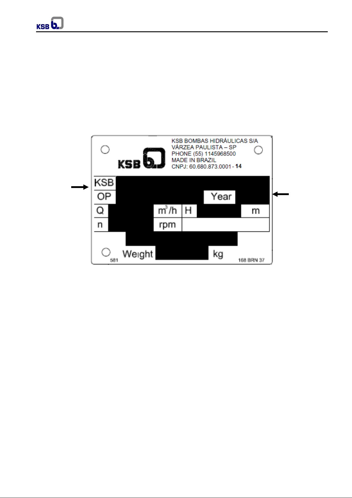
Place for description
of type and size of
the pump
WKT
Place for order
number
Fig. 01 - Nameplate
For requests about the equipment, or when ordering spare parts, please mention the t ype of the pump and
the Production Order number (serial nº). This information can be obtained from the nameplate of each
pump. If the nameplate is not available, the OP number is engraved in low relief o n the suction flange and
on the discharge flange you may find the impeller diameter.
Attention: This manual contains very important recommendations and instructions. Must be carefully read before
installation, electrical connection, first start up and maintenance.
3
Page 4
1. General
Caution
technology; it is manufactured with utmost care and
subject to continuous quality control.
These operating instructions are intended to facilitate
familiarization with the unit and its designated use.
The manual contains important information for reliable,
proper and efficient operation. Compliance with the
operating instructions is of vital importance to ensure
reliability and a long service life of the unit and to avoid
any risks.
These operating instructions do not take into account
local regulations; the operator must ensure that such
regulations are strictly observed by all, including the
personnel called in for installation.
This pump / unit must not be operated beyond
the limit values for the fluid handled, capacity,
speed, density, pressure, temperature and motor
rating specified in the technical documentation. Make
sure that operation is in accordance with the instructions
laid down in this manual or in the contract
documentation. Contact the manufacturer, if required.
The nameplate indicates the type series / size, main
operating data and works number; please quote this
information in all queries, repeat orders and particularly
when ordering spare parts.
If you need any additional information or instructions
exceeding the scope of this manual or in c ase of damage
please contact KSB´s nearest customer service centre.
For noise characteristics please refer to section 4.3.6.
This KSB product has been developed
in accordance with state-of-the-art
2. Safety
These operating instructions contain fundamental
information which must be complied with during
installation, operation, monitoring and maintenance.
Therefore this operating manual must be read and
understood both by the installing personnel and the
responsible trained personnel / operators prior to
installation and commissioning, and it must always be
kept close to the location of operation of the machine /
unit for easy access.
Not only must the general safety instructions laid down in
this chapter on “Safety” be complied with, but also the
safety instructions outlined under specific headings,
particularly if the pump / unit is operated in hazardous
areas (see section 2.9).
2.1 Marking of instructions in the manual
The safety instructions contained in this manual whose
non-observance might cause hazards to persons are
specially marked with the symbol
general hazard sign to ISO 7000-0434
the electrical danger warning sign is
safety sign to IEC 417-5036
WKT
and special instructions concerning explosion protection
are marked
The word
is used to introduce safety instructions whose nonobservance may lead to damage to the machine and its
functions.
Instructions attached directly to the machine, e.g.
- arrow indicating the direction of rotation
- markings for fluid connections
must always be complied with and be kept in a perfectly
legible condition at all times.
2.2 Personnel qualification and training
All personnel involved in the operation, maintenance,
inspection and installation of the unit must be fully
qualified to carry out the work involved.
Personnel responsibilities, competence and supervision
must be clearly defined by the operator. If the personnel
in question is not already in possession of the requisite
know-how, appropriate training and instruction must be
provided. If required, the operator may commission the
manufacturer / supplier to take care of such training. In
addition, the operator is responsible for ensuring that the
contents of the operating instructions are fully un derstood
by the responsible personnel.
2.3 Non-compliance with safety instructions
Non-compliance with safety instructions can jeopardize
the safety of personnel, the environment and the machine
/ unit itself. Non-compliance with these safety instructions
will also lead to forfeiture of any and all rights to claims for
damages.
In particular, non-compliance can, for example, result in:
- failure of important machine / system functions;
- failure of prescribed maintenance and servicing
practices;
- hazard to persons by electrical, mechanical and
chemical effects as well as explosion;
- hazard to the environment due to leakage of
hazardous substances.
2.4 Safety awareness
It is imperative to comply with the safety instructions
contained in this manual, the relevant national and
international explosion protection regulations, and the
operator´s own internal work, operation and safety
regulations.
Ex symbol relates to additional requirements
which must be adhered to when the pump is
operated in hazardous areas.
Caution
4
Page 5
2.5 Safety instructions for the operator / user
- Any hot or cold components that could pose a hazard
must be equipped with a guard by the operator.
- Guards which are fitted to prevent accidental contact
with moving parts (e.g. coupling) must not be
removed whilst the unit is operating.
- Leakages (e.g. at the shaft seal) of hazardous fluids
handled (e.g. explosive, toxic, hot) must be contained
so as to avoid any danger to persons or the
environment. All relevant laws must be heeded.
- Electrical hazards must be eliminated. (In this
respect refer to the relevant safety regulations
applicable to different countries and / or the local
energy supply companies.)
- Any components in contact with the fluid pumped,
especially in the case of abrasive fluids, shall be
inspected for wear at regular intervals and replaced
by original spare parts (see section 2.7) in due time.
If the pumps / units are located in hazardous
areas, it is imperative to make sure that
unauthorized modes of operation are prevented. Non–
compliance may result in the specified t emperature limits
being exceeded.
2.6 Safety instructions for maintenance, inspection
and installation work
The operator is responsible for ensuring that all
maintenance, inspection and installation work be
performed by authorized, qualified specialist personnel
who are thoroughly familiar with the manual.
The pump must have cooled down to ambient
temperature, pump pressure must have been released
and the pump must have been drained.
Work on the machine / unit must be carried out only
during standstill. The shutdown procedure described in
the manual for taking the unit out of service must be
adhered to without fail.
Pumps or pump units handling fluids injurious to health
must be decontaminated.
Immediately following completion of the work, all safetyrelevant and protective devices must be re-installed and /
or re-activated.
Please observe all instructions set out in the chapter on
“Commissioning” before returning the unit to service.
2.7 Unauthorized modification and manufacture of
spare parts
Modifications or alterations of the equipment supplied are
only permitted after consultation with the manufacturer
and to the extent permitted by the manufacturer. Original
spare parts and accessories authorized by the
manufacturer ensure safety. The use of other parts can
invalidate any liability of the manufacturer for
consequential damage.
2.8 Unauthorized modes of operation
The warranty relating to the operating reliability and
safety of the unit supplied is only valid if the equipment is
used in accordance with its designated use as described
in the following sections. The limits stated in the data
sheet must not be exceeded under any circumstances.
WKT
2.9 Explosion protection
If the pumps / units are installed in hazardous
areas, the measures and instructions given in
the following sections 2.9.1 to 2.9.6 must be adhered to
without fail, to ensure explosion protection.
2.9.1 Unit fill
It is assumed that the system of suction and
discharge lines and thus the wetted pump
internals are completely filled with the product to be
handled at all times during pump operation, so that an
explosive atmosphere is prevented.
If the operator cannot warrant this condition,
appropriate monitoring devices must be used.
Caution
systems of the shaft seal and the heating and cooling
systems are properly filled.
2.9.2 Marking
The marking on the pump only refers to the pump
part, i.e. the coupling and motor must be regarded
separately. The coupling must have an EC
manufacturer’s declaration. The driver must be regarded
separately.
Example of marking on the pump part:
The marking indicates the theoretically available
temperature range as stipulated by the respective
temperature classes. The temperatures permitted for the
individual pump variants are outlined in section 2.9.5.
Pumps WKT are designed to meet the requirements of
Zone 1 and Category 2 as per EN1127-1 when sealed
by mechanical seal.
2.9.3 Checking the direction of rotation (see also
6.1.7)
If the explosion hazard also exists during the
installation phase, the direction of rotation must
never be checked by starting up the unfille d pump unit,
even for a short period, to prevent temperature increases
resulting from contact between rotating and stationary
components.
2.9.4 Pump operating mode
Make sure that the pump is always started up with the
suction-side shut-off valve fully open and the dischargeside shut-off valve slightly open. However, the pump can
also be started up against a closed swing check valve.
The discharge-side shut-off valve shall be adjusted to
comply with the duty point immediately following the ru nup process (see 6.2).
Pump operation with the shut-off valves in the
suction and / or discharge pipes closed is not
permitted.
Caution
temperatures after a very short time, due to a rapid
temperature rise in the pumped fluid inside the pump.
In addition, it is imperative to make sure
that the seal chambers, auxiliary
Ex II 2 G T1 - T5
In this condition, there is a risk of the
pump casing taking on high surface
5
Page 6
Additionally, the resulting rapid pressure build-up inside
the pump may cause excessive stresses on the pump
materials or even bursting.
The minimum flows indicated in section 6.4.5 refer to
water and water-like liquids. Longer operating periods
with these liquids and at the flow rates indicated will not
cause an additional increase in the temperatures on th e
pump surface. However, if the physical properties of the
fluids handled are different from water, it is essential to
check if an additional heat build-up may occur and if the
minimum flow rate must therefore be increased. To
check, proceed as described in section 6.4.5.
In addition, the instructions given in section 6 of this
operating manual must be observed.
Both gland packings and mechanical s eals may
exceed the specified temperature limits if run
dry. Dry running may not only result from an
inadequately filled seal chamber, but also from
excessive gas content in the fluid handled.
Pump operation outside its specified operating range
may also result in dry running.
In hazardous areas, gland packings shall only be
used if combined with a suitable temperature
monitoring device.
2.9.5 Temperature limits
In normal pump operation, the highest
temperatures are to be expected on the surface
of the pump and distributor casing, at the shaft seal and
in the bearing areas. The surface temperature at the
pump casing corresponds to the temperature of the fluid
handled.
If the pump is heated, it must be ensured that the
temperature classes stipulated for the plant are observed.
In the bearing bracket area, the unit surfaces must be
freely exposed to the atmosphere.
In any case, responsibility for compliance with the
specified fluid temperature (operating temperature)
lies with the plant operator. The maximum
permissible fluid temperature depends on the
temperature class to be complied with.
The table below lists the temperature classes to EN
13463-1 and the resulting theoretical temperature limits of
the fluid handled. In stipulating these temperatures, any
temperature rise in the shaft seal area has already been
taken into account.
Temperature class to
EN 13463-1:
T5
T4
T3
T2
T1
*) depending on material variant
Safety note:
Caution
data sheet. If the pump is to be operated at a higher
temperature, the data sheet is missing or if the pump is
part of a pool of pumps, the maximum permissible
operating temperature must be inquired from the pump
manufacturer.
Based on an ambient temperature of 40ºC and proper
maintenance and operation, compliance with temperatur e
class T4 is warranted in the area of the rolling element
bearings. A special design is required to comply with
The permissible operating temperature of
the pump in question is indicated on the
Temperature limit of
fluid handled
85ºC
120ºC
185ºC
280ºC
Max. 400ºC *)
WKT
temperature class T6 in the bearing area. In such cases,
and if ambient temperature exceeds 40ºC, contact the
manufacturer.
2.9.6 Maintenance
Only a pump unit which is properly serviced and
maintained in perfect technical condition will give
safe and reliable operation.
This also applies to the reliable function of the rolling
element bearings whose actual lifetime largely depends
on the operating mode and operating conditions.
Regular checks of the lubricant and the running noises
will prevent the risk of excessive temperatures as a result
of bearings running hot or defective bearing seals (also
see section 6.1.4).
The correct function of the shaft seal must be checked
regularly. Any auxiliary systems installed must be
monitored, if necessary, to make sure they function
correctly.
Gland packings must be tightened correctly, to prevent
excessive temperatures due to packings running hot.
3. Transport and interim storage
3.1 Transport
The transport of motor-pump set or only pump should be
made with ability and sound sense, according to safety
standards. By the motor eyebolt should only lift it, never
the motor-pump set.
If the pump / unit slips out of the suspension
arrangement, it may cause personal injury and
damage to property!
Vertical pumps up to about 4 m shipping length are
dispatched completely assembled. Larger pumps are
dispatched in sub-assemblies and must be assembled at
site under KSB´s supervision only.
The stuffing box is not packed and the packing is supplied
loose.
The barrel is normally supplied loose with the pump.
To avoid damage in transit, the motor is usually not
mounted before dispatch.
Please refer packing list received with the pump for more
details.
3.2 Interim storage (indoors) / Preservation
KSB standard storage and preservation procedures
maintain the pump protected for a maximum period of 6
months in an indoor installation. The unit / pump should
be stored in a dry room where the atmospheric humidity
is as constant as possible. When this period is exceeded,
additional storage procedure should be taken. For that,
please use the following conservation liquids:
- Internal parts of ferrous material in contact with
pumped liquid (except mechanical seal contact
surfaces): water repellent of mineral oil basis.
- Bearings: mineral oil for internal conservation.
- Polished parts: mineral oil for internal and external
conservation.
- Mechanical seals: should be cleaned by dry air. Do
not apply any liquid or other conservation material i n
6
Page 7
order to not damage secondary sealings (O´rings
and flat gaskets).
All existing connections, like plugs for external source
liquid, priming, drainage, etc, should be properly covered.
Pump suction and discharge flanges are properly covered
with adhesive, in order to avoid strange contents in its
interior.
Assembled pumps waiting for startup or installation
should have their rotor manually rotated each 15 days. In
case of difficulty, use some adjustable spanner,
protecting the motor shaft surface.
Before conservation liquids application, areas should be
washed with gas or kerosene until they are completely
cleaned.
The conservative liquids can be removed from the areas
in contact with pumped liquid, polished parts and surfaces
like: shaft, salient faces and couplings, by means of
solvents derived from petroleum or clean industrial
liquids. Drain the conservative oil from bearing bracket
before fulfill it with lubricant oil.
3.3 Devolution / discard
3.3.1 Devolution
- Drain the pump correctly.
- Carefully wash and clean the pump, especially in
case of harmful, explosive, hot fluids or other
hazardous fluids.
- In the case fluids are pumped, and they are with
residues which can cause corrosion damage when in
contact with atmospheric humidity or that can ignite
in contact with oxygen, the pump aggregate must be
additionally neutralized and its dry process must be
executed through blowing inert gas without water
through the aggregate.
- Should always be sent with the pump / motor pump
set a certificate of decontamination completely
fulfilled. (Annex 1).
- Please always indicate adopted safety and
decontamination measurements.
3.3.2 Discard
CAUTION
Medium handled is harmful to health.
Hazardous for people and environment!
Collect and dispose of the liquid from
the washing as well as any residual
liquids.
If necessary, use protective clothing and
mask.
Observe the legal disposals related to
the discard of harmful liquids to health.
- Disassemble the pump / moto-pump set.
Collect the masses and lubricants during dismantling.
- Separate materials part of the pump, example:
WKT
Metal
Plastic
Eletronic scrap
Masses and lubricants
4. Description of the product and
accessories
4.1 Technical specification
Fields of application:
Used in the chemical and petrochemical industry as well
as in refineries for handling chemically aggressive media
with low solids content.
As well used in industry in general as for process pump
process gas and condensate.
4.2 Designation
KSB WKT 80 / 3
Trade mark
Type series
Discharge nozzle (mm)
Number of stages
For materials refer to the data sheet.
4.3 Design details
Vertical, radially split shaft-driven sump pump with
multiple stages, in wet installation.
4.3.1 Pump casing
Radially split, multiple stages.
For handling combustible media, the pump casing,
the pipe assembly and the flanged elbow must be
made of ductile material with a maximum magnesium
content of 7.5% (see EN 13463-1). This is a standard
feature in all KSB supplies.
4.3.2 Impeller
Closed radial impeller with multiply curved vanes. Axial
thrust is balanced by means of suction and dischargeside casing wear rings and balancing holes.
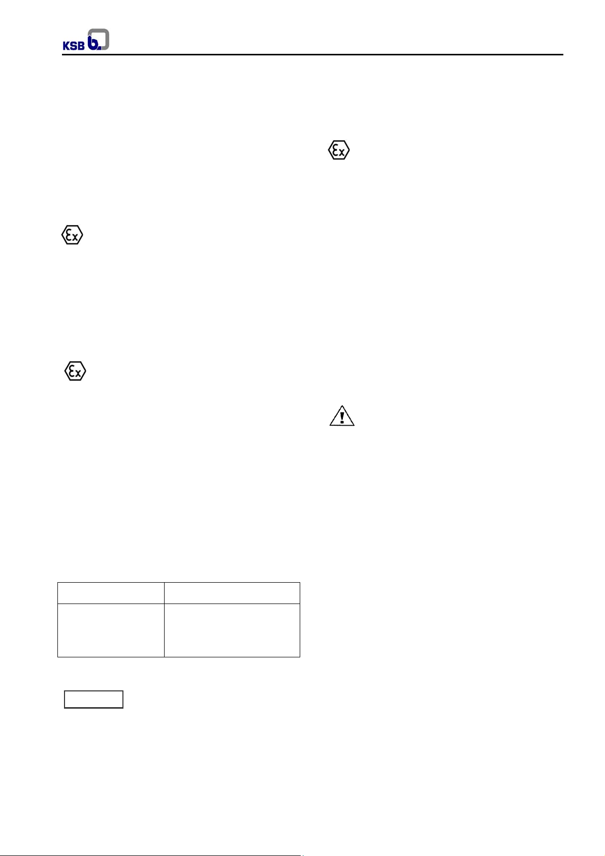
4.3.3 Shaft seal
Shaft sealing is effected by gland packing or single or
double acting mechanical seals.
The relevant seal version is shown in the mecha nical seal
drawing.
7
Page 8
Arragement drawing (examples)
Gland packing (special variant-consult KSB to use in
explosive atmospheres)
WKT
212 Intermediate shaft
383 Bearing spider
400.2 Flat gasket
529.3 Bearing sleeve
545.3 Bearing bush
711.1 Riser pipe
Fig. 02
Mechanical seal
Mechanical seal
Single-acting
Fig. 03
Mechanical seal
Double-acting
Fig. 04
4.3.4 Bearing arrangement
4.3.4.1 Pump bearings
The pump shaft runs in two plain bearings.
The bearing at the suction end is arranged in the suction
casing (106) and the bearing at the discharge end is
arranged in the discharge casing (107). Both these
bearings are lubricated by the product pumped.
4.3.4.2 Intermediate shaft bearings
(See fig. 05)
The intermediate shafts are guided by bearing spiders
(383) with built-in bearing bushes (545.3) between the
lengths of column pipe. Their construction and lubrication
corresponds to that of the pump bearings.
Fig. 05 Intermediate shaft bearing
4.3.4.2.1 Rigid Couplings for intermediate shafts
Depending on the shaft diameter, rotational speed,
switching frequency and type of driver, either rigid
screwed couplings, or split (muff) couplings are used to
connect the intermediate shafts to one another and to
transmit the driving torque.
In order to prevent the unscrewing (slackening) of
screwed couplings during reverse rotation pumping sets
fitted with such couplings must be provided with a revers e
rotation stop device.
Hollow shaft motors and hollow shaft bevel gears are
equipped with such a reverse rotation stop device.
Electric motors of V1 type series are however not so
equipped, and the direction of rotation of such motors
should therefore be checked before connection to the
shafting. It is therefore preferable to use split (muff)
couplings in conjunction with V1 type series electric
motors. The type of coupling applying to your installatio n
can be ascertained from the data sheet attached to the
Order confirmation.
See figures below for construction and arrangement.
Screwed coupling Split (muff) coupling
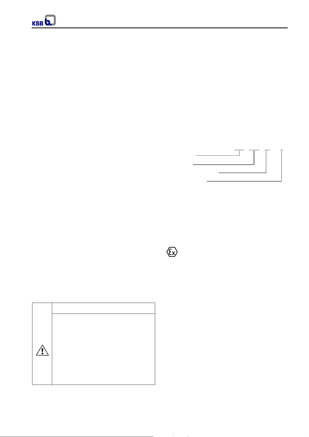
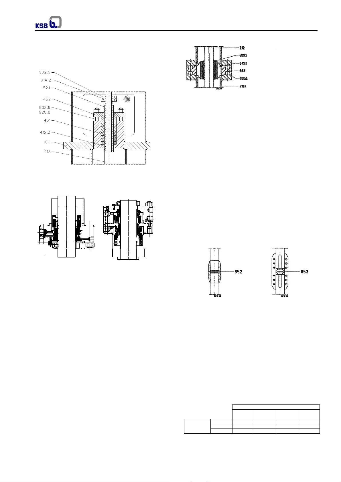
4.3.4.3 Thrust bearing
(See fig. 07 and 08 for construction).
The thrust bearing arranged in the motor lantern absorbs
the weight of the complete pump rotor, including the
weight of the intermediate shafts (212) and drive shaft
(213), and the radial forces which arise, it also absorbs
the residual axial thrust generated, and transmits all these
weights and forces to the motor lantern. Depending on
the values 3 different configurations are available. See
fig. 06. The bearing is oil lubricated, in the normal
execution.
Oil mist lubrication is possible, however it is special and
made up on consult.
Pump sizes
Thrust
bearing
constructions
VÖR 6311 6312 6315 6317
VÖQJ 311 312 315 317
VÖB 25 (7311) 35 (7312) 45 (7315) 60 (7318)
40 50 and 65
80 and
100
125 and
150
Fig. 06
8
Page 9
WKT
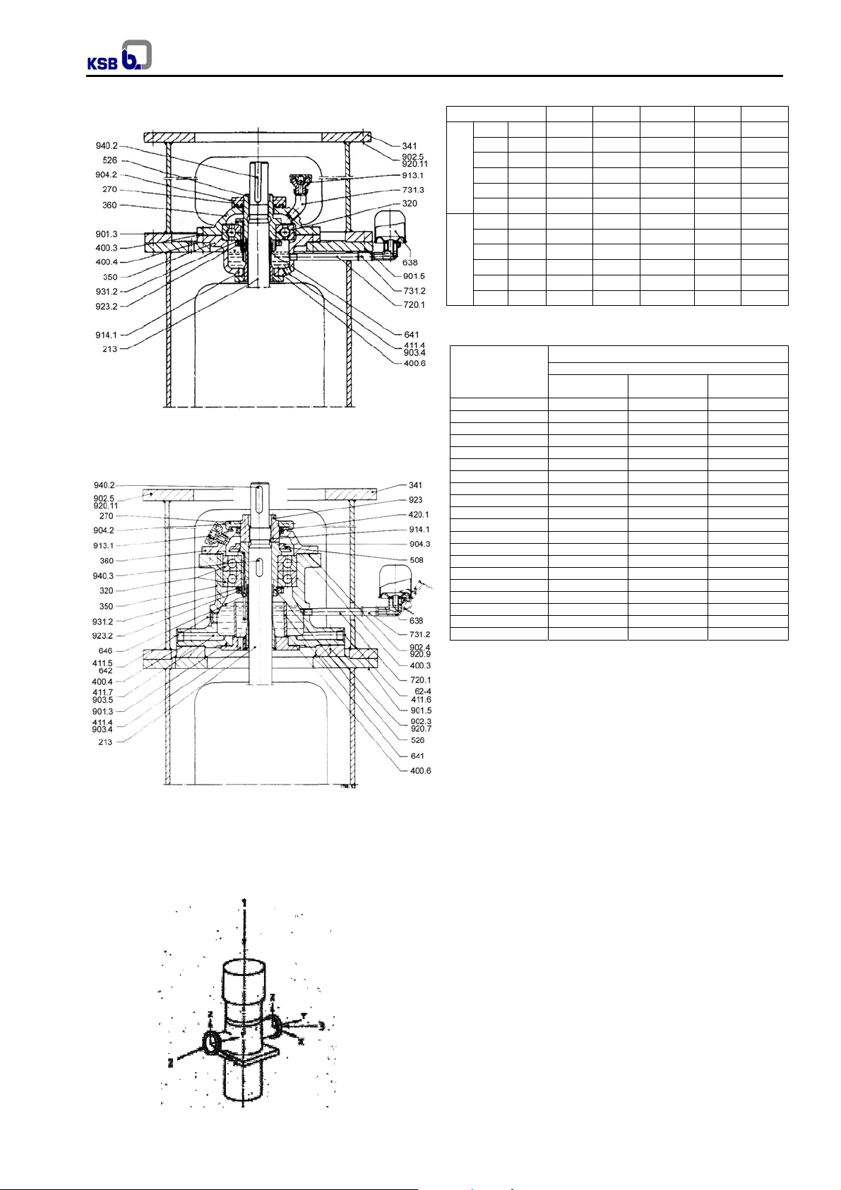
p
VÖB and VOQJ
Pump size 40 50/65 80/100 125 150
Fx N 1500 1800 2500 3000 3500
Fy N 1500 1800 2500 3000 3500
Fz N 1500 1800 2500 3000 3500
Mx N.m 1200 1500 2000 2500 3000
Suction
My N.m 1200 1500 2000 2500 3000
Mz N.m 1200 1500 2000 2500 3000
Fx N 800 1500 2000 2500 3000
Fy N 800 1500 2000 2500 3000
Fz N 800 1500 2000 2500 3000
Mx N.m 500 1200 1500 2000 2500
My N.m 500 1200 1500 2000 2500
Discharge
Mz N.m 500 1200 1500 2000 2500
4.3.6 Noise characteristics
Fig. 07 Construction of support bearing VÖB (deep
groove ball bearing and VÖQJ (four point contact
bearing).
VÖB
Fig. 08 Construction of support bearing VÖB
4.3.5 Permissible forces and moments at the
nozzles
For max. permissible forces & moments refer table below.
Fig. 09
Rated power input
P
110,0 79,0 77,0 76,0
132,0 79,5 77,5 76,5
160,0 80,0 78,0 77,0
200,0 81,0 79,0 77,5
250,0 81,5 79,5 78,5
400,0 83,0 81,0 80,0
500,0 84,0 82,0 80,5
750,0 85,0 83,0 81,5
1000,0 86,0 84,0 82,5
Sound pressure level
(kW)
N
2,2 60,0 60,0 -
5,5 65,5 65,0 64,5
11,0 70,0 68,5 67,5
15,0 71,5 70,0 69,0
22,0 73,5 72,0 71,0
30,0 74,5 73,0 72,0
37,0 75,5 74,0 73,0
45,0 76,0 74,5 73,0
55,0 76,5 75,0 73,5
75,0 77,5 76,0 74,5
90,0 78,0 76,5 75,0
2900
1/min
Pump only
1450
1/min
L
(db)
A
980
1/min
Measured at a distance of 1m from the pump outline (as per DIN 45635
Part 1 and 24). Room and foundation influences have not been included.
The tolerance for these factors is 1 to 2 dB.
Increase for 60 Hz operation
Pump without motor: -- Pump with motor:
3500min-1:+3dB, 1750min-1: + 1dB, 1160min-1: ---dB
4.4 Accessories
As a general rule, the following items are supplied with
the pump:
- Motor lantern,
- Special tools and tackles for assembly / disassembly
of conical coupling,
On request the following items can be supplied amongst
others:
- Coupling: flexible coupling with spacer,
- Coupling guard,
- Coupling extractor device,
- Motor,
- Base plate: welded construction,
- Pressure gauges for suction and discharge,
- ARC valve,
- Suction strainer.
4.5 Dimensions and weights
For dimensions and weights please refer to the general
arrangement drawing of the pump.
9
Page 10

5. Installation at site
Pumps should be installed, leveled and aligned by
qualified people. When this service is inappropriate
executed, it can have as consequence, operation
troubles, premature wear and irreparable damage.
Foundation Plan drawing (FU) informs pump dimension,
weights, foundation arrangement, connection sizes and
position of fixation elements.
Assure that all parameters for handling and operation
(access, assembly area, connections for assembly
equipment, cranes, etc) were perfectly established before
pump installation activities.
5.1 Safety regulations
Equipment operated in hazardous locations
must comply with the relevant explosion
protection regulations. This is indicated on the pump
name plate and motor name plate (see 2.9).
5.2 Checks to be carried out prior to installation
All structural work required must ha ve been prepared
in accordance with the dimensions stated in the
dimension table / general arrangement plan.
In case of concrete foundations they shall have
sufficient strength (min.class X0) to ensure safe and
functional installation in accordance with DIN 1045- 2
or equivalent standards.
Make sure that the concrete foundation has set firmly
before placing the unit on it. Its surface shall be truly
horizontal and even. The foundation bolts shall be
inserted in the soleplate.
5.2.1 Place of installation
The distributor casing, the pipe assembly and
certain areas of the soleplate take on roughly the
same temperatures as the medium handled. The motor
stool or bearing bracket lantern must not be insulated.
Take the necessary precautions to avoid burns.
5.3 Foundation
A special base frame must be fitted flush on shims in the
foundation or cover aperture to receive the pump set. T he
concrete base must have set before the base frame is
fitted.
Carefully level the machined seating face for the barrel
flange using a precision spirit level; use stainless steel
shims to compensate for any differences in height.
Do not grout and concrete in the base frame until the
pump set has been installed and the levels rechecked.
5.4 Barrel cleaning
Before mounting of barrel in the pit clean carefully inner
side of the barrel, keeping it horizontally and tilti ng it as
and when required till it is absolutely cleaned up.
5.5 Mounting
Fit the barrel separately in the leveled base frame,
carefully align and secure on the base frame.
WKT
Fit and align pump set and driver as described in section
5.6.
Then concrete in the base frame; re-check the alignment
and secure the barrel flange to the base frame using
studs and nuts.
5.6 Aligning the pump / drive
The pump unit consisting of pump, coupling and drive has
been mounted on a common set and is carefully aligned
in the manufacturing works.
The following instructions also apply to units not mounted
on a common set.
After connecting the piping and priming
Caution
the system, it is essential to re-check
the alignment at operating temperature.
operating behavior and may result in damage to the
bearings and shaft seals as well as premature coupling
wear.
Please note:
The pump set is correctly aligned, if a straight-edge
placed axially on both coupling halves is the same
distance from each shaft at all points around the
circumference. In addition, the distance between the two
coupling halves must remain the same all around the
circumference. Use a feeler gauge, a wedge gauge or a
dial micrometer to verify (see figs. 10 and 11).
Fig. 10 - Aligning the coupling with the help of a gauge
and a straight-edge
Fig. 11 - Aligning a spacer-type coupling
The radial and axial deviation between the t wo coupling
halves must not exceed 0, 1 mm.
The alignment of the pump and drive shall preferably be
checked by means of a dial micrometer. For this purpose
Incorrect alignment and inadmissible
Caution
coupling displacement will affect the
10
Page 11

remove the coupling spacer after having marked its
installation position by dotting marks (balancing
condition).
At the same time check the motor´s direction of rotation,
with the pump decoupled (see 6.1.7). The direction of
rotation must correspond to the direction indicated by the
arrow on the pump. Verify by switching the motor on and
then off again immediately. Fig. 12 ilustrates examples of
possible dial micrometer arrangements.
Fig. 12 - Aligning a spacer-type coupling with a dial
micrometer
Admissible run-out of coupling face (axial) max. 0,1 mm.
Admissible radial deviation, measured over the complete
circumference, max. 0,2 mm.
5.7 Connecting the piping
Never use the pump itself as an
Caution
anchorage point for the piping. The
permissible pipeline forces must not be exceeded (see
section 4.3.5).
The pipelines shall be anchored in c lose proximity to the
pump and connected without transmitting any stresses or
strains. The nominal diameters of the pipelines shall be at
least equal to the nominal diameters of the pump nozzles.
It is recommended to install check and shut-off elements
in the system, depending on the type of plant and pump.
It must be ensured, however, that the pump can still be
drained and dismantled without problems.
Thermal expansions of the pipelines must be
compensated by appropriate measures so as not to
impose any extra loads on the pump exceeding the
permissible pipeline forces and moments.
An excessive, impermissible increase in the
pipeline forces may cause leaks on the pump
where the fluid handled can escape into the atmosphere.
Danger of life when toxic or hot fluids are handled!
The flange covers on the pump suction and discharge
nozzles must be removed prior to installation in the
piping.
After the piping has been connected, it
Caution
must be easy to rotate the pump shaft by
hand at the coupling.
Recommendations for suction
In the pump installation, please consider the following
conditions:
a) Check minimum distance from bottom well up to
suction outlet or strainer according to installation (see
foundation plan).
b) Check liquid minimum level above pump casing, in
order to avoid dry operation, cavitation or vortex.
WKT
c) In case of frequent liquid level variation, it should
foreseen the installation of protection system against
operation below the minimum level.
d) In case of liquid with solids in suspension or with
excessive dirty, it should foreseen strainer in the pump
inlet.
Recommendations for discharge piping
The discharge piping assembly should comply with the
following considerations:
a) It should have disposals for water hammer control,
every time the overpressure values, deriving from liquid
return in long pipings, exceeds the recommended values
for piping and pump.
b) In the points where it is necessary to extract the air it
should foreseen vent valves.
c) It is necessary to foreseen tie bolted assembly joints, to
absorb system reaction efforts, deriving from applicable
loads.
d) Safety valves, relief disposals and other operation
valves, besides those mentioned, should foreseen when
necessary.
5.7.1 Auxiliary connections
The dimensions and locations of the auxiliary
connections (cooling, barrier liquid, flushing liquid, etc.)
are indicated on the general arrangement drawing or
piping layout.
These connections are required for proper
Caution
functioning of the pump and are therefore
of vital importance!
5.7.2 Coupling guard
In compliance with the accident prevention
regulations the pump must not be operated
without a coupling guard.
If the customer specifically requests not to include a
contact guard in our delivery, then the operator must
supply one. In this case, it is important to make sure that
the materials selected for coupling and coupling guard
are non-sparking in the event of mechanical contact.
KSB’s scope of supply meets this requirement.
5.8 Final check
Re-check the alignment as described in section 5.6 and
verify the correct distance between the coupling and the
coupling guard.
It must be easy to rotate the shaft by hand at the
coupling.
5.9 Connection to power supply
Connection to the power supply must be effected
by a trained electrician only. Check available
mains voltage against the data on the motor rating plate
and select appropriate start-up method.
We strongly recommend to use a motor protection device
(motor protection switch).
In hazardous areas, compliance with IEC60079-
14 is an additional requirement for electrical
connection.
11
Page 12

6. Commissioning, start-up / shutdown
Caution
importance. Damage resulting from non-compliance shall
not be covered by the scope of warranty.
6.1 Preparations
6.1.1 Recommended safety instrumentation for pump
a) Level switch for low level in suction tank.
b) Differential pressure indicator with switch across the
suction strainer.
Both these instruments should give trip signal for motor.
6.1.2 Lubrication
Check the bearing lubrication and correctly fill with the
specified amount of lubricant. See 6.1.4 for lubricant fill
and quality.
6.1.3 Pre-commissioning checks
a) Flushing of suction tank, suction pipeline with water
b) Cleaning of suction strainer;
c) Barrel cleaning; see 5.4;
d) Shaft seal;
e) Fit suction and discharge pressure gauges;
f) Check functioning of all interlocks by stimulation
g) Priming – see 6.1.6 for details;
h) Check free rotation of shaft manually.
6.1.4 Lubrication
Oil lubrication
The support bearing is lubricated by the oil fill in the
bearing housing (350). An oil elevator tube (646) inside
the centering sleeve (526) supplies oil to the antifriction
bearing. The requisite oil level is maintained by a
constant level oiler (638). The reservoir of this constant
level oiler must therefore always be kept topped up with
oil.
Filling and topping up (see fig. 13).
Compliance with the following
requirements is of paramount
after chemical cleaning. Take care to blind the pump
suction and discharge nozzles before flushing;
I) Check shaft seal and pack as described in
6.1.5.1 (applicable for gland packing execution
only);
II) Remove auxiliary piping for mechanical seal ie.
cooling, flushing, quenching, etc. It must be
thoroughly cleaned with water, dried and then
refitted.
method;
WKT
Filling and topping
Remove the protective case of the constant level-oiler.
Unscrew vent plug. Pour in the oil through the vent plug
tapping hole after having removed out the reservoir of the
constant level oiler until oil appears in the vertical portion
of the connection elbow. Then fill the reservoir of the
constant level oiler with oil and snap it back into operating
position. Screw vent plug in again. After a short time
check whether the oil level in the reservoir has dropped. It
is important to keep the reservoir properly filled at all
times.
The oil level should always be belo w the level of the vent
opening arranged at the top edge of the connection
elbow.
Fig.13 - Filling with oil
65
80
100
3
125
150
2
/s
12
1. Oil level in bearing housing and in connection elbow.
2. Position for topping up of oil level make-up quantity.
3. Oil level in oil reservoir after filling of same.
Oil changes and oil requirements
The first oil change should take place after the first 300
hours of operation, and subsequent oil changes should
be effected after every 3000 hours of operation, but at
least once a year.
Unscrew and remove the drain plug (903.4) on the
bearing housing and drain the oil. After draining of the
bearing housing, replace the drain plug and fill in fresh oil.
Pump sizes 40 50
Oil fill 1) ltrs 0,3 0,5 0,6 1,2
1)
Oil filling quantity (including constant level oiler and filler
pipe).
Fig. 14 Oil requirements
Oil specification
The oil used should exhibit the following characteristics:
Kinematics viscosity at 50ºC = 30 to 45 mm
Density at 20ºC = 0,9 kg/dm
Flash point = at least 150ºC
Pour point = below -5ºC
Ash content = not exceeding 0,05%
Neutralization number = not exceeding 0,3
Asphaltenes = 0%
Page 13

Lubrication by product pumped
The pump bearings and intermediate shaft bearings ar e
lubricated directly by the product pumped (suction side
bearing by inlet pressure and intermediate shaft bearings
by liquid at pump discharge pressure). No special
maintenance of these bearings is necessary, but the
pump must not be allowed to run dry.
6.1.5 Shaft seal
6.1.5.1 Gland packing
Gland packings supplied with the pump
Caution
have to be installed prior to pump startup
(unless they were fitted prior delivery).
The gland packing must be tightened gently and evenly.
It must be easy to rotate the shaft by hand.
a) Fitting new packing
Thoroughly clean the packing compartment and the shaft
protection sleeve, and coat them with molybdenum
disulphide. Insert neck ring (457), if any, and press it
home until it abuts. Insert the packing rings individually
and push them home with the aid of the stuffing bo x gland
and the seal cage ring. The ring butt of each packing ring
should be offset 90º in relation to the joints of the
adjoining rigid. In case of lubrication by an external
source insert seal cage ring (458) so that it registers
opposite connection 10E.
Then insert the remaining packing rings individually.
Leave a sufficient clearance gap at the entrance of the
stuffing box for the positive guidance of the gland. The
inserted packing rings should only be lightly compressed
by the gland and the nuts.
Then the nuts should be slackened and tig htened again
by hand. The even seating of the gland should be
checked with a feeler gauge, with the pump subjected to
suction pressure.
b) Removing the packing
Slacken clamping ring (184) and remove it from shaft
protection sleeve (524), undo stuffing box gland (452) and
pull it out of stuffing box housing.
Pull the top packing rings out of stuffing box housing
(451) with the aid of a packing ring extractor, pull out seal
cage ring (458), if any, then remove the remaining
packing rings and examine shaft protection sleeve (524)
for signs of damage.
Clean the packing compartment and coat it with
molybdenum disulphide.
Pack the stuffing box as described under a) above.
N.B.
The stuffing box should drip slightly whilst the pump is
running the leakage rate should amount to between 2 and
3 l/h. If your pump has sealing and cooling liquid
connections in use, they should be checked for
unimpeded flow. When the stuffing box gland has been
repeatedly tightened in service until it a buts, it is time to
renew the packing in the stuffing box.
WKT
Packing material
When selecting the packing material, remember to
ascertain its compatibility with the product pumped.
Always use new packing material, preferably material
which has been stored for a certain period, to repack the
stuffing box.
Pump
sizes
40
50
65
80
100
125
150
dws = Outer diameter of shaft protection sleeve
da = Inner diameter of packing compartment
Fig. 15 Dimension of packing compartment and packing.
6.1.5.2 Mechanical seal
Caution
supply tank, the tank must be fitted in accordance with
the general arrangement drawing (see also 6.1.6).
Quench feed must also be provided during pump
shutdown. On variants with pressurized dual mechanical
seals, apply barrier pressure as specified in the g eneral
arrangement drawing prior to starting up the pump (see
6.1.6). Barrier pressure must also be provided during
pump shutdown.
For external liquid supply, the quantities
Caution
and pressure specified in the data sheet
and general arrangement drawing shall be applied.
6.1.6 Priming the pump and checks to be carried out
The barrel must be filled at all times with product.
The pump body must be vented through the discharge
pipe during priming before commissioning.
6.1.6.1 Vacuum balance line
If the pump has to pump liquid out of a vessel under
vacuum it is advisable to install a vacuum balance line.
The suction area (barrel and distributor casing) is vented
via a line which remains open all the time. This line
should have a nominal size of 25 mm minimum. It should
be arranged to lead back into the vacuum vessel in
vapour phase.
Packing
compartment
dws / da
mm
40 / 60
45 / 70
45 / 70
55 / 80
55 / 80
80 / 112
80 / 112
The mechanical seal has been fitted prior
to delivery. On variants with quench
Number of
packing
rings
6
6
6
6
6
5
5
Width of
packing
mm
10
12,5
12,5
12,5
12,5
16
16
Overall
length
mm
1400
1500
1500
1600
1600
1800
1800
13
Page 14

WKT
Back to suction
(in vapour state)
Never run the pump dry!
Caution
Open or switch on all auxiliary lines (cooling, lubricati on,
sealing liquid etc) and ensure they are not blocked.
For water cooling, use suitable non-aggressive cooling
water not liable to form deposits and not containing
suspended solids. (Hardness: on average 5dH; (~1
mmol/l); pH > 8, or conditioned and neutral with regard to
mechanical corrosion).
Inlet temperature t
Outlet temperature t
Caution
Dry running of the pump will result in
mechanical seal failure and must be
= 10 to 30ºC
E
max. 45ºC
A
avoided!
6.1.6.2 Cooling
In general, the shaft seal must be cooled
Caution
if the vaporization pressure of the fluid
handled is higher than the atmospheric pressure.
Depending on the fluid handled, the system pressure and
the mechanical seal material, the limit may change
(example: hot water).
Observe permissible temperature
Caution
classes.
6.1.7 Checking the direction of rotation
When the unit has been connected to the electric power
supply, verify the following (local and national regulations
have to be taken into account separately):
For trouble-free operation of the pump,
Caution
the correct direction of rotation of the
impeller is of paramount importance. If running in the
wrong direction of rotation, the pump cannot reach its
duty point; vibrations and overheating will be the
consequence. The unit or the shaft seal might be
damaged.
Correct direction of rotation:
The direction of rotation must correspond to the direction
indicated by the arrow on the pump.
Never put your hands or any other objects into the
pump.
The motor’s direction of rotation
Caution
must be checked with the
pump/motor coupling removed.
If the motor runs in the wrong direction of rotation,
interchange two of the three phases in the control c abinet
or motor terminal box.
The safety instructions set forth in section 2.9.3 must be
complied with.
Fig. 16 – Decoupled drive
6.2 Start-up
Before starting the pump ensure that the shut-off element
in the suction line (if any) is fully open.
The pump may be started up against a closed dischargeside swing check valve or slightly open shut-off valve.
Only after the pump has reached full rotational speed
shall the shut-off valve in the discharge line be opened
slowly and adjusted to comply with the duty po int. When
starting up against an open discharge-side shut-off valve,
take the resulting increase in input power into account!
Pump operation with the shut-off
Caution
valves in the discharge and
suction pipes closed is not permitted.
The permissible pressure and temperature limits might be
exceeded. In extreme cases, the pump may burst.
After the operating temperature has
Caution
been reached and / or in the event of
leakage, switch off the unit and re-tighten the applicab le
bolts. Permissible tightening torques see 7.5.3.
Caution
Check the coupling alignment at
operating temperature as described in
section 5.6 and re-align, if necessary.
Immediate steps after start up
After start up and with pump in process, please observe
the following items:
a) Control electric power consumption (amperage) and
voltage;
b) Certify that the pump runs free of vibration and
abnormal noises;
c) Control support bearing temperature, which can
reach up to 40ºC above ambient temperature;
however the sum of them cannot exceed 82ºC.
The above items should be controlled each 15 minutes
during the first 2 hours operation. If everything is normal,
new controls should be made each 1 hour, during the first
5 up to 8 hours. If there is anything abnormal during this
period, please consult chapter Functioning Abnormalities
and its eventual Causes.
6.2.1 Minimum flow
(For the protection of the pump when operating at low
loads).
14
Page 15

General
The power absorbed by the pump does not decrease
proportionately with decreasing rate of flow, but on the
contrary still amounts to more than 50% of the power
absorbed at the design duty point at zero flow (pump shut
off point). In order to carry off this energy which is
converted into heat inside the pump, it is necessary to
maintain a minimum rate of low through the pump.
In the case of pumps with discharge nozzles of nominal
sizes between 40 and 150 this minimum rate of flow
normally amounts to 0,15 Qopt, taking the heat conditions
and the pattern of the characteristic curve into account.
In the case of pumps with larger sizes of discharge
nozzle, this minimum rate of flow amounts to 0,2 Qopt.
Qopt = Rate of flow at maximum efficiency of the pump.
The pump should only be operated at
Caution
rates of flow below the minimum rate of
flow during the switching on and switching off process.
Excessive wear and damage to the pump cannot be
excluded under these circumstances.
Minimum flow circulation via a permanent bypass
The permanent bypass recirculation is selected for plants
with relatively low pressures and low minimum flow rates.
This system is very attractive from the point of view of low
first cost, but is uneconomic in operation because the
minimum flow (or bypass flow) has to be circulated over
the entire operating range of the pump. When sizing the
pump, the bypass rate of flow must be added to the pump
capacity.
In order to ensure the minimum flow, an orifice plate is
fitted in the bypass line between the pump and the
suction vessel.
Minimum flow circulation via an automatic
recirculation valve
The automatic recirculation valve ensures the minimum
flow protection requirement simply and reliably. It is
mounted vertically in the discharge line between the
pump discharge nozzle and the isolating valve, in such a
way that the fluid flow through it from bottom to top.
As soon as the rate of flow of the pump falls below a
given minimum value, the bypass outlet on the automatic
recirculation valve opens sufficiently wide for a
predetermined minimum flow quantity to pass through
and be maintained even when the rate of flow through the
main discharge line is reduced to zero.
6.3 Shutdown
Close the shut-off valve in the discharge line.
If the discharge line is equipped with a non-return or
check valve, the shut-off valve may remain open. If shutoff is not possible, the pump will run in reverse direction.
This may cause damage to mechanical
Caution
seals which are not bi-directional!
The reverse runaway speed must be lower than the rated
speed.
Switch off the drive, making sure that the unit runs down
smoothly to a standstill.
Close the auxiliary lines but do not turn off the cooling
liquid supply, if any, until the pump has cooled down.
WKT
Please refer to section 6.1.5.2.
In the event of frost and / or prolonged shutdowns, the
pump – and the cooling chambers, if any – must be
drained or otherwise protected against freezing.
6.4 Operating limits
The pump´s / unit´s application limits regarding
pressure, temperature and speed are stated on
the data sheet and must be strictly adhered to!
If a data sheet is not available, contact KSB!
6.4.1 Temperature of the fluid handled, ambient
temperature, bearing temperature
Caution
sheet or the name plate unless the written consent of
the manufacturer has been obtained. Damage resulting
from disregarding this warning will not be covered by the
KSB warranty.
Bearing bracket temperature see 7.2.1.
The safety instructions set forth in section 2.9 must
be complied with.
6.4.2 Switching frequency
To prevent high temperature increases in the motor and
excessive loads on the pump, coupling, motor, seals and
bearings, the switching frequency shall not exceed the
following number of start-ups per hour (S).
If the above switching frequencies are exceeded, please
contact the motor manufacturer or KSB.
6.4.3 Density or fluid pumped
The power input of the pump will increase in proportion to
the density of the fluid pumped. To avoid overlo ading of
the motor, pump and coupling, the density of the fluid
must comply with the data specified on the purchase
order.
6.4.4 Abrasive fluids
When the pump handles liquids containing abrasive
substances, increased wear of the hydraulic s ystem and
the shaft seal are to be expected. The intervals
recommended for servicing and maintenance shall be
shortened.
6.4.5 Minimum / Maximum flow
Recommended operation flow range is Q = 0,5 up to
1,15 Q
Q
For minimum flow in short periods of operation see 6.2.1.
The data refer to water and water-like liquids. However, if
the physical properties of the fluids handled are different
from water, the calculation formula below must be used to
check if an additional heat build-up may lead to a
Do not operate the pump at temperatures
exceeding those specified on the data
Motor rating (kW) max. S (start –ups / h)
up to 12 15
up to 100 10
more than 100 5
opt.
= optimum efficiency
opt
15
Page 16

dangerous temperature increase at the pump surface. If
necessary, the minimum flow must be increased.
To = Tf +
= g * H / c * * (1 - )
c Specific heat [ J / kg K ]
g Acceleration due to gravity [ m / s
2
]
H Pump head [ m ]
Tf Temperature of fluid handled [ ºC ]
Temperature of casing surface [ ºC ]
T
o
Pump efficiency at duty point [ - ]
Temperature difference [ ºC ]
6.5 Shutdown / storage / preservation
Each KSB pump leaves the factory carefully assembl ed.
If commissioning is to take place some time after delivery,
we recommend that the following measures be taken for
pump storage.
6.5.1 Storage of new pumps
- New pumps are supplied by our factory duly
prepared for storage. Maximum protection for up to 6
months, if the pump is properly stored indoors.
- Store the pump in a dry location.
- Rotate the shaft by hand once a month.
6.5.2 Measures to be taken for prolonged shutdown
1. The pump remains installed; periodic check of
operation
In order to make sure that the pump is always ready
for instant start-up and to prevent the formation of
deposits within the pump and the pump intake area,
start up the pump set regularly once a month or once
every 3 months for a short time (approx. 5 minutes)
during prolonged shutdown periods.
Prior to an operation check run ensure that there is
sufficient liquid available for operating the pump.
2. The pump is removed from the pipe and stored
Before putting the pump into storage, carry out all
checks specified in sections 7.1 to 7.4. Then apply
appropriate preservatives:
- Spray-coat the inside wall of the pump casing,
and in particular the impeller clearance areas,
with a preservative. Spray the preservative
through the suction and discharge nozzles. It is
advisable to close the pump nozzles (e.g. with
plastic caps or similar).
6.6 Returning to service after storage
Before returning the pump to service, carry out all checks
and maintenance work specified in sections 7.1 and 7.2.
In addition, the instructions laid down in the
sections on “ Preparations “ (6.1) and
“Operating Limits “(6.4) must be observed.
Immediately following completion of the work, all
safety-relevant and protective devices must be
re-installed and / or re-activated.
WKT
7. Servicing / maintenance
7.1 General Instructions
The operator is responsible for ensuring that all
maintenance, inspection and installation work be
performed by authorized, qualified specialist personnel
who are thoroughly familiar with the manual.
A regular maintenance schedule will help avoid expensive
repairs and contribute to trouble-free, reliable operation of
the pump with a minimum of maintenance expenditure
and work.
Work on the unit must only be carried out
with the electrical connections disconnected.
Make sure that the pump set cannot be switched on
accidentally (danger to life!).
draining the fluid see to it that there is no risk to
persons or environment or the environment. All
relevant laws must be adhered to (danger to life)!
7.2 Servicing / inspection
7.2.1 Supervision of operation
The pump must never be allowed to run dry.
Always ensure a sufficient liquid level above the pump
inlet.
Prolonged operation against a closed shut-off
valve is not permitted. When operating the pump
set with the shut-off valve in the discharge line slightly
open for a short period of time, the permissible pressure
and temperature limits must not be exceeded.
A special design is required to comply with
temperature class T6 in the bearing area. In
such cases, and if ambient temperature exceeds 40ºC,
contact the manufacturer.
Verify correct oil level as described in section 6.1.4.
The shut-off elements and the auxiliary feed lines must
not be closed during operation.
Any stand-by pumps installed shall be started up
regularly, e.g. once a week, to keep them operational.
Attention shall be paid to the correct functioning of the
auxiliary connections. The cooling system must be
thoroughly cleaned at least once a year to ensure proper
cooling. Take the pump out of service for this purpose.
replaced in due time. Re-align the coupling as descr ibed
in section 5.6.
Supervision during operation
Depending on the labor availability and pump
responsibility, we recommend the following checks, and
in case of any abnormality the maintenance responsible
should be advised immediately.
Pumps handling liquids posing health
hazards must be decontaminated. When
Caution
Caution
The pump must run quietly and free
from vibrations at all times.
If the flexible coupling elements begin to
show signs of wear, they must be
16
Page 17

Weekly supervision
Check:
a) Pump operation point;
b) Motor current consumption and net tension value;
c) Vibration and abnormal noises;
d) Bearing housing temperature;
e) If applicable, the gland packing should drip slightly
whilst the pump is running. The gland should only be
tightened lightly.
Monthly supervision
Check:
a) Oil change interval, (if applicable).
Semestral supervision
Check:
a) Base frame and motor fix bolts;
b) Pump-motor set alignment;
c) Coupling lubrication (when applicable).
Annual supervision
Disassemble the pump for maintenance. After cleaning,
inspect bearings, (do it in detail), retainers and / or
bearing sealings, joints, O´rings, impellers, casing internal
regions (control also thickness), wear areas and coupling.
Note:
In installations with good operation conditions and
pumped liquid not aggressive to the pump materials, the
supervision can be done each 2 years.
7.2.2 Lubrication and lubricant change
See section 6.1.4.
7.3 Drainage / disposal
If the pump was used for handling liquids
Caution
posing health hazards, see to it that
there is no risk to persons or the environment when
draining the fluid. All relevant laws must be heeded. If
required, wear safety clothing and a protective mask!
If the fluids handled by the pumps leave residues which
might lead to corrosion when coming into contact with
atmospheric humidity, or which might ignite when coming
into contact with oxygen, then the unit must be flushed
through, neutralized, and then for drying purposes
anhydrous gas must be blown through the pump.
The flushing fluid used and any liquid residues in the
pump must be properly collected and disposed of without
posing any risk to persons or the environm ent. See also
section Discard (3.3.2).
7.4 Dismantling
Before dismantling the pump, secure it so as to
make sure it cannot be switched on accidentally.
The shut-off valve in the discharge line must be closed.
The pump set must have cooled down to
ambient temperature, pump pressure must
have been released and the pump must have been
drained including oil of bearing housing, if any.
WKT
Dismantling and reassembly must alw ays be carried
out in accordance with the relevant sectional
drawing.
7.4.1 Fundamental instructions and recommendations
Repair and maintenance work to the pump must on ly be
carried out by specially trained personnel; using original
spare parts (see 2.7).
Observe the safety regulations laid down in section
7.1. Any work on the motor shall be governed by the
specifications and regulations of the respective
motor supplier.
Dismantling and reassembly must alw ays be carried
out in accordance with the relevant general assembl y
drawing. The general assembly drawing and other
relevant documents are found in the annex. The
dismantling sequence can be derived from the
general assembly drawing.
In case of damage you can always contact our
service departments.
7.4.2 Dismantling the pump
7.4.2.1 Dismantling the thrust bearing
1. Pull the pump end half coupling off drive shaft (213)
with the aid of puller. Remove key (940.4).
2. Unscrew and remove oil labyrinth (270);
3. Unscrew bearing cover (360), and remove centering
sleeve (526) together with antifriction bearing (320)
and bearing cover (360) from the shaft by twisting the
centering sleeve. Pull the bearing cover (360) off the
centering sleeve (526).
4. Dismantle constant level oiler (638) together with its
connecting pipe.
5. Unscrew bearing housing (350) force it off and pull if off
over shaft (213) together with oil stand pipe (641).
6. Unlock and unscrew withdrawal nut (923.2), push
antifriction bearing (320) off the centering sleeve,
clean it with wash oil and examine it.
7.4.2.2 Dismantling the shaft seal
Gland packing
1. Unscrew screws (914.31) in clamping ring (184).
2. Pull the shaft protection sleeve together with the
clamping ring off the shaft.
3. Unscrew hex nuts (920.31) and remove stuffing box
gland (452).
4. Remove packing rings (461) and seal cage ring (458)
from the stuffing box housing, if any.
Mechanical seal
See specific instructions.
17
Page 18

7.4.2.3 Dismantling the pump body
After a prolonged period of operation, it
Caution
may happen that individual rotor
components (impeller and distance bushes) are difficult to
pull off the shaft, in such cases, do not use force or
hammer blows. First try using a suitable rust solvent or a
puller device. If these measures do not lead to the
desired result, the components concerned can be
warmed up slightly and then pulled off or forced off. The
shaft should remain as cold as possible during the
warming up process. If rotor components are dismantled
by warming up, the shaft should subsequently be
checked for radial run out.
1. Unscrew studs and nuts (902.1 and 920.5) between
distributor casing (10-1) and column pipe main, force
off pump body together with column pipe, and
dismantle distributor casing. Carefully underpin the
drive shaft (213).
2. Dismantle the column pipe.
3. Unscrew the intermediate shaft coupling or
disassemble the muff coupling and remove drive shaft
(213).
4. Unscrew nuts (920.1) of tie rods (905) at suction end,
remove them and pull out the tie rods.
5. Force off suction casing (106).
6. Undo nut (920.2) and remove it together with the lock
washer (931.1).
7. Pull suction impeller (231) off pump shaft (211), and
remove key.
Underpin the stage casing.
8. Force off and remove stage casing (108) including first
stage diffuser (171.1) and suction side bearing. D o not
damage the sealing faces.
9. Pull the stage sleeve (521.1) from the shaft and
remove the split ring (501.2).
10. Pull the impeller (230) off the pump shaft (211) and
remove key. Support the stage casing.
11. Press off and remove the stage casing (108) and
diffuser (171.2).
12. Press the stage sleeve (521) from the shaft.
13. Dismantle all the remaining s tages in the same way
as described in points 10 to 12 above.
In the case of multistage pumps, mark the impellers
and stage casings in their correct sequence, to
facilitate reassembly.
14. Pull discharge casing (107) off the shaft and store the
shaft with due care.
7.4.2.4 Dismantling of pumps installed very deep
down
1. Carry out preparations as described in section 7.4.1.
WKT
2. Dismantle thrust bearing as described in section
7.4.2.1
3. Dismantle shaft seal as described in section 7.4.2.2.
4. Pull the pumping set far enough out of the barrel by
means of the distributor casing (10-1) to enable a pipe
clip to be attached some 50 cm beneath the next
column pipe joint.
Firmly fasten the pipe clip and lower the pumping set
again until the pipe clip rests on top of the barrel.
Unscrew the pipe joint connecting the lengths of
column pipe main, and lift the distributor casing and
the upper length of column pipe main (711.1) over the
drive shaft. Unscrew the intermediate shaft coupling or
disassemble the muff coupling and remove drive shaft
(213). Force off the complete intermediate shaft
bearing and pull it off over the shaft.
Examine the bearing and shaft for signs of galling
(seizure). If necessary, raise the pumping set by a
further length of column pipe main, again fit a pipe clip
and lower the pumping set until the pipe clip rests on
the barrel. Then dismantle the length of column pipe
main and the bearing. Lift the pump body out of the
barrel, then set it down and underpin it in the
horizontal position for dismantling.
5. Dismantle the pump body in accordance with section
7.4.2.3, points 4 to 14.
7.4.3 Examination of individual components
7.4.3.1 Shafts (211, 212, 213)
Inspect the bearing sleeves (529) on the shafts for signs
of galling (seizure). Slight traces of damage can be
removed by grinding within the permissible clearance
limits. If the touching up works should result in the
permissible clearances being exceeded, then new
bearing sleeves (529) must be placed on.
Carry out an out-of-round check on a lathe between dead
centres. The max. permissible shaft whip must not
exceed 0,03 mm.
Caution
readings will be erroneous.
If certain rotor components are replaced by new ones, or
have been touched up, or if a new shaft has been fitted,
the pump rotor must be balanced dynamically, preferabl y
at the max, operating speed of the pump, but at l east at
1000 1/min. The max. permissible residual eccentricity is
5 microns.
7.4.3.2 Bearing arrangement
Antifriction bearings (320)
Even if they only exhibit slight discoloration marks or
specks of rust, or signs of damage to the running
surfaces, the bearings must be replaced by new ones.
Make sure the shaft is accurately
centered on the lathe, as otherwise the
18
Page 19

Observe the greatest cleanliness when mounting the
bearings. Use washing oil to clean the old bearings. After
washing, the bearings should be dried and immediately
sprayed with oil.
Plain bearings (pump and intermediate shafts)
Examine the bearing bushes for signs of galling (seizure).
If necessary, fit new bearing bushes (see table, fig. 20).
7.4.3.3 Shaft seal
Soft packed stuffing box
Use new packing material every time the pump is
overhauled. The shaft protection sleeve (524) may only
be touched up very lightly by grinding.
If it exhibits signs of damage, a new shaft protection
sleeve should be fitted.
(For pump with impeller rings and inter stage bushes, see
supplementary sheet).
7.4.3.4 Pump body
Suction casing (106), discharge casing (107), stage
casings (108), impellers (230, 231), casing wearing rings
(502), bearing bushes (545), stage sleeves (521).
Ensure all the sealing faces are in perfect condition.
Check the plane parallelism of the faces at 4 points on
the circumference with a micrometer. The deviation must
not exceed 0,02 mm. Damaged faces can be machined
on a lathe. The surface roughness must not exceed
0.8 µm (micron meter).
The stage casings (108) and diffusers (171) are fitted with
renewable casing wearing rings (502).
Check the impellers and wearing rings for galling and
check the rotor clearances per fig. 19.
The casing wearing rings must be machined when fitted
and the max. permissible clearances must be respected.
Any increase in clearance must be made uniform at all
wearing points inside the pump.
If the bearing clearances are the same as or greater t han
the max. permissible clearances per Fig. 20. Fit new
oversized wearing parts and re-establish the “as new”
clearances.
Fitting new casing wearing rings (502)
1. Undo the allen grub screw, press the casing wearing
rings in the stage casing and diffuser out of the fit
taking care not to damage the fit. (see fig. 17).
2. Uniformly press new wearing rings.
3. Smooth down all impellers (230, 231) in the region of
the suction and discharge throttle section to a common
diameter, basing this on the most heavily scored
section.
WKT
Single deep grooves can be left untouched. See figs.
18 & 18a.
Fig. 17 Renewing the casing wearing rings.
Fig. 18 Smoothing out the throttling sections on the
impellers, see fig. 18a.
Pump
sizes
40
50
65
80
100
125
150
Smallest impeller neck
1st stage impeller
without wearing ring
88,2
103,2
113,2
128,2/118,2
143,2/148,2
178,2/168,2
213,2/198,2
2)
2)
2)
/188,23)
2)
Stage impellers
without wearing ring
78,2
88,2
98,2
113,2/118,2
128,2/148,2
148,2/168,2
198,2
2)
Fig. 18a Smallest permissible impeller neck dia and max.
diffuser bore dia.
1)
not for 1st stage (for single wearing ring execution)
2)
hydraulic WKL
3)
special hydraulic
If these limiting values are exceeded replace with new
spares.
7.4.3.5 Metaflex coupling
Check the flexible transmission elements for wear and
replace if necessary.
2)
2)
2)
Max.
Diffuser
bore
46,5
49,5
49,5
53,5/51,5
53,5/61,5
66,5/67,5
81,5/79,5
1)
2)
2)
2)
2)
19
Page 20

t
7.4.3.6 Rotor and bearing clearances
Pump sizes
Operating
temperature ºC
40 to 150 0 to +200
Fig. 19 Impeller / Casing wearing ring clearance.
Pump sizes
Operating
temperature ºC
40 to 150 0 to +105
40 to 150 +106 to +200 -
Fig. 19a Stage sleeve / diffuser clearance.
Pump size
40
50
65
80
100
125
150
Fig. 20 Plain bearing clearance (in mm referred to Ø).
Bearing 1
Min. Max. Min. Max. Min. Max.
0,040 0,106
0,050 0,128 0,060 0,152
s
stage
diffuser
Clearances mm on
0,4 1,0 0,6 1,2
“as new” max. perm. “as new” max. perm.
Cast iron / Cast iron AISI 316 / AISI 316
Clearances mm on
0,4 1,0 0,6 1,2
“as new” Max. perm. “as new” Max. perm.
Cast iron / Cast iron
Carbon Steel
Bearing in discharge
casing
0,050 0,128
0,060 0,152
7.4.3.7 Dynamic balancing of pump rotor
For this purpose, the pump rotor should be assembled as
follow:
Assembly proceeds from the front end; slip stage sleeve
(521) onto pump shaft (211) until it abuts against the shaft
shoulder. Insert the key and slip final stage im peller (230)
onto the shaft until it abuts.
Mount the stage sleeve (521) (sleeve (520), on pump size
150), - keys and impellers (230) of the remaini ng stages
in sequence, as described above. Fit the split ring (501)
and key (940.2). Push on the stage sleeve (529.1) and
suction impeller (231).
N.B. The impellers must be mounted in their correct stage
sequence.
Slip on lock washer (931.1) and clamp the mounted
components together on pump shaft (211) with the aid of
shaft nut (920.2).
Place the bearing sleeve and fix it with the circlip 932.1.
Before dynamic balancing, the rotor should be checke d for
true running (out-of-round) at the impellers (230) and at
the bearings. The measured out-of-round value must not
exceed 0,03mm. The rotor should then be balanced
dynamically at max. pump operating speed if possible but
at least at 1000 1/min. The max. permissible residual
eccentricity must not exceed 5 µm (micron meter). Before
final assembly in the pump, the pump rotor must be
dismantled again in reverse sequence to the assembly
procedure described above.
for material combination
12% Cr / 12% Cr
for material combination
AISI 316 / A743CF8M
12% Cr / 12% Cr
Cast iron / Cast iron
12% Cr / 12% Cr or Carbon Steel
Intermediate shaft bearing
0,050 0,128
7.5 Reassembly
7.5.1 General instructions
The pump shall be reassembled in accorda nce with the
rules of sound engineering practice.
Clean all dismantled components and check them for
signs of wear. Verify the dimensions given in fig. 18, 19 e
and 20. Damaged or worn components are to be replaced
by original spare parts. Make sure that the seal faces
are clean and that the sealing elements are properly
fitted.
Always use new sealing elements (O-rings / gaskets)
whenever the pump is reassembled. Make sure that new
gaskets have the same thickness as the old ones.
Gaskets made of graphite or other asbestos-free
materials must always be fitted without using lubricants
such as copper grease or graphite paste.
Avoid the use of mounting aids as far as possible. Should
a mounting aid be required after all, use a commercially
available contact adhesive (e.g. “Pattex”). The adhesive
shall only be applied at selected points (3 to 4 spots) and
in thin layers.
Do not use cyanoacrylate adhesives (quick-setting
adhesives)! If in certain cases mounting aids or antiadhesives other than described herein are required,
please contact the sealing material manufacturer.
Caution
All graphite gaskets must only be
used once!
Never use O-rings that have been glued together from
material sold by the metre.
WKT
20
Page 21

Caution
silicone-base or PTFE-base lubricants instead. O-rings
made of ethylene propylene shall only be coated with
silicone grease or soft soap; never use mineral oils or
greases!
The locating surfaces of the individual components must
be coated with graphite or similar before reassembly. The
same applies to screwed connections.
See section 7.5.2.5.1 for reassembly of pumps installed
deep down.
7.5.2 Preparations
Before reassembly of ring section pumps, the stage
sleeve “E” of each stage casing (108) and of the
associated impeller (230, 231) with stage sleeve (521)
must be measured. Any discrepancy in lengths must be
compensated by machining the stage sleeve (521) only,
and the end result must be E1 = E2. (See fig. 21).
If machining of the stage sleeve is required, it should be
shortened at both end faces in one operation on the
machine tool. The permissible end face whobble
(deviation from plane parallelism) is 5 µm (micron meter).
Do not damage the contact faces on the casing
components, diffusers, impellers, spacer and stage
sleeves before and during assembly. All pump
components, particularly the end contact faces, should be
thoroughly cleaned. If new impellers are fitted, or if the ol d
ones are touched up, the rotor must be balanced
dynamically.
7.5.2.1 Assembly of pump body
1. Put the key (940.3) on the pump shaft (211) and slide
the bearing sleeve (529.2) from the end, until it abuts
against the shaft shoulder. Place the circlip (932.2).
Do no coat o-rings with graphite or
similar products. Use animal fats or
Fig. 21 Measuring the stage length.
WKT
2. Push discharge casing (107) with fitted bearing bush
(545.2) and diffuser (171.2) onto pump shaft (211)
from the drive end.
3. Slide stage sleeve (521) – (sleeve (520) in the case of
pump size 150) – onto pump shaft (211) from the front
end, until if abuts against the shaft shoulder.
4. Inert key and slip final stage impeller (230) onto pump
shaft (211).
5. Insert diffuser (171.2) of the following stage into stage
casing (108) and mount the stage casing together with
O-ring (412) against discharge casing (107).
6. Mount the remaining stages in the sequence: stage
casing with diffuser, stage sleeve, impeller (230) –
observe the markings. Insert the split ring (501) and
key (940.2), press on stage sleeves (521.1), diffuser
(171.1) with suction side bearing and suction impeller
(231).
7. Put the lock washer (931.1) on the shaft and tighten up
the shaft nut (920.2).
8. Put the key (940.1), slide the bearing sleeve (529.1)
and fix it with the circlip (932.1).
9. Fit the suction casing (106) with bearing bush (545.1)
on the stage casing (108).
10. Clamp the discharge, stage and suction casings
together with the aid of the tie rods (905). Use a torque
wrench for this purpose.
11. Connect the drive shaft (213) or the intermediate
shaft (212) to the pump shaft (211) by means of screw
or muff coupling. Underpin the drive shaft /
intermediate shaft properly.
12. If applicable, lift the column pipe with gasket (400.1)
over the drive shaft / intermediate shaft and mount it
on the pump body.
13. Fasten the pump body with column pipe and gasket
(400.1) on the distributor casing.
7.5.2.2 Assembly of shaft seal
(See installation drawing for type of shaft seal fitted to
your pump.)
7.5.2.2.1 VSM Soft-packed stuffing box (fig. 02)
1. Slip the stuffing box gland (452) over the drive shaft
(213).
2. Slip the shaft protection sleeve (524) including the
O´ring and the clamping ring (184) over shaft (213).
3. Pack the stuffing box in accordance with section
6.1.5.1.
4. Adjust the shaft protective sleeve (524) with clamping
ring (184).
21
Page 22

7.5.2.3 Assembly of thrust bearing
Fig. 07 and 08
1. Thoroughly clean centering sleeve (526) and examin e
the oil retaining tube for unimpeded flow.
2a. Slip the four point contact bearing (320) with one
inner race onto the centering sleeve and then slip on
the second inner race.
2b. Slip de bearing(s) (320) onto the centering sleeve, in
case of deep groove ball or pair of contact angular
bearings.
Note: Prior to this, warm up the antifriction bearing to
80ºC approx. in an oil bath.
3. Slip on locking washer (931.2), screw on withdrawal
(923.2) nut , tighten it and lock it with the locking
washer.
4. Fit bearing housing (350) including oil stand pipe (641)
and gasket (400.6/4) on the distributor casing (10-1)
and fasten it.
5. Twist centering sleeve (526) together with previously
mounted antifriction bearing onto drive shaft (213).
6. Insert gasket (400.3), mount bearing cover (360) and
fasten it. The vee notches integrally cast into the
bearing housing and bearing cover must register
opposite one another on reassembly, and so must th e
cut-out on the gasket, to enable the oil return flow
grooves to fulfill their function properly.
7. Adjust the axial rotor position in accordance with
section 7.5.2.4.
8. Mount deflector (270).
9. Fit constant level oiler (638) together with its
connecting pipe.
7.5.2.4 Adjustment of axial position of pump rotor
The pump rotor position must be adjusted axially after
completion of mounting of the bearings and motor lantern
and before the drive coupling is mounted.
The total axial play of the rotor is ascertained by lowering
and raising it to its bottom and top abutments by means
of the centering sleeve (526) which has a 1,5 mm screw
thread pitch. The rotor is subsequently raised to its top
abutment, then lowered by an amount equal to 0,4 times
the total axial play. Thereafter the centering sleeve (526)
is locked in position by means of the gib key.
If the gib key cannot be slotted in because the slot i n the
centering sleeve does not register immediately opposite,
twist the sleeve to right or left until the nearest slot
registers with the gib key.
7.5.2.5 Final assembly and installation of pump
1. Mount pump end half coupling on drive shaft (213).
WKT
2. Lay internal auxiliary piping in accordance with the
installation drawing.
3. Examine barrel for dirt and clean it if necessary.
4. Carefully clean the sealing faces on the barrel and
distributor casing and insert the o’ring or gasket.
Check the parallelism of the sealing faces between
barrel flange and distributor casing flange.
5. Attach ropes to the motor lantern, carefully raise the
pump to a vertical position and fit in the barrel. Check
the alignment and bolt the distributor casing (10-1) on
to the barrel (10-3).
6. Connect the suction line and discharge line, refer to
section 5.7.
7. Mount driver and check coupling alignment. (see
section 5.6).
8. Fill in oil (see section 6.1.4).
9. Start up the pump in accordance with section 6.2.
7.5.2.5.1 Final assembly of pumps installed very deep
down
If the pumping set cannot be inserted in the barrel as a
complete unit because of its length, the pump body,
column pipe main, distributor casing, shaft seal and
bearings should be assembled as follows.
1. Inspect barrel for dirt and clean it if necessary.
N.B. Do not damage the special coatin g inside barrel and
column pipe main.
2. Assemble pump body in accordance with section
7.5.2.3, points 1 to 8.
3. Connect the pump shaft to the intermediate shaft by
means of a screwed or muff coupling (see section
4.3.4.2.1). Slip gasket (400.1) and column pipe (711.2)
over the shaft and attach them to discharge casing
(107). Mount a pipe clip on column pipe 711.2 and
fasten it securely.
4. Carefully raise the pump body to a vertical position and
lower it into the barrel (10-3) until the pipe clip rests on
the top rim of the barrel. Take care not to damage the
sealing face of the barrel flange. Then place the
intermediate shaft bearing with gaskets in position.
5. Mount the drive shaft (213) or the next length of
intermediate shaft (212). Slip the column pipe (711.1)
over the shaft and fasten it. Fasten a second pipe clip
on the upper length of column pipe (711.1). Lift the
pump, undo and remove the lower pipe clip, and lower
the pump into the barrel until the upper pipe clip rests
on the barrel flange.
6. Lay the gasket (between barrel and distributor casing)
on the pipe clip.
22
Page 23

7. Place the distributor casing (10-1) over the drive shaft
and fit it on the top flange of the column pipe m ain or
on the intermediate shaft bearing and fasten it.
8. Attach hoisting ropes to the distributor casing, raise the
pump, detach and remove the pipe clip, carefully c lean
the sealing faces on the barrel and distributor casing,
insert gasket (412.1 or 400.3) and lower the pump until
the distributor casing seats in its correct position on
the barrel flange.
On the construction with gasket, check the parallelism
of the sealing faces between barrel flange and
distributor casing flange.
9. Check the alignment and fasten the distributor casing
on the barrel.
10. Mount the shaft seal and the thrust bearing in
accordance with sections 7.5.2.2 and 7.5.2.3.
11. Adjust the axial position of the pump rotor in
accordance with section 7.5.2.4.
12. Mount the pump end coupling half on drive shaft
(213).
13. Connect the suction li ne and discharge line, refer to
section 5.7.
14. Mount the driver and check the coupling alignment
(see section 5.6)
15. Fill in oil (see section 6.1.4).
16. Start up the pump in accordance with section 6.2.
WKT
23
Page 24

7.5.3 Tightening torques of main fixation in N.m
WKT
Denomination Tie bolt / nut
Part Nº 905 / 920.1 920.2
Material
Pump size
WKT40 226 370 100 100 1,0 193 28,0
WKT50 226 465 100 100 1,0 193 28,0
WKT65 226 465 100 100 1,0 193 28,0
WKT80 460 650 100 100 1,0 193 28,0
WKT100 460 650 100 100 1,0 193 28,0
WKT125 2000 900 193 193 8,3 193 69,0
WKT150 2500 1000 193 193 8,3 193 135
Steel A193
Gr. B7/8,8
Nut
(First stage)
AISI 316
Hex. head
bolt / nut
(Column fixation)
901.1 and 901.2
/ 920.5
Carbon Steel
5.6/6
Stud / nut
(Column fixation)
902.1 / 920.5 902.9 / 920.9 902.5 / 920.3 902.2 / 920.6
Carbon Steel
5.6/6
Stud / nut
(Muff coupling)
AISI 316 / 304
(AISI 420)
Stud / nut
(Disch. head
Fixation or barrel)
Carbon Steel
5.6/6
Stud / nut
(Seal gland
fixation)
AISI 316 / 304
For other materials consult KSB.
7.6 Spare parts stock
When ordering spare parts, please indicate pump type and size, Producti on Order number, part number and designation.
This information can be obtained from the Data Sheet, Sectional Drawings and Parts List.
7.6.1 Recommended Spare parts for a 2 years operation to DIN 24296.
Part N
211/212/213 Shafts 1 1 2 2 2 3 30%
230 Impeller S-1 S-1
231 Suction impeller 1 1 2 2 2 3 30%
320 Bearing 1 1 2 2 3 4 50%
330 Bearing bracket - - - - - 1 2 parts
383 Spider bearing 1 1 2 2 2 3 30%
411 Gasket, complete (set) 150%
º
Denomination
Number of pumps (including stand-by pumps)
2 3 4 5 6 8 10 or more
Spare Parts Quantity
2x
2x
(S-1)
(S-1)
2x
(S-1)
3x
(S-1)
30%
412 O´ring complete (set) 1 1 2 2 3 4 50%
433 Mechanical seal 1 1 1 2 2 2 20%
461 Gland packing (set) 4 4 6 6 6 8 100%
502 Casing wear ring 2 2 2 3 3 4 50%
503 Impeller wear ring 2 2 2 3 3 4 50%
524 Shaft protective sleeve 1 1 1 2 2 2 20%
529 Bearing sleeves, complete 1 1 2 2 3 4 50%
545 Bearing bushes, complete 1 1 2 2 3 4 50%
840 Coupling 1 1 2 2 2 3 30%
--- Gaskets and O’rings sets 4 6 8 8 9 12 150%
If fitted
S = number of stages
24
Page 25

E
i
i
f
pump
8. Troubleshooting
se o
ve r
WKT
Cause Remedy
1)
Pump delivers
insufficient flow rate
Motor is overloaded
Excessive pump
discharge pressure
Increase in bearing
temperature
Leakage at the pump
Excessive leakage at
the shaft seal
1)
Pump pressure must be released before attempting to remedy faults on parts which are subjected to pressure.
2)
Request particulars.
xcess
Vibration during pump
operation
temperature inside the
The pump generates an excessively high
differential pressure.
Excessively high back pressure.
The pump or piping are incompletely vented
or primed.
Suction line or impeller (s) clogged.
Formation of air pockets in the piping.
The pump is warped.
NPSH available is too low (on positive
suction head installations).
Increased axial thrust. 2)
Air intake at the shaft seal. Fit new shaft seal.
Reverse rotation
Motor is running on two phases only.
Rotational speed is too low. 2)
Defective bearings. Fit new bearings.
Insufficient rate of flow. Increase the minimum rate of flow.
Excessive wear of the pump internals. Replace worn components by new ones.
Pump back pressure is lower than specified
in the purchase order.
Specific gravity or viscosity of the fluid
pumped is higher than that specified in the
purchase order.
Use of unsuitable materials. Change the Material combination.
Excessive rotational speed.
The connection bolts are slack. Tighten the bolts. /Fit new gaskets
Worn shaft seal.
Grooving, score marks or roughness or shaft
sleeve surface.
Lack of cooling liquid or fouled and clogged
cooling liquid compartment.
Vibrations during pump operation.
Pump set is misaligned.
Too much, too little, or unsuitable lubricant
quality.
The specified coupling gap has not been
maintained.
Operating voltage is too low. Increase the voltage.
Rotor is out of balance .
Open discharge valve further until the duty
point conditions have been attained.
Fit larger impeller (s)
Increase speed (applies to turbine driven or
I.C Engine driven pumps)
Vent or prime the pump and piping
completely.
Remove deposits in the pump and/or piping.
Alter piping layout.
If necessary fit a vent valve.
Check piping connections and pump fixing
bolts.
Check liquid level in suction vessel.
Open isolating valve in suction line fully.
Alter suction line if necessary, if the friction
losses in the suction line are excessive.
Check suction line strainer.
Make sure that the permissible rate of
pressure decrease is not exceeded.
Clean out balance holes in impeller.
Fit new casing wear rings.
Interchange two of the phases of the power
supply cable.
Replace the defective fuse.
Check electric connections.
Increase speed.
Increase voltage.
Adjust duty point accurately by means of the
isolating valve in the discharge line.
In case of persistent overloading, trim the
impeller (s) if necessary
2)
Reduce speed (applies to turbine driven or
I.C. engine driven pump).
Check condition of shaft se al and renew it if
necessary.
Check flushing liquid or sealing liquid
pressure
Fit new shaft sleeve.
Increase the flow of cooling liquid.
Clean out the cooling compartment.
Clean the cooling liquid.
Improve suction conditions. /Re-align the
pump. /Re-balance the impeller. /Increase
the pressure at the pump suction nozzle.
Check alignment at coupling and realign the
set if necessary.
Reduce quantity of or top up lubricant or
change lubricant quality.
Restore correct coupling gap in accordance
with the data on the installation plan.
Clean the rotor.
Rebalance the rotor dynamically.
2)
2) 3)
25
Page 26

9. Sectional drawing (part 1/2) - reference
WKT
902.2
920.6
26
Page 27

WKT
3
Sectional drawing (part 2/2) - reference
932.2
711.1
545.2
529.2
940.8
502.1
171.2
230
521.1
231
171.1
502.2
931.1
920.2
106
529.1
545.1
Main parts list
Description Part nº Description Part nº Description Part nº
Distributor casing 10-1 *) Casing wear ring 502.2 Stud 902.3
Suction can 10-3 Impeller wear ring 503.1 Stud 902.4
Suction casing 106 Impeller wear ring 503.2 Stud 902.5
Discharge casing 107 Oil thrower 508 Stud 902.7
Stage casing 108 Stage sleeve 521.1 Stud 902.9
Diffuser 171.1 Stage sleeve 521.2 Threaded plug 903.1
Diffuser 171.2 Stage sleeve 521.3 Threaded plug 903.2
Pump shaft 211 Centering sleeve 526 Threaded plug 903.4
Intermediate shaft 212 *) Bearing sleeve 529.1 Threaded plug 903.5
Drive shaft 213 *) Bearing sleeve 529.2 Threaded pin 904.1
Impeller 230 Bearing bush 545.1 Threaded pin 904.2
Suction impeller 231 Bearing bush 545.2 Threaded pin 904.11
Deflector 270 Disc 550.1 Tie bolt 905
Antifriction bearing 320 Disc 550.2 Socket head screw 914
Drive stool 341 Constant level oiler 638 Hex. nut 920.1
Bearing housing 350 Oil level pipe 641 Nut with two flats 920.2
Bearing cover 360 Oil level indicator 642 Hex. nut 920.3
Bearing spider 383 Venting 672 Hex. nut 920.4
Flat gasket 400.1 Coupling guard 681 Hex. nut 920.6
Flat gasket 400.2 Pipe 710.1 Hex. nut 920.7
Flat gasket 400.3 Riser pipe 711.1 Hex. nut 920.9
Flat gasket 400.4 Riser pipe 711.2 Hex. nut 920.11
Joint ring 411.1 Pipe double nipple 720.1 Bearing nut 923.1
Joint ring 411.2 Pipe double nipple 720.7 Bearing nut 923.2
Joint ring 411.3 Flange motor 801 Lock washer 931.1
Joint ring 411.4 Coupling 840 Lock washer 931.2
Joint ring 411.5 Muff Coupling 853 Circlip 932.1
Joint ring 411.6 Screw 900 Circlip 932.2
O-ring 412.1 Screw 900.1 Key 940.1
O-ring 412.2 Screw 900.3 Key 940.2
O-ring 412.3 Hex. head bolt 901.1 Key 940.3
Mechanical seal 433 Hex. head bolt 901.2 Key 940.4
Multiple ring 501.1 Hex. head bolt 901.3 Key 940.5
Multiple ring 501.2 Stud 902.1 Key 940.6
*) Casing wear ring 502.1
*) Additionally recommended spare parts Recommended spare parts
85
501.1
900.1
940.6
900.3
902.9
920.9
211
901.1
920.5
400.1
903.1
411.1
940.3
107
521.2
521.3
904.1
108
503.1
412.1
501.2
940.2
503.2
920.1
905
550.1
940.1
903.2
411.2
932.1
27
Page 28

Supplementary sheet
Pump with impeller wearing rings and interstage
bushes (see fig.01)
Pump sizes 40 to 150, pressure rating 20/40.
Supplements for sections:
Examination of individual components
Pump Body
Suction casing (106), discharge casing (107), stage
casings (108), impellers (230,231), impeller wearing
rings (503), casing wearing rings (502), interstage
bushes (541), distance bushes (521), or sleeves (520)
with pump size 150.
Ensure all the sealing faces are in perfect condition.
Check the plane parallelism of the faces at 4 points on
the circumference with a micrometer. The deviation must
not exceed 0,02mm. Damaged faces can be machined
on a lathe.
The surface roughness must not exceed 0, 8 microns.
The impellers (230, 231), stage casings (108), and
diffusers (171), are fitted with renewable wearing parts –
impeller wearing rings (503), casing wearing rings (502),
and interstage bushes (541). Check the wearing parts f or
galling and check the rotor clearances per figs. 5 and 6.
The wearing parts must only be machined when fitted
and the maximum permissible clearances must be
respected. Any increase in clearance must be made
uniform at all wearing parts inside the pump.
WKT
4. Calculate the average actual diameter of all
smoothed down impeller wearing rings. Adding this
to the “as new” clearance per figs. 4 and 5 gives the
bore diameter for the casing wearing rings,
tolerance + 0,04mm.
Stage casing
Shim
Diffuser
Fig. 02 Renewing the casing wear rings and stage
bushes
5. Align the stage casing (108) and diffuser (171) with
fitted casing wearing ring to the outer fit and
machine the wearing ring without changing setting.
smooth here
Casting wearing ring
Inter stage
bush
Lever
Fig. 01 Full Chrome design with impeller wearing rings
and interstage bushes, pressure rating 20/40.
If the rotor clearances are the same as or greater tha n
the max. permissible clearances specified in figs. 5 and
6, fit new oversizes wearing parts and reestablish the “as
new” clearances.
Fitting new casing wearing rings (502):
1. Undo the allen grub screw, press the casing wearing
rings in the stage casing and diffuser out of the fit,
taking care not to damage the fit (see fig. 02).
2. Uniformly, press new oversized casing wearing
rings (normally 2 mm allowance) into the bore
(cooling the rings makes this easier).
3. Smooth do wn all impellers (230, 231) in the region
of the fitted impeller wearing rings (503) to a
common diameter, basing this on the most heavily
scored impeller wearing ring. Single deep grooves
can be left untouched (see fig. 03).
Fig. 03 Smoothing out the throttle sections on the
impeller wearing rings.
Clearances
Clearances for material
Pump sizes
40 to 150 0 to +200 AISI 420/AISI 420 (Hard)
Fig. 04 Impeller wearing ring / casing wearing ring
clearances; mm on Ø
Pump sizes
40 to 150 0 to +200 AISI 420/AISI 420 (Hard)
Fig. 05 Distance bush / interstage bush clearance, mm
on Ø
Operating
temperature ºC
Operating
temperature ºC
0,6
“as new”
0,6
“as new”
combination
1,2
max. perm.
Clearances for material
combination
1,2
max. perm.
28
Page 29

WKT
ANNEX 01
Certificate of decontamination
Type ...........................................................................................................................................
Order number / ...........................................................................................................................................
Order item number
Delivery date ...........................................................................................................................................
Field of application: ...........................................................................................................................................
Fluid handled 1): ...........................................................................................................................................
Please tick where applicable “ X “
1)
...........................................................................................................................................
1)
:
radioactive explosive corrosive toxic
harmful bio-hazardous highly flammable safe
Reason for return
1)
...........................................................................................................................................
...........................................................................................................................................
Comments: ...........................................................................................................................................
The pump / accessories have been carefully drained, cleaned and decontaminated inside and outside prior to dispatch /
placing at your disposal.
On seal-less pumps, the rotor has been removed from the pump for cleaning.
No special safety precautions are required for further handling
The following safety precautions are required for flushing fluids, fluid residues and disposal:
.......................................................................................................................................................................
.......................................................................................................................................................................
We confirm that the above data and information are correct and complete and that dispatch is effected in accordance with
the relevant legal provisions
.................................................................. .......................................................................... .......................................
Place, date and signature Address Company stamp
.....................................................................
1)
Required fields
29
Page 30

KSB Bombas Hidráulicas SA
Rua José Rabello Portella, 400
Várzea Paulista SP 13220-540
Brazil http://www.ksb.com
phone.: 55 11 4596 8500 Fax: 55 11 4596 8580
SAK – KSB Customer Service
e-mail: gqualidade@ksb.com.br
Fax: 55 11 4596 8656
WKT
A1766.8E/2 16.05.2013
30
 Loading...