

KSB WK, WK 40, WK 100, WK 50, WK 65 Series Manual
...
Contents
WK
Point Description Page
No. No.
0 Introduction 1
1 Pump construction 1
1.1 Casing 1
1.2 Rotor 1
1.3 Bearing arrangement 2
1.4 Lubrication 3
1.4.1 Oil lubrication 3
1.4.2 Grease lubrication 4
1.5 Shaft seal 4
1.5.1 Stuffing boxes 4
1.5.1.1 Cooling liquid for stuffing boxes 5
1.5.1.2 Packing the stuffing boxes 5
1.5.1.3 Packing material 7
1.5.2 Mechanical seals 7
1.6 Coupling 7
2 Mode of operation of pump 7
3 Drive 8
4 Transport 8
5 Painting 8
6 Condition of equipment as supplied 8
7 Accessories 9
8 Installing the pumping set 9
8.1 Description of site prior to
commencement of erection 9
8.2 Installation and preliminary levelling up 9
8.3 Aligning the coupling 9
8.4 Grouting in the baseplate 10
8.5 Final alignment 10
9 Piping 11
9.1 Suction lift line and positive
Suction head line 11
9.1.1 Strainers in suction head line/suction lift line 11
9.2 Isolating valves 12
9.3 Non-return valves 12
9.3.1 Automatic recirculation valve 12
9.4 Final coupling check 13
9.5 Measuring instruments 13
10 Commissioning 13
10.1 Preliminary remarks regarding
commissioning 13
10.2 Start-up 13
10.3 Operation and supervision of pump 14
Point Description Page
No. No.
10.4 Shutting the pump down 14
10.5 Preserving the pump 15
10.6 Sending the pump back to our Works 15
11 Dismantling the pump 15
11.1 Preparations prior to dismantling 15
11.2 Dismantling the bearing 15
11.2.1 Dismantling the drive end bearing 15
11.2.2 Dismantling the end side bearing 16
11.2.2.1 Standard bearing construction 16
11.2.2.2 Heavy duty bearing construction 17
11.3 Removing the shaft seal 17
11.3.1 Soft-packed stuffing box construction 17
11.4 Dismantling the pump body 17
11.5 Inspection of individual pump components 19
11.6 Dynamic balancing of pump rotor 20
12 Assembly of pump 20
12.1 Preparations prior reassembly 20
12.2 Assembling the pump body 20
12.3 Assembly of shaft seal 22
12.3.1 Pump construction with soft-packed
stuffing box 22
12.4 Assembly of bearings 23
12.4.1 Assembly of end side bearing 23
12.4.2 Assembly of drive end bearing 23
13 Operating troubles, causes and remedies 25
13.1 Operating troubles 25
13.2 Causes for damage 25
13.3 Suggested remedies 26
14 Spare parts 27
15 Check list 28
15.1 Pre-requisites for initial commissioning 28
15.2 Initial start-up with cold water 28
15.3 Priming the boiler 28
15.4 Initial operation with hot fluid 28
15.5 Supervision of operations & maintenance 28
16 Sectional drawings and list of
components 29
Balancing liquid piping 31
WK
water compartment, which is sealed off against atmosphere
by the stuffing box housing cover (165) with flat gasket (400.3)
and O-ring (412.4) (See Fig. 2)
7A/7E
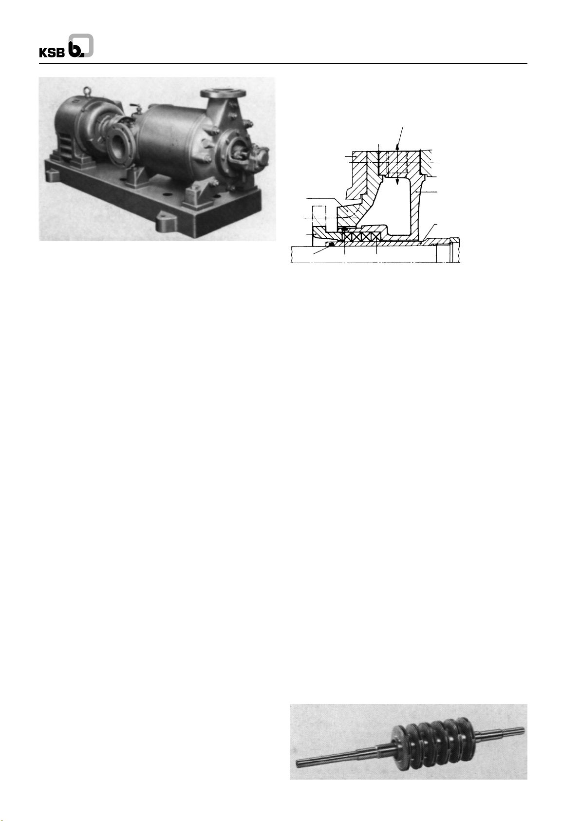
Fig. 1
0. Introduction
WK pumps are High Pressure Horizontal Centrifugal Pumps.
In accordance with the latest state of the art of pump design
and construction, our pumps combine favourable hydraulic
characteristics with a long service life, reliability of operation
and simple maintenance and operation.
A pre-requisite for trouble-free operation of the pumps is the
careful observance of the recommendations contained in this
operating instruction manual. It should therefore, always be at
the disposal of the personnel entrusted with the erection,
maintenance and operation of the pump.
It goes without saying that the pumps should only be operated
under the duty conditions specified (see data sheet). The terms
of our Guarantee naturally apply within this range of conditions.
Our Guarantee will become invalid if the pumps are dismantled,
either completely or partially, without our prior consent. The
first assembly and dismantling of the pump should be carried
out by skilled fitters and erectors, and this also applies to the
initial start-up (commissioning) of the pumping set.
400.3
350
165
452
412.3 412.4 461.1
400.3
451
524.2
(524.1)
Fig. 2 Stuffing box housing with cooling compartment cover
Depending on the number of stages and on the temperature
of the product pumped, the pump feet are integrally cast onto
the suction and discharge casings (106 and 107) either at the
bottom, or at shaft centerline height. The suction nozzle can
be arranged to point horizontally to the left or right hand side,
or vertically upwards, if the pump feet are arranged at the
bottom of the pump; if they are arranged at shaft centerling
height, the suction nozzle can only be arranged to point
vertically upwards the discharge nozzle points radially upwards
on both types of pump feet arrangement.
In order to achieve a favourable NPSH required, the suction
nozzles on all sizes of pumps are made one nominal size larger
than the discharge nozzles. The flange construction is specified
in the data sheet.
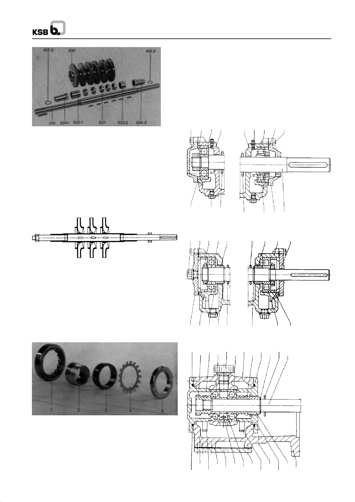
1.2 Rotor
All the rotating components assembled on the shaft make up
the complete pump rotor (See Fig. 3 and 4)
1. Pump Construction
(For item numbers, see under section 16, Sectional drawings.)
1.1 Casing
WK high pressure centrifugal pumps are single or multistage
centrifugal pumps with a radially split casing. This consists of
the suction and discharge casing (106 and 107) together with
a number of stage casings (108). If the extraction of a given
quantity of the liquid pumped at one of more intermediate
pressures is required, the corresponding stage casings can
be provided with extraction (Bleed off) nozzles. The individual
casing components are sealed off against one another by flat
gaskets (400.2) or by ‘O’ rings (412) and clamped together by
connection rods (905). The diffusers (171.1 and 171.2) are
arranged in the stage casings and in the discharge casing
respectively (108 and 107 respectively). They are centered in
the casings at their outer periphery and secured against
twisting.
The stuffing box housings (451) and bearing housing (350)
are flanged onto the suction and discharge casing respectively
(106 and 107) and attached by studs (902.1). The stuffing box
housings (451) are sealed off from the suction and discharge
casings respectively (106 and 107) by a flat gasket (400.3).
On pumps fitted with special hot water stuffing boxes or with
mechanical seals, the shaft seal is surrounded by a cooling
The shaft (210) transmits the torque generated by the drive
onto the impellers. The impellers (230) are mounted is
sequence on shaft (210), and they all point in the same
direction. They are secured against twisting by keys.
The narrow clearance gap between impeller neck and casing
wearing ring (502) at the suction and discharge end of each
impeller prevents the equalization of presure between one
stage and the next.
The shaft (210) is protected inside the pump against attack by
the fluid pumped by means of spacer sleeve (525.1/2) and
distance bushes stage (521). The distance bushes/stage also
serve to locate the impellers axially on the shaft. The shaft
(210) is protected by the shaft protection sleeves (524.1/.2) in
the region of the shaft seal. These protection sleeves are
screwed onto shaft (210) by means of screw threads with
opposed hand to the direction of rotation of the shaft.
Fig. 3 Assembled rotor
1
WK
5412 and standard bearing bracket (No adaptor sleeve
provided on pump size 150).
End side : 1 deep groove ball bearing in accordance with DIN
625 and standard bearing housing (see Figs. 7 and 8).
Heavy Duty Bearing Construction :
Drive end : Same as atandard bearing construction. End
side : 2 matched angular contact ball bearings in accordance
with DIN 628; X arrangement and heavy duty bearing bracket
(see Fig. 9).
Fig. 4 Dismantled rotor
In order to balance the axial thrust, throttling passages are
arranged at the impeller necks at the suction and discharge
end of each impeller, and additional balancing holes are
provided in the impeller necks at the discharge end
(See Fig. 5).
A fixed bearing absorbs the residual axial thrust generated
and also locates the rotor in the axial position; in the standard
bearing construction, this bearing consists of a deep groove
ball bearing (321) and in the pump construction with heavy
duty bearing bracket, it consists of two angular contact ball
bearings (320).
Fig. 5 Rotor
1.3 Bearing Arrangement
WK pumps are fitted with different types of beaings and bearing
housing, depending on the differential head (generated
pressure) of the pump. In the case of low differential heads,
the standard bearing construction is provided. In the case of
higher total heads, the heavy duty bearing construction is
provided to absorb the increased residual thrust.
The pump manufacturer decides which type of bearing
arrangement shall be provided.
361 920.4 321 350 350 731.2 322 400.4 901.2
400.4
903.4
(13B)
507
507 52-1 360 210
Fig. 7 Bearing construction, size 40 to 125
400.4 920.4 350 525.4
903.12
361 543 321 932 507 932 322 543
507 525.4 350 360
Fig. 8 Bearing construction, size 150
Drive end
Fig. 6 Individual bearing components (drive end)
Part 1 = Outer race with cage and rollers
Part 2 = Adaptor Sleeve
Part 3 = Inner bearing race
Part 4 = Locking Washer
Part 5 = Withdrawal Nut
Standard Bearing Construction :
Drive end : 1 Cylindrical roller bearing in accordance with DIN
5412 (see Fig. 6) with adaptor sleeve in accordance with DIN
901.3 361 913 350.2 412.7 507
903.5
(
)
13B
412.7 644 644 360.2
543400.5
525.8160
901.4
720.3
(8B)
210
932508320320923
525.5
902.3
Fig. 9 Bearing construction with heavy duty bearing
bracket size 150.
2
WK
Standard Construction
Pump size 40 50 65 80 100 125 150
Drive end :
cylindrical roller bearing NU 206 K NU 207 K NU 207 K NU 208 K NU 208 K NU 210 K NU 410
designation in accordance C 3 C 3 C 3 C 3 C 3 C 3 C 3
with DIN 5412
Adaptor sleeve in
accordance with DIN 5412
Non Drive end :
Deep groove ball bearing
designation in accordance 6403/C 3 6404/C 3 6404/C 3 6405/C 3 6405/C 3 6405/C 3 6410/C 3
with DIN 625
Oil fill in litres 0.16 0.18 0.18 0.25 0.25 0.28 0.45
Heavy Duty Bearing Bracket
Pump size 40 50 65 80 100 125 150
Drive end :
cylindrical roller bearing NU 206 K NU 207 K NU 207 K NU 208 K NU 208 K NU 210 K NU 410
designation in accordance C 3 C 3 C 3 C 3 C 3 C 3 C 3
with DIN 5412
Adaptor sleeve in
accordance with DIN 5415
Non Drive end :
Angular contact ball bearing
Din 628, 7305 BG 7306 BG 7306 BG 7307 BG 7307 BG 7309 BG 7310 BG
matched pair, X arrangement
Manufacturer SKF
FAG
Oil fill in litres 0.65 0.70 0.70 0.90 0.90 1.2 1.2
H 206 H 207 H 207 H 208 H 208 H 210 ---
H 206 H 207 H 207 H 208 H 208 H 210 ---
7305 B. UA 7306 B. UA 7306 B. UA 7307 B. UA 7307 B. UA 7309 B. UA 7310 B. UA
Drive at both Ends
Pump size 40 50 65 80 100 125 150
Suction side :
cylindrical roller bearing NU 206 K NU 207 K NU 207 K NU 208 K NU 208 K NU 210 K NU 410
designation in accordance C 3 C 3 C 3 C 3 C 3 C 3 C 3
with DIN 5412
Adaptor sleeve in
accordance with DIN 5412
Discharge side :
Deep groove ball bearing
designation in accordance 6305/C 3 6306/C 3 6306/C 3 6307/C 3 6307/C 3 6308/C 3 6410/C 3
with DIN 625
Oil fill in litres 0.16 0.18 0.18 0.25 0.25 0.28 0.45
Fig. 10 Bearing end oil requirement table
In case of the pump construction with drive at both ends, the
bearing arrangement at the suction end corresponds to the
standard construction. At the discharge end, deep groove ball
bearings in accordance with DIN 625 are fitted, but they are of
bearing series 63.
See Fig. 10 ‘‘Bearing and oil requirement table’’ for precise
bearing designation and size for the individual pump sizes.
Splash ring (507) on shaft (210) prevent the penetration of
any leakage liquid from the stuffing box into the bearing
housing.
H 206 H 207 H 207 H 208 H 208 H 210 ---
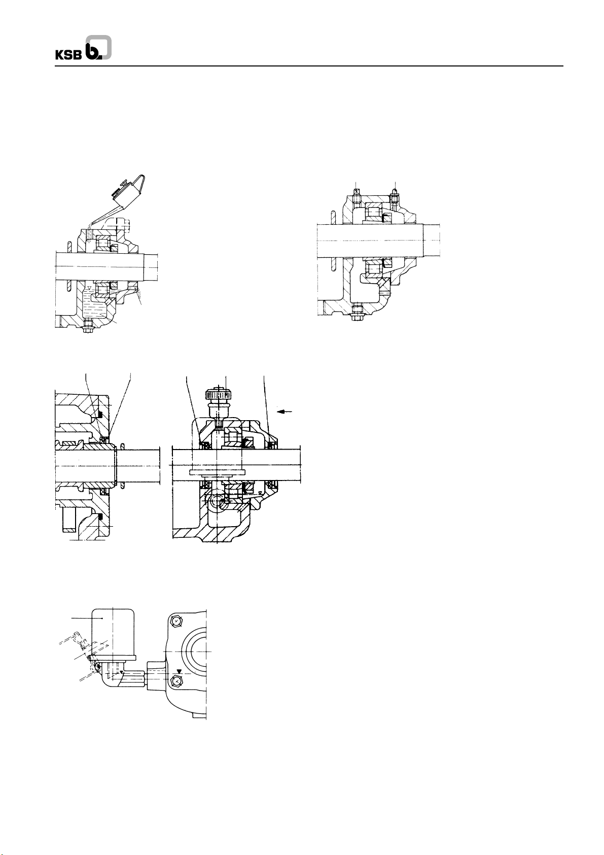
1.4 Lubrication
1.4.1 Oil Lubrication
Standard construction WK pumps are provided with oil splash
lubrication. The antifriction bearings are slightly submerged in
the oil sump, ensuring perfectly satisfactory lubrication at all
times. The max. oil level is automatically attained during topping
up when oil starts pouring out of the over-flow holes in the
bearing covers (360/361).
On request, we can fit constant level oilers (638), which will
necessitate the sealing of the shaft against the bearing bracket
by means of felt rings (422.1) (See Fig. 11 to 13).
3
WK
Oil Quality : Machinery oil possessing good air release
properties and corrosion prevention characteristics; kinematic
viscosity 36 cSt approx. = 4.80E at 500C; flash point 1500C
minimum; pour point lower than -200C.
Lubrication times : First oil change after the first 500 hours of
operation, subsequent oil changes after every 3000 hours of
operation approx., but at least once a year.
Overflow hole
Oil sump
Fig. 11 Oil splash lubrication
422.4
500.4
500.1 913 422.1
X
Portable (mobile) pumps, and pumps installed on board ship
have grease-lubricated bearings (See Fig. 14). Use a good
quality lithium soap ball and roller bearing grease, free of resin
and acid, and possessing rust preventive properties. The
grease should have a penetration number situated between 2
and 3, corresponding to a worked penetration situated between
2220 and 295 mm/10. Its drop point should be not less than
0
C.
175
731.2 636
Fig. 14 Grease lubricated bearing construction
The bearing temperature may be allowed to rise up to 400C
above room temperature, but should not exceed 800C. The
grease fill will last for 15000 hours of operation i.e., for 2 years
approx. If the operating conditions are arduous, the bearings
should be serviced once a year. A grease fill amounts to 10-20
grammes of grease, depending on the pump size. The pump
bearings are packed with grease at our Works before despatch.
End side
(Heavy duty bring bracket)
Drive end
Fig. 12 Construction with constant level oiler and sealing of
the bearing housing.
638
Fig. 13 Constant level oiler viewed from X
Topping up of the oil fill at least once a month.
The bearing temperature may be allowed to rise up to 40
0
above room temperature, but should not exceed 800C.
1.4.2 Grease Lubrication
(Cannot be provided on heavy duty bearing construction
pumps).
1.5 Shaft Seal
The shaft is sealed at its exits through the casings by softpacked
stuffing boxes or by mechanical seals. If the pump is fitted with
special stuffing boxes, mechanical seals can be fitted in lieu of
soft packing (or vice versa) at any time during the service life
of the pump, with a minimum of machining of the cooling
compartment covers. On the other hand, the fitting of
mechanical seals to pumps equipped with standard or hot water
type soft-packed stuffing boxes necesitates the fitting of new
pump components. Particulars can be obtained from the pump
manufacturer.
1.5.1 Stuffing Boxes
Soft-packed stuffing boxes reduce the flow of leakage liquid at
the clearance gap between casing and shaft protection sleeve
when the pressure inside the pump is higher than atmospheric.
Conversely, on pumps which operate on suction lift, the softpacked stuffing box prevents the ingress of air into the pump.
Sealing is effected by means of soft packing (461.1) arranged
in a number of rings in the annular space between the stuffing
box housing (451) and the shaft protection sleeve (524.1/2)
and lightly compressed by the stuffing box gland (452).
Caution : On pumps which have a high discharge pressure,
the stuffing box at the discharge end is relieved of pressure,
via a balance liquid line, down to the suction pressure, provided
that the differential pressure across the pump exceeds 20 bar.
This ensures that the stuffing boxes at the suction and discharge
ends of the pump have the same admission pressure. This
arrangement applies to pump sizes 40 to 65 if the discharge
C
pressure exceeds 20 bar and to pump sizes 80 to 150 if the
discharge pressure exceeds 15 bar.
Single stage pumps require no special pressure relief even at
high discharge pressures. The pressure is relieved via the
balance holes in the impeller.
4
WK
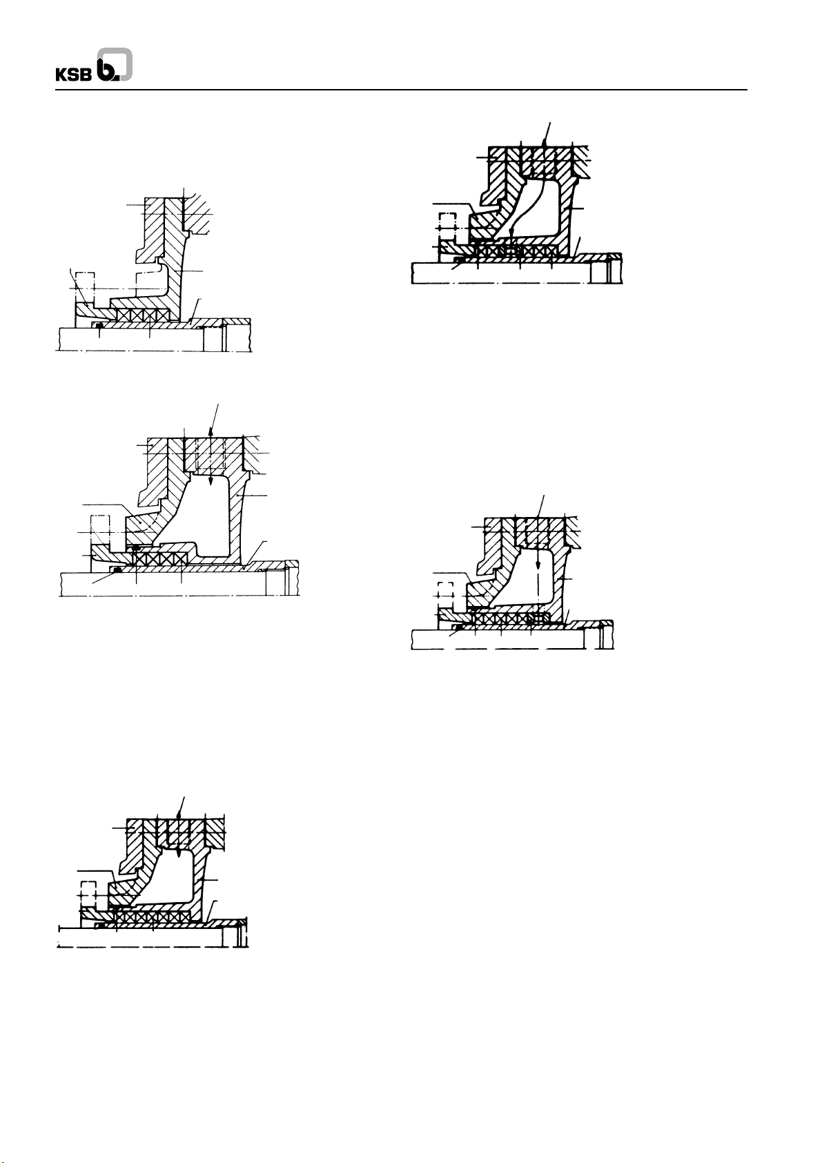
Soft-packed stuffing box, ‘‘Standard’’ (N) construction.
Standard construction with 4 packing rings (461.1) used for
temperatures of the fluid pumped up to 1050C. The stuffing
box compartment cannot be cooled.
400.3
350
452
412.3
461.1
451
524.2
(524.1)
Fig. 15 ‘‘Standard’’ (N) construction stuffing box
7A/7E
400.3
350
165
452
412.3 412.4 461.1
400.3
451
524.2
(524.1)
Fig. 16 ‘‘Hot Water’’ (HW) construction stuffing box
Soft-packed stuffing box, ‘‘Hot Water’’ (HW) construction.
Construction with 4 packing rings (461.1) and cooling of the
stuffing box compartment. Used for temperatures of the fluid
pumped in excess of 105
0
C up to 2300C max.
Special stuffing box, ‘‘Extra-deep’’ (V) construction.
Construction with 7 packing rings (461.1) and cooling of the
stuffing box compartment, used mainly in process industry
applications.
7A/7E
400.3
451
524.2
(524.1)
165
452
412.3
400.3
350
412.4 461.1
Fig. 17 Special soft packed stuffing box ‘‘Extra deep’’ (V)
Special stuffing box, ‘‘VSM’’ Constructed
VSM is the abbreviation (in German) of ‘‘Extra deep with lantern
ring at the centre’’.
Construction with 5 packing rings (461.1) and one seal case
ring (458) arranged at the centre of the packing compartment;
used mainly for operation under vacuum or suction lift, and
where malodorous fluids are pumped. For operation under
vacuum, the lantern ring (458) is fed with a sealing liquid, and
it prevents the ingress of air into the pump.
10A/10E
400.3
350
165
452
412.3 412.4 461.1
458
400.3
451
524.2
(524.1)
Fluids pumped :
Operation under vacuum
or pumping of malodorous
fluids (ammonia and
solvents).
Sealing liquid consumption
1 to 3 litres/hours approx.
Fig. 18 Special stuffing box VSM
Special stuffing box, ‘‘VSH’’ constructed.
VSH is the abbreviation (in German) for ‘‘Extra deep with seal
cage ring at the bottom of the box’’. The construction with 5
packing rings (461.1) and a seal cage ring (458) arranged at
the bottom of the packing compartment is used where fluids
containing abrasive particles are pumped. The flushing liquid,
which should be fed through the cage ring (458) at a pressure
of at least 1 to 4 bar (max.) above the suction pressure,
penetrates inside the pump and protects the stuffing box
packing (461.1) against abrasive substances.
11E
458
400.3
451
524.2
(524.1)
Fluids :
Products containing abrasive
particles, which must be kept
away from the stuffing box
packing, so as not to erode
the latter (oils containing
diatomite (kieselguhr),
fractions from catalytic
cracking containing abrasive
catalyst particles).
Flushing liquid consumption
300 to 500 litres/hour approx.
165
452
412.3
400.3
350
412.4 461.1
Fig. 19 Special stuffing box VSH.
1.5.1.1 Cooling Liquid for Stuffing Boxes
Treated cooling water which does not tend to precipitate salts
causing hardness out of solution should be used as cooling
liquid. The cooling water should be allowed to flow out freely
and visibly, so that it can be checked at any time in respect of
rate of flow and temperature. The temperature differential
between cooling water inlet and outlet should not exceed 10
The max. permissible cooling water outlet temperature should
not exceed 500C. The cooling water pressure should be situated
between 1 bar min. and 10 bar max.
An isolating valve should be incorporated in the cooling water
supply line, to enable the rate of flow of cooling water to be
adjusted, and the supply of cooling water to be turned off when
the pump is shut down. The cooling water should only be turned
off after the temperature of the fluid inside the pump has
dropped to below 80
0
C.
1.5.1.2 Packing the Stuffing Boxes
Caution : The pump is despatched from our works with the
stuffing boxes unpacked. An adequate quantity of packing
material is supplied loose with the pump. The stuffing box will
only be able to perform its vital function satisfactorily on
condition that it is carefully packed and properly maintained
as prescribed.
Before packing, thoroughly clean stuffing box gland (452),
packing compartment and shaft protection sleeve (524.1/.2).
5
0
C.

Fig. 20 Cutting the packing rings of length.
To cut the packing rings to correct length, use a suitable wooden
cutting jig (we can supply same on request), to ensure that the
packing rings are of the correct length and that their ring butts
come into correct contact with one another (see Fig. 20).
WK
Fig. 23 Tightening the stuffing box gland
Fig. 21 Stuffing box packing
If the packing rings are either too long or too short, the stuffing
box will not be able to perform its function properly. In the case
of asbestos-graphite packing material, the rubbing faces of
the individual rings should be lightly coated with molybdenum
disulphide before insertion in the packing compartment. The
first packing ring is then inserted and pushed home into the
compartment with the aid of the stuffing box gland.
The following packing rings are then inserted into the packing
compartment one by one, making sure that the butt joint of
each ring is offset 90
0
approx. in relation to the butt joint of the
preceding ring; the individual rings are pushed home into the
packing compartment with the aid of the stuffing box gland
(see Fig. 21 and 22). The packing rings should only be pressed
lightly against one another. They should not be inserted in the
packing compartment in such a way that a clear gap of 6 to 8
mm is left at the outer end of the compartment for the positive
guidance of the stuffing box gland.
Fig. 24 Information plate regading seal cage ring
The inserted packing rings should then be compressed
moderately with the aid of the stuffing box gland (452) and the
nuts (see Fig. 23). Then the nuts should be slackened again
by one to two complete turns, and thereafter tightened lightly
by hand. The correct and even seating of the stuffing box gland
(452) should be checked when the pump is subjected to suction
pressure, by inserting a feeler gauge between the gland (452)
and the shaft protection sleeve (524.1/.2).
In the case of the special stuffing boxes, a seal cage ring is
also inserted in the packing compartment, viz. at the centre of
the compartment (between the packing rings) in the case of
construction ‘‘VSM’’, and at the bottom of the compartment in
the case of construction ‘‘VSH’’. In these cases, an information
plate (see Fig. 20) is affixed to the stuffing box housing, showing
the position of the lantern ring. The seal cage ring must register
beneath the drilled hole in the stuffing box housing, to enable
the sealing of flushing liquid to flow through the hole and the
ring. The sealing or flushing liquid pressure should be 1 to 4
bar above the pressure reigning in the packing compartment
of the stuffing box.
Fig. 22 Insertion of packing rings with the aid of the stuffing
box gland
The packing of the stuffing boxes should be carried out with
great care, to avoid an excessively high radial pressing force
of the packing rings against the shaft protection sleeve, which
might damage the latter. If the shaft protection sleeve is scored
or grooved, even a new packing cannot be expected to last
very long in service.
6

A newly packed stuffing box should leak profusely at first. If
this leakage does not cease of its own accord after a relatively
short period of operation, the nuts on the gland should be
tightened slowly and evenly while the pump is running, until
the stuffing box only drips tightened evenly and not askew, as
otherwise the shaft protection sleeves (524.1/.2) might be
damaged (see Fig. 23).
The leakage rate in service of a soft-packed stuffing box should
amount to 3 to 5 litres/hours approx.
If the newly packed stuffing boxes start to smoke when the
pump is started up for the first time, the pump should be
switched off. If the smoking persists after the pump has been
started up again and operated several times in succession,
the nuts on the gland should be slackened slightly, or the stuffing
box should be inspected if necessary.
WK
Fig. 31 Mounted spacer-type flexible coupling
1.5.1.3 Packing Material
When selecting the packing material, make sure it is compatible
with the fluid pumped (consult the manufacturer in case of
doubt).
In steam generating plants, the asbestos-graphite packing
material specially developed for hot water service has given
good results. Packing material which has been dept in store
for a certain period has a longer service life than packing
material fresh from the packing manufacturer.
1.5.2 Mechanical Seals
Mechanical seals can be fitted as shaft seals in lieu of softpacked stuffing boxes. If it is intended to replace soft-packed
stuffing boxes by mechanical seals after the pump has been
in service for some time, it is necessary for the pump to be
equipped with stuffing box holdings (451) for ‘‘V’’ special stuffing
boxes. It is also necessary to re-machine two tapped holes in
the cooling cover (165) for the attachment of the seal cover
(471).
1.6 Coupling
The pump on connected to the driver by a flexible coupling.
Fig. 29 illustrated the type of coupling most frequently used.
2. Mode of Operation of Pump
The fluid flows through the suction casing towards the impeller
at a given pressure. Energy is transmitted to the fluid by the
impeller, which is fitted with vanes. From the impeller, the fluid
flows into the diffuser, where kinetic energy is converted into
potential energy, increasing the pressure rise still further.
The return guide vanes arranged on the discharge end cheek
of the diffuser (171.1) guide the fluid under hydraulically
favourable conditions towards the eye of the following stage
impeller (230). This process is repeated from one stage to the
next, and the pressure rise by the same amount in each stage,
viz. by the stage generated pressure. After leaving the final
stage diffuser (171.2), the fluid flows through the discharge
casing (107) into the discharge line connected to this casing.
The generated pressure creates an axial thrust on the pump
rotor of single and multistage centrifugal pumps. By the
provision of narrow throttling gap between the impeller necks
and the casing wearing rings at either side of each impeller,
equal size lateral impeller space, and therefore almost identical
pressure conditions are created at the suction and discharge
ends of each impeller (see Fig. 34).
Fig. 29 Flexible coupling
Spacer type couplings (see Figs. 30 and 31) enable inspections
and minor repairs (e.g. the fitting of new bearings or shaft
protecting sleeves) to be carried out without removing the driver.
Fig. 30 Spacer type flexible coupling
Balance hole
Fig. 34 Axial forces acting on impeller
The balance holes in the discharge side impeller cheeks ensure
a compensation of pressures between the suction and
discharge sides of the impellers in the region situated between
the impeller hub and the throttling gap, thus again preventing
the creation of any appreciable axial thrust in this region of the
impeller. Any residual axial thrust is absorbed by the fixed
bearing in the discharge end bearing housing. This fixed
bearing also locates the axial rotor position.
7
WK
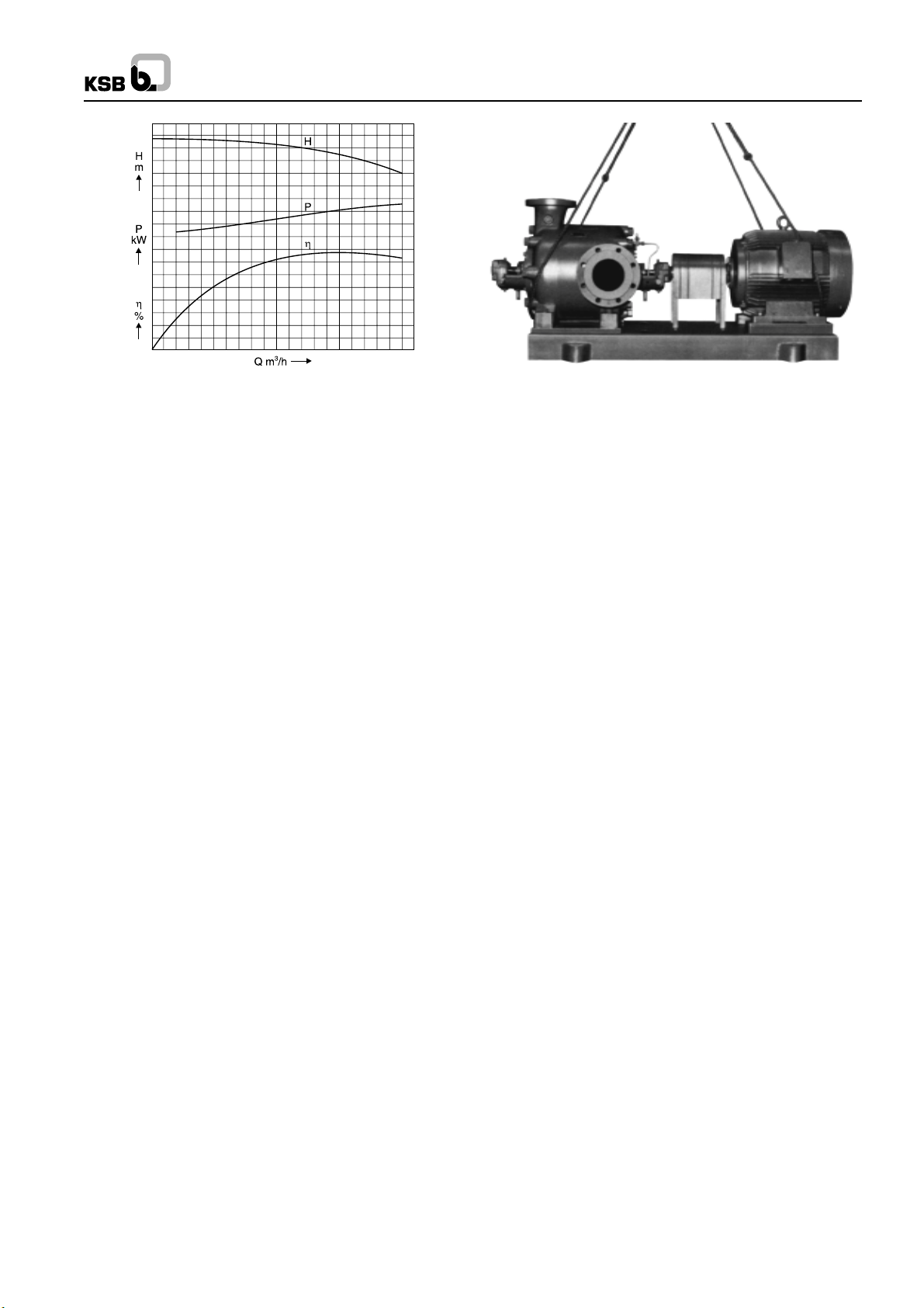
Fig. 35 Characteristics for constant pump rotational speed
As can be seen in the Fig. 35 the power absorbed by the pump
does not decrease proportionately with decreasing rate of flow,
but remains relatively high at the pump shut-off point (capacity
Q = 0).
This absorbed power is almost wholly converted into heat inside
the pump and this heating up process can lead to rapid
evaporation of the fluid inside the pump, particularly if the driving
motor is powerful and the fluid pumped is hot; this happens at
the pump shut-off point (Q = 0) and at very low rate of flow.
In order to avoid such evaporation which might damage the
pump, It is necessary to ensure a given minimum rate of flow
through the pump at all times, which removes the heat
generated.
For this purpose, an automatic recirculation valve (combined
with a non-return valve) is provided (see section 9.3.1); this
valve automatically opens a by-pass line when the rate of flow
drops below a given preset value. If such a valve is not
incorporated in the plant, the pump must not be operated below
a given minimum rate of flow, nor must it be allowed to run
against a closed discharge valve. After start up against a closed
discharge valve, the latter should be opened immediately. If
the pump handles a hot fluid or a fluid with a low boiling point
(highly volatile), or if it operates on suction lift, steps must be
taken to ensure that the fluid at the pump inlet nozzles has
attained the pressure prescribed in the Confirmation of Order,
in order to prevent vapour formation and the resulting damage
caused by cavitation particularly the disintegration of the first
stage impeller). If the back pressure is too low, the capacity of
the pump will increase unduly, and the danger than arise of
overloading and overheating of the driving motor.
Fig. 36 Slinging the ropes under the pump and driver
mounted on a combine baseplate
5. Painting
Standard construction pumps operating at temperatures below
1400C are provided with a coat of primer and a top coat of
synthetic resin base blue enamel paint (RAL 5001). If the
operating temperature exceeds 1400C, the ‘‘hot’’ pump
components, i.e. casing, pressure gauge piping and connection
rods are provided with a coat of aluminium bronze paint (RAL
9006 silver bronze). All the ‘‘Cold’’ pump components, viz. the
base-plate, bearing brackets etc. receive a coat of primer and
a top coat of blue enamel paint (RAL 5001).
Special painting to customer’s specification can be carried out
on request in accordance with the Confirmation of Order. All
bright aprts and surfaces on the pump are coated with oil
grease.
6. Condition of Equipment as Supplied
The following constructions can be supplied on request (see
Confirmation of Order for certified and binding data) :
1. Pump without baseplate (Fig. 0).
2. Pump mounted on short baseplate (Fig. 4).
(designed to accomodate pump only)
3. Pump and driver mounted on combbined baseplate
(Fig. 3).
If the pump is supplied with a short baseplate or without a
baseplate, the ropes should be slung under the connection
rods as illustrated in Fig. 37.
3. Drive
The driver is usually connected to the stub shaft at the suction
end of the pump. The direction of rotation is clockwise viewed
from the driver into the pump. On request, the drive can be
arranged at the discharge end of the pump (direction of rotation
anticlockwise) or the pump can be provided with a stub shaft
at both ends.
There are too many different types of drivers to allow them to
be described in detail here, and we would therefore refer you
to the operating instructions for the driver, published by the
driver manufacturer, which are attached.
4. Transport
If the pump is supplied as a unit bolted onto a baseplate, the
ropes for handling and transport should be slung under the
pump and driver as illustrated in Fig. 36.
Caution : When slinging the ropes for transport, never sling
them under the pump stub shafts or under the bearing brackets.
The internal interconnecting piping for the pressure relief of
the shaft seal, and any cooling liquid supply and drain lines or
sealing liquid lines, in so far as required, are already laid at
our works prior to despatch, up to the limit of the Extent of
Supply. The coupling and coupling guard are already mounted
on the pump.
When a pump is supplied mounted on a combined baseplate,
only the pump is dowelled to the baseplate, after having been
aligned with the driver.
The driver is dowelled on site with cylindrical dowel pins after
the final alignment on site. The necessary cylindrical dowel
pins are supplied loose with the pump.
8
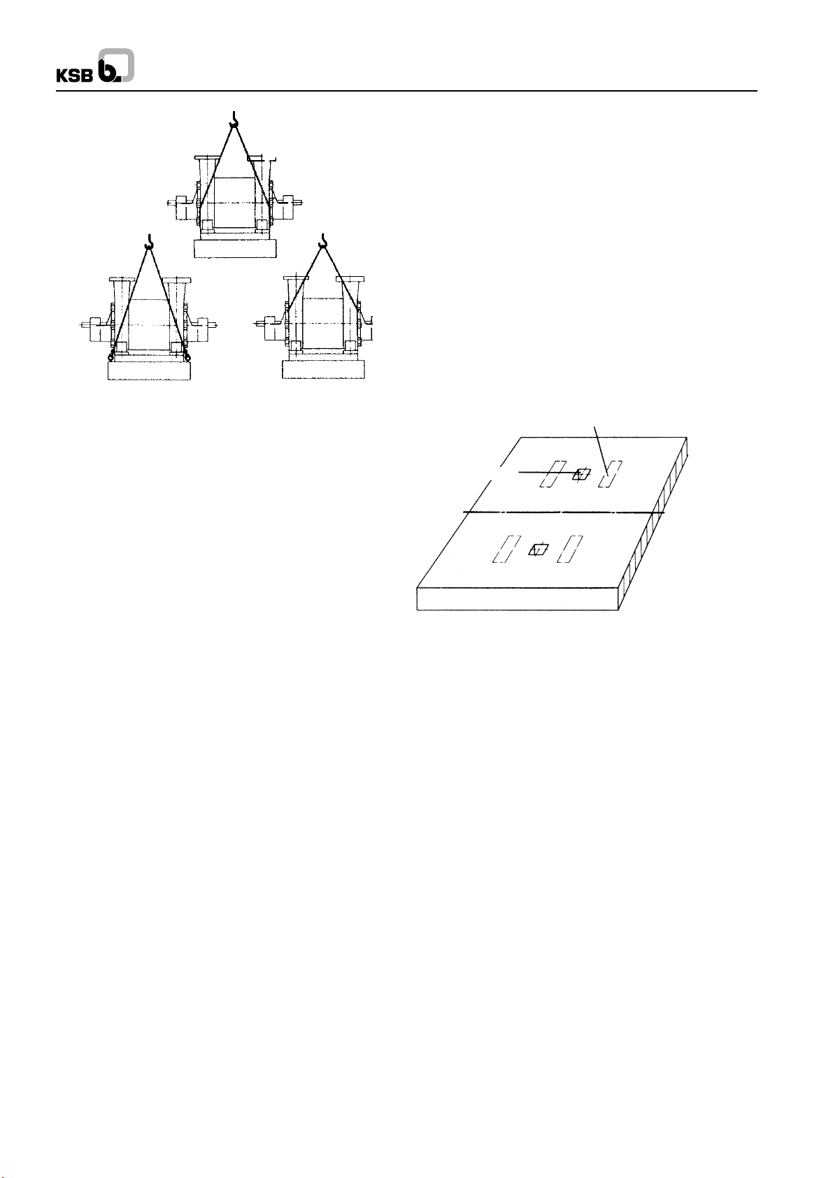
Fig. 37 Slinging the ropes on a pump with short baseplate
Fig. 4
WK
Our erection staff will check the correct orientation of the
foundations in relation to the space axis after c;earamce fpr
erection has been given. The site management is responsible
for the zero point marking of the foundation (see ‘‘Conditions
of Erection’’).
The areas for the packing plates (shims) should now be marked
out and trued up in accordance with the foundation drawing.
Then thick packing plates should be laid in position and levelled
up with a spirit level.
The packing plates should lie flush on the foundation and be
levelled up as truly horizontal as possible to facilitate the
subsequent alignment and levelling up of the complete pumping
set as accurately as possible. The exact height is of less
importance at this stage, because any difference in heights
can be compensated by the insertion of shims of varying
thickness when the set itself is levelled up. Three point support
should be adopted for the preliminary levelling up.
Surface for shims (packing plates)
Caution :
1. The pump bearings are not filled with oil.
2. The stuffing boxes are not packed.
All apertures are plugged with PVC stoppers.
7. Accessories
As a general rule, the following items are supplied loose with
the pump :
1 set of binding bolts (only supplied loose if the pump is supplied
without a baseplate).
1 set of foundation bolts (if the pump is supplied with a
baseplate).
On request, the following items can be supplied, amongst
others :
Pressure gauge holder or pressure gauge bridge
Pressure gauge
Pressure vacuum gauge
Stop valve for pressure gauge
Coupling extractor device
1 set of shims and packing plates for levelling up
1 wooden cutting jig for packing rings
1 set of special tools
8. Installing the Pumping Set
Foundation bolt
Foundation axis
Fig. 38 Preparation of foundation
8.2 Installation and preliminary Levelling Up
The pumping set should only be placed on the foundation after
the latter has set quite firmly, and the preparations for the
foundation described above should be carefully followed.
Before placing the set on the foundation, suspend the
foundation bolts in the baseplate. Then fix the longitudinal and
lateral directions and the correct height, then carry out a
preliminary levelling up with the aid of a spirit level, and grout
in the foundation bolts.
8.3 Aligning the Coupling
If the bare pump only is supplied, i.e. the motor or gearbox are
not mounted, the flexible coupling should be pre-heated to 100-
0
C approx. in an oil bath before mounting on the stub shafts.
120
The flexible elements should be removed beforehand.
8.1 Description of Site prior to Commencement of
Erection
When our erection staff arrive on site, the pump foundation
must have been checked for dimensional conformity with our
foundation drawing data by the site management, and cleared
for erection to preceed. The foundation and its immediate
surroundings must be in a suitable condition to enable the
efficient and speedy erection of the pump and accessories to
proceed with out hindrance.
Our erection staff must be able to make use of customer’s
hoisting gear, e.g. the engine room crane etc. for transport
and erection if required.
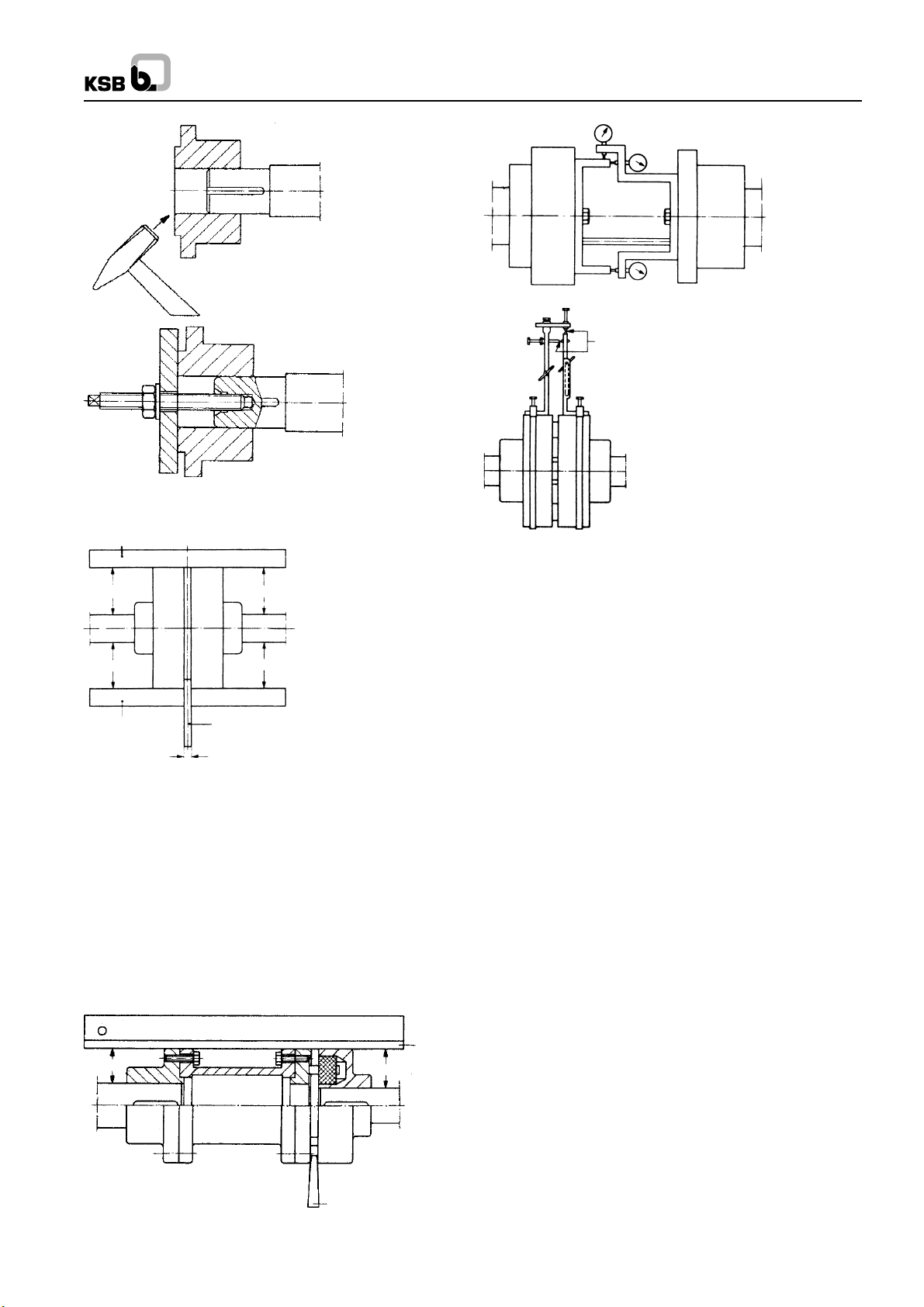
Caution : Never drive the half coupling onto the shaft by
hammer blows. Always use a pusher device to mount it on the
shaft. (see Fig. 39).
In order to align the shafts, the pump and driver should be
pushed towards each other until the two coupling halves are
separated by the axial gap specified in the foundation or
installation drawing.
The preliminary alignment of the coupling is effected by means
of a short steel straight edge and feeler gauge.
9
WK
Wrong
Right
Fig. 39 Mounting the coupling
Straight edge
A
B
C
Max. clearance 0.04 mm
Fig. 42 Coupling alignment jig
Spacer type coupling
a
1
ab
Straight edge Gauge
E
b
1
Fig. 40 Aligning the coupling bby means of a straight edge
and gauge
Check the axial gap ‘‘E’’ at various points around the periphery,
with the aid of a feeler gauge, and place a short straight edge
across the outer diameter of the two coupling havles, forming
bridge. If the gap ‘‘E’’ remains constant around the periphery,
and if the straight edge lies flush at all points, the preliminary
alignment can be considered satisfactory (see Fig. 40 and 41).
The accurate coupling alignment requires the manufacturer of
a coupling alignment jig. This can be made from 20 x 20 flat
bar steel or similar, the jig should be attached to the shafts
(see Fig. 42).
Straight
D
edge
D
The coupling can be considered correctly aligned with the aid
of the jigs illustrated if the difference measured does not exceed
0.04 mm both in the radial and axial directions, measurements
being taken in 4 planes at 90
0
intervals. The coupling alignment
check should be repeated after the piping has been connected
to the pump.
8.4 Grouting in the Baseplate
After alignment of the coupling, the holes for the foundations
bolts and the baseplate should be grouted in with a quicksetting
cement mortar in 1:2 ratio (1 part of cement on 2 parts sand
and gravel). Make sure that all the boxes in the baseplate are
completely filled with the cement mortar and that no cavities
remain.
The foundation bolts should be tightened evenly and firmly
after the grout has set firmly. Then check with the aid of a dial
micrometer that the alignment is still correct.
8.5 Final Alignment
After all the pipelines have been connected and the direction
of rotation check has been carried out (with the pump
disconnected from the driver), the final alignment of the
pumping set should be effected. The same procedure would
be followed as for the preliminary alignment, i.e. the relevant
alignment jigs with 3 dial micrometers should be used and the
measurements previously described should be carried out at
the various shaft position (see section 8.3 ‘‘Aligning the
Couplings’’).
Gauge
Fig. 41 Aligning the spacer-type coupling by means of a
straight edge and gauge
Caution : The pump feet must be pulled tight against their
seating on the baseplate. The alignment can be considered
satisfactory if the dimensional deviations do not exceed 0.04
mm both in the case of the radial measurement and in the
case of the axial difference measurement (see section
‘‘Alignment’’).
The final measurement readings should be entered in the
system of coordinates on the erection check list. Any necessary
height adjustments should be effected by inserting shims of
appropriate thickness under the feet of the individual machines.
10
9. Piping
The main piping should be connected to the pump without
transmitting any stresses or strains onto the latter. Any
appreciable piping forces which are transmited to the baseplate via the PUMP can detrimentally affect the alignment and
the running of the pump. Such forces should therefore be kept
to a minimum at all costs.
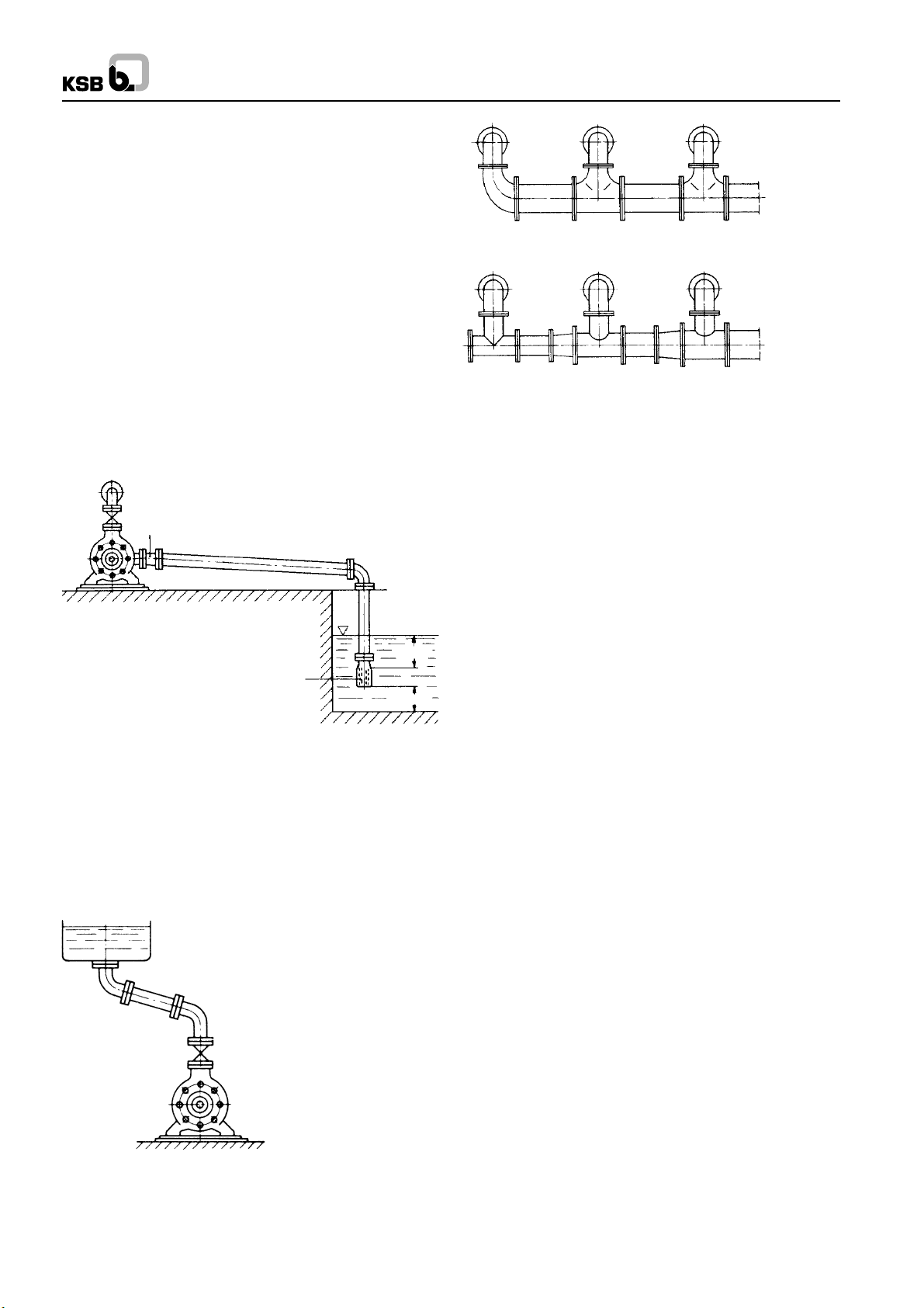
9.1 Suction Lift Line and Positive Suction Head Line
The pipe line connected to the suction casing (106) is called
either a suction lift line or a (positive) suction head line,
depending on whether the pressure at the pump inlet is below
or above atmospheric pressure. This line should be kept as
short as possible. (see Figs. 43 and 44)
Suction lift lines should rise all the way towards the pump,
they should also be absolutely leak tight and be laid in such a
way as to prevent the formation of air pockets at any point.
(see Fig. 43).
Eccentric reducer (fitted belly down)
>0.5m
Suction strainer basket
>0.5m
Fig. 43 Suction lift line
The nominal size of the pump suction flange is no accurate
guide to the size of the suction lift line. The latter should be
sized, as a first approximation to give a velocity of 2m/sec.
approx. In principle, every pump should be equipped with its
own individual suction lift line. If this is not feasible for particular
reasons, the common suction lift line should be sized for a s
low a velocity as possible and preferably for a constant velocity
right up to the last pump on the line (see Fig. 45).
WK
Correct
Wrong
Fig. 45 Common suction lift line for several pumps
In addition, pumps connected to a common suction lift line
should be equipped with VSM stuffing boxes.
If the suction lift line is buried, it should be hydrostatically tested
at 3 to 4 bar before burial.
The same remarks as above apply to the nature and laying of
(positive) suction head lines. Horizontal lenngths of suction
head lines should however be laid with a slightly rising slope
towards the suction vessel. If it is not feasible to avoid apexes
in the suction head line, each apex should be equipped with a
vent cock. It is also advisable to avoid any appreciable length
of horizontal suction head line laid close beneath the suction
vessel because of the danger of evaporation (see Fig. 44).
9.1.1 Strainers in Suction Head Line/Suction Lift Line
Before a new pumping installation is commissioned, all the
vessels, piping and connections should be thoroughly cleaned,
flushed through and blown though. It often happens that welding
beads, pipe scal and other dirt only become detached from
inside the piping after a considerable period of service; they
must therefore be prevented from penetrating inside the pump
by the provision of a strainer in the suction head or suction lift
line. This strainer should have a free area of holes equal to 3
times the pipe cross section area approx., in order to avoid an
excessive pressure drop when foreign bodies tend to clog the
strainer.
Conical (hat shaped) strainers have given good results in
service (see DIN 4189), they should have a woven wire insert
of corrosion-resistant material with a 1.0 mm. mesh width of
0.5 mm. diameter wire. The fine strainer should precede the
coarse strainer in respect of direction of flow of the fluid. During
the initial period of commissioning, the suction pressure should
be kept under frequent observation. If the NPSH available is
found to decrease, this may be due to clogged strainers (the
pressure drop acros the strainer should be measured with the
aid of a differential pressure gauge). The strainers should then
be cleaned. (see Figs. 46 and 47).
Fig. 44 Suction head line
Unless anything to the contrary has been specified, the max.
permissible pressure drop across the strainer should not
exceed 3 meters.
11
 Loading...