

Page 1
Hygienic Pump in Close-coupled Design
Vitachrom
Installation/Operating Manual
Page 2

Legal information/Copyright
Installation/Operating Manual Vitachrom
Original operating manual
All rights reserved. The contents provided herein must neither be distributed, copied, reproduced,
edited or processed for any other purpose, nor otherwise transmitted, published or made available to a
third party without the manufacturer's express written consent.
Subject to technical modification without prior notice.
© KSB SE & Co. KGaA, Frankenthal 13/07/2018
Page 3

Contents
3 of 72
Vitachrom
Contents
Glossary .................................................................................................................................................. 5
1 General.................................................................................................................................................... 6
1.1 Principles ...........................................................................................................................................................6
1.2 Installation of partly completed machinery....................................................................................................6
1.3 Target group.....................................................................................................................................................6
1.4 Other applicable documents............................................................................................................................6
1.5 Symbols .............................................................................................................................................................6
1.6 Key to safety symbols/markings.......................................................................................................................7
2 Safety...................................................................................................................................................... 8
2.1 General..............................................................................................................................................................8
2.2 Intended use .....................................................................................................................................................8
2.3 Personnel qualification and training...............................................................................................................8
2.4 Consequences and risks caused by non-compliance with this manual .........................................................9
2.5 Safety awareness ..............................................................................................................................................9
2.6 Safety information for the operator/user.......................................................................................................9
2.7 Safety information for maintenance, inspection and installation ................................................................9
2.8 Unauthorised modes of operation................................................................................................................10
2.9 Explosion protection ......................................................................................................................................10
2.9.1 Marking ..............................................................................................................................................10
2.9.2 Temperature limits.............................................................................................................................10
2.9.3 Monitoring equipment......................................................................................................................11
2.9.4 Operating limits .................................................................................................................................11
3 Transport/Temporary Storage/Disposal............................................................................................. 12
3.1 Checking the condition upon delivery..........................................................................................................12
3.2 Transport.........................................................................................................................................................12
3.3 Storage/preservation......................................................................................................................................12
3.4 Return to supplier...........................................................................................................................................13
3.5 Disposal ...........................................................................................................................................................14
4 Description of the Pump (Set)............................................................................................................. 15
4.1 General description ........................................................................................................................................15
4.2 Designation.....................................................................................................................................................15
4.3 Name plate......................................................................................................................................................17
4.4 Design details..................................................................................................................................................17
4.5 Mounting arrangements................................................................................................................................19
4.6 Configuration and function...........................................................................................................................20
4.7 Noise characteristics .......................................................................................................................................20
4.8 Scope of supply...............................................................................................................................................21
4.9 Dimensions and weights ................................................................................................................................21
5 Installation at Site................................................................................................................................ 22
5.1 Checks to be carried out prior to installation...............................................................................................22
5.2 Installing the pump set ..................................................................................................................................22
5.2.1 Removing the transport lock.............................................................................................................22
5.2.2 Installing the pump set......................................................................................................................24
5.3 Piping ..............................................................................................................................................................24
5.3.1 Connecting the piping.......................................................................................................................24
5.3.2 Permissible forces and moments at the pump nozzles....................................................................25
5.3.3 Vacuum balance line..........................................................................................................................25
5.3.4 Auxiliary connections.........................................................................................................................26
5.4 Enclosure/insulation .......................................................................................................................................27
5.5 Electrical connection ......................................................................................................................................27
5.5.1 Setting the time relay........................................................................................................................28
5.5.2 Connecting the motor .......................................................................................................................28
Page 4

Contents
4 of 72
Vitachrom
5.5.3 Earthing..............................................................................................................................................28
5.6 Checking the direction of rotation................................................................................................................28
6 Commissioning/Start-up/Shutdown................................................................................................... 30
6.1 Commissioning/Start-up.................................................................................................................................30
6.1.1 Prerequisites for commissioning/start-up .........................................................................................30
6.1.2 Priming and venting the pump.........................................................................................................30
6.1.3 Start-up...............................................................................................................................................31
6.1.4 Checking the shaft seal......................................................................................................................32
6.1.5 Shutdown ...........................................................................................................................................32
6.1.6 Quench liquid supply.........................................................................................................................32
6.2 Operating limits..............................................................................................................................................33
6.2.1 Ambient temperature........................................................................................................................33
6.2.2 Frequency of starts.............................................................................................................................34
6.2.3 Cleaning in place (CIP).......................................................................................................................34
6.2.4 SIP (steaming in place).......................................................................................................................34
6.2.5 Fluid handled .....................................................................................................................................35
6.3 Shutdown/storage/preservation ....................................................................................................................36
6.3.1 Measures to be taken for shutdown ................................................................................................36
6.4 Returning to service .......................................................................................................................................37
7 Servicing/Maintenance........................................................................................................................ 38
7.1 Safety regulations...........................................................................................................................................38
7.2 Servicing/Inspection........................................................................................................................................39
7.2.1 Supervision of operation...................................................................................................................39
7.2.2 Inspection work..................................................................................................................................41
7.3 Drainage/cleaning ..........................................................................................................................................42
7.4 Dismantling the pump set..............................................................................................................................42
7.4.1 General information/Safety regulations...........................................................................................42
7.4.2 Preparing the pump set.....................................................................................................................43
7.4.3 Removing the complete pump set from the piping ........................................................................43
7.4.4 Dismantling the motor ......................................................................................................................44
7.4.5 Removing the back pull-out unit ......................................................................................................44
7.4.6 Removing the impeller ......................................................................................................................44
7.4.7 Removing the mechanical seal..........................................................................................................45
7.5 Reassembling the pump set...........................................................................................................................45
7.5.1 General information/Safety regulations...........................................................................................45
7.5.2 Installing the mechanical seal ...........................................................................................................46
7.5.3 Fitting the impeller............................................................................................................................48
7.5.4 Installing the back pull-out unit .......................................................................................................48
7.5.5 Adjusting the clearance gaps ............................................................................................................49
7.5.6 Checking inducer run-out..................................................................................................................50
7.6 Tightening torques.........................................................................................................................................50
7.6.1 Tightening torques for the pump set ...............................................................................................50
7.7 Spare parts stock.............................................................................................................................................51
7.7.1 Ordering spare parts..........................................................................................................................51
7.7.2 Recommended spare parts stock for 2 years' operation to DIN24296 ..........................................51
8 Trouble-shooting.................................................................................................................................. 53
9 Related Documents.............................................................................................................................. 55
9.1 Exploded view / List of components..............................................................................................................55
9.1.1 Vitachrom standard design ...............................................................................................................55
9.1.2 Vitachrom with inducer.....................................................................................................................59
9.1.3 Mechanical seal variants....................................................................................................................61
9.1.4 Supply system for mechanical seals in tandem arrangement .........................................................63
10 EU Declaration of Conformity............................................................................................................. 65
11 Certificate of Decontamination........................................................................................................... 66
Index ..................................................................................................................................................... 67
Page 5

Glossary
5 of 72
Vitachrom
Glossary
Back pull-out unit
Pump without pump casing; partly completed
machinery
Certificate of decontamination
A certificate of decontamination is enclosed by the
customer when returning the product to the
manufacturer to certify that the product has been
properly drained to eliminate any environmental
and health hazards arising from components in
contact with the fluid handled.
CIP (cleaning in place)
Procedure during which the inside of the pump is
cleaned with a cleaning agent. The pump does not
need to be dismantled.
Close-coupled design
Motor directly fitted to the pump via a flange or a
drive lantern
Discharge line
The pipeline which is connected to the discharge
nozzle
Hydraulic system
The part of the pump in which the kinetic energy
is converted into pressure energy
Pool of pumps
Customers/operators’ pumps which are purchased
and stored regardless of their later use.
Pump
Machine without drive, additional components or
accessories
Pump set
Complete pump set consisting of pump, drive,
additional components and accessories
Quench liquid supply
Unpressurised liquid between the inboard and
outboard shaft seal
SIP (steaming in place)
Procedure during which the inside of the pump is
sterilised with steam. The pump does not need to
be dismantled.
Suction lift line/suction head line
The pipeline which is connected to the suction
nozzle
Page 6
1 General
6 of 72
Vitachrom
1 General
1.1 Principles
This operating manual is supplied as an integral part of the type series and variants
indicated on the front cover.
The manual describes the proper and safe use of this equipment in all phases of
operation.
The name plate indicates the type series and size, the main operating data, the order
number and the order item number. The order number and order item number
clearly identify the pump set and serve as identification for all further business
processes.
In the event of damage, immediately contact your nearest KSB Service centre to
maintain the right to claim under warranty.
1.2 Installation of partly completed machinery
To install partly completed machinery supplied by KSB refer to the sub-sections under
Servicing/Maintenance. (ðSection7.5.4,Page48)
1.3 Target group
This operating manual is aimed at the target group of trained and qualified specialist
technical personnel. (ðSection2.3,Page8)
1.4 Other applicable documents
Table1: Overview of other applicable documents
Document Contents
Data sheet Description of the technical data of the pump (set)
General arrangement drawing/
outline drawing
Description of mating and installation dimensions
for the pump (set), weights
Drawing of auxiliary connections Description of auxiliary connections
Hydraulic characteristic curve Characteristic curves showing head, NPSH
required, efficiency and power input
General assembly drawing
1)
Sectional drawing of the pump
Sub-supplier product literature1)Operating manuals and other product literature
describing accessories and integrated machinery
components
Spare parts lists
1)
Description of spare parts
Piping layout
1)
Description of auxiliary piping
List of components
1)
Description of all pump components
Drawing for assembly
1)
Sectional drawing of the installed shaft seal
For accessories and/or integrated machinery components observe the relevant
manufacturer's product literature.
1.5 Symbols
Table2: Symbols used in this manual
Symbol Description
✓ Conditions which need to be fulfilled before proceeding with the
step-by-step instructions
⊳ Safety instructions
⇨
Result of an action
⇨ Cross-references
1) If agreed upon in scope of supply
Page 7

1 General
7 of 72
Vitachrom
Symbol Description
1.
2.
Step-by-step instructions
Note
Recommendations and important information on how to handle
the product
1.6 Key to safety symbols/markings
Table3: Definition of safety symbols/markings
Symbol Description
!
DANGER
DANGER
This signal word indicates a high-risk hazard which, if not avoided,
will result in death or serious injury.
!
WARNING
WARNING
This signal word indicates a medium-risk hazard which, if not
avoided, could result in death or serious injury.
CAUTION
CAUTION
This signal word indicates a hazard which, if not avoided, could
result in damage to the machine and its functions.
Explosion protection
This symbol identifies information about avoiding explosions in
potentially explosive atmospheres in accordance with EU Directive
2014/34/EU (ATEX).
General hazard
In conjunction with one of the signal words this symbol indicates a
hazard which will or could result in death or serious injury.
Electrical hazard
In conjunction with one of the signal words this symbol indicates a
hazard involving electrical voltage and identifies information about
protection against electrical voltage.
Machine damage
In conjunction with the signal word CAUTION this symbol indicates
a hazard for the machine and its functions.
Page 8

2 Safety
8 of 72
Vitachrom
2 Safety
!
DANGER
All the information contained in this section refers to hazardous situations.
In addition to the present general safety information the action-related safety
information given in the other sections must be observed.
2.1 General
This operating manual contains general installation, operating and maintenance
instructions that must be observed to ensure safe operation of the system and
prevent personal injury and damage to property.
The safety information in all sections of this manual must be complied with.
The operating manual must be read and understood by the responsible specialist
personnel/operators prior to installation and commissioning.
The contents of this operating manual must be available to the specialist personnel
at the site at all times.
Information attached directly to the product must always be complied with and kept
in a perfectly legible condition at all times. This applies to, for example:
▪ Arrow indicating the direction of rotation
▪ Markings for connections
▪ Name plate
The operator is responsible for ensuring compliance with all local regulations not
taken into account in this operating manual.
2.2 Intended use
▪ The pump (set) must only be operated in the fields of application and within the
use limits specified in the other applicable documents. (ðSection1.4,Page6)
▪ Only operate pumps/pump sets which are in perfect technical condition.
▪ Do not operate the pump (set) in partially assembled condition.
▪ Only use the pump to handle the fluids described in the data sheet or product
literature of the pump model or variant.
▪ Never operate the pump without the fluid to be handled.
▪ Observe the minimum flow rates indicated in the data sheet or product literature
(to prevent overheating, bearing damage, etc).
▪ Observe the minimum flow rate and maximum flow rate indicated in the data
sheet or product literature (to prevent overheating, mechanical seal damage,
cavitation damage, bearing damage, etc).
▪ Do not throttle the flow rate on the suction side of the pump (to prevent
cavitation damage).
▪ Consult the manufacturer about any use or mode of operation not described in
the data sheet or product literature.
2.3 Personnel qualification and training
All personnel involved must be fully qualified to transport, install, operate, maintain
and inspect the machinery this manual refers to.
The responsibilities, competence and supervision of all personnel involved in
transport, installation, operation, maintenance and inspection must be clearly
defined by the operator.
Deficits in knowledge must be rectified by means of training and instruction
provided by sufficiently trained specialist personnel. If required, the operator can
commission the manufacturer/supplier to train the personnel.
Training on the pump (set) must always be supervised by technical specialist
personnel.
Page 9

2 Safety
9 of 72
Vitachrom
2.4 Consequences and risks caused by non-compliance with this manual
▪ Non-compliance with these operating instructions will lead to forfeiture of
warranty cover and of any and all rights to claims for damages.
▪ Non-compliance can, for example, have the following consequences:
– Hazards to persons due to electrical, thermal, mechanical and chemical
effects and explosions
– Failure of important product functions
– Failure of prescribed maintenance and servicing practices
– Hazard to the environment due to leakage of hazardous substances
2.5 Safety awareness
In addition to the safety information contained in this manual and the intended use,
the following safety regulations shall be complied with:
▪ Accident prevention, health regulations and safety regulations
▪ Explosion protection regulations
▪ Safety regulations for handling hazardous substances
▪ Applicable standards, directives and laws
2.6 Safety information for the operator/user
▪ Fit protective equipment (e.g. contact guards) supplied by the operator for hot,
cold or moving parts, and check that the equipment functions properly.
▪ Do not remove any protective equipment (e.g. contact guards) during operation.
▪ Provide the personnel with protective equipment and make sure it is used.
▪ Contain leakages (e.g. at the shaft seal) of hazardous fluids handled (e.g.
explosive, toxic, hot) so as to avoid any danger to persons and the environment.
Adhere to all relevant laws.
▪ Eliminate all electrical hazards. (In this respect refer to the applicable national
safety regulations and/or regulations issued by the local energy supply
companies.)
▪ If shutting down the pump does not increase potential risk, fit an emergency-
stop control device in the immediate vicinity of the pump (set) during pump set
installation.
2.7 Safety information for maintenance, inspection and installation
▪ Modifications or alterations of the pump (set) are only permitted with the
manufacturer's prior consent.
▪ Use only original spare parts or parts/components authorised by the
manufacturer. The use of other parts/components can invalidate any liability of
the manufacturer for resulting damage.
▪ The operator ensures that maintenance, inspection and installation is performed
by authorised, qualified specialist personnel who are thoroughly familiar with
the manual.
▪ Only carry out work on the pump (set) during standstill of the pump.
▪ Only perform work on the pump set when it has been disconnected from the
power supply (de-energised).
▪ The pump (set) must have cooled down to ambient temperature.
▪ Pump pressure must have been released and the pump must have been drained.
Page 10

2 Safety
10 of 72
Vitachrom
▪ When taking the pump set out of service always adhere to the procedure
described in the manual. (ðSection6.1.5,Page32) (ðSection6.3,Page36)
▪ Decontaminate pumps which handle fluids posing a health hazard.
▪ As soon as the work has been completed, re-install and re-activate any safety-
relevant devices and protective devices. Before returning the product to service,
observe all instructions on commissioning. (ðSection6.1,Page30)
2.8 Unauthorised modes of operation
Never operate the pump (set) outside the limits stated in the data sheet and in this
manual.
The warranty relating to the operating reliability and safety of the supplied pump
(set) is only valid if the equipment is used in accordance with its intended use.
(ðSection2.2,Page8)
2.9 Explosion protection
!
DANGER
Always observe the information on explosion protection given in this section when
operating the product in potentially explosive atmospheres.
Only pumps/pump sets marked as explosion-proof and identified as such in the data
sheet may be used in potentially explosive atmospheres.
Special conditions apply to the operation of explosion-proof pump sets to EU
Directive 2014/34/EU (ATEX).
Especially adhere to the sections in this manual marked with the symbol opposite and
the following sections, (ðSection2.9.1,Page10) to (ðSection2.9.4,Page11)
The explosion-proof status of the pump set is only assured if the pump set is used in
accordance with its intended use.
Never operate the pump set outside the limits stated in the data sheet and on the
name plate.
Prevent impermissible modes of operation at all times.
2.9.1 Marking
Pump The marking on the pump refers to the pump part only.
Example of such marking:
II 2 G c TX (EN 13463-1) or II 2G Ex h IIC T5-T1 Gb (ISO 80079-36)
Refer to the individual Temperature Limits table for the temperatures permitted for
the individual pump variants. (ðSection2.9.2,Page10)
The pump complies with the requirements of type of protection constructional safety
"c" to ISO80079-37.
Shaft coupling An EC manufacturer's declaration is required for the shaft coupling; the shaft
coupling must be marked accordingly.
Motor The motor must be considered separately.
2.9.2 Temperature limits
In normal pump operation, the highest temperatures are to be expected on the
surface of the pump casing and at the shaft seal.
The surface temperature at the pump casing corresponds to the temperature of the
fluid handled. If the pump is heated in addition, the operator of the system is
responsible for observing the specified temperature class and fluid temperature
(operating temperature).
The table below lists the temperature classes and the resulting theoretical
temperature limits of the fluid handled (a potential temperature rise in the shaft seal
area has been taken into account).
The temperature class specifies the maximum permissible temperature at the surface
of the pump set during operation. For the permissible operating temperature of the
pump in question refer to the data sheet.
Page 11
2 Safety
11 of 72
Vitachrom
Table4: Temperature limits
Temperature class to EN 13463-1 or ISO
80079-36
Maximum permissible
fluid temperature
T1 Temperature limit of the pump
T2 280°C
T3 185°C
T4 120°C
T5 85°C
T6 Only after consultation
with the manufacturer
If the pump is to be operated at a higher temperature, the data sheet is missing or if
the pump is part of a pool of pumps, contact KSB for the maximum permissible
operating temperature.
Motor supplied by the
operator
If a pump is supplied without motor (as part of a pool of pumps), the motor specified
in the pump data sheet must meet the following conditions:
▪ The permissible temperature limits at the motor flange and motor shaft must be
higher than the temperatures generated by the pump.
▪ Contact the manufacturer for the actual pump temperatures.
2.9.3 Monitoring equipment
The pump (set) must only be operated within the limits specified in the data sheet
and on the name plate.
If the system operator cannot warrant compliance with these operating limits,
appropriate monitoring devices must be used.
Check whether monitoring equipment is required to ensure that the pump set
functions properly.
Contact KSB for further information about monitoring equipment.
2.9.4 Operating limits
The minimum flows indicated in (ðSection6.2.5.1,Page35) refer to water and
water-like fluids handled. Longer operating periods with these fluids and at the flow
rates indicated will not cause an additional increase in the temperatures at the pump
surface. However, if the physical properties of the fluids handled are different from
water, it is essential to check whether an additional heat build-up may occur and if
the minimum flow rate must therefore be increased. The calculation formula in
(ðSection6.2.5.1,Page35) can be used to check whether additional heat build-up
may lead to a dangerous temperature increase at the pump surface.
Page 12

3 Transport/Temporary Storage/Disposal
12 of 72
Vitachrom
3 Transport/Temporary Storage/Disposal
3.1 Checking the condition upon delivery
1. On transfer of goods, check each packaging unit for damage.
2. In the event of in-transit damage, assess the exact damage, document it and
notify KSB or the supplying dealer and the insurer about the damage in writing
immediately.
3.2 Transport
DANGER
The pump (set) could slip out of the suspension arrangement
Danger to life from falling parts!
▷ Always transport the pump (set) in the specified position.
▷ Never attach the suspension arrangement to the free shaft end or the motor
eyebolt.
▷ Observe the information about weights, centre of gravity and fastening points.
▷ Observe the applicable local accident prevention regulations.
▷ Use suitable, permitted lifting accessories, e.g. self-tightening lifting tongs.
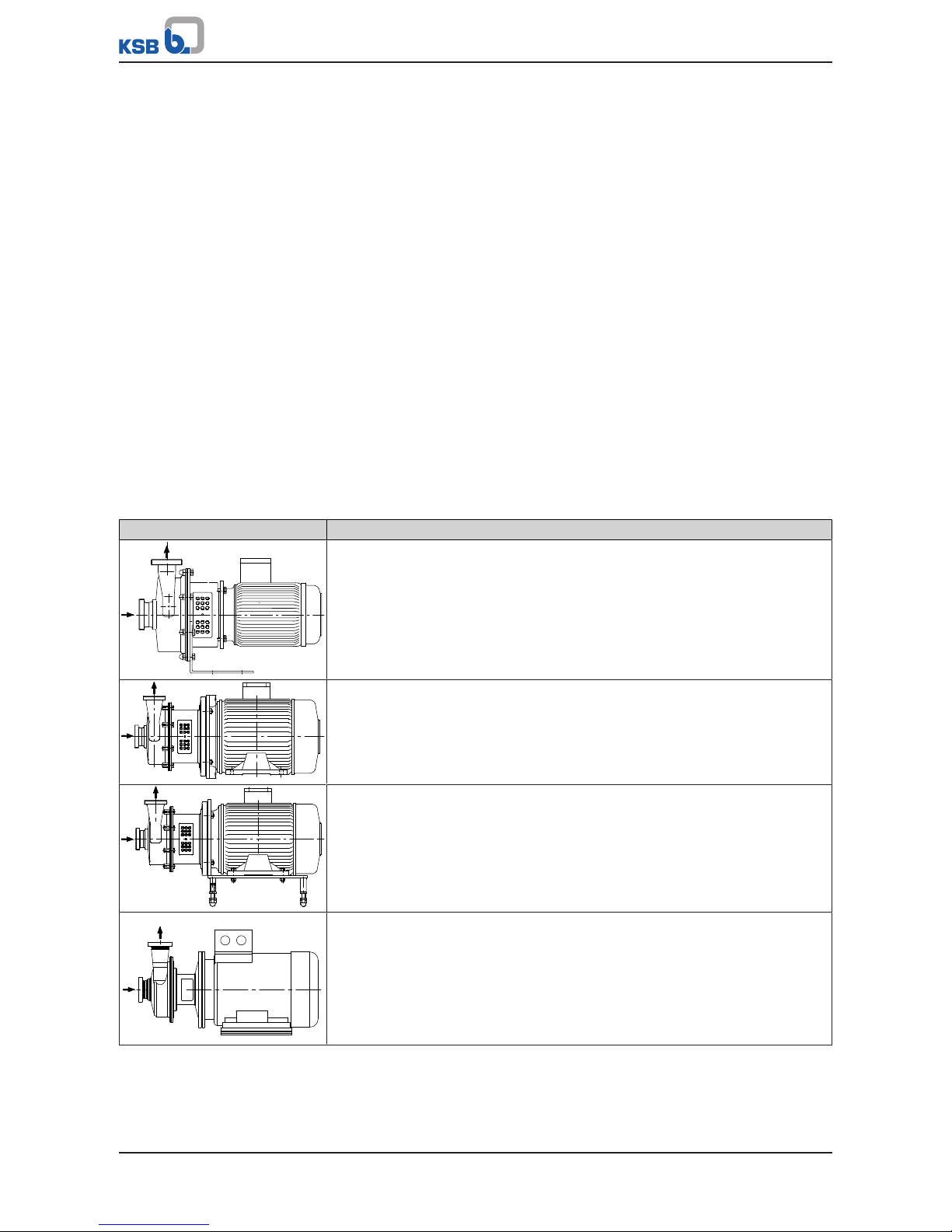
To transport the pump/pump set suspend it from the lifting tackle as shown.
1213:302/3
Fig.1: Transporting the pump
Fig.2: Transporting the pump set (with angle foot, for motors≤4kW)
Fig.3: Transporting the pump set (for motors≥5.5kW)
3.3 Storage/preservation
If commissioning is to take place some time after delivery, we recommend that the
following measures be taken for pump (set) storage.
Page 13
3 Transport/Temporary Storage/Disposal
13 of 72
Vitachrom
CAUTION
Damage during storage due to humidity, dirt or vermin
Corrosion/contamination of the pump (set)!
▷ For outdoor storage cover the pump (set) or the packaged pump (set) and
accessories with waterproof material.
CAUTION
Wet, contaminated or damaged openings and connections
Leakage or damage to the pump!
▷ Clean and cover pump openings and connections as required prior to putting
the pump into storage.
Store the pump (set) in a dry, protected room where the atmospheric humidity is as
constant as possible.
Rotate the shaft by hand once a month, e.g. via the motor fan.
If properly stored indoors, the pump set is protected for a maximum of 12 months.
New pumps/pump sets are supplied by our factory duly prepared for storage.
For storing a pump (set) which has already been operated, the shutdown measures
must be adhered to. (ðSection6.3.1,Page36)
3.4 Return to supplier
1. Drain the pump as per operating instructions. (ðSection7.3,Page42)
2. Flush and clean the pump, particularly if it has been used for handling noxious,
explosive, hot or other hazardous fluids.
3. If the pump has handled fluids whose residues could lead to corrosion damage
in the presence of atmospheric humidity or could ignite upon contact with
oxygen also neutralise the pump and blow through with anhydrous inert gas to
ensure drying.
4. Always complete and enclose a certificate of decontamination when returning
the pump.
Indicate any safety measures and decontamination measures taken.
(ðSection11,Page66)
NOTE
If required, a blank certificate of decontamination can be downloaded from the
following web site: www.ksb.com/certificate_of_decontamination
Page 14
3 Transport/Temporary Storage/Disposal
14 of 72
Vitachrom
3.5 Disposal
WARNING
Fluids handled, consumables and supplies which are hot and/or pose a health
hazard
Hazard to persons and the environment!
▷ Collect and properly dispose of flushing fluid and any fluid residues.
▷ Wear safety clothing and a protective mask if required.
▷ Observe all legal regulations on the disposal of fluids posing a health hazard.
1. Dismantle the pump (set).
Collect greases and other lubricants during dismantling.
2. Separate and sort the pump materials, e.g. by:
- Metals
- Plastics
- Electronic waste
- Greases and other lubricants
3. Dispose of materials in accordance with local regulations or in another
controlled manner.
Page 15
4 Description of the Pump (Set)
15 of 72
Vitachrom
4 Description of the Pump (Set)
4.1 General description
▪ Close-coupled pump with shaft seal
▪ Hygienic pump for handling fluids in the food and beverages industry
4.2 Designation
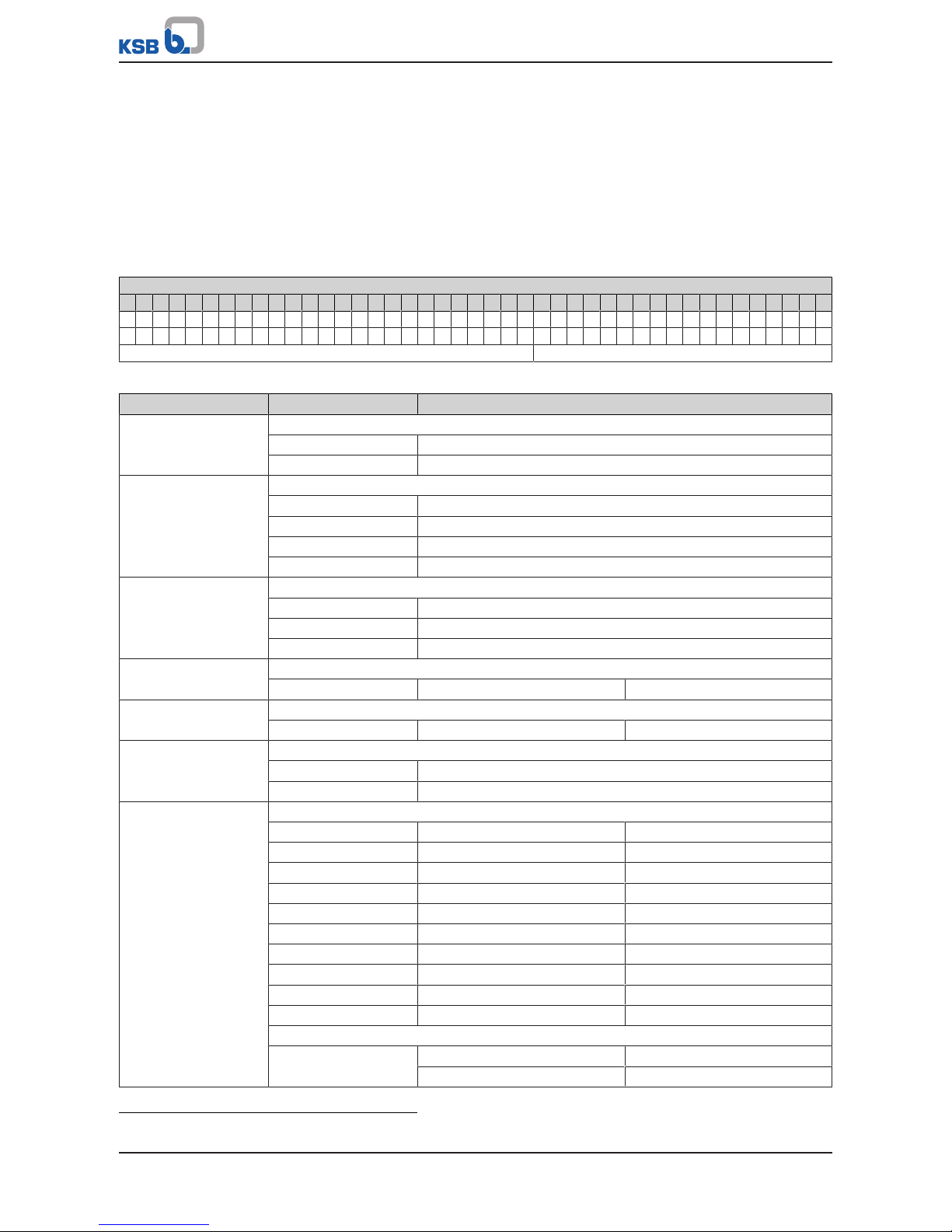
Table5: Designation example
Position
1 2 3 4 5 6 7 8 9 10 11 12 13 14 15 16 17 18 19 20 21 22 23 24 25 26 27 28 29 30 31 32 33 34 35 36 37 38 39 40 41 42 43
V C 0 5 0 - 0 5 0 - 1 2 5 C C I 0 1 M A 1 3 0 0 2 A P D 2 K S B I E 3
V C I 1 0 5 0 - 0 5 0 - 1 6 0 C C I 0 2 A B 1 1 0 0 2 e x A P D 2 E M S I E I E 4
See name plate and data sheet See data sheet
Table6: Designation key
Position Code Description
1-3 Pump type
VC Vitachrom
VCI Vitachrom Inducer
4 Inducer
2)
Without inducer
0 Inducer 0
1 Inducer 1
2 Inducer 2
5-16 Size, e.g.
050 Nominal suction nozzle diameter [mm]
050 Nominal discharge nozzle diameter [mm]
125 Nominal impeller diameter [mm]
17 Pump casing material
C Stainless steel 1.4409
18 Impeller material
C Stainless steel 1.4404
19 Design
2)
Standard
X Non-standard (BT3D, BT3)
20-22 Seal code, single mechanical seal
I01 BQ1E1-04GG Carbon/SiC/EPDM
I02 BQ1V26GG Carbon/SiC/Viton
I03 Q12Q1E1-04GG SiC/SiC/EPDM
I04 Q12Q1V26GG SiC/SiC/Viton
I06 BQ1E1-04GG Carbon/SiC/EPDM
I07 BQ1V26GG Carbon/SiC/Viton
I08 Q12Q1E1-04GG SiC/SiC/EPDM
I09 Q12Q1V26GG SiC/SiC/Viton
I10 Q22Q2E1-04GG Si-SiC/Si-SiC/EPDM
I21 Q12Q1M1GG SiC/SiC/PTFE
Seal code, double mechanical seal in tandem arrangement
T11 BQ1E1-04GG Carbon/SiC/EPDM
BQ1EGG Carbon/SiC/EPDM
2) Blank
Page 16
4 Description of the Pump (Set)
16 of 72
Vitachrom
Position Code Description
20-22 T12 BQ1V26GG Carbon/SiC/Viton
BQ1EGG Carbon/SiC/EPDM
T13 Q12Q1E1-04GG SiC/SiC/EPDM
BQ1EGG Carbon/SiC/EPDM
T14 Q12Q1V26GG SiC/SiC/Viton
BQ1EGG Carbon/SiC/EPDM
T16 BQ1E1-04GG Carbon/SiC/EPDM
BQ1EGG Carbon/SiC/EPDM
T17 BQ1V26GG Carbon/SiC/Viton
BQ1EGG Carbon/SiC/EPDM
T18 Q12Q1E1-04GG SiC/SiC/EPDM
BQ1EGG Carbon/SiC/EPDM
T19 Q12Q1V26GG SiC/SiC/Viton
BQ1EGG Carbon/SiC/EPDM
T20 Q22Q2E1-04GG Si-SiC/Si-SiC/EPDM
BQ1EGG Carbon/SiC/EPDM
T31 Q12Q1M1GG SiC/SiC/PTFE
BQ1EGG Carbon/SiC/EPDM
23 Scope of supply
A Angle foot
B Soleplate G1 / G2
K Ball feet
M Motor feet
T Round base feet
24 Pipe connection
A Flange APV FN
B Threaded connection DIN 11864-1A
C Flange DIN 11864-2A
D Clamped connection DIN 11864-3A
G Flange Varivent
G Small flange DIN
I Threaded connection ISO 2853 (IDF)
L Flange EN 1092-1
M Threaded connection DIN11851 (hygienic pipe union)
N Flange Neumo
R Flange DIN2633 (EN1092-1) with recess
S Threaded connection SMS
T Clamped connection EN 32676-A
25 O-ring material
1 EPDM
2 Viton
3 PTFE
26-28 Motor rating PN [kW]
075 7,50
... ...
100 10,00
29 Number of motor poles
30-31 Explosion protection
ex With explosion-proof motor
Page 17
4 Description of the Pump (Set)
17 of 72
Vitachrom
Position Code Description
30-31 -- Without explosion-proof motor
32 Product generation
A Vitachrom
33-36 PumpDrive
2)
Without PumpDrive
PD2 PumpDrive2
PD2E PumpDrive 2 Eco
37 PumpMeter
2)
Without PumpMeter
M PumpMeter
38-40 Motor manufacturer
KSB KSB
SIE Siemens
LOH Loher
HAL Halter
41-43 Efficiency class
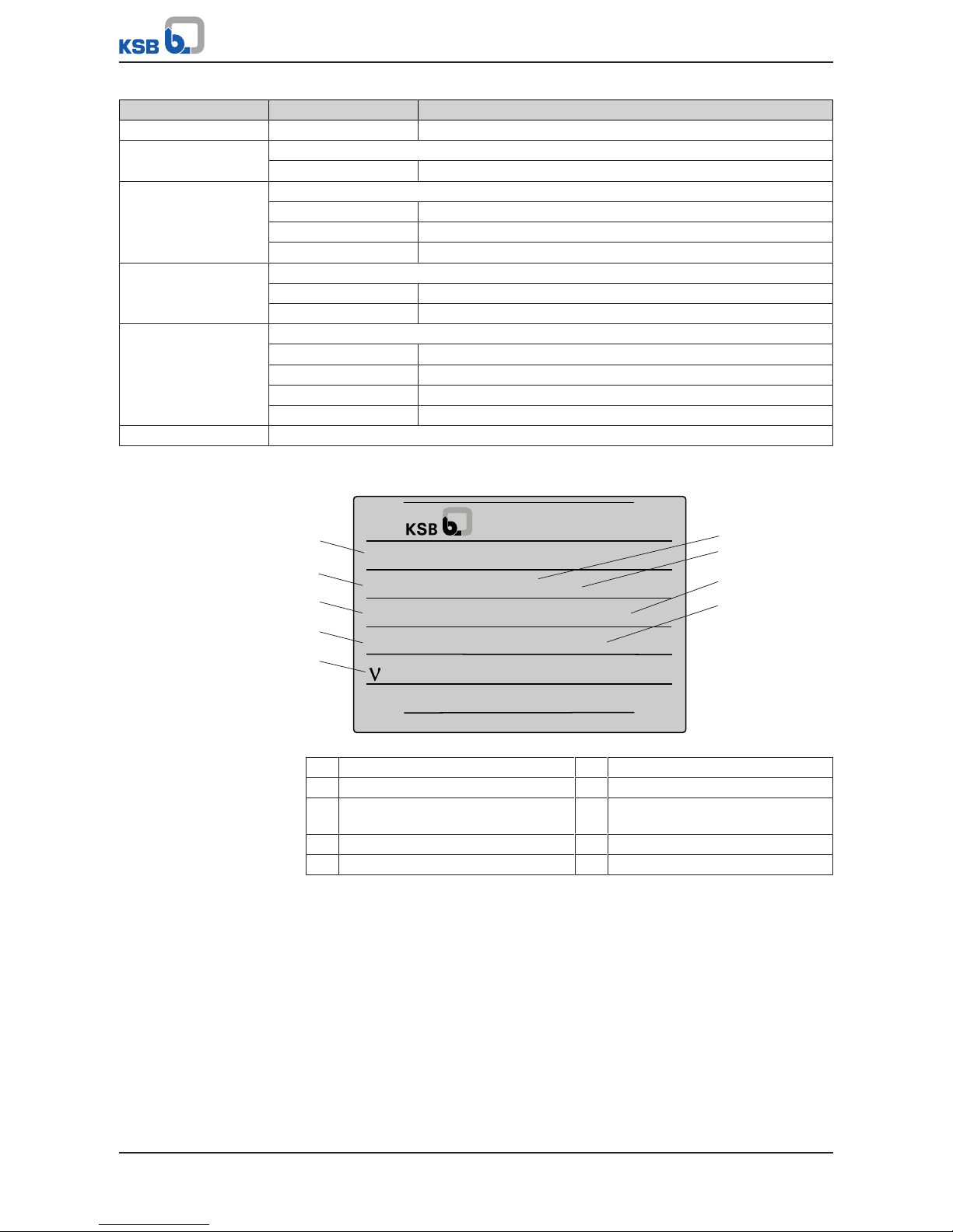
4.3 Name plate
VC 050-050-125 CC IO1MM1
9971372989 000300 02
Q 100 m3/h l H 50 m
1 mm2/s
n 2900 1/min l 2016
Id-No. 00 117 385 ZN 3804 - C 37 x 52
1
2
5
4
3
9
8
7
6
Johann-Klein-Straße 9
Deutschland
67227 Frankenthal
KSB SE & Co. KGaA
Fig.4: Name plate Vitachrom (example)
1 Type series, size and version 2 KSB order number (ten digits)
3 Flow rate 4 Speed
5 Kinematic viscosity of the fluid
handled
6 Order item number (six digits)
7 Consecutive number (two digits) 8 Head
9 Year of construction
4.4 Design details
Design
▪ Standard design with materials to Regulation (EC) No.1935/2004
▪ Design to ATEX
Design
▪ Centrifugal pump
▪ Close-coupled design
▪ Single-stage
Page 18

4 Description of the Pump (Set)
18 of 72
Vitachrom
▪ Wetted parts made of stainless steel 1.4404/1.4409 (AISI316L/CF3M)
▪ CIP/SIP-compatible
▪ Pump version with inducer for fluids pumped from vessels under vacuum (pump
sizes 65-160-IND, 80-250-IND, 80-250.1-IND only) and for low NPSH values
Pump casing
▪ Annular casing
Impeller type
▪ Semi-open multi-vane impeller
Shaft seal
▪ Single mechanical seal surrounded by fluid handled EN 12756
▪ Double mechanical seal in tandem arrangement with quench to EN 12756
▪ Hygienic design or sterile design
Hygienic design:
▪ Inboard seal with spring surrounded by fluid handled, unidirectional
Sterile design:
▪ Inboard seal with covered spring, polished surface, bi-directional
Bearings
▪ No separate pump bearings
Drive
▪ Surface-cooled KSB squirrel-cage motor
▪ Type of construction V1, V15 / B5, B35
▪ Enclosure IP55
▪ Thermal class F
▪ 3 PTC thermistors
▪ Duty cycle: continuous duty S1
▪ Winding 50Hz, 220-240V/ 380-420V≤2.20kW; 380-420V/ 660-
725V≥3.00kW
▪ 60Hz winding, 440-480V
Explosion-proof version:
▪ KSB surface-cooled IEC three-phase current squirrel-cage motor
▪ 50Hz winding, 220-240V/ 380-420V ≤1.85kW
▪ 50Hz winding, 380-420V/ 660-725V ≥2.50kW
▪ Type of construction IMV1 ≤3.30kW
▪ Type of construction IMV15 ≥4.60kW
▪ Enclosure IP55 or IP54
▪ Type of protection EEx e II
▪ Type of protection Ex de ll
▪ Temperature class T3
▪ Duty cycle: continuous duty S1
Automation
Automation options:
▪ PumpDrive
▪ PumpMeter
Page 19
4 Description of the Pump (Set)
19 of 72
Vitachrom
Connections
▪ Axial suction nozzle, tangential discharge nozzle
▪ Adjustable through 360°
Standard:
▪ Threaded connection to DIN11851 (hygienic pipe union)
▪ Flange to EN1092-1
Alternative:
▪ Flange to DIN11864-2-NF-A
▪ Flange to EN1092-1-F
▪ Flange to APV-FN
▪ Threaded connection to DIN11864-1-GS-A
▪ Threaded connection to IDF (ISO2853)
▪ Threaded connection to SMS standard
▪ Clamped connection to DIN32676-A
▪ Clamped connection to ISO2852
▪ Other connection types on request
4.5 Mounting arrangements
Table7: Mounting arrangements for horizontal installation
Mounting arrangement Description
1966.6
Pump set angle foot mounted
▪ Motor frame size 90 to 112
Pump set motor foot mounted
▪ Motor frame size 90 to 280
Pump set ball feet mounted
▪ Motor frame size 90 to 280
▪ Alternatively mounted on rubber-padded round base feet
Pump set soleplate mounted
▪ Motor frame size 90 to 280
Page 20
4 Description of the Pump (Set)
20 of 72
Vitachrom
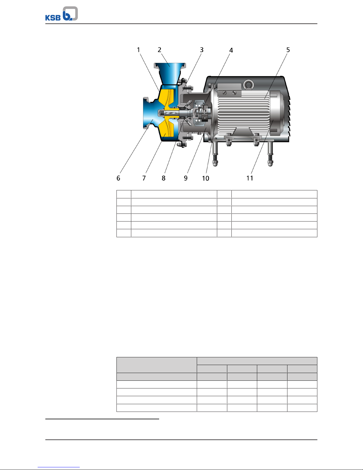
4.6 Configuration and function
Fig.5: Vitachrom sectional drawing
1 Clearance gap 2 Discharge nozzle
3 Discharge cover 4 Shaft
5 Motor housing 6 Suction nozzle
7 Impeller 8 Shaft seal
9 Drive lantern 10 Rolling element bearing
11 Rolling element bearing
Design The pump is designed with an axial fluid inlet and a radial outlet. The hydraulic
system is rigidly connected to the motor via a stub shaft.
Function The fluid enters the pump via a suction nozzle (6) and is accelerated outward in a
radial flow by the rotating impeller (7). The flow profile of the pump casing converts
the kinetic energy of the fluid into pressure energy. The fluid is pumped to the
discharge nozzle (2), where it leaves the pump. The clearance gap (1) prevents any
fluid from flowing back from the casing into the inlet. The hydraulic system is closed
with a casing cover (3) at the rear side of the impeller; the shaft (4) enters the casing
via the casing cover (3). The shaft passage through the casing cover is sealed to
atmosphere with a dynamic shaft seal (8). The shaft runs in rolling element bearings
(10 and 11), which are supported by a motor housing (5) linked with the pump casing
and/or casing cover via a drive lantern.
Sealing The pump is sealed by a standardised mechanical seal (option: two mechanical seals
in tandem arrangement).
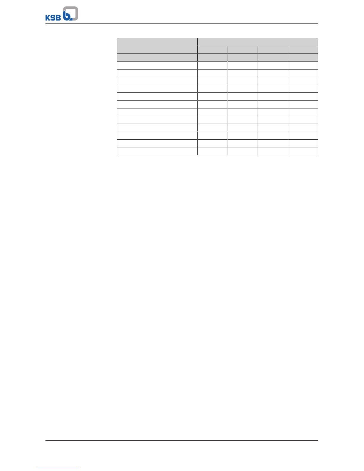
4.7 Noise characteristics
Table8: Surface sound pressure level L
pA
3)
Rated power input
P
N
Pump set
1450 rpm-11750 rpm-12900 rpm-13500 rpm
-1
[kW] [dB] [dB] [dB] [dB]
1,5 60 61 67 70
2,2 62 63 69 72
3 64 65 70 73
4 66 67 72 75
3) Spatial average; as per ISO 3744 and EN 12639; valid for pump operation in the Q/Qopt = 0.8 - 1.1 range and for noncavitating operation. If noise levels are to be guaranteed, add +3dB for measuring and constructional tolerance.
Page 21
4 Description of the Pump (Set)
21 of 72
Vitachrom
Rated power input
P
N
Pump set
1450 rpm-11750 rpm-12900 rpm-13500 rpm
-1
[kW] [dB] [dB] [dB] [dB]
5,5 68 69 74 77
7,5 70 71 76 79
11 73 74 78 81
15 75 76 80 83
18,5 76 77 82 85
22 80 81 84 87
30 81 82 86 89
37 - - 88 91
45 - - 90 93
55 - - 92 95
75 - - 95 98
90 - - 97 100
4.8 Scope of supply
Depending on the model, the following items are included in the scope of supply:
▪ Pump
▪ Drive
Accessories
E.g.:
▪ Pump foot or vertically adjustable ball feet.
▪ Motor shroud (only in combination with vertically adjustable ball feet)
▪ Mechanical seal in tandem arrangement (quench arrangement)
4.9 Dimensions and weights
For dimensions and weights please refer to the general arrangement drawing/outline
drawing of the pump/pump set.
Page 22
5 Installation at Site
22 of 72
Vitachrom
5 Installation at Site
5.1 Checks to be carried out prior to installation
Place of installation
WARNING
Installation on mounting surface which is unsecured and cannot support the load
Personal injury and damage to property!
▷ Use a concrete of compressive strength class C12/15 which meets the
requirements of exposure class XC1 to EN206-1.
▷ The mounting surface must be set, flat, and level.
▷ Observe the weights indicated.
1. Check the structural requirements.
All structural work required must have been prepared in accordance with the
dimensions stated in the outline drawing/general arrangement drawing.
5.2 Installing the pump set
DANGER
Static charging due to insufficient potential equalisation
Explosion hazard!
▷ Make sure that the connection between pump and baseplate is electrically
conductive.
CAUTION
Ingress of leakage into the motor
Damage to the pump!
▷ Never install the pump set with the "motor below".
Fastening Table9: Types of fastening
Motor size Type of fastening
Up to 112 M Angle foot
All motor sizes Motor feet
All motor sizes Ball feet
NOTE
For installation on motor feet of motor sizes 132 or 160, the motor feet must be
shimmed (20mm shim height).
5.2.1 Removing the transport lock
Removing the transport lock
Removing the foam insert ü Delivery of pump without motor
1. Suspend or support the back pull-out unit to prevent it from tipping over.
2. Undo hexagon nut 920.02 and hexagon head bolt 901.02 at pump casing 103.
3. Remove discharge cover 163 and set it aside.
4. Pull the back pull-out unit out of the pump casing and place it on a clean, level
surface.
5. Remove the foam insert from the pump casing.
Page 23

5 Installation at Site
23 of 72
Vitachrom
6. Push the back pull-out unit into the pump casing.
7. Fit the discharge cover.
8. Tighten hexagon nut 920.02 and hexagon head bolt 901.02 at the pump casing.
Tightening torque (ðSection7.6.1,Page50)
Loosening the locking
bolts
4)
1. Loosen the two locking bolts in drive lantern 341 by at least 4 turns and lock
with the two hexagon nuts.
ð The locking bolts must no longer touch shaft 210.
2. Mount the motor. (ðSection5.2.1.1,Page23)
Loosening the lock
washers
5)
1. Loosen both lock washers 931 on the outside of the discharge cover, pull
outward and secure with the two screws/bolts.
ð The lock washers must no longer touch shaft 210.
2. Mount the motor. (ðSection5.2.1.1,Page23)
5.2.1.1 Mounting the motor
DANGER
Incorrect shaft connection
Explosion hazard!
▷ Connect the shafts between pump and motor as described in this manual.
12
3
456
Fig.6: Fitting the motor shaft stub on the shaft
1 Shaft slot 2 Keyway of the motor shaft
3 Slot of the locking ring 4 Locking ring
5 Motor shaft 6 Shaft
ü The notes and steps stated in (ðSection7.5.1,Page45) have been observed/
carried out.
1. The motor has been installed and fastened if required.
(ðSection7.5.4,Page48)
2. Fasten drive latern 341 on the motor.
3. Mount support foot 183, depending on the size.
4. Slip shaft 210 and locking ring 515 on motor shaft.
5. Adjust axial clearance between impeller and pump casing.
(ðSection7.5.5,Page49)
6. Make sure that the slot of shaft 210 aligns with the slot of locking ring 515, and
that they are located opposite the keyway of the motor shaft. (See illustration:
Fitting the motor shaft stub on shaft 210)
7. Fasten the shaft to the motor shaft using the locking ring.
4) Applies to Vitachrom 50-50-125/160/200, 65-65-125/160/200 and 80-80-125/160
5) Applies to Vitachrom 50-50-250, 65-65-250, 80-80-250, 100-100-200 and 125-125-200
Page 24

5 Installation at Site
24 of 72
Vitachrom
5.2.2 Installing the pump set
ü Delivery of a pump set
1. Position the pump set on the foundation and fasten it. (ðSection5.2,Page22)
2. Place a spirit level on the discharge nozzle to align the pump set.
5.3 Piping
5.3.1 Connecting the piping
DANGER
Impermissible loads acting on the pump nozzles
Danger to life from escaping hot, toxic, corrosive or flammable fluids!
▷ Do not use the pump as an anchorage point for the piping.
▷ Anchor the pipes in close proximity to the pump and connect them properly
without transmitting any stresses or strains.
▷ Observe the permissible forces and moments at the pump nozzles.
▷ Take appropriate measures to compensate for thermal expansion of the piping.
CAUTION
Incorrect earthing during welding work at the piping
Destruction of rolling element bearings (pitting effect)!
▷ Never earth the electric welding equipment on the pump or baseplate.
▷ Prevent current flowing through the rolling element bearings.
NOTE
Installing check and shut-off elements in the system is recommended, depending on
the type of plant and pump. However, such elements must not obstruct proper
drainage or hinder disassembly of the pump.
ü Suction lift lines have been laid with a rising slope, the suction head line with a
downward slope towards the pump.
ü A flow stabilisation section having a length equivalent to at least twice the
diameter of the suction flange has been provided upstream of the suction flange.
ü The nominal diameters of the pipelines are equal to or greater than the nominal
diameters of the pump nozzles.
ü Adapters to larger nominal diameters are designed with a diffuser angle of
approx. 8° to avoid excessive pressure losses.
ü The pipelines have been anchored in close proximity to the pump and connected
without transmitting any stresses or strains.
1. Thoroughly clean, flush and blow through all vessels, pipelines and connections
(especially of new installations).
2. Before installing the pump in the piping, remove the flange covers on the
suction and discharge nozzles of the pump.
CAUTION
Welding beads, scale and other impurities in the piping
Damage to the pump!
▷ Remove any impurities from the piping.
▷ If necessary, install a filter.
▷ Observe the information in (ðSection7.2.2.2,Page41) .
Page 25

5 Installation at Site
25 of 72
Vitachrom
3. If required, install a filter in the piping (see drawing: Filter in the piping).
1
2
Fig.7: Filter in the piping
1 Differential pressure gauge 2 Filter
NOTE
Use a filter with laid-in wire mesh (mesh width 0.5mm, wire diameter 0.25mm) of
corrosion-resistant material.
Use a filter with a filter area three times the cross-section of the piping.
Conical filters have proved suitable.
4. Connect the pump nozzles to the piping.
CAUTION
Aggressive flushing liquid and pickling agent
Damage to the pump!
▷ Match the cleaning operation mode and duration of flushing and pickling to
the casing materials and seal materials used.
5.3.2 Permissible forces and moments at the pump nozzles
No piping-induced forces and moments (from warped pipelines or thermal
expansion, for example) must act on the pump.
The discharge and suction-side pipes must be anchored in such a way that no forces
and moments may act on the discharge and suction nozzle of the pump casing.
Otherwise, there is a risk of the impeller rubbing against the pump casing on the
suction-side, due to the narrow clearance between the impeller and the suction-side
floor of the pump casing.
5.3.3 Vacuum balance line
NOTE
Where fluid has to be pumped out of a vessel under vacuum, installing a vacuum
balance line is recommended.
The following rules apply to vacuum balance lines:
▪ Minimum nominal line diameter 25 mm.
▪ The line extends above the highest permissible fluid level in the vessel.
Page 26

5 Installation at Site
26 of 72
Vitachrom
1 2
5
43
6
Fig.8: Vacuum balance system
1 Vessel under vacuum 2 Vacuum balance line
3 Shut-off element 4 Swing check valve
5 Main shut-off element 6 Vacuum-tight shut-off element
NOTE
An additional line fitted with a shut-off valve (from the pump discharge nozzle to
the balance line) facilitates venting of the pump before start-up.
5.3.4 Auxiliary connections
DANGER
Risk of potentially explosive atmosphere by mixing of incompatible fluids in the
auxiliary piping
Risk of burns!
Explosion hazard!
▷ Make sure that the barrier fluid or quench liquid are compatible with the fluid
handled.
CAUTION
Failure to use or incorrect use of auxiliary connections (quench liquid)
Malfunction of the pump!
▷ Refer to the general arrangement drawing, the piping layout and pump
markings (if any) for the number, dimensions and locations of auxiliary
connections.
▷ Use the auxiliary connections provided.
If a shaft seal with quench is used, fit the quench reservoir in the immediate vicinity
of the pump set approximately 1 metre above the pump centreline. Fluid circulation
is ensured by thermosyphon effect or forced circulation.
Suitable fittings are available as accessories. When mounting the fittings comply with
the instructions provided by the fitting manufacturers.
Quench fluid supply
Connections ▪ Pipe to DIN 2391
▪ Compression-type fitting to DIN 2353
Page 27

5 Installation at Site
27 of 72
Vitachrom
Suitable fittings are available as accessories. When mounting the fittings comply with
the instructions provided by the fitting manufacturers.
NOTE
The flushing liquid feed line must be laid with a continuously rising slope towards
the flushing liquid reservoir.
Arrangement Fit the quench reservoir (available as accessory) in the immediate vicinity of the pump
set approximately one metre above the pump centreline.
Fluid circulation is ensured by thermosyphon effect or forced circulation.
5.4 Enclosure/insulation
DANGER
Risk of potentially explosive atmosphere due to insufficient venting
Explosion hazard!
▷ Make sure the space between the casing cover/discharge cover and the bearing
cover is sufficiently vented.
▷ Never close or cover the perforation of the bearing bracket guards (e.g. by
insulation).
WARNING
The volute casing and casing/discharge cover take on the same temperature as the
fluid handled
Risk of burns!
▷ Insulate the volute casing.
▷ Fit protective equipment.
CAUTION
Heat build-up in the bearing bracket
Damage to the bearing!
▷ Never insulate the bearing bracket, bearing bracket lantern and casing cover.
5.5 Electrical connection
DANGER
Electrical connection work by unqualified personnel
Risk of fatal injury due to electric shock!
▷ Always have the electrical connections installed by a trained and qualified
electrician.
▷ Observe regulations IEC 60364 and, for explosion-proof models, EN60079.
WARNING
Incorrect connection to the mains
Damage to the mains network, short circuit!
▷ Observe the technical specifications of the local energy supply companies.
1. Check the available mains voltage against the data on the motor name plate.
2. Select an appropriate starting method.
Page 28

5 Installation at Site
28 of 72
Vitachrom
NOTE
A motor protection device is recommended.
5.5.1 Setting the time relay
CAUTION
Switchover between star and delta on three-phase motors with star-delta starting
takes too long.
Damage to the pump (set)!
▷ Keep switch-over intervals between star and delta as short as possible.
Table10: Time relay settings for star-delta starting:
Motor rating Y time to be set
[kW] [s]
≤ 30 < 3
> 30 < 5
5.5.2 Connecting the motor
NOTE
In compliance with IEC 60034-8, three-phase motors are always wired for clockwise
rotation (looking at the motor shaft stub).
The pump's direction of rotation is indicated by an arrow on the pump.
1. Match the motor's direction of rotation to that of the pump.
2. Observe the manufacturer's product literature supplied with the motor.
5.5.3 Earthing
DANGER
Electrostatic charging
Explosion hazard!
Damage to the pump set!
▷ Connect the PE conductor to the earthing terminal provided.
▷ Provide for potential equalisation between the pump set and foundation.
5.6 Checking the direction of rotation
WARNING
Hands inside the pump casing
Risk of injuries, damage to the pump!
▷ Always disconnect the pump set from the power supply and secure it against
unintentional start-up before inserting your hands or other objects into the
pump.
Page 29

5 Installation at Site
29 of 72
Vitachrom
CAUTION
Incorrect direction of rotation with non-reversible mechanical seal
Damage to the mechanical seal and leakage!
▷ Separate the pump from the motor to check the direction of rotation.
CAUTION
Drive and pump running in the wrong direction of rotation
Damage to the pump!
▷ Refer to the arrow indicating the direction of rotation on the pump.
▷ Check the direction of rotation. If required, check the electrical connection and
correct the direction of rotation.
The correct direction of rotation of motor and pump is clockwise (seen from the drive
end).
1. Start the motor and stop it again immediately to determine the motor's
direction of rotation.
2. Check the direction of rotation.
The motor's direction of rotation must match the arrow indicating the direction
of rotation on the pump.
3. If the motor is running in the wrong direction of rotation, check the electrical
connection of the motor and the control system if applicable.
Page 30

6 Commissioning/Start-up/Shutdown
30 of 72
Vitachrom
6 Commissioning/Start-up/Shutdown
6.1 Commissioning/Start-up
6.1.1 Prerequisites for commissioning/start-up
Before commissioning/starting up the pump set, make sure that the following
conditions are met:
▪ The pump set has been properly connected to the power supply and is equipped
with all protection devices. (ðSection5.5,Page27)
▪ The pump has been primed with the fluid to be handled. The pump has been
vented. (ðSection6.1.2,Page30)
▪ The direction of rotation has been checked.
▪ All auxiliary connections required are connected and operational.
▪ The lubricants have been checked.
▪ After prolonged shutdown of the pump (set), the activities required for returning
the equipment to service have been carried out. (ðSection6.4,Page37)
▪ The lock washers, if any, have been removed from the shaft groove.
6.1.2 Priming and venting the pump
DANGER
Risk of potentially explosive atmosphere by mixing of incompatible fluids in the
auxiliary piping
Risk of burns!
Explosion hazard!
▷ Make sure that the barrier fluid or quench liquid are compatible with the fluid
handled.
DANGER
Risk of potentially explosive atmosphere inside the pump
Explosion hazard!
▷ The pump internals in contact with the fluid to be handled, including the seal
chamber and auxiliary systems must be filled with the fluid to be handled at all
times.
▷ Provide sufficient inlet pressure.
▷ Provide an appropriate monitoring system.
CAUTION
Increased wear due to dry running
Damage to the pump set!
▷ Never operate the pump set without liquid fill.
▷ Never close the shut-off element in the suction line and/or supply line during
pump operation.
1. Vent the pump and suction line and prime both with the fluid to be handled.
2. Fully open the shut-off element in the suction line.
3. Fully open all auxiliary feed lines (barrier fluid, flushing liquid, etc.), if any.
Page 31

6 Commissioning/Start-up/Shutdown
31 of 72
Vitachrom
NOTE
For design-inherent reasons some unfilled volume in the hydraulic system cannot be
excluded after the pump has been primed for commissioning/start-up. However,
once the motor is started up the pumping effect will immediately fill this volume
with the fluid handled.
6.1.3 Start-up
DANGER
Non-compliance with the permissible pressure and temperature limits if the pump
is operated with the suction and/or discharge line closed.
Explosion hazard!
Hot or toxic fluids escaping!
▷ Never operate the pump with the shut-off elements in the suction line and/or
discharge line closed.
▷ Only start up the pump set with the discharge-side shut-off element slightly or
fully open.
DANGER
Excessive temperatures due to dry running or excessive gas content in the fluid
handled
Explosion hazard!
Damage to the pump set!
▷ Never operate the pump set without liquid fill.
▷ Prime the pump as per operating instructions.
▷ Always operate the pump within the permissible operating range.
CAUTION
Abnormal noises, vibrations, temperatures or leakage
Damage to the pump!
▷ Switch off the pump (set) immediately.
▷ Eliminate the causes before returning the pump set to service.
ü The system piping has been cleaned.
ü The pump, suction line and inlet tank, if any, have been vented and primed with
the fluid to be pumped.
ü The lines for priming and venting have been closed.
CAUTION
Start-up against open discharge line
Motor overload!
▷ Make sure the motor has sufficient power reserves.
▷ Use a soft starter.
▷ Use speed control.
1. Fully open the shut-off element in the suction head/suction lift line.
2. Close or slightly open the shut-off element in the discharge line.
Page 32

6 Commissioning/Start-up/Shutdown
32 of 72
Vitachrom
3. Start up the motor.
4. Immediately after the pump has reached full rotational speed, slowly open the
shut-off element in the discharge line and adjust it to comply with the duty
point.
6.1.4 Checking the shaft seal
Mechanical seal The mechanical seal only leaks slightly or invisibly (as vapour) during operation.
Mechanical seals are maintenance-free.
6.1.5 Shutdown
CAUTION
Heat build-up inside the pump
Damage to the shaft seal!
▷ Depending on the type of installation, the pump set requires sufficient after-
run time – with the heat source switched off – until the fluid handled has
cooled down.
CAUTION
Backflow of fluid handled is not permitted
Motor or winding damage! Mechanical seal damage!
▷ Close the shut-off elements.
ü The shut-off element in the suction line is and remains open.
1. Close the shut-off element in the discharge line.
2. Switch off the motor and make sure the pump set runs down smoothly to a
standstill.
NOTE
If the discharge line is equipped with a non-return or check valve, the shut-off
element may remain open provided that the system conditions and system
regulations are considered and observed.
For prolonged shutdown periods:
1. Close the shut-off element in the suction line.
2. Close any auxiliary lines.
If the fluid to be handled is fed in under vacuum, also supply the shaft seal with
barrier fluid during standstill.
CAUTION
Risk of freezing during prolonged pump shutdown periods
Damage to the pump!
▷ Drain the pump and the cooling/heating chambers (if any) or otherwise protect
them against freezing.
6.1.6 Quench liquid supply
Permissible quench liquids The quench liquid should preferably form a solution with the fluid handled and be
environmentally compatible.
Page 33

6 Commissioning/Start-up/Shutdown
33 of 72
Vitachrom
Typical quench liquids:
▪ Water with a conductivity of 100-800 µS/cm
▪ Water/glycol mixtures
▪ Glycerine
6)
Temperature and pressure
limits
Table11: Permissible temperature and pressure limits
Minimum Maximum
Temperature -10°C
and
T
Melting
+10 °C
7)
60 °C
and
T
Boiling
-10 °C
7)
Pressure Ambient pressure 0.5 bar gauge pressure
One-way quench The one-way quench supply should be adjusted to a constant flow ≥ 0.3 l/min.
6.2 Operating limits
DANGER
Non-compliance with operating limits for pressure, temperature, fluid handled and
speed
Explosion hazard!
Hot or toxic fluid could escape!
▷ Comply with the operating data indicated in the data sheet.
▷ Never use the pump for handling fluids it is not designed for.
▷ Avoid prolonged operation against a closed shut-off element.
▷ Never operate the pump at temperatures, pressures or rotational speeds
exceeding those specified in the data sheet or on the name plate unless the
written consent of the manufacturer has been obtained.
DANGER
Formation of a potentially explosive atmosphere inside the pump
Explosion hazard!
▷ When draining tanks take suitable measures to prevent dry running of the
pump (e.g. fill level monitoring).
6.2.1 Ambient temperature
CAUTION
Operation outside the permissible ambient temperature
Damage to the pump (set)!
▷ Observe the specified limits for permissible ambient temperatures.
Observe the following parameters and values during operation:
Table12: Permissible ambient temperatures
Permissible ambient temperature Value
Maximum 40 °C
Minimum See data sheet.
6) Make sure the circulation line diameter is ≥ ¼".
7) Depending on quench liquid used.
Page 34

6 Commissioning/Start-up/Shutdown
34 of 72
Vitachrom
6.2.2 Frequency of starts
DANGER
Excessive surface temperature of the motor
Explosion hazard!
Damage to the motor!
▷ In case of explosion-proof motors, observe the frequency of starts specified in
the manufacturer's product literature.
The frequency of starts is usually determined by the maximum temperature increase
of the motor. This largely depends on the power reserves of the motor in steadystate operation and on the starting conditions (DOL, star-delta, moments of inertia,
etc). If the starts are evenly spaced over the period indicated, the pump set can be
started up six times per hour (h) with the discharge-side gate valve slightly open.
CAUTION
Re-starting while motor is still running down
Damage to the pump (set)!
▷ Do not re-start the pump set before the pump rotor has come to a standstill.
6.2.3 Cleaning in place (CIP)
CAUTION
Elastomers do not have sufficient resistance
Damage to the pump!
▷ Effect cleaning/sterilisation only if the elastomer components used in the pump
(e.g. O-rings, mechanical seals) are made of EPDM or other approved materials.
Application CIP may be effected with the pump running or with the pump stopped.
Cleaning agents When CIP cleaning a system where the pump set is installed, make sure to comply
with the concentration limits, temperature limits and contact times given below for
the cleaning agents and disinfectants:
Table13: Cleaning agents for CIP
Cleaning agents Concentration
(% b.w.)
Temperature t
[°C]
Contact time
[h]
Sodium hydroxide
(soda lye)
5 90 -
Phosphoric acid 3 90 ≤ 1
Hot water - 90 Lye (alkaline) 5 90 Nitric acid 2 50 ≤ 0.5
Peracetic acid or
hydrogen peroxide
0.5
1
40
20
≤ 0.5
6.2.4 SIP (steaming in place)
WARNING
Pump casing takes on the same temperature as the sterilisation fluid
Risk of burns!
▷ Fit additional protective devices.
▷ Observe the general safety rules and regulations for steam applications.
Page 35

6 Commissioning/Start-up/Shutdown
35 of 72
Vitachrom
CAUTION
Elastomers do not have sufficient resistance
Damage to the pump!
▷ Effect cleaning/sterilisation only if the elastomer components used in the pump
(e.g. O-rings, mechanical seals) are made of EPDM or other approved materials.
CAUTION
SIP with the pump running
Damage to the mechanical seals!
▷ Effect SIP (cleaning using superheated steam) only during standstill of the
pump set.
Conditions Only effect SIP during standstill of the pump set.
Limits Table14: SIP temperature requirements
Parameter Value
Maximum temperature of saturated
steam (SIP)
140 °C
Absolute pressure 3 bar
6.2.5 Fluid handled
6.2.5.1 Flow rate
Table15: Flow rate
Temperature range (t) Minimum flow rate Maximum flow rate
-30 to +70 ℃ ≈ 15 % of Q
Opt
8)
See hydraulic curves
> 70 to +110 °C ≈ 25 % of Q
Opt
8)
The calculation formula below can be used to check if an additional heat build-up
could lead to a dangerous temperature increase at the pump surface.
×
×
×
Table16: Key
Symbol Description Unit
c Specific heat capacity J/kg K
g Gravitational constant m/s²
H Pump discharge head m
T
f
Fluid temperature °C
T
O
Temperature at the casing surface °C
Pump efficiency at duty point Temperature difference K
6.2.5.2 Density of the fluid handled
The pump input power changes in proportion to the density of the fluid handled.
8) Best efficiency point
Page 36

6 Commissioning/Start-up/Shutdown
36 of 72
Vitachrom
CAUTION
Impermissibly high density of the fluid handled
Motor overload!
▷ Observe the information about fluid density in the data sheet.
▷ Make sure the motor has sufficient power reserves.
6.2.5.3 Viscosity of the fluid handled
The discharge head, flow rate and power input of the pump are influenced by the
viscosity of the fluid handled.
CAUTION
The fluid handled has a higher viscosity than permitted.
Risk of motor overload!
▷ Observe the viscosity limits for the fluid handled given in the data sheet.
▷ Make sure the motor has sufficient power reserves.
6.2.5.4 Abrasive fluids
The fluid handled may contain abrasive particles up to a maximum content of 5g/
dm³ and a maximum particle size of 0.5mm. When the pump handles fluids
containing abrasive substances, increased wear of the hydraulic system and the shaft
seal are to be expected. In this case, reduce the commonly recommended inspection
intervals.
DANGER
Abraded casing wall
Explosion hazard!
▷ Use a pump with anti-swirl baffle.
▷ Adjust the inspection intervals to the increased abrasion.
▷ For combustible fluids: The fluids must not contain any abrasive particles.
6.3 Shutdown/storage/preservation
6.3.1 Measures to be taken for shutdown
The pump (set) remains installed
ü Sufficient fluid is supplied for the operation check run of the pump.
1. For prolonged shutdown periods, start up the pump (set) regularly between
once a month and once every three months for approximately five minutes.
ð This will prevent the formation of deposits within the pump and the pump
intake area.
Page 37

6 Commissioning/Start-up/Shutdown
37 of 72
Vitachrom
The pump (set) is removed from the pipe and stored
ü The pump has been properly drained.
ü The safety instructions for dismantling the pump have been observed.
(ðSection7.4.1,Page42)
1. Spray-coat the inside wall of the pump casing and, in particular, the impeller
clearance areas with a preservative.
2. Spray the preservative through the suction nozzle and discharge nozzle.
It is advisable to then close the pump nozzles (e.g. with plastic caps).
3. Oil or grease all exposed machined parts and surfaces of the pump (with
silicone-free oil or grease, food-approved if required) to protect them against
corrosion.
Observe the additional instructions on preservation. (ðSection3.3,Page12)
If the pump set is to be stored temporarily, only preserve the wetted components
made of low-alloy materials. Commercially available preservatives (food-approved, if
required) can be used for this purpose. Observe the manufacturer's instructions for
application/removal.
Observe any additional instructions and information provided. (ðSection3,Page12)
6.4 Returning to service
For returning the equipment to service observe the sections on commissioning/startup and the operating limits. (ðSection6.1,Page30) (ðSection6.2,Page33)
In addition, carry out all servicing/maintenance operations before returning the
pump (set) to service. (ðSection7,Page38)
WARNING
Failure to re-install or re-activate protective devices
Risk of injury from moving parts or escaping fluid!
▷ As soon as the work is completed, re-install and re-activate any safety-relevant
devices and protective devices.
NOTE
If the pump has been out of service for more than one year, replace all elastomer
seals.
Page 38

7 Servicing/Maintenance
38 of 72
Vitachrom
7 Servicing/Maintenance
7.1 Safety regulations
DANGER
Sparks produced during servicing work
Explosion hazard!
▷ Observe the safety regulations in force at the place of installation!
▷ Always perform maintenance work on explosion-proof pump sets outside
potentially explosive atmospheres.
DANGER
Improperly serviced pump set
Explosion hazard!
Damage to the pump set!
▷ Service the pump set regularly.
▷ Prepare a maintenance schedule with special emphasis on lubricants and shaft
seal.
The operator ensures that maintenance, inspection and installation is performed by
authorised, qualified specialist personnel who are thoroughly familiar with the
manual.
WARNING
Unintentional starting of the pump set
Risk of injury by moving components and shock currents!
▷ Ensure that the pump set cannot be started unintentionally.
▷ Always make sure the electrical connections are disconnected before carrying
out work on the pump set.
DANGER
Improper cleaning of coated pump surfaces
Explosion hazard by electrostatic discharge!
▷ When cleaning coated pump surfaces in atmospheres of Explosion groupIIC,
use suitable anti-static equipment.
WARNING
Fluids handled, consumables and supplies which are hot and/or pose a health
hazard
Risk of injury!
▷ Observe all relevant laws.
▷ When draining the fluid take appropriate measures to protect persons and the
environment.
▷ Decontaminate pumps which handle fluids posing a health hazard.
Page 39

7 Servicing/Maintenance
39 of 72
Vitachrom
WARNING
Insufficient stability
Risk of crushing hands and feet!
▷ During assembly/dismantling, secure the pump (set)/pump parts to prevent
tilting or tipping over.
A regular maintenance schedule will help avoid expensive repairs and contribute to
trouble-free, reliable operation of the pump, pump set and pump parts with a
minimum of servicing/maintenance expenditure and work.
NOTE
All maintenance work, service work and installation work can be carried out by KSB
Service or authorised workshops. For contact details please refer to the enclosed
"Addresses" booklet or visit "www.ksb.com/contact" on the Internet.
Never use force when dismantling and reassembling the pump set.
7.2 Servicing/Inspection
7.2.1 Supervision of operation
DANGER
Risk of potentially explosive atmosphere inside the pump
Explosion hazard!
▷ The pump internals in contact with the fluid to be handled, including the seal
chamber and auxiliary systems must be filled with the fluid to be handled at all
times.
▷ Provide sufficient inlet pressure.
▷ Provide an appropriate monitoring system.
DANGER
Incorrectly serviced shaft seal
Explosion hazard!
Hot, toxic fluid escaping!
Damage to the pump set!
Risk of burns!
Fire hazard!
▷ Regularly service the shaft seal.
DANGER
Excessive temperatures as a result of bearings running hot or defective bearing
seals
Explosion hazard!
Fire hazard!
Damage to the pump set!
▷ Regularly check the rolling element bearings for running noises.
Page 40

7 Servicing/Maintenance
40 of 72
Vitachrom
CAUTION
Increased wear due to dry running
Damage to the pump set!
▷ Never operate the pump set without liquid fill.
▷ Never close the shut-off element in the suction line and/or supply line during
pump operation.
CAUTION
Impermissibly high temperature of fluid handled
Damage to the pump!
▷ Prolonged operation against a closed shut-off element is not permitted
(heating up of the fluid).
▷ Observe the temperature limits in the data sheet and in the section on
operating limits. (ðSection6.2,Page33)
While the pump is in operation, observe and check the following:
▪ The pump must run quietly and free from vibrations at all times.
▪ Check the shaft seal. (ðSection6.1.4,Page32)
▪ Check the static sealing elements for leakage.
▪ Check the rolling element bearings for running noises.
Vibrations, noise and an increase in current input occurring during unchanged
operating conditions indicate wear.
▪ Monitor the correct functioning of any auxiliary connections.
▪ Monitor the stand-by pump.
To make sure that stand-by pumps are ready for operation, start them up once a
week.
▪ Monitor the bearing temperature.
The bearing temperature must not exceed 90 °C (measured on the motor
housing).
CAUTION
Operation outside the permissible bearing temperature
Damage to the pump!
▷ The bearing temperature of the pump (set) must never exceed 90 °C (measured
on the outside of the motor housing).
NOTE
After commissioning, increased temperatures may occur at grease-lubricated rolling
element bearings due to the running-in process. The final bearing temperature is
only reached after a certain period of operation (up to 48 hours depending on the
conditions).
Page 41

7 Servicing/Maintenance
41 of 72
Vitachrom
7.2.2 Inspection work
DANGER
Excessive temperatures caused by friction, impact or frictional sparks
Explosion hazard!
Fire hazard!
Damage to the pump set!
▷ Regularly check the cover plates, plastic components and other guards of
rotating parts for deformation and sufficient distance from rotating parts.
DANGER
Static charging due to insufficient potential equalisation
Explosion hazard!
▷ Make sure that the connection between pump and baseplate is electrically
conductive.
7.2.2.1 Checking the clearances
ü Noise and vibrations suggest that the rotating vanes touch the pump casing.
1. Dismantle the pump casing.
2. Examine pump casing and impeller vanes for signs of seizure or rubbing contact.
3. Smoothen any signs of seizure or rubbing contact using a polishing cloth.
4. Remove any burrs from the impeller vane.
5. Re-adjust the axial clearance (distance between casing and impeller).
Values see table below.
Procedure (ðSection7.5.5,Page49)
6. Fit the pump casing.
Tightening torque (ðSection7.6.1,Page50)
Procedure (ðSection7.5,Page45)
Table17: Axial clearance
Axial distance
9)
New (default setting) 0,7mm
Maximum permissible enlargement 1,0 mm
7.2.2.2 Cleaning filters
CAUTION
Insufficient inlet pressure due to clogged filter in the suction line
Damage to the pump!
▷ Monitor contamination of filter with suitable means (e.g. differential pressure
gauge).
▷ Clean filter at appropriate intervals.
7.2.2.3 Checking the quench liquid
Periodically check the quench liquid for contamination.
Drain the quench liquid, if required. Clean the quench system and fill with new
quench liquid.
9) Between pump casing and impeller vane
Page 42

7 Servicing/Maintenance
42 of 72
Vitachrom
7.2.2.4 Cleaning the strainer
To prevent contaminants from entering the valves and the mechanical seal
(particulary during commissioning), an additional strainer has been installed in the
quench piping.
CAUTION
Mechanical seals are not flushed sufficiently
Damage to the pump!
▷ Monitor contamination of strainer with suitable means (e.g. differential
pressure gauge).
▷ Clean the strainer at appropriate intervals.
Table18: Cleaning intervals
Cleaning Interval
Following commissioning Daily
After third check Specify suitable interval as a function of
the degree of contamination.
7.3 Drainage/cleaning
WARNING
Fluids handled, consumables and supplies which are hot and/or pose a health
hazard
Hazard to persons and the environment!
▷ Collect and properly dispose of flushing fluid and any fluid residues.
▷ Wear safety clothing and a protective mask if required.
▷ Observe all legal regulations on the disposal of fluids posing a health hazard.
1. Use the relevant pump connections to drain the fluid handled.
2. Always flush the pump, in particular if it has been used to handle harmful,
explosive and hot fluids or other fluids posing a high risk.
Always flush and clean the pump before transporting it to the workshop.
Provide a cleaning record for the pump.
7.4 Dismantling the pump set
7.4.1 General information/Safety regulations
DANGER
Insufficient preparation of work on the pump (set)
Risk of injury!
▷ Properly shut down the pump set. (ðSection6.1.5,Page32)
▷ Close the shut-off elements in the suction line and discharge line.
▷ Drain the pump and release the pump pressure.
▷ Shut off any auxiliary feed lines.
▷ Allow the pump set to cool down to ambient temperature.
Page 43

7 Servicing/Maintenance
43 of 72
Vitachrom
WARNING
Unqualified personnel performing work on the pump (set)
Risk of injury!
▷ Always have repair work and maintenance work performed by specially trained,
qualified personnel.
WARNING
Hot surface
Risk of injury!
▷ Allow the pump set to cool down to ambient temperature.
WARNING
Improper lifting/moving of heavy assemblies or components
Personal injury and damage to property!
▷ Use suitable transport devices, lifting equipment and lifting tackle to move
heavy assemblies or components.
Always observe the safety instructions and information. (ðSection7.1,Page38)
For any work on the motor, observe the instructions of the relevant motor
manufacturer.
For dismantling and reassembly observe the exploded views and the general
assembly drawing.
In case of damage you can always contact KSB Service.
NOTE
All maintenance work, service work and installation work can be carried out by KSB
Service or authorised workshops. For contact details please refer to the enclosed
"Addresses" booklet or visit "www.ksb.com/contact" on the Internet.
NOTE
After a prolonged period of operation the individual components may be hard to
pull off the shaft. If this is the case, use a brand name penetrating agent and/or - if
possible - an appropriate puller.
7.4.2 Preparing the pump set
1. De-energise the pump set and secure it against unintentional start-up.
2. Reduce pressure in the piping by opening a consumer installation.
3. Disconnect and remove all auxiliary pipework.
7.4.3 Removing the complete pump set from the piping
1. Disconnect the discharge nozzle and suction nozzle from the piping.
2. Depending on the pump size and motor size, unscrew the bolts that fix the
support foot or motor foot to the foundation.
3. Remove the complete pump set from the piping.
Alternative: Leave pump casing 101 installed in the piping. Undo clamping piece
81-44. Pull the remaining back pull-out unit out towards the back (back pull-out
design).
Page 44

7 Servicing/Maintenance
44 of 72
Vitachrom
7.4.4 Dismantling the motor
WARNING
Motor tilting
Risk of crushing hands and feet!
▷ Suspend or support the motor to prevent it from tilting.
ü The notes and steps stated in (ðSection7.4.1,Page42) to
(ðSection7.4.3,Page43) have been observed/carried out.
1. Depending on the pump/motor size, unscrew the bolts that fix the motor foot
to the foundation.
2. Undo nuts 920.01.
3. Remove cover plates 68-3 from drive lantern 341.
4. Undo hexagon head bolts 901.3.
5. Insert both lock washers 931 into the groove in shaft 210.
6. Tighten hexagon head bolts 901.3, if fitted.
7. Remove the motor.
7.4.5 Removing the back pull-out unit
WARNING
Back pull-out unit tilting
Risk of squashing hands and feet!
▷ Suspend or support the back pull-out unit at the pump end.
ü The notes and steps stated in (ðSection7.4.1,Page42) to
(ðSection7.4.4,Page44) have been observed/carried out.
1. If required, suspend or support the back pull-out unit to prevent it from tipping
over.
2. Undo nut 920.02 (with bolted discharge cover) or 901.02 (with clamped
discharge cover) at the volute casing.
3. Pull the back pull-out unit out of the volute casing.
4. Remove and dispose of O-ring 412.01.
5. Place the back pull-out unit on a clean and level surface.
7.4.6 Removing the impeller
ü The notes and steps stated in (ðSection7.4.1,Page42) to
(ðSection7.4.5,Page44) have been observed/carried out.
ü The back pull-out unit is kept in a clean and level assembly area.
1. Undo impeller nut 922.01 (right-hand thread).
2. Remove O-ring 412.02 from impeller nut.
3. Remove impeller 230.01 with an impeller removal device.
4. Place impeller 230.01 on a clean and level surface.
5. Remove key 940.01 from shaft 210.01.
6. Remove O-ring 412.03 from impeller hub and/or pull V-ring 411.05 off shaft
210.01.
Page 45

7 Servicing/Maintenance
45 of 72
Vitachrom
7.4.7 Removing the mechanical seal
ü The notes and steps stated in (ðSection7.4.1,Page42) to
(ðSection7.4.6,Page44) have been observed/carried out.
ü The back pull-out unit is kept in a clean and level assembly area.
1. Remove the rotating part of the mechanical seal (spring-loaded ring) from
impeller 230.01.
2. Remove second mechanical seal (rotating assembly), if any, from shaft 210.01.
3. Unscrew hexagon nuts 920.07, if fitted, on drive lantern 341.
4. Remove discharge cover 163.01 from drive lantern 341.
5. Remove the stationary assembly of the mechanical seal (seat ring 433.01) from
discharge cover 163.01.
6. Remove stationary assembly of the second mechanical seal 433.02, if any, from
discharge cover 163.01.
7.5 Reassembling the pump set
7.5.1 General information/Safety regulations
DANGER
Wrong selection of motor
Explosion hazard!
▷ Use an original motor or a motor of identical design from the same
manufacturer.
▷ The permissible temperature limits at the motor flange and motor shaft must
be higher than the temperatures generated by the pump. (Contact KSB for
temperatures).
WARNING
Improper lifting/moving of heavy assemblies or components
Personal injury and damage to property!
▷ Use suitable transport devices, lifting equipment and lifting tackle to move
heavy assemblies or components.
CAUTION
Improper reassembly
Damage to the pump!
▷ Reassemble the pump (set) in accordance with the general rules of sound
engineering practice.
▷ Use original spare parts only.
Sequence Always reassemble the pump in accordance with the corresponding general assembly
drawing or exploded view.
Sealing elements Always use new O-rings.
Never use O-rings that have been made by cutting an O-ring cord to size and gluing
the ends together.
Always use new gaskets, making sure that they have the same thickness as the old
ones.
Always fit gaskets of asbestos-free materials or graphite without using lubricants
(e.g. copper grease, graphite paste).
Assembly adhesives Avoid the use of assembly adhesives, if possible.
Page 46

7 Servicing/Maintenance
46 of 72
Vitachrom
Only use food-grade lubricants (e.g. water) for pumps used in hygienic food
applications.
Tightening torques For reassembly, tighten all screws and bolts as specified in this manual.
7.5.2 Installing the mechanical seal
Installing the
mechanical seal
The following rules must be observed when installing the mechanical seal:
▪ Work cleanly and accurately.
▪ Only remove the protective wrapping of the contact faces immediately before
installation takes place.
▪ Prevent any damage to the sealing surfaces or O-rings.
ü The notes and steps stated in (ðSection7.5.1,Page45) have been observed/
carried out.
ü The assembled bearing as well as the individual parts are kept in a clean and
level assembly area.
ü All disassembled parts have been cleaned and checked for wear.
ü Any damaged or worn parts have been replaced by original spare parts.
Seal size: (ðSection7.5.2.1,Page47)
Material composition: (ðSection7.5.2.2,Page47)
ü The sealing surfaces have been cleaned.
1. Clean the seat ring locations in discharge cover 163.01.
CAUTION
Elastomers in contact with oil/grease
Shaft seal failure!
▷ Use water as assembly lubricant.
▷ Never use oil or grease as assembly lubricant.
2. Carefully insert seat ring and second seat ring, if any.
Make sure that pressure is applied evenly.
3. Fit discharge cover 163.01 in the recess of drive lantern 341. Please note:
Single mechanical seal: Turn the discharge cover so that one of the quench
connection holes (R 1/8) points downwards.
Double mechanical seal: Fit the discharge cover so that the quench connections
are in horizontal position on both sides, and the quench lines can be connected
through the openings in the drive lantern.
4. Fit and tighten nuts 920.07, if any.
NOTE
Use water as a lubricant to reduce friction losses when assembling the seal.
5. Slip secondary mechanical seal, if any, on shaft 210.01.
6. Slip V-Ring 411.05, if any, on shaft 210.01.
7. Insert keys 940.01 into the shaft keyway.
8. Insert O-ring 412.03 in impeller.
9. Slip rotating assembly of the primary mechanical seal 433.01 onto impeller 230.
10. Slip impeller 230 onto shaft 210.01.
11. Insert O-ring 412.02 in impeller nut.
12. Fit and tighten impeller nut 922.
Page 47

7 Servicing/Maintenance
47 of 72
Vitachrom
7.5.2.1 Seal sizes for double mechanical seals
Table19: Seal sizes
Size Sealing element Nominal impeller diameter
[mm]
125 160 200 250
50 Primary seal KU038R KU038R KU038R KU048R
Secondary seal KU022SO KU022SO KU022SO KU028SO
65 Primary seal KU038R KU038R KU038R KU048R
Secondary seal KU022SO KU022SO KU022SO KU028SO
80 Primary seal KU038R KU038R - KU048R
Secondary seal KU022SO KU022SO - KU028SO
100 Primary seal - - KU048R -
Secondary seal - - KU028SO -
125 Primary seal - - KU048R -
Secondary seal - - KU033SO -
7.5.2.2 Material code for single and double mechanical seals
Table20: Material code
Primary seal Secondary seal
Variant code I01/T11
I06/T16
I03/T13
I08/T18
I02/T12
I07/T17
I04/T14
I09/T19
I10/T20 I21/T31 T11, T12, T13, T14,
T15, T16, T17, T18,
T19, T20, T31
Code sequence Description Code to DINEN12756
1 Primary ring B Q12 B Q12 Q22 Q12 B
2 Mating ring Q1 Q1 Q1 Q1 Q2 Q1 Q1
3 Secondary seals E1-04 E1-04 V26 V26 E1-04 M1 E
4 Spring G G G G G G G
5 Other components G G G G G G G
Table21: Key to materials
Code
10)
Material
B Carbon, resin-impregnated (FDA-approved)
Q1/Q12 Silicon carbide, sintered without pressure (FDA-approved)
Q2/Q22 Silicon carbide, reaction-bonded (FDA-approved)
E1-04 EPDM (FDA-approved, 3-A, USP VI)
V26 FPM (FDA-approved, 3-A, USP VI)
M1 PTFE (FDA-approved)
G CrNiMo steel
10) DIN EN 12756
Page 48

7 Servicing/Maintenance
48 of 72
Vitachrom
7.5.3 Fitting the impeller
ü The notes and steps stated in (ðSection7.5.1,Page45) to
(ðSection7.5.2,Page46) have been observed/carried out.
ü The pre-assembled unit (motor, shaft, drive lantern, discharge cover) as well as
the individual parts are kept in a clean and level assembly area.
ü All disassembled parts have been cleaned and checked for wear.
ü Any damaged or worn parts have been replaced by original spare parts.
ü The sealing surfaces have been cleaned.
1. Insert O-ring 412.03, if fitted, in impeller 230.
2. Slip V-Ring 411.05, if any, on shaft 210.01.
3. Insert key 940.01 into shaft 210.01.
4. Slip rotating assembly of the primary mechanical seal 433.01 onto impeller hub
230.
5. Slip impeller 230 onto shaft 210.01.
6. Insert O-ring 412.02 in impeller nut.
7. Fit and tighten impeller nut 922.
Tightening torque (ðSection7.6.1,Page50)
7.5.4 Installing the back pull-out unit
WARNING
Back pull-out unit tilting
Risk of squashing hands and feet!
▷ Suspend or support the back pull-out unit at the pump end.
ü The notes and steps stated in (ðSection7.5.1,Page45) to
(ðSection7.5.3,Page48) have been observed/carried out.
ü Any damaged or worn parts have been replaced by original spare parts.
ü The sealing surfaces have been cleaned.
1. If required, suspend or support the back pull-out unit to prevent it from tipping
over.
2. If required, fit new O-rings 412.01 into the recess of discharge cover 163.01.
3. Insert the back pull-out unit into pump casing 103.
4. Depending on the pump size and motor size, fit support foot 183.
5. Tighten hexagon nut 920.02 and hexagon head bolt 901.02 at the pump casing.
Tightening torque (ðSection7.6.1,Page50)
Page 49

7 Servicing/Maintenance
49 of 72
Vitachrom
7.5.5 Adjusting the clearance gaps
1
3
2
0,7 mm
Fig.9: Axial clearance between pump casing and impeller
1 Casing wall 2 Impeller
3 Axial clearance
Clearance gap: 0.7 mm
DANGER
Incorrect axial clearance
Explosion hazard!
▷ Re-adjust axial clearance between pump casing and impeller whenever
assembly/installation work is carried out.
ð Use one of the methods described below to adjust the axial clearance.
Adjusting the clearance gap using a depth gauge
ü The notes and steps stated in (ðSection7.5.1,Page45) to
(ðSection5.2.1.1,Page23) have been observed/carried out.
1. Firmly bolt casing 103.01 to drive lantern 341.01 or discharge nozzle 163.01.
Tightening torque (ðSection7.6.1,Page50)
2. Shift the shaft in such a way that the impeller will run freely without rubbing on
the casing when it is turned by hand several times.
This marks the "O" position which serves as starting point for setting the actual
clearance.
3. Introduce the depth gauge through the suction nozzle.
4. Set an axial distance of 0.7 mm between the inner pump wall (suction side) and
the front edge of the impeller vanes by shifting the shaft towards the back.
5. Firmly fix the impeller using clamping ring 515.01 and hexagon socket head cap
screw 914.01.
Make sure that the shaft slot of shaft 210.01 aligns with the slot of locking ring
515.01, and that they are located opposite the keyway of the motor shaft end.
Starting torque (ðSection7.6.1,Page50)
Page 50

7 Servicing/Maintenance
50 of 72
Vitachrom
Adjusting the clearance gap using a spacer plate
ü The notes and steps stated in (ðSection7.5.1,Page45) to
(ðSection5.2.1.1,Page23) have been observed/carried out.
1. Clamp the spacer plate
11)
(0.7 mm thickness) between impeller and casing.
2. Firmly bolt casing 103.01 to drive lantern 341.01 or discharge nozzle 163.01.
Tightening torque (ðSection7.6.1,Page50)
3. Slip the impeller onto the spacer plate.
4. Firmly fix the impeller using clamping ring 515.01 and hexagon socket head cap
screw 914.01.
Make sure that the shaft slot of shaft 210.01 aligns with the slot of locking ring
515.01, and that they are located opposite the keyway of the motor shaft end.
5. Dismantle the pump casing
6. Remove the spacer plate.
7. Fit the pump casing
7.5.6 Checking inducer run-out
On inducer version only:
ü The notes and steps stated in (ðSection7.5.1,Page45) bis
(ðSection7.5.5,Page49) have been observed/carried out.
1. Once clamping ring 515.01 has been tightened, check inducer run-out.
Maximum run-out: 0.15 mm
7.6 Tightening torques
7.6.1 Tightening torques for the pump set
A
B
C
D
E
Fig.10: Tightening points
Table22: Tightening torques [NM] for bolted/screwed connections at the pump
Position Thread
A M10 38
11) Spacer plates can be purchased from KSB.
Page 51

7 Servicing/Maintenance
51 of 72
Vitachrom
Position Thread
A M12 55
B M10 38
M12 55
M16 130
C M12 × 1,5 55
M24 × 1,5 130
M30 × 1,5 170
D M6 21
M8 28
M10 53
E M8 20
M10 38
M12 55
M16 130
M20 250
7.7 Spare parts stock
7.7.1 Ordering spare parts
Always quote the following data when ordering replacement or spare parts:
▪ Order number
▪ Order item number
▪ Consecutive number
▪ Type series
▪ Size
▪ Material variant
▪ Seal code
▪ Year of construction
Refer to the name plate for all data. (ðSection4.3,Page17)
Also specify the following data:
▪ Part number and description (ðSection9.1,Page55)
▪ Quantity of spare parts
▪ Shipping address
▪ Mode of dispatch (freight, mail, express freight, air freight)
7.7.2 Recommended spare parts stock for 2 years' operation to DIN24296
Table23: Quantity of spare parts for recommended spare parts stock
Part No. Description Number of pumps (including stand-by pumps)
2 3 4 5 6 and 7 8 and 9 10 and
more
210.01 Shaft 1 1 2 2 2 3 30 %
230.01 Impeller 1 1 1 2 2 3 30 %
412.01 O-ring (casing) 2 3 4 5 6 8 90 %
412.02 O-ring (impeller nut) 2 3 4 5 6 8 90 %
412.03 O-ring (impeller) 2 3 4 5 6 8 90 %
433.01 Mechanical seal (primary) 2 3 4 5 6 8 90 %
433.02 Mechanical seal (secondary) 2 3 4 5 6 8 90 %
Page 52

7 Servicing/Maintenance
52 of 72
Vitachrom
Part No. Description Number of pumps (including stand-by pumps)
2 3 4 5 6 and 7 8 and 9 10 and
more
411.01 Joint ring (suction side) 2 3 4 5 6 8 90 %
411.02 Joint ring (discharge side) 2 3 4 5 6 8 90 %
Page 53

8 Trouble-shooting
53 of 72
Vitachrom
8 Trouble-shooting
WARNING
Improper work to remedy faults
Risk of injury!
▷ For any work performed to remedy faults, observe the relevant information
given in this operating manual and/or in the product literature provided by the
accessories manufacturer.
If problems occur that are not described in the following table, consultation with the
KSB customer service is required.
A Impeller rubs on the casing
B Pump delivers insufficient flow rate
C Motor is overloaded
D Motor protection switch trips the pump
E Increased bearing temperature
F Leakage at the pump
G Excessive leakage at the shaft seal
H Vibrations during pump operation
I Impermissible temperature increase in the pump
Table24: Trouble-shooting
A B C D E F G H I Possible cause Remedy
12)
- ✘ - - - - - - - Pump delivers against an excessively
high pressure.
Re-adjust to duty point.
Check system for impurities.
Fit a larger impeller.
13)
Increase the speed (turbine, I.C. engine).
- ✘ - - - - - ✘ ✘ Pump or piping are not completely
vented or primed.
Vent and/or prime.
- ✘ - - - - - - - Supply line or impeller clogged Remove deposits in the pump and/or
piping.
- ✘ - - - - - - - Formation of air pockets in the piping Alter piping layout.
Fit vent valve.
- - - - ✘ - ✘ ✘ - Pump is warped or sympathetic
vibrations in the piping.
Check the piping connections and secure
fixing of pump; if required, reduce
distances between the pipe clamps.
Fix the pipelines using anti-vibration
material.
- ✘ - - - - - ✘ ✘ Suction lift is too high/
NPSH
available
(positive suction head) is too
low.
Check/alter fluid level.
Fully open the shut-off element in the
supply line.
Change suction line, if the friction losses in
the suction line are too high.
Check any strainers installed/suction
opening.
Observe permissible speed of pressure fall.
- ✘ - - - - - - - Wrong direction of rotation Interchange two of the phases of the
power cable.
- ✘ ✘ - - - - - - Motor is running on two phases only. Replace the defective fuse.
Check the electric cable connections.
- - - - - - - ✘ - Defective bearing(s) Replace.
- - - - - - - ✘ ✘ Flow rate is too low. Increase the minimum flow rate.
12) Pump pressure must be released before attempting to remedy faults on parts which are subjected to pressure.
13) Contact KSB.
Page 54

8 Trouble-shooting
54 of 72
Vitachrom
A B C D E F G H I Possible cause Remedy
12)
- ✘ - - - - - ✘ - Wear of internal components Replace worn components by new ones.
- ✘ ✘ - - - - ✘ - Pump back pressure is lower than
specified in the purchase order.
Re-adjust to duty point.
- - ✘ - - - - - - Density or viscosity of fluid handled
higher than stated in purchase order
Contact KSB.
- - - - - ✘ - - - Defective gasket Fit new gasket between pump casing and
discharge cover.
- - - - - - ✘ - - Worn shaft seal Fit new shaft seal.
- - - - - - ✘ - - Score marks or roughness on shaft Fit new shaft.
Fit new shaft seal.
- - - - - - ✘ - - Vibrations during pump operation Correct the suction conditions.
Increase the pressure at the pump suction
nozzle.
- - - - ✘ - - ✘ - Insufficient or excessive quantity of
lubricant or unsuitable lubricant.
Top up, reduce or change lubricant.
- - - - - - - ✘ - Rotor out of balance Clean rotor.
Re-balance rotor.
- - ✘ - - - - - - Incorrect setting of motor protection
switch
Check setting.
Fit new motor protection switch.
✘ - - - - - - - - Axial clearance (specified = 0.7mm) is
too narrow.
Adjust axial clearance to 0.7mm
(minimum).
- ✘ - - - - - - - Axial clearance is too large. Adjust axial clearance to 0.7mm.
Page 55

9 Related Documents
55 of 72
Vitachrom
9 Related Documents
9.1 Exploded view / List of components
9.1.1 Vitachrom standard design
The standard design (without inducer) of the Vitachrom hygienic pump is available in
two size groups which differ in design details.
Size group I
▪ 50-125, 50-160, 50-200
▪ 65-125, 65-160, 65-200
▪ 80-125, 80-160
Size group II
▪ 50-250
▪ 65-250
▪ 80-250
▪ 100-200
▪ 125-200
Page 56

9 Related Documents
56 of 72
Vitachrom
9.1.1.1 Exploded view, Vitachrom, size groupI
This view applies to the following pump sizes:
050-050-125 065-065-125 080-080-125
050-050-160 065-065-160 080-080-160
050-050-200 065-065-200
[ Supplied in packaging units only
411.02
103
411.01
920.02
922
230
433.01
412.01
(731.13/.14)
(710.13/.14)
940.01
(73-1.13/.14)
(731.34/.33)
914.01
515
515
914.01
210
210
940.01
922
412.02
515
515
914.01
71-14.01/.02
163
163
412.01
433.02
412.03
412.02
341
341
68-3.01/.02
902.01
920.01
902.01
920.01
920.04
160.01
801
683
565
160.02
680
160.01/.02
565
683
182
89-4
891
901.04
904.01
914.02
920.04/.05/.06
891
914.02
901.04
89-4
901.02
68-3.01/.02
901.01
183
920.05
904.01
920.06
UG16008524_D01_201/01
Fig.11: Exploded view
Table25: List of components
Part number Description Part number Description
103 Pump casing 71-14.01/.02 Connection pipe
160.01/.02 Cover 73-1.13/.14 Socket
163 Discharge cover 710.13/.14 Pipe
182 Foot 731.13/.14/.33/.34 Pipe union
183 Support foot
14)
720 Barrel nipple
210 Shaft 89-4 Shim
230 Impeller 801 Flanged motor
341 Drive lantern 891 Base frame
411.01/.02 Joint ring 901.01/.02/.04 Hexagon head bolt
412.01/.02/.03 O-ring 902.01 Stud
433.01/.02 Mechanical seal 904.01 Grub screw
515 Locking ring 914.01/.02 Hexagon socket head cap screw
565 Rivet 920.01/.02/.04/.05/.06Nut
14) Up to motor size 112M
Page 57

9 Related Documents
57 of 72
Vitachrom
Part number Description Part number Description
68-3.01/.02 Cover plate 922 Impeller nut
680 Guard 940.01 Key
683 Hood
Page 58

9 Related Documents
58 of 72
Vitachrom
9.1.1.2 Exploded view, Vitachrom, size groupII
This view applies to the following pump sizes:
050-050-250 065-065-250 080-080-250 100-100-200 125-125-200
[ Supplied in packaging units only
515
515
914.01
182
89-4
891
901.04
904.01
914.02
920.04/.05/.06
UG1608999_D01_201/01
891
89-4
914.02
920.05
901.04
904.01
920.06
341
509
914.03
902.01
920.01
801
680
160.01/.02
565
683
683
565
160.02
160.01
801
920.0468-3.01/.02
341
341
68-3.01/.02
902.01
920.01
183
920.07
902.01
920.01
411.02
103
411.01
920.02
412.02
922
433.01
433.02
230
412.01
163
163
412.01
71-14.01/.02
903
411.03
(73-1.13/.14)
(731.34/.33)
(710.13/.14)
(731.13/.14)
901.02
902.06
902.07
940.01
914.01
515
515
914.01
210
210
940.01
922
412.02
515
515
914.01
Fig.12: Exploded view
Table26: List of components
Part number Description Part number Description
103 Circular casing 683 Hood
160.01/.02 Cover 71-14.01/.02 Connection pipe
163 Discharge cover 73-1.13/.14 Socket
182 Foot 710.13/.14 Pipe
183 Support foot 731.13/.14/.33/.34 Pipe union
210 Shaft 801 Flanged motor
230 Impeller 89-4 Shim
341 Drive lantern 891 Base frame
411.01/.02/.03/.04 Joint ring 901.02/.04 Hexagon head bolt
412.01/.02 O-ring 902.01/.06/.07 Stud
433.01/.02 Mechanical seal 903 Screw plug
509 Intermediate ring 904.01 Grub screw
515 Locking ring 914.01/.02/.03 Hexagon socket head cap
screw
565 Rivet 920.01/.02/.04/.05/.06/.07 Nut
68-3.01/.02 Cover plate 922 Impeller nut
680 Motor shroud 940.01 Key
Page 59

9 Related Documents
59 of 72
Vitachrom
9.1.2 Vitachrom with inducer
Fig.13: Size 65-160-Ind
Fig.14: Size 80-250-Ind
Page 60

9 Related Documents
60 of 72
Vitachrom
Table27: List of components
Part No. Description Part No. Description
68-3 Cover plate 731.01/.02 Pipe union
103 Pump casing 801 Flanged motor
163 Discharge cover 89-4 Shim
182.01 Angle foot
15)
891 Base frame
182.02 Ball foot 901.02 Hexagon head bolt (casing)
210 Shaft 901.04 Hexagon head bolt (motor foot)
230 Impeller, open 902.01 Stud (drive lantern)
341 Drive lantern 902.06 Stud (discharge cover)
411.01 Joint ring (suction side) 902.07 Stud (for angle foot)
411.02 Joint ring (discharge side) 904.01 Grub screw (ball foot)
411.03/.04 Joint ring (quench connection)
16)
914.01 Hexagon socket head cap screw (locking
ring)
411.05 Joint ring (V-ring)
17)
914.02 Hexagon socket head cap screw (ball
foot)
412.01 O-ring (casing) 920.01 Hexagon nut (motor)
412.02 O-ring (impeller nut) 920.02 Cap nut (pump casing)
433.01 Mechanical seal (primary) 920.04 Hexagon nut (ball foot)
433.02 Mechanical seal (secondary)
16)
920.06 Cap nut (ball foot)
515 Locking ring 920.07 Hexagon nut (drive lantern)
550.01 Adjusting washer 922 Impeller nut
561 Grooved pin 940.01 Key (impeller)
680.01 Motor shroud
18)
970.01 Name plate
731.01/.02 Pipe union
16)
970.03 Information plate (rotational arrow)
15) Support foot up to motor size 112 M
16) On pumps with double mechanical seal only
17) Not fitted on pumps with double mechanical seal
18) Only in connection with ball foot 182.2
Page 61

9 Related Documents
61 of 72
Vitachrom
9.1.3 Mechanical seal variants
Single mechanical seal
412.02
922
103
230
163
24A
433.01
a) b)
411.05
Fig.15: Single mechanical seal a) with O-ring (size group I) b) with V-ring (size group II)
Part No. Description Part No. Description
103 Circular casing 412.03 O-ring
19)
163 Discharge cover 433.01 Mechanical seal (inboard)
210 Shaft 922 Impeller nut
230 Impeller 24A Quench liquid outlet (G1/8
20)
)
411.05 V-ring
21)
24E Quench liquid inlet (G1/8
20)
)
412.02 O-ring
19) Size group I only
20) To ISO 228/1
21) Size group II only
Page 62

9 Related Documents
62 of 72
Vitachrom
Double mechanical seal in tandem arrangement
412.02
922
103
230
163
24A
433.01
a) b)
411.05 433.02
Fig.16: Double mechanical seal a) with O-ring (size group I) b) with V-ring (size group II)
Part No. Description Part No. Description
103 Circular casing 412.03 O-ring
19)
163 Discharge cover 433.01 Mechanical seal (inboard)
210 Shaft 433.02 Mechanical seal (outboard)
230 Impeller 922 Impeller nut
411.05 V-ring
21)
24A Quench liquid outlet (G1/8
20)
)
412.02 O-ring 24E Quench liquid inlet (G1/8
20)
)
Supply systems for mechanical seals in tandem arrangement:
(ðSection9.1.4,Page63)
Anti-rotation device
163.02
562
b)
163.02
a)
Fig.17: Single or double mechanical seal a) without anti-rotation device, b) with antirotation device
Part No. Description Part No. Description
163.02 Discharge cover 562 Parallel pin of anti-rotation device
Page 63

9 Related Documents
63 of 72
Vitachrom
9.1.4 Supply system for mechanical seals in tandem arrangement
Quench pot
1
2
3
45
6
Fig.18: Supply system with quench pot
1 Primary mechanical seal (inboard) 2 Secondary mechanical seal
(outboard)
3 Filling up quench liquid 4 Difference in height between pump
shaft and quench pot approx. 1.5 m
5 Quench liquid inlet
Connection 24E
6 Quench liquid outlet
Connection 24A
Page 64

9 Related Documents
64 of 72
Vitachrom
One-way quench
Fig.19: Quench piping for one-way quench supply system
Part No. Description Part No. Description
182.01 Foot 733.01 Pipe clamp
411.01 Joint ring 740.01 Strainer
550.01 Disc 741.01 Needle valve
550.02 Disc 741.02 Solenoid valve
550.03 Disc 757.01 Throttle
719.01 Corrugated pipe hose 901.01 Hexagon head bolt
720.01 Nipple joint 901.02 Hexagon head bolt
720.02 Nipple joint 920.01 Nut
731.01 Reducing nipple 24A Quench outlet
731.02 Socket 24E Quench inlet
Page 65

10 EU Declaration of Conformity
65 of 72
Vitachrom
10 EU Declaration of Conformity
Manufacturer: KSB SE & Co. KGaA
Johann-Klein-Straße 9
67227 Frankenthal (Germany)
The manufacturer herewith declares that the product:
Etabloc, EtablocSYT, Etaline, EtalineSYT, EtalineZ, Etachrom B,
Etachrom L, Etanorm, EtanormSYT, Etanorm V, EtaprimeL,
EtaprimeB, Vitachrom
KSB order number: ...................................................................................................
▪ is in conformity with the provisions of the following Directives as amended from time to time:
– Pump (set): Machinery Directive 2006/42/EC
The manufacturer also declares that
▪ the following harmonised international standards have been applied:
– ISO 12100
– EN 809
Person authorised to compile the technical file:
Name
Function
Address (company)
Address (Street, No.)
Address (post or ZIP code, city) (country)
The EU Declaration of Conformity was issued in/on:
Place, date
..............................
22)
.............................
Name
Function
Company
Address
22) A signed, legally binding EU Declaration of Conformity is supplied with the product.
Page 66

11 Certificate of Decontamination
66 of 72
Vitachrom
11 Certificate of Decontamination
Type: ................................................................................................................................
Order number/
Order item number
23)
: ................................................................................................................................
Delivery date: ................................................................................................................................
Field of application: ................................................................................................................................
Fluid handled
23)
: ................................................................................................................................
Please tick where applicable
23)
:
Radioactive Explosive Corrosive Toxic
Harmful Bio-hazardous Highly flammable Safe
Reason for return
23)
: ................................................................................................................................
Comments: ................................................................................................................................
................................................................................................................................
The product/accessories have been carefully drained, cleaned and decontaminated inside and outside prior to dispatch/
placing at your disposal.
We herewith declare that this product is free from hazardous chemicals, biological and radioactive substances.
For mag-drive pumps, the inner rotor unit (impeller, casing cover, bearing ring carrier, plain bearing, inner rotor) has been
removed from the pump and cleaned. In cases of containment shroud leakage, the outer rotor, bearing bracket lantern,
leakage barrier and bearing bracket or adapter have also been cleaned.
For canned motor pumps, the rotor and plain bearing have been removed from the pump for cleaning. In cases of leakage at
the stator can, the stator space has been examined for fluid leakage; if fluid handled has penetrated the stator space, it has
been removed.
No special safety precautions are required for further handling.
The following safety precautions are required for flushing fluids, fluid residues and disposal:
...............................................................................................................................................................
...............................................................................................................................................................
We confirm that the above data and information are correct and complete and that dispatch is effected in accordance with the
relevant legal provisions.
.................................................................... ....................................................... .......................................................
Place, date and signature Address Company stamp
23) Required fields
Page 67

Index
67 of 72
Vitachrom
Index
A
Automation18
B
Bearing temperature40
Bearings18
C
Certificate of decontamination66
Cleaning34, 35
Clearances41
Commissioning/start-up30
Configuration20
Connections19
D
Design17
Direction of rotation29
Dismantling43
Disposal14
Drive18
E
Event of damage6
Ordering spare parts51
Exploded view56, 58
Explosion protection10, 23, 27, 28, 30, 31, 33, 34, 38,
39, 41, 49
F
Faults
Causes and remedies53
Fields of application8
Filter25, 41
Fluid handled
Density35
Frequency of starts34
Function20
I
Impeller type18
Installation
Installation on a foundation24
Installation at site22
Intended use8
K
Key to safety symbols/markings7
M
Maintenance39
Mechanical seal32
Monitoring equipment11
N
Name plate17
Noise characteristics20
O
Operating limits33
Order number6
Other applicable documents6
P
Partly completed machinery6
Permissible forces at the pump nozzles25
Piping24
Preservation13, 37
Product code15
Pump casing18
Q
Quench41
R
Reassembly43, 45
Return to supplier13
Returning to service37
S
Safety8
Safety awareness9
Scope of supply21
Shaft seal18
Shutdown37
Spare part
Ordering spare parts51
Start-up31
Storage13, 37
Strainer42
T
Temperature limits10
Tightening torques50
Transport12
Transport lock22
Page 68

Index
68 of 72
Vitachrom
W
Warnings7
Warranty claims6
Page 69

Page 70

Page 71

Page 72

KSB SE & Co. KGaA
Johann-Klein-Straße 9 • 67227 Frankenthal (Germany)
Tel. +49 6233 86-0
www.ksb.com
1966.8/15-EN (01345336)
 Loading...