

Page 1
Submersible Borehole Pumps
UPA, UPZ, BSX
with motors of 1000 V operating voltage and above
50 Hz, 60 Hz
Installation/Operating
Manual
Mat.No.: 01463374
Page 2

Legal information/Copyright
Installation/Operating Manual UPA, UPZ, BSX
Original operating manual
KSB Aktiengesellschaft
All rights reserved. The contents provided herein must neither be distributed, copied, reproduced, edited or
processed for any other purpose, nor otherwise transmitted, published or made available to a third party without
KSB's express written consent.
Subject to technical modification without prior notice.
© KSB Aktiengesellschaft Frankenthal 16.11.2012
Page 3

Contents
Glossary .................................................................................................5
1 General ..................................................................................................6
1.1 Principles ...........................................................................................................6
1.2 Target group ..................................................................................................... 6
1.3 Other applicable documents ............................................................................ 6
1.4 Symbols .............................................................................................................7
2 Safety .....................................................................................................8
2.1 Key to safety symbols/markings ....................................................................... 8
2.2 General .............................................................................................................. 8
2.3 Intended use .....................................................................................................8
2.4 Personnel qualification and training ............................................................... 9
2.5 Consequences and risks caused by non-compliance with these operating
instructions
........................................................................................................ 9
2.6 Safety awareness ..............................................................................................9
2.7 Safety information for the operator/user ..................................................... 10
2.8 Safety information for maintenance, inspection and installation work ..... 10
2.9 Unauthorised modes of operation ................................................................10
3 Transport/Temporary Storage/Disposal .............................................11
3.1 Checking the condition upon delivery .......................................................... 11
3.2 Transport ......................................................................................................... 11
3.3 Storage and preservation ............................................................................... 13
3.4 Return to supplier ........................................................................................... 14
3.5 Disposal ...........................................................................................................15
4 Description of the Pump (Set) ............................................................16
4.1 General description ........................................................................................ 16
4.2 Designation ..................................................................................................... 16
4.3 Name plate ...................................................................................................... 17
4.4 Design details .................................................................................................. 17
4.5 Configuration and function ........................................................................... 18
4.6 Scope of supply ............................................................................................... 18
4.7 Dimensions and weights ................................................................................19
5 Installation at Site ...............................................................................20
5.1 General information/Safety regulations .......................................................20
5.2 Preparing the installation .............................................................................. 21
5.3 Installing the pump set in vertical position ..................................................27
5.4 Installing the pump set in a horizontal position ..........................................30
5.5 Installing the pump set in an angled position .............................................. 32
5.6 Notes on electrical connection ...................................................................... 32
5.7 Electrical connection ...................................................................................... 34
Contents
UPA, UPZ, BSX
3 of 64
Page 4

6 Commissioning/Start-up/Shutdown ...................................................39
6.1 Commissioning/start-up ................................................................................. 39
6.2 Operating limits .............................................................................................. 41
6.3 Shutdown ........................................................................................................ 44
7 Servicing/Maintenance .......................................................................45
7.1 Servicing/inspection ........................................................................................ 45
7.2 Removing the pump set ................................................................................. 45
7.3 Separating pump and motor ......................................................................... 46
7.4 Motor fill ......................................................................................................... 47
7.5 Storage and preservation ............................................................................... 49
7.6 Reassembling the pump set ........................................................................... 50
8 Trouble-shooting ................................................................................53
9 Related Documents ............................................................................54
9.1 General assembly drawing with list of components .................................... 54
9.2 Mating dimensions for motors V, X, Z, E ......................................................58
9.3 Mating dimensions for motor T ..................................................................... 59
10 EC Declaration of Conformity ............................................................60
11 Certificate of Decontamination .........................................................61
Index ....................................................................................................62
Contents
4 of 64
UPA, UPZ, BSX
Page 5

Glossary
Certificate of decontamination
A certificate of decontamination is enclosed by
the customer when returning the product to
the manufacturer to certify that the product
has been properly drained to eliminate any
environmental and health hazards arising from
components in contact with the fluid handled.
Pump set
Complete pump set consisting of pump, drive,
additional components and accessories
Glossary
UPA, UPZ, BSX
5 of 64
Page 6
1 General
1.1 Principles
This manual is supplied as an integral part of the type series and variants indicated
on the front cover (see details listed below).
▪ UPA 250C
▪ UPA 300
▪ UPA 350
▪ UPZ
▪ BSX
▪ BRY
▪ BRZS
▪ BRE
▪ BSF
▪ T
▪ V
▪ X
▪ Z
▪ E
The manual describes the proper and safe use of this equipment in all phases of
operation.
The name plate indicates the type series and size, the main operating data, the order
number and the order item number. The order number and order item number
uniquely identify the pump (set) and serve as identification for all further business
processes.
In the event of damage, immediately contact your nearest KSB service centre to
maintain the right to claim under warranty.
1.2 Target group
This manual is aimed at the target group of trained and qualified specialist technical
personnel.(⇨ Section 2.4 Page 9)
1.3 Other applicable documents
Table 1: Overview of other applicable documents
Document Contents
Data sheet Description of the technical data of the pump (set)
General arrangement drawing/
outline drawing
Description of mating and installation dimensions
for the pump (set), weights
Hydraulic characteristic curve Characteristic curves showing head, NPSH
required, efficiency and power input
General assembly drawing
1)
Sectional drawing of the pump
Sectional drawing of the motor
Sub-supplier product literature
1)
Operating manuals and other product literature
describing accessories and integrated machinery
components
Spare parts lists
1)
Description of spare parts
Operating manual for
accessories
1)
Description of accessories, e.g. cable connector
Pump sizes
Motor sizes
1)
If agreed to be included in the scope of supply
1 General
6 of 64
UPA, UPZ, BSX
Page 7

For accessories and/or integrated machinery components observe the relevant
manufacturer's product literature.
1.4 Symbols
Table 2: Symbols used in this manual
Symbol Description
✓ Conditions which need to be fulfilled before proceeding with the
step-by-step instructions
⊳ Safety instructions
⇨ Result of an action
⇨ Cross-references
1.
2.
Step-by-step instructions
Note
Recommendations and important information on how to handle
the product
1 General
UPA, UPZ, BSX
7 of 64
Page 8
2 Safety
All the information contained in this section refers to hazardous situations.
2.1 Key to safety symbols/markings
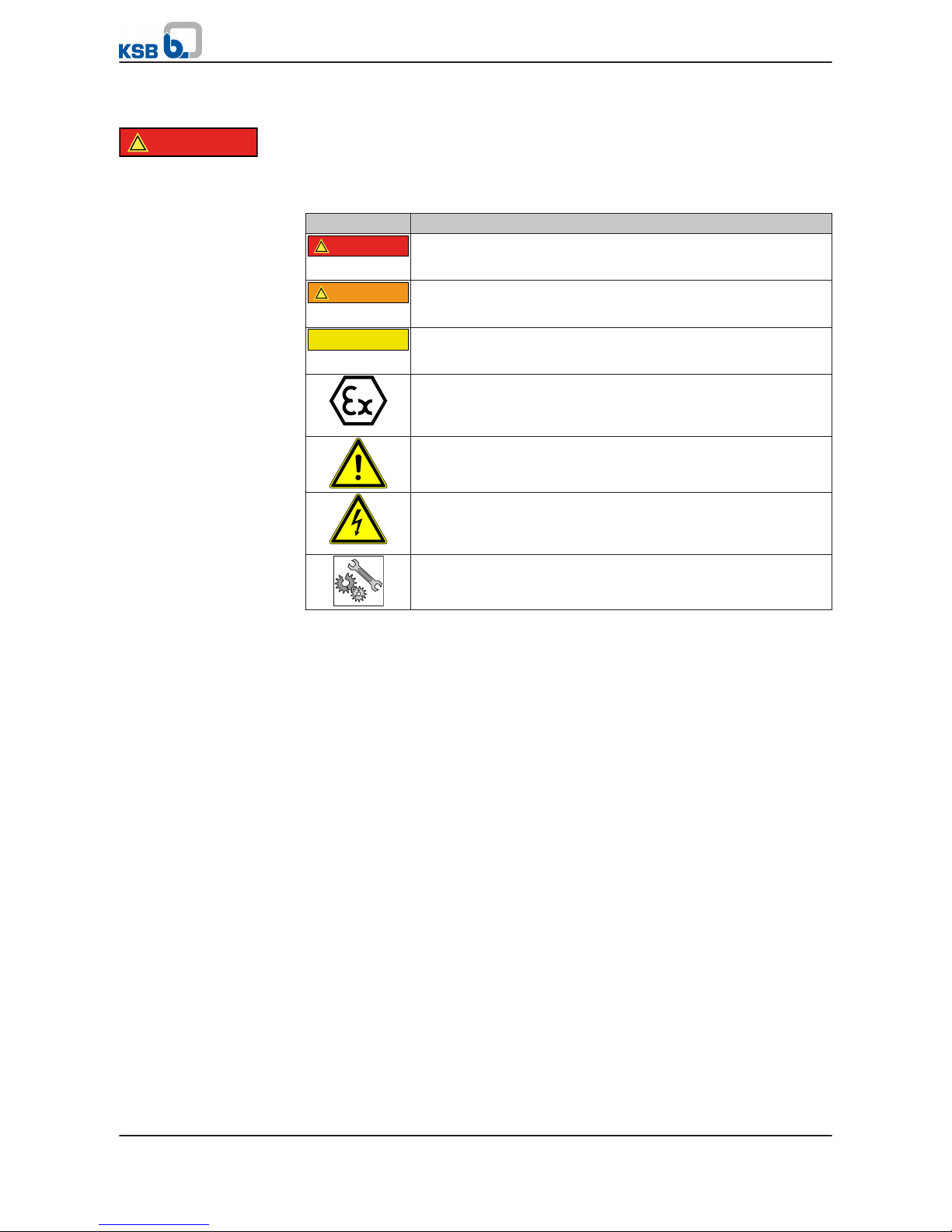
Table 3: Definition of safety symbols/markings
Symbol Description
!
DANGER
DANGER
This signal word indicates a high-risk hazard which, if not avoided,
will result in death or serious injury.
!
WARNING
WARNING
This signal word indicates a medium-risk hazard which, if not
avoided, could result in death or serious injury.
CAUTION
CAUTION
This signal word indicates a hazard which, if not avoided, could
result in damage to the machine and its functions.
Explosion protection
This symbol identifies information about avoiding explosions in
potentially explosive atmospheres in accordance with EC Directive
94/9/EC (ATEX).
General hazard
In conjunction with one of the signal words this symbol indicates a
hazard which will or could result in death or serious injury.
Electrical hazard
In conjunction with one of the signal words this symbol indicates a
hazard involving electrical voltage and identifies information about
protection against electrical voltage.
Machine damage
In conjunction with the signal word CAUTION this symbol indicates
a hazard for the machine and its functions.
2.2 General
This manual contains general installation, operating and maintenance instructions
that must be observed to ensure safe pump operation and prevent personal injury
and damage to property.
The safety information in all sections of this manual must be complied with.
This manual must be read and completely understood by the specialist personnel/
operators responsible prior to installation and commissioning.
The contents of this manual must be available to the specialist personnel at the site
at all times.
Information attached directly to the pump/motor must always be complied with and
be kept in a perfectly legible condition at all times. This applies to, for example:
▪ Arrow indicating the direction of rotation
▪ Markings for connections
▪ Name plate
The operator is responsible for ensuring compliance with all local regulations not
taken into account in this manual.
2.3 Intended use
The pump (set) must only be operated within the operating limits described in the
other applicable documents.
▪ Only operate pumps/pump sets which are in perfect technical condition.
▪ Do not operate the pump (set) in partially assembled condition.
▪ Only use the pump to handle the fluids described in the data sheet or product
literature of the pump model.
!
DANGER
2 Safety
8 of 64
UPA, UPZ, BSX
Page 9

▪ Never operate the pump without the fluid handled.
▪ Never operate the motor without fill liquid.
▪ Observe the minimum flow rates indicated in the data sheet or product literature
(to prevent overheating, bearing damage, etc).
▪ Observe the maximum flow rates indicated in the data sheet or product
literature (to prevent overheating, mechanical seal damage, cavitation damage,
bearing damage, etc).
▪ Do not throttle the flow rate on the suction side of the pump (to prevent
cavitation damage).
▪ Do not let the motor run in the wrong direction of rotation for more than two
minutes.
▪ Consult the manufacturer about any use or mode of operation not described in
the data sheet or product literature.
Prevention of foreseeable misuse
▪ Never open discharge-side shut-off elements further than permitted.
–
The maximum flow rate specified in the data sheet or product literature
would be exceeded.
– Risk of cavitation damage
▪ Never exceed the permissible operating limits specified in the data sheet or
product literature regarding pressure, temperature, etc.
▪ Observe all safety information and instructions in this manual.
2.4 Personnel qualification and training
All personnel involved must be fully qualified to transport, install, operate, maintain
and inspect the machinery this manual refers to.
The responsibilities, competence and supervision of all personnel involved in
transport, installation, operation, maintenance and inspection must be clearly
defined by the operator.
Deficits in knowledge must be rectified by means of training and instruction
provided by sufficiently trained specialist personnel. If required, the operator can
commission the manufacturer/supplier to train the personnel.
Training on the pump (set) must always be supervised by technical specialist
personnel.
2.5 Consequences and risks caused by non-compliance with these operating
instructions
▪ Non-compliance with these operating instructions will lead to forfeiture of
warranty cover and of any and all rights to claims for damages.
▪ Non-compliance can, for example, have the following consequences:
–
Hazards to persons due to electrical, thermal, mechanical and chemical
effects and explosions
– Failure of important product functions
– Failure of prescribed maintenance and servicing practices
– Hazard to the environment due to leakage of hazardous substances
2.6 Safety awareness
In addition to the safety information contained in this manual and the intended use,
the following safety regulations shall be complied with:
▪ Accident prevention, health and safety regulations
▪ Explosion protection regulations
▪ Safety regulations for handling hazardous substances
2 Safety
UPA, UPZ, BSX
9 of 64
Page 10

▪ Applicable standards and laws
2.7 Safety information for the operator/user
▪ The operator shall fit contact guards for hot, cold and moving parts and check
that the guards function properly.
▪ Do not remove any contact guards during operation.
▪ Provide the personnel with protective equipment and make sure it is used.
▪ Contain leakages (e.g. at the shaft seal) of hazardous fluids handled (e.g.
explosive, toxic, hot) so as to avoid any danger to persons and the environment.
Adhere to all relevant laws.
▪ Eliminate all electrical hazards. (In this respect refer to the applicable national
safety regulations and/or regulations issued by the local energy supply
companies.)
▪ If shutting down the pump does not increase potential risk, fit an emergency-
stop control device in the immediate vicinity of the pump (set) during pump set
installation.
2.8 Safety information for maintenance, inspection and installation work
▪ Modifications or alterations of the pump are only permitted with the
manufacturer's prior consent.
▪ Use only original spare parts or parts authorised by the manufacturer. The use of
other parts can invalidate any liability of the manufacturer for resulting damage.
▪ The operator ensures that all maintenance, inspection and installation work is
performed by authorised, qualified specialist personnel who are thoroughly
familiar with the manual.
▪ Only carry out work on the pump (set) during standstill of the pump.
▪ Prior to any dismantling work, disconnect the motor from the mains.
▪ The pump casing must have cooled down to ambient temperature.
▪ Pump pressure must have been released and the pump must have been drained.
▪ When taking the pump set out of service always adhere to the procedure
described in the manual.
▪ Decontaminate pumps which handle fluids posing a health hazard.
▪ As soon as the work is completed, re-install and/or re-activate any safety-relevant
and protective devices. Before returning the product to service, observe all
instructions on commissioning.
2.9 Unauthorised modes of operation
Never operate the pump (set) outside the limits stated in the data sheet and in this
manual.
The warranty relating to the operating reliability and safety of the supplied pump
(set) is only valid if the equipment is used in accordance with its intended use.
2 Safety
10 of 64
UPA, UPZ, BSX
Page 11

3 Transport/Temporary Storage/Disposal
3.1 Checking the condition upon delivery
1. On transfer of goods, check each packaging unit for damage.
2.
In the event of in-transit damage, assess the exact damage, document it and
notify KSB or the supplying dealer (as applicable) and the insurer about the
damage in writing immediately.
NOTE
The pump set is supplied by the manufacturer/supplier in packaging which largely
prevents sagging or other damage during transport and/or storage.
3.2 Transport
WARNING
Improper transport
Risk of squashing hands and feet!
Damage to the pump set!
▷ Always transport the pump set in horizontal position.
▷ Do not use electrical cables for transport.
▷ Gently set down the pump set.
▷ Observe the centre of gravity of the pump set and the weights indicated.
WARNING
Pump set tipping over or rolling off
Risk of personal injury!
▷ Always secure vertically positioned pump sets against tipping over.
▷ Always secure horizontally positioned pump sets against rolling off.
WARNING
Ambient temperature below the specified minimum
Danger of frost!
▷ Never subject the pump set to ambient temperatures which are lower than
those permitted for the drinking water/antifreeze mixture provided (see section
on drinking water/antifreeze mixture / order documentation).
NOTE
Take into account the unequal weight distribution between pump and motor.
Transporting the transport boxes
Submersible borehole pumps are supplied in appropriate packaging, e.g. transport
boxes, containing either the pump set or the pump and/or motor as individual
components (depending on the design). Use suitable lifting equipment to transport
the transport box to the place of installation or storage. Observe the marking on the
long side of the transport box! This marking indicates the centre of gravity.
Transport boxes
3 Transport/Temporary Storage/Disposal
UPA, UPZ, BSX
11 of 64
Page 12

Unpacking the pump set/pump/motor
WARNING
Unsecured cable drum
Risk of personal injury!
▷ Always secure the cable drum against tipping over.
▷ Always secure the cable drum against rolling off.
WARNING
Laying cables at temperatures below zero degrees
Damage to the cables!
▷ Observe the minimum permissible temperature at the cable surface of -25 °C for
moving cables.
▷ Observe the minimum permissible temperature at the cable surface of -40 °C for
stationary cables.
CAUTION
Excessive bending stress on the pump set
Damage to the pump set!
▷ Choose sling points which prevent excessive bending stress on the pump set.
Use suitable lifting equipment for lifting the pump set out of the packaging and
transporting it(⇨ Section 4.7 Page 19
) Use suitable lifting tackle for lifting the pump
set out of the packaging and transporting it, e. g. lifting straps. Sling points: in the
middle of the motor and at the upper end of the pump.
Fig. 1: Transporting the pump set by crane
✓ Suitable lifting equipment and lifting tackle are available.
✓ The surface on which the pump set is to be positioned is solid and level.
✓ Securing means, e.g. timber wedges are on hand.
1.
Gently set down the transport box.
2. Open the transport box.
3. Take out the power cable and put it down.
4. Position the lifting tackle allowing for balanced lifting. Normally, the centre of
gravity of the pump set will be in the motor area. Watch any add-on parts, such
as piping and cables!
5. Use the lifting equipment to lift the pump set out and position it on a solid and
level surface.
6. Use appropriate means to secure the pump set against rolling off.
Unpacking
3 Transport/Temporary Storage/Disposal
12 of 64
UPA, UPZ, BSX
Page 13
3.2.1 Pulling the pump/motor/pump set upright
WARNING
Incorrect positioning
Personal injury and damage to property!
▷ Position the pump set vertically with the motor below.
▷ Use appropriate means to secure the pump set against overturning and tipping
over.
▷ Refer to the weights given in the data sheet.
WARNING
Improper handling when setting the pump set down in a vertical/horizontal
position
Personal injury and damage to property!
▷ Use appropriate means to secure the pump set against overturning, tipping
over and rolling off.
▷ Maintain adequate safety distance during lifting operations (load may swing
when being lifted).
▷ Use additional supports for the transport holder to secure the pump set against
overturning.
WARNING
Improper handling of the power cable when placing the pump set in vertical
position or transporting it
Personal injury and damage to property!
▷ Secure power cables against falling down.
CAUTION
Improper storage
Damage to the power cables!
▷ Support the power cables at the cable entries to prevent permanent
deformation. Observe the minimum bending radius2) of the cables.
▷ Only remove the protective caps from the power cables at the time of
installation.
CAUTION
Excessive bending stress on the pump set
Damage to the pump set!
▷ Choose sling points which prevent excessive bending stress on the pump set.
✓ Suitable lifting equipment for the total weight has been selected and is on hand.
1.
Fasten to a suitable lifting accessory, e.g. mounting plate.
2. Attach the lifting equipment, pull the pump/motor/pump set upright, and
secure it against tipping over.
3.3 Storage and preservation
If commissioning is to take place some time after delivery, we recommend that the
following measures be taken:
2)
See cable manufacturer's documentation or DIN VDE 0298-3.
3 Transport/Temporary Storage/Disposal
UPA, UPZ, BSX
13 of 64
Page 14
WARNING
Pump set tipping over or rolling off
Risk of personal injury!
▷ Always secure vertically positioned pump sets against tipping over.
▷ Always secure horizontally positioned pump sets against rolling off.
WARNING
Ambient temperature below the specified minimum
Danger of frost!
▷ Never subject the pump set to ambient temperatures which are lower than
those permitted for the drinking water/antifreeze mixture provided (see section
on drinking water/antifreeze mixture / order documentation).
WARNING
Laying cables at temperatures below zero degrees
Damage to the cables!
▷ Observe the minimum permissible temperature at the cable surface of -25 °C for
moving cables.
▷ Observe the minimum permissible temperature at the cable surface of -40 °C for
stationary cables.
CAUTION
Improper storage
Damage to the power cables!
▷ Support the power cables at the cable entries to prevent permanent
deformation. Observe the minimum bending radius3) of the cables.
▷ Only remove the protective caps from the power cables at the time of
installation.
Store the submersible borehole pumps as follows:
1.
In its original packaging: horizontally
2. Without packaging: vertically (with the motor below)
3. In a dry environment
4. Protected against direct sunlight and heat
5. Protected against dirt and dust
6. Protected against freezing
7. Protected against vermin
Further information on storing the pump set after use (⇨ Section 7.5 Page 49).
3.4 Return to supplier
WARNING
Ambient temperature below the specified minimum
Danger of frost!
▷ Never subject the pump set to ambient temperatures which are lower than
those permitted for the drinking water/antifreeze mixture provided (see section
on drinking water/antifreeze mixture / order documentation).
1. Clean the pump set properly from the outside.
3)
See cable manufacturer's documentation or DIN VDE 0298-3.
3 Transport/Temporary Storage/Disposal
14 of 64
UPA, UPZ, BSX
Page 15
2. Always flush and clean the pump, particularly if it has been used for handling
noxious, explosive or other hazardous fluids.
3.
If the fluids handled by the pump set leave residues which might lead to
corrosion damage when coming into contact with atmospheric humidity, or
which might ignite when coming into contact with oxygen, the pump set must
also be neutralised, and anhydrous inert gas must be blown through the pump
for drying purposes.
4. Always complete and enclose a certificate of decontamination when returning
the pump (set).
Always indicate any safety and decontamination measures taken.
NOTE
If required, a blank certificate of decontamination can be downloaded from the
KSB web site at: www.ksb.com/certificate_of_decontamination
3.5 Disposal
WARNING
Fluids handled posing a health hazard
Hazard to persons and the environment!
▷ Collect and properly dispose of flushing liquid and any liquid residues.
▷ Wear safety clothing and a protective mask, if required.
▷ Observe all legal regulations on the disposal of fluids posing a health hazard.
1. Dismantle the pump (set).
Collect greases and other lubricants during dismantling.
2.
Separate and sort the pump materials, e.g. by:
- Metals
- Plastics
- Electronic waste
- Greases and other lubricants
3. Dispose of materials in accordance with local regulations or in another
controlled manner.
3 Transport/Temporary Storage/Disposal
UPA, UPZ, BSX
15 of 64
Page 16
4 Description of the Pump (Set)
4.1 General description
Pump for handling clean or slightly contaminated water.
Verify the fluid composition against the data sheet.
Not approved for handling explosive fluids or for forming part of an explosion-proof
system!
4.2 Designation
Submersible borehole pump
Example: UPA 250C - 150 / 5b
Table 4: Key to the designation
Code Description
UPA Pump type
250 Nominal size [mm]
C Design status
150 Flow rate at best efficiency point [m³/h]
5 Number of stages
b Reduced impeller diameters
Submersible borehole pump
Example: BRZS 535 / 5
Table 5: Key to the designation
Code Description
B R Pump type
Z Nominal size
S Design with suction impeller
535 Hydraulic code
5 Number of stages
Submersible motor
Example: VBD FV 31 - 30 5
Table 6: Key to the designation
Code Description
V Motor size, e.g. V = 14 inch
B Number of poles, e.g. B = 2 poles
D Design status
FV Length of core pack
31 Maximum rated power
30 Voltage, e.g. 30 = 3 kV
5 Frequency, e.g. 5 = 50 Hz
4 Description of the Pump (Set)
16 of 64
UPA, UPZ, BSX
Page 17
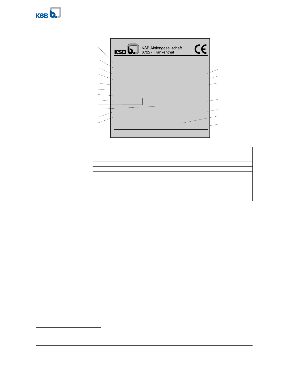
4.3 Name plate
Serial No. 9971276748-000100
1
2
3
4
5
6
13
14
15
Pump RE 555/3
Qmin
Qmax
Q
Motor
340 KW
3300 V
Temp.
Min. flow velocity past the motor = 0.2 m/s
EN 60034-1
IP 68
Mat. No.: 01 000 854 ZN 3823 - D 88
300 L/MIN
1170 L/MIN
879.6 L/MIN
Hmax
Hmin
H
108 M
69 M
92.7 M
3~ XMD HQ 37-335
50 Hz
86 A 0.77 COS
20 °C max. 1467 rpm
7
8
11
12
9
10
16
17
18
19
Fig. 2: Name plate (example)
1 Order number 2 Pump designation
3 Minimum flow rate 4 Maximum flow rate
5 Flow rate at duty point 6 Motor designation
7 Rated power 8 Voltage
9 Frequency 10 Amperage
11 Maximum fluid temperature 12 Minimum available flow along the
motor
13 Maximum head 14 Minimum head
15 Head at duty point 16 Power factor
17 Speed 18 VDE Standard
19 Motor enclosure
4.4 Design details
Pump design
▪ Centrifugal pump
▪ Single-stage or multi-stage
▪ Radial or mixed flow versions
▪ Single-entry or double-entry
▪ Shroud or ring-section design
▪ With non-return valve or connection branch
▪ Pump connection with threaded or flanged end
▪ Rigid connection between pump and motor
Motor design
▪ Submersible motor in squirrel-cage design
▪
Motor shaft4) protected by sealed sleeve coupling
▪ Rubber expansion diaphragm for pressure equalisation
▪ Thrust bearing with tilting pads to absorb the pump's hydraulic thrust
▪ Single mechanical seal
4)
For motor sizes V, X, Z and E
4 Description of the Pump (Set)
UPA, UPZ, BSX
17 of 64
Page 18
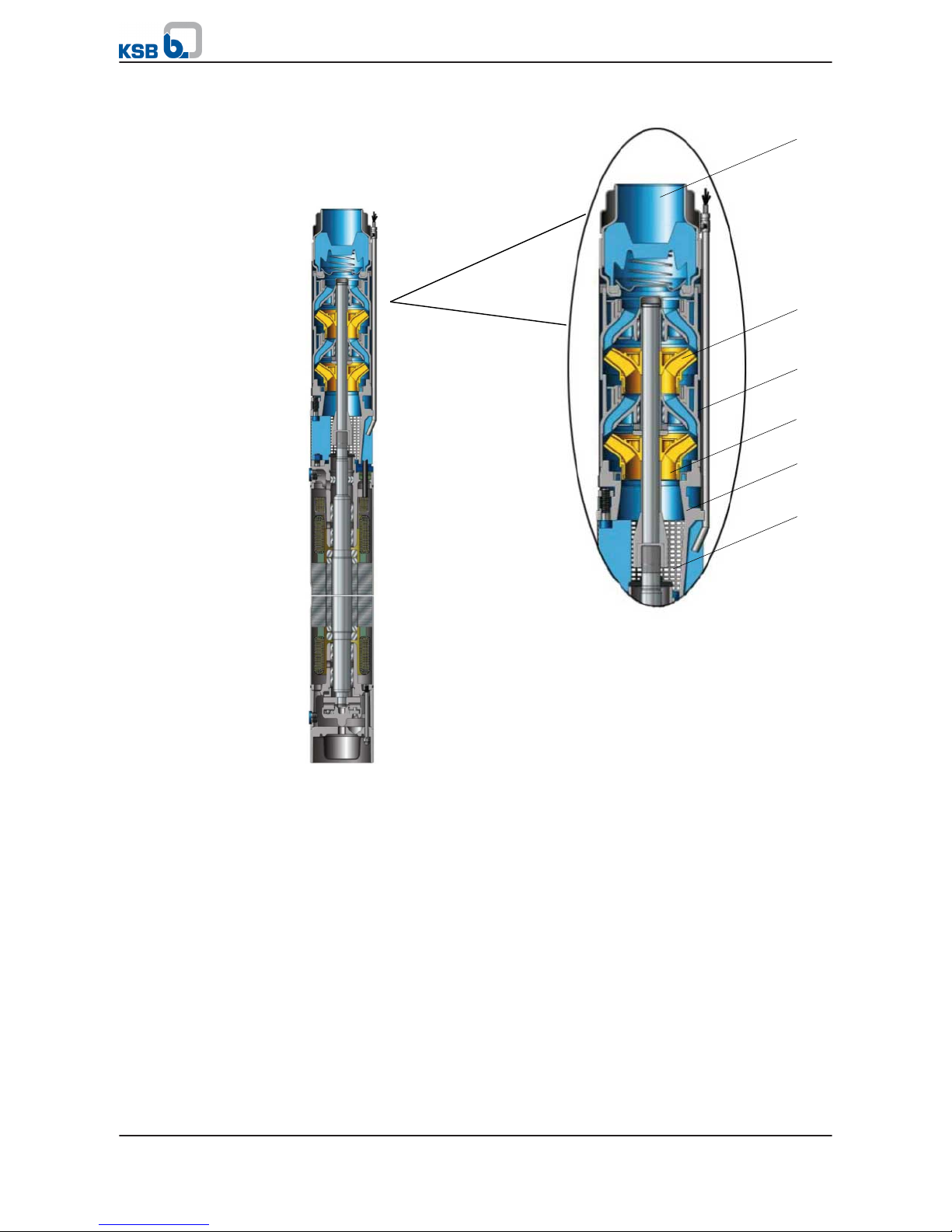
4.5 Configuration and function
6/7
4
5
3
2
1
Fig. 3: Sectional drawing, example of a UPA
Pump and motor are connected by a rigid coupling. The stage casings are supported
by straps or stud bolts. A suction strainer at the suction casing protects the pump
from coarse particles in the fluid. The pump set is connected to the piping via a nonreturn valve or connection branch with either internal thread or flanged end
(optional).
The fluid flows along the motor and enters the suction casing (2) through the suction
strainer (1). It is accelerated outward by the suction impeller (3). In the flow passage
of the stage casing (4) the kinetic energy of the fluid is converted into pressure
energy, and the fluid is routed to the next impeller (5). This process is repeated in all
stages until the fluid has passed the last impeller (5). It is then guided through the
integrated non-return valve to the connection branch (7), where it leaves the pump.
The integrated non-return valve prevents uncontrolled backflow of the fluid.
4.6 Scope of supply
Depending on the model, the following items are included in the scope of supply:
▪
Pump set with motor lead
Optional: pump and/or motor as individual units
Design
Function
4 Description of the Pump (Set)
18 of 64
UPA, UPZ, BSX
Page 19

▪ Electric cable
Optional: connected or supplied loosely
▪ Tools for filling the motor
▪
Separate name plate
5)
▪ Accessories, such as:
–
Cable connector
– Cable ties
– Cooling, suction or pressure shroud
– Bearing pedestals
– Electrical protection devices
– Automatic control units
4.7 Dimensions and weights
For dimensions and weights please refer to the data sheet of the pump (set).
5)
To be attached outside the place of installation, e.g. control panel, pipeline or mounting bracket.
4 Description of the Pump (Set)
UPA, UPZ, BSX
19 of 64
Page 20

5 Installation at Site
5.1 General information/Safety regulations
DANGER
Using damaged cables in a well
Electric shock!
▷
Do not kink cables (observe the minimum bending radius 6) of the cable) or
drag the cables over sharp edges.
▷ Use cable ties or other suitable fasteners to fasten the power cables as well as
any measuring and control cables to the riser or piping every three meters.
▷ Do not use any tools, equipment or accessories with sharp edges (e.g. sharp-
edged pipe sockets) during installation.
WARNING
Pump set falling into the well
Personal injury or persons being dragged down by uncontrolled cable movements!
Damage to the pump set and the well!
▷ Securely store the cable with extension lead. Keep at a safe distance during
installation.
▷ Secure the pump set during the entire installation procedure.
▷ Dimension any securing devices (supporting clamps, supports, etc.) so that they
can carry all weights during the installation.
WARNING
Persons could fall into unsecured wells/reservoirs/tanks
Risk of personal injury!
▷ During installation work, take suitable precautions to protect anyone from
falling into an open well/reservoir/tank.
▷ Suitably fence off the work area.
WARNING
Improper handling when setting the pump set down in a vertical/horizontal
position
Personal injury and damage to property!
▷ Use appropriate means to secure the pump set against overturning, tipping
over and rolling off.
▷ Maintain adequate safety distance during lifting operations (load may swing
when being lifted).
▷ Use additional supports for the transport holder to secure the pump set against
overturning.
WARNING
Improper handling of the power cable when placing the pump set in vertical
position or transporting it
Personal injury and damage to property!
▷ Secure power cables against falling down.
6)
See cable manufacturer's documentation or DIN VDE 0298-3.
5 Installation at Site
20 of 64
UPA, UPZ, BSX
Page 21

WARNING
Laying cables at temperatures below zero degrees
Damage to the cables!
▷ Observe the minimum permissible temperature at the cable surface of -25 °C for
moving cables.
▷ Observe the minimum permissible temperature at the cable surface of -40 °C for
stationary cables.
NOTE
Do not expose power cables to direct sunlight.
NOTE
A separate name plate is included in KSB's scope of supply.
This name plate must be attached in a clearly visible position outside the place of
installation, e.g. at the control panel, pipeline or mounting bracket.
NOTE
The motor lead is selected for submerged operation and must be completely
submerged, including the cable connector.
See order documentation for any other use!
5.2 Preparing the installation
5.2.1 Checking the installation conditions
Prior to starting with the installation, check compliance with the particular
framework conditions required for a trouble-free operation of the submersible
borehole pump. To do so, verify the order data and/or delivery data against the
constructional plans, the operating conditions and the operating limits of the pump
set.
1.
Has this pump set been ordered for the required installation position?(⇨ Section
5.2.2 Page 22)
2. Does the material variant of the pump set match the installation conditions?
3. Can the required flow velocity past the motor be guaranteed?
4. Is the required minimum submergence met during operation? (⇨ Section 6.2.3.1
Page 41)
5. Is the sand content of the fluid to be handled below the specified maximum?(⇨
Section 6.2.3.2 Page 42)
6. Is the temperature of the fluid to be handled below the specified maximum?
7. If fluids liable to form deposits are handled, is temperature monitoring provided?
8. Will the motor lead and the cable connector be completely submerged?
General information on the system design
Select a pump set suspension arrangement whose design and dimensions allow for all
static and dynamic forces to be absorbed. Tightly fasten the supporting clamps or
flanges to the well head so that they cannot move or lift off the well head.
System-induced vibrations must not be transmitted to the pump set. The system must
be designed in such a way that vibrations are not amplified. Abrupt pressure
equalisation processes (pressure surges), in particular, present a hazard for the pump
set. Take suitable precautions (e.g. fit expansion joints, air vessels).
Well head
Vibrations
5 Installation at Site
UPA, UPZ, BSX
21 of 64
Page 22

Do not install the pump set with the suction strainer exactly at the level of the well
screen/filter. Excessive flow in the area of the well screen/filter entails the risk of
large amounts of sand being transported, which will cause excessive wear in the
pump.
Verify the well dimensions.
Pumps which are to be installed in a pump sump are always designed with a suction
or cooling shroud.
The pump set must not sit on the base of the well!
The pump set must not touch the well and tank walls! Use a centring device, if
required!
Prevent adjacent pump sets from influencing each other.
Provide an even approach flow in the suction area and do not obstruct it with any
structural components or installations.
Air intake from an inlet arranged above the water level is not permitted.
5.2.2 Checking the installation position
WARNING
Impermissible installation position
Damage to the machine! Damage to the bearings!
▷ For angled installation, always install the pump set with a rising slope towards
the discharge side.
The submersible borehole pump can be installed in a vertical or, depending on the
number of stages, also in an angled or horizontal position.
1.
Never install horizontally a pump set which has been selected for vertical
installation!
2. Never install the pump set with the pump at the lowest point.
A1
A2
B
C
Fig. 4: Checking the installation position
A1, A2 Permissible installation position
B Permissible installation position, if approved in the order documentation
C Impermissible installation position
Sand deposits
Narrowing
Installation conditions
5 Installation at Site
22 of 64
UPA, UPZ, BSX
Page 23

5.2.3 Checking the motor fill
DANGER
Unfilled or insufficiently filled motor
Damage to the motor winding!
▷ Never install and run the motor without sufficient motor fill.
▷ Observe the information sticker on the motors and top up the motor fill as
instructed.
DANGER
Unfilled or insufficiently filled motor
Winding damage!
Corrosion damage!
▷ Observe the information sticker on the motor and top up the motor fill as
instructed.
WARNING
Drinking water/antifreeze mixture could escape
Hazardous to persons and the environment!
▷ Wear safety glasses and protective gloves when topping up, checking and
draining the motor fill.
▷ Observe the national health and safety regulations.
▷ Observe all legal regulations on the disposal.
CAUTION
Freezing of motor fill
Motor damage!
▷ Match the mixing ratio of drinking water / antifreeze agent to the expected
temperatures.
▷ Always protect water-filled motors against frost.
▷ Provide frost-proof storage.
NOTE
The loss of a few drops of liquid fill will not impair the motor function. If any larger
amounts of leakage are suspected, the motor fill must be checked.
Information sticker / motor fill
Submersible motors are filled with a liquid based on drinking water. A distinction is
made between filled and unfilled motors, marked by colour-coded information
stickers attached to the motor, depending on the motor type series. Motors which
are supplied filled with a mixture of drinking water / antifreeze agent must not be
filled with pure drinking water at a later stage. Pure drinking water can only be filled
into motors which have not been filled before.
Table 7: Type of motor fill
Sticker colour Supplied condition Motor fill
Green Filled Drinking water / antifreeze mixture (1,2 propylene glycol)
Red Unfilled Drinking water
or drinking water / antifreeze mixture (1,2 propylene glycol)
5 Installation at Site
UPA, UPZ, BSX
23 of 64
Page 24

5.2.3.1 Checking the fill level
WARNING
Drinking water/antifreeze mixture could escape
Hazardous to persons and the environment!
▷ Wear safety glasses and protective gloves when topping up, checking and
draining the motor fill.
▷ Observe the national health and safety regulations.
▷ Observe all legal regulations on the disposal.
WARNING
Screw plugs subjected to pressure
When opening screw plugs, liquid might spurt out!
▷ Wear safety goggles and protective clothing, if required.
▷ Open the screw plug slowly.
a
b
c
a
b
c
For motor type series T For motor type series V, X, Z, E
a) Filler opening
b) Vent opening
c) Filling funnel
a) Filler opening
b) Vent opening
c) Filling funnel
1. Set down the motor or pump set in a vertical position. Secure it against tipping
over.
2.
Undo the two screw plugs (a and b) and remove them together with the seal
elements.
⇨ If the liquid level is visible in one of the two openings, the motor fill is
sufficient.
⇨ If the fill level is not visible, fill the motor sufficiently. (⇨ Section 7.4.1 Page
48)
3. Screw the screw plugs (a and b) back in together with the sealing elements.
Check the screw plugs for tightness. Make sure that the contact faces are clean
and that the joint ring is inserted and free from damage.
1. Suspend the motor or pump set from a crane. Fasten the motor or pump set to
the floor and secure it against slipping.
2.
Carefully lower the crane to slightly tilt the motor or pump set.
3. Monitor the screw plugs for escaping fluid.
4. If required, fit new sealing elements.
5.2.4 Installing water storage tanks
If the pump set is intended for horizontal installation, the motor has to be fitted with
water storage tanks.
Checking the screw plugs
5 Installation at Site
24 of 64
UPA, UPZ, BSX
Page 25

✓ The motor has been set down in a horizontal position on a level and solid
surface. It has been secured against rolling off.
✓ Position the motor with the connections for the water storage tanks at the
highest point.
✓ The water storage tanks are on hand.
✓ The motor fill has been checked with the motor in vertical position.
✓ Suitable liquid for topping up the motor fill has been prepared.
1.
Remove the screw plugs from the top and bottom of the stator case. Remove
the joint rings.
2. Insert the water storage tanks (59-33) with new joint rings (411.51) into the
stator and screw them in tightly.
3. Fill the water storage tanks with the specified liquid fill until they overflow.
4. Close both water storage tanks with a screw plug with integrated vent valve
(741) and joint ring (411.51).
5.2.5 Preventing backflow
CAUTION
Uncontrolled backflow of the fluid from the riser
Damage to the pump set!
▷ Prevent any uncontrolled backflow of the fluid handled with suitable means.
▷ Make sure that backflow of the fluid handled is slow and controlled, so that the
pump rotor does not start to rotate, e.g. by throttling the discharge-side gate
valve accordingly.
The submersible borehole pumps are generally fitted with an integrated non-return
valve.
On pump sets without non-return valve the operator must prevent any uncontrolled
backflow of the fluid, e.g. by structural means. Otherwise the pump could be
operated in the wrong direction of rotation and critical speeds could be exceeded.
5.2.6 Calculating the total weight
Suitable lifting equipment (e.g. tripod, crane, etc.) is required for installing and
removing submersible borehole pumps. The load-carrying capacity of the lifting
equipment must be larger than the weight of the pump set + the riser7) + the water
column 8) in the riser + the power cable + the cable ties. For the weights refer to the
order documentation, the product literature of the sub-suppliers and the following
table.
Table 8: Weight of the water column per 1 metre of the riser
Pipe diameter [mm]
Pipe diameter [inch]
50
2"
803"1004"1255"1506"2008"250
10"
300--350--400
--
Weigh
t [kg]
2 5 8 12 18 32 49 72 98 125
741
411.51
903.53
59-33
411.51
Fig. 5: Installing water
storage tanks
7)
See product literature of the riser used.
8)
Applies to pumps with non-return valve if no other measures to drain the riser have been taken
5 Installation at Site
UPA, UPZ, BSX
25 of 64
Page 26

5.2.7 Electric wiring
DANGER
Unqualified personnel connecting extension leads
Installation in a well - electric shock!
▷ The extension lead must be connected by a professional electrician only.
▷ The cable ends must be dry and clean.
DANGER
Earth conductor not properly connected
Danger of death from electric shock!
▷ Never operate the motor without earth conductor.
▷ The earth conductor must be connected by a professional electrician only.
NOTE
The motor lead is selected for submerged operation and must be completely
submerged, including the cable connector.
See order documentation for any other use!
Submersible motors are supplied fitted with a motor lead. The motor lead has been
extended with a suitably sized extension cable to meet the length required for the
specific installation. Unless otherwise indicated, the motor lead is designed for
submerged operation only. To meet this condition the cable connector also has to be
completely submerged.
Extension cables connected by KSB
If agreed with KSB, the extension cable can be supplied connected to the motor lead
with a watertight cable connector.
▪ Unless otherwise specified in the order documentation, KSB's extension cables
are designed for:
–
Being laid in free air
– A voltage drop along the lead of ᅀ U ≦3 %
For any other ways of laying cables, e.g. in cable ducts, etc. observe the
information on the maximum current-carrying capacity as per the applicable
directives.
Extension cables connected by the operator
If the supplied extension cable is to be connected at the site, observe the following
points:
1. Observe the installation instructions of the cable connector to be used.
2. If the operator is responsible for connecting an extension cable, make sure the
extension cable is selected and dimensioned for a maximum voltage drop of ≦3
%. The extension cable has to be approved for the applicable operating
conditions.
3. In 4-core leads the earth conductor is part of the power cable and must also be
connected in the cable connector when connecting an extension cable.
4. 3-core motor leads do not include an earth conductor. A separate earth
conductor is connected on the outside of the motor. The earth conductor has to
be extended separately.
If no earth conductor is provided, the operator shall be responsible for earthing
the motor externally. (Core size corresponding to phase conductor, min. 4 mm2)
5. Connect the shield of shielded extension cables to the earth conductor. 3-core
motor leads as described in paragraph 4 must be earthed externally; connect the
shield of the extension cable to the earth conductor.
5 Installation at Site
26 of 64
UPA, UPZ, BSX
Page 27

6. Transfer the core identification of the motor lead to the cores of the extension
cable. Make sure the colour codes match when connecting the cores.
The core codes depend on the wiring type of the motor:
Table 9: Core codes
Motors for DOL starting with 1 lead
U V W
.
Motors for DOL starting with 2 parallel leads
U1 - 1 V1 - 1 W1 - 1 U1 - 2 V1 - 2 W1 - 2
5.2.8 Measuring the insulation resistance
DANGER
Hazardous voltage during and after measurement
Danger of death from electric shock!
▷ Do not touch the contact points during and immediately after measurement.
▷ Insulation resistance measurement must be effected by a trained electrician
only.
Measure the insulation resistance prior to installation and prior to connection to the
power supply.
Insulation resistance measurement must be effected by a trained electrician only.
Prior to the measurement, ensure compliance with the operating instructions of the
device for measuring the insulation resistance.
✓ An insulation resistance measuring device with a measuring voltage of 1000 V DC
to 2500 VD C max. is available.
✓ The contact points are clean and dry.
1.
Measurement period: 1 minute
9)
2.
Minimum insulation resistance at 20 °C - 30 °C: > 200 MOhm
V WU
Risol
(MΩ)
M 3~
V1-1 W1-1U1-1
Risol
(MΩ)
M 3~
V1-2 W1-2U1-2
1 lead 2 leads (parallel)
5.3 Installing the pump set in vertical position
NOTE
Observe all safety instructions contained in this manual for the following
installation instructions. (⇨ Section 5.1 Page 20
)
9)
The measured value must be steady; a longer measurement period might be needed for larger cable cross-sections.
5 Installation at Site
UPA, UPZ, BSX
27 of 64
Page 28

Suspend the submersible borehole pump from the riser to transport it to its actual
place of installation/operation. The riser can differ in design and material.
Consequentially, the installation and application options also differ. Always observe
the installation instructions of the respective riser when installing a submersible
borehole pump! The riser always has to be designed for the maximum forces, torques
and pressures in the system.
General information of lowering the pump set into the well
▪ It is recommended to fit a centring device to prevent the pump set and the walls
of the well from any damage during installation.
▪ Fit cable ties every three metres to protect the power cable against any damage.
Cable ties are suitable for metal risers and/or thick-walled plastic risers. On all
other riser types, the power cable also has to be secured every three metres.
▪ Tighten the cable ties firmly to prevent the power cable from slipping
downwards by its own weight! Otherwise, the cable could be affected by
impermissibly high tensile stress.
WARNING
Installing pipe sections of extensive length
Impermissible bending of the pump set when pulling it upright!
▷ The length of the first pipe section must not exceed two metres.
Installation example with a metal riser (pipes)
✓ Suitable lifting equipment for the total weight has been selected and is on hand.
(⇨ Section 5.2.6 Page 25)
✓ The motor fill has been checked and topped up, if required.
✓ Any extension cables have been properly connected to the power cable as well as
to the measuring and control cables.
✓ The pump set has been placed in horizontal position in a level assembly area and
is protected against rolling off.
✓ Cable ties to securely fasten the power cable and any measuring and control
cables are on hand.
✓ A sealing agent is available.
✓ A mounting plate, pairs of supporting clamps and beams have been selected for
the total weight(⇨ Section 5.2.6 Page 25)and are on hand.
✓
Risers with recesses in the flanges
10)
are on hand.
1. For flanged risers:
Bolt the first pipe section (max. length 2 m) to the connection branch. Fasten
the mounting plate to this pipe section.
2.
Fasten the first pair of supporting clamps below the upper flange.
NOTE
On threaded risers fit an anti-rotation device to prevent the pump set from
unscrewing itself from the threaded riser during start-up.
1. For threaded risers:
Apply a sealing agent and screw the first pipe section (max. length 2 m) into the
connection branch. Secure the connection with the two supplied securing
screws. For this purpose, drill a shallow hole into the threaded end of the pipe
section, taking care not to drill through the threaded end. Insert the locking
screws with thread-locking compound in such a way that their tips rest lightly
but do not press on the threaded pipe end! Allow time for the sealing agent to
cure. The connection is now sufficiently secured against loosening.
10)
Applies to flanged risers only
5 Installation at Site
28 of 64
UPA, UPZ, BSX
Page 29

2. Use cable ties to attach the power supply cable as well as any control and
measuring cables to the riser approximately 0.5 m above the lower flange.
3.
Place two sturdy beams across the well opening.
4. Pull the pump set into upright position with the lifting equipment.
5. Attach the pump set to the crane hook (e.g. mobile crane) by the mounting
plate and lower it into the well until the first pair of supporting clamps rests on
the beams.
6. Remove the mounting plate and fasten it to the second riser.
7. Fasten a second pair of supporting clamps to the second riser.
8. Use the lifting equipment to lower the second riser onto the first riser, and
install it.
9. Undo the first pair of supporting clamps and lower the pump set until the
second pair of supporting clamps rests on the beams.
10. Repeat these steps for every pipe section, lowering the pump set into the well
until the installation depth He is reached.
H
e
5.3.1 Attaching the cable ties
The cables shall be fixed to the riser pipe by a cable tie each on both sides of the riser
pipe flange or socket. Attach a cable tie every 3 metres. Implement this arrangement
over the entire length of the riser.
2
3
4
1
5
Sizes 2, 3, 3a, 3b, 4
1 = turnbuckle (reusable)
2 = cable guard
3 = power cable
4 = metal strap
5 = riser
5 Installation at Site
UPA, UPZ, BSX
29 of 64
Page 30

1. Cut metal strap (4) to the required length L (L = circumference of riser pipe +
approx. 200 mm allowance) and bend both ends inwards by approx. 100 mm.
2.
Fully open the turnbuckle (1) and attach it to one end of the metal strap.
3. Place the cable guard (2) around the power cable (3). Guide it around the riser
(5) together with the metal strap (4). Then attach the other end of the
turnbuckle (1) to the metal strap (4).
4. Tighten the turnbuckle (1) with a screwdriver so that the power cable (3) cannot
slip downwards by its own weight!
5.4 Installing the pump set in a horizontal position
NOTE
Observe all safety instructions contained in this manual for the following
installation instructions.(⇨ Section 5.1 Page 20)
WARNING
Installation on mounting surface which is unsecured and cannot support the load
Personal injury and damage to property!
▷ Use a concrete of compressive strength class C12/15 which meets the
requirements of exposure class XC1 to EN 206-1.
▷ The mounting surface must have set and must be completely horizontal and
even.
▷ Observe the weights indicated.
CAUTION
Temperature and pressure increase of the motor fill
Damage to the motor!
▷ Always protect non-flooded pump sets against direct exposure to sun.
NOTE
Only install pump sets in horizontal position if they have been approved for this
type of installation.
Submersible borehole pumps can be installed in a horizontal position, provided the
pump set has been approved for this type of installation. (See data sheet.)
The required accessories depend on the weight and the overall length of the pump
set. If agreed with KSB, the pump set is supplied with the accessories for the required
installation type already fitted.
For assembly at the site:
It is imperative to use original accessories (bearing pedestals, supporting frames,
pressure shroud).
5.4.1 Installing the pump set on supporting frame and bearing pedestal
NOTE
Fasten the power cable as well as any measuring and control cables to the piping at
least every three metres as well as upstream and downstream of any pipe bends by
means of cable ties or other suitable fasteners. Prevent any fluttering of the cables
caused by the water flow. This applies especially to any other types of cable guide;
use a protecting tube, if required.
5 Installation at Site
30 of 64
UPA, UPZ, BSX
Page 31

1
2
3
4
Fig. 6: Installation example with supporting frame and bearing pedestal
1 Motor 2 Pump
3 Supporting frame 4 Pedestal
Observe the following positions of the supporting frame and bearing pedestal:
Supporting frame for the motor: Mounting clamps at the casing flanges
Bearing pedestal for the pump: Last stage or non-return valve / connection branch.
✓ The structural dimensions have been verified.
✓ The water storage tanks have been installed.
✓ The motor fill has been checked and topped up, if required.
✓ Any extension cables have been connected to the power cable as well as to the
measuring and control cables.
1.
Undo the ties holding the cable guard. Remove the cable guard.
2. Fasten the supporting frame and bearing pedestals to the pump set. Position
and align the assembly on the foundation/floor.
3. Mark and drill the holes for the fixing bolts on the foundation and fasten the
pump set with the supporting frame/pedestals on the foundation.
4. Run the power cable through the foot of the pump bearing pedestal and fasten
it to the pump (approximately in the middle of the pump's overall length) and
the non-return valve / connection branch with cable ties.
Make sure the cable is securely fastened to prevent it from fluttering in the
water flow. Use a protective tube, if necessary!
NOTE
Fit an expansion joint between the piping and the pump set to prevent any piping
forces and vibrations from affecting the pump set.
5. Install the piping.
6.
Securely fasten the power cable as well as any measuring and control cable to
the piping with cable ties or use other suitable cable guides.
5.4.2 Installing the pump set in a suction, pressure or cooling shroud
For special operating conditions, submersible borehole pumps can be equipped with
a suction, pressure or cooling shroud; see order documentation or data sheet.
In such cases, always refer to the additional documentation supplied with the
delivery. See the operating instructions of the accessory "Suction, pressure or cooling
shroud".
1 3 2
Fig. 7: Example: pressure shroud
1 Motor 2 Pump
3 Pressure shroud
5 Installation at Site
UPA, UPZ, BSX
31 of 64
Page 32

5.5 Installing the pump set in an angled position
NOTE
Observe all safety instructions contained in this manual for the following
installation instructions.(⇨ Section 5.1 Page 20
)
The pump sets are suitable for angled installation, provided they have been selected
for this type of installation. See order documentation or data sheet.
Angled installation of a submersible borehole pump always requires structural
adjustments. For angled installation, always refer to the additional documentation
supplied with the delivery.
Permissible installation positions:
A1
A2
B
C
Fig. 8: Installation position
Table 10: Selection table
A1 Permissible up to
maximum 3°
Installation see section: Installing the pump set in
a vertical position (⇨ Section 5.3 Page 27
)
A2 Permissible up to
maximum 3°
Installation see section: Installing the pump set in
a horizontal position
B Permissible installation position, if approved in the order documentation
C Impermissible The pump set must not be installed in this
position.
5.6 Notes on electrical connection
KSB's submersible borehole pumps > 1000 V are wired for DOL starting. During startup and run-up the voltage must not fall below the value specified in the order
documentation.
If this starting method is not permitted by the power supply utility, starting devices
to reduce starting currents must be provided (e.g. autotransformers, starting resistors
or soft starters ).
General information on the motor
Motor protection
Provide a temperature-compensated overcurrent relay of tripping class 10 or 10 A as
motor protection. If an earth leakage relay is used, it must be fitted in the motor
power circuit.
5 Installation at Site
32 of 64
UPA, UPZ, BSX
Page 33

Rating
The rating specified on the name plate and in the order confirmation applies to
continuous operation S1 to DIN EN 60034-1.
5.6.1 Operation with autotransformers and starting resistors
Set up the starting devices for automatic operation, i.e. switchover from partial to
full voltage must be automatic.
The partial voltage period shall not exceed 4 s. To operate the pump set with a
starting transformer or starting resistor, choose a closed-transition switchover
method (Korndorfer connection).
5.6.2 Operation with soft starter
Submersible motors differ from ordinary standardised asynchronous motors in their
slim design (low moments of inertia), their output, mechanical seal design and
winding type.
The following reference values, based on our experience, ensure safe operation of
submersible borehole pumps. The operator is responsible for checking with the
manufacturer of the soft starter that the particular features of submersible borehole
pumps have been taken into account. Depending on the make the indicated
reference values may be exceeded.
Table 11: Reference values for soft starters
Parameter/function Settings
Minimum starting voltage 40 % of the motor's rated voltage
Ramp time / acceleration (run-up) time tH < 4 seconds
Current limitation IA / IN approx. 3.5
Deceleration (run-down) time / stop ramp tA < 4 seconds
All special functions, e.g.
▪ Delayed starting
▪ Current control
▪ Speed control
▪ Kick-start / boost function
OFF
1. After run-up, the soft starter must be bypassed by a contactor.
2.
Always observe the manufacturer's operating instructions.
3. Soft starters for two-phase connection are only permitted if the starter's control
algorithm eliminates the physically caused d.c. components.
4. If the soft starter fulfils motor protection functions, such as an over-current trip
(tripping class 10 or 10A), phase failure, etc., these functions must be ensured
when the soft starter is bypassed by a contactor.
NOTE
Conspicuous noises or vibrations during run-up and run-down could indicate
incorrect parameter settings on the soft starter, such as excessive ramp times,
incorrect operating mode (control) or enabled special functions.
5.6.3 Operation with frequency inverter
The motors of submersible borehole pumps differ from ordinary standardised
asynchronous motors due to their slim design (low moments of inertia), their output,
mechanical seal design and winding type. For this reason, submersible borehole
pumps > 1000 V must only be operated with a frequency inverter, if frequency
inverter operation has been approved for the pump set (see data sheet, order
documentation).
In accordance with DIN EN 61800-4 the drive system supplier is responsible for
clarifying the details of and reaching an agreement on the interface between motor
and frequency inverter.
5 Installation at Site
UPA, UPZ, BSX
33 of 64
Page 34

Maximum permissible run-up and run-down times
The run-up process from standstill to the minimum frequency f
min
must not exceed 2
seconds. The run-down process must also take no more than 2 seconds.
Minimum frequency
Observe the following minimum frequencies.
Table 12: Minimum frequencies
Motor size Minimum frequency f
min
(Hz)
for vertical installation for horizontal installation
2-pole motors 20 30
4-pole motors 30 35
Maximum operating frequency
Do not exceed the maximum operating frequency of 50 Hz/60 Hz.
Winding load
Observe the following limits:
Maximum rate of voltage rise: du/dt ≤ 500 V/μs
Maximum voltage peaks against earth: 0.9 • U
N
NOTE
An output filter must be fitted to observe the limits.
Control principle of the frequency inverter
The control principle has to correspond with a linear U/f characteristic. If other
control principles are employed, such as field-oriented inverters, inverters with DTC
or NOF, the manufacturer of the frequency inverter must ensure that the special
features of submersible motors (very small moment of inertia, electrical data) are
taken into account.
5.7 Electrical connection
DANGER
Work on the pump set by unqualified personnel
Danger of death from electric shock!
▷ Have cables terminated by qualified personnel only.
▷ Observe regulations IEC 30364 (DIN VDE 0100) and HD 637 S1 (DIN VDE 0101).
DANGER
Earth conductor not properly connected
Danger of death from electric shock!
▷ Never operate the motor without earth conductor.
▷ The earth conductor must be connected by a professional electrician only.
WARNING
Incorrect connection to the mains
Damage to the mains network, short circuit!
▷ Observe the technical specifications of the local energy supply companies.
1. Check the available mains voltage against the data on the name plate.
2.
Terminate the cable ends properly with suitable cable terminations. If cable
terminations are included in KSB's scope of supply, observe the separate
installation instructions.
3. Check the starting method in the data sheet and select the corresponding
circuit diagram.
5 Installation at Site
34 of 64
UPA, UPZ, BSX
Page 35

NOTE
Connect shielded motor leads with the exposed shield as short as possible and the
shield ends having contact over a large area. Interruptions of the shield must be
compliant with EMC
11)
. Observe the EMC instructions given by the equipment
manufacturers.
Three-phase (3~) motors with one cable for DOL starting
The 3 current-carrying conductors are designated U, V, W; the designation of the
earth conductor is PE. (See circuit diagram.)
L1
L2 L3
U
V
W
PE
PE
1
2
3
4
5
U
V
W
3~
Fig. 9: Circuit diagram: three-phase (3~) motors with one cable for DOL starting
1 Motor 2 Motor lead
3 Conductor marking 4 Control unit
5 Mains phases PE Earth conductor (green/yellow)
Three-phase (3~) motors with two parallel cables for DOL starting
The 6 current-carrying conductors of the two parallel power cables are designated
U1-1, V1-1, W1-1 and U1-2, V1-2, W1-2; the earth conductor is marked PE. (See circuit
diagram.)
The motors are wired in star (Y), and are fitted with two parallel cables.
11)
Electromagnetic compatibility
5 Installation at Site
UPA, UPZ, BSX
35 of 64
Page 36

1
2
3
L1
L2
L3
U
V W PE
PE
3~
U1-1
V1-1
W1-1
V1-2
W1-2
U1-2
4
5
Fig. 10: Circuit diagram: motors with two parallel cables for DOL starting
1 Motor 2 Motor lead
3 Conductor marking 4 Control unit
5 Mains phases PE Earth conductor (green/yellow)
DANGER
Earth conductor not properly connected
Danger of death from electric shock!
▷ Never operate the motor without earth conductor.
▷ The earth conductor must be connected by a professional electrician only.
5.7.1 Recommended monitoring and protective equipment
The following monitoring and protective equipment is recommended to ensure
proper operation of the pump set:
Table 13: Monitoring options
To be monitored If there is any risk of: Monitoring options, e.g.:
Dry running ▪ Highly fluctuating water levels
▪ Wells with temporary low yields
▪ Semi-automatic or fully
automatic dry running
protection equipment
(e.g. integrated in KSB's
control unit UPA Control)
Lightning/overvoltage Although a lightning protection device cannot offer
protection against direct lightning strikes, it will
protect the pump unit from atmospheric overvoltage
and any lightning strikes nearby.
▪ Lightning protection
with earthing terminal
(available from KSB)
Phase failure ▪ Failure of one phase resulting in overloading of
the remaining two phases
Excessive temperature in the
motor
▪ Permissible motor temperature exceeded by
system conditions, e.g.:
–
Deposits on the stator
– Installation in standing water
– Dirt/sand deposits in the stator area
– Major temperature rise in the fluid handled
– Frequency controlled motors
▪ Pt 100 temperature
sensor and the
corresponding analysing
device
5 Installation at Site
36 of 64
UPA, UPZ, BSX
Page 37

Also:
▪ Overcurrent/undercurrent
▪ Earth fault / short circuit
▪ Current asymmetry
▪ Overvoltage/undervoltage
▪ Vibrations
5.7.2 Connecting the temperature monitoring equipment
Submersible motors can be fitted with a temperature sensor for the motor fill
temperature. This is necessary whenever the operating limits of the motor can be
exceeded because of reduced cooling (e.g. ochre build up, increased temperature of
the fluid pumped, etc).
Submersible motors > 1 kV can be fitted with either of the following two options: a
temperature sensor which is inserted into the motor or a temperature sensor which is
fastened directly to the end windings. The option of retrofitting depends on the
motor make and has to be checked. As a standard (order-related deviations are
possible), the sensor has a shielded connection cable of 0.5 mm2 with 4 cores or of 1.5
mm2 with 3 cores.
Maximum cable length:
▪ for a cross-section of 0.5 mm2 = 280 m
▪ for a cross-section of 1.5 mm2 = 1400 m
For analysing the temperature sensor, a separate analysing device is required.
Table 14: Number of cores and corresponding colour codes
4 cores 3 cores
Pt 100
A1 A2 A3 A4
Pt 100
A1 A3 A4
A1 = black core
A2 = grey core
A3 = blue core
A4 = brown core
Connection to the analysing device
The sensor can be connected by 2-, 3- or 4-wire system.
Pt 100
A1 A2 A3 A4
2-wire system
Pt 100
A1 A2 A3 A4
3-wire system
For 4-core cables do not connect core A2.
5 Installation at Site
UPA, UPZ, BSX
37 of 64
Page 38

Pt 100
A1 A2 A3 A4
4-wire system
For 4-core cables only.
1. Core-to-core resistance (measure with d.c. voltage U < 6 V)
If the temperature sensor is intact, resistances between the individual cores shall
be as follows:
– Resistance between A1 and A2 / between A3 and A4: 0 Ω to 30 Ω
– Resistance between A1 and A3 / between A2 and A4: 100 Ω to 130 Ω
2. Insulation resistance (measure with d.c. voltage U < 100 V). Combine all core
ends.
– The resistance between the core ends and earth (e.g. motor housing) must be
higher than 6 MΩ.
Two temperature limits are important for submersible motors.
1. Alert temperature t
Alert
If the alert temperature t
Alert
is exceeded, a malfunction has occurred (e.g.
inadmissible contamination / ochre build up on the motor housing). Corrective
action must be initiated.
Setting:
t
Alert
= t
Operating
+ (t
Cut-out
- t
Operating
) / 2
t
Operating
= normal operating temperature after approximately 1.5 operating hours
2. Cut-out temperature t
Cut-out
If the cut-out temperature t
Cut-out
is reached, the motor must be tripped. It must
not be re-started until the malfunction has been remedied.
Setting:
Submersible motors with J2 winding (PE): t
Cut-out
= 75 °C
Testing:
Function
5 Installation at Site
38 of 64
UPA, UPZ, BSX
Page 39

6 Commissioning/Start-up/Shutdown
6.1 Commissioning/start-up
6.1.1 Start-up
DANGER
Start-up with defective earth conductor
Personal injury from electric shock!
▷ Never switch on a pump set without an earth conductor or with a defective
earth conductor.
CAUTION
Starting up the pump set outside the fluid
Damage to the motor!
▷ Only start up pump sets when the motor is filled and the unit is fully submerged
or flooded!
CAUTION
Operation with closed shut-off element
Damage to motor and bearings!
▷ Never let the pump set run against a closed shut-off element for more than two
minutes.
CAUTION
Continuous operation against a throttled shut-off element
Damage to pump and motor!
▷ In continuous operation against a throttled shut-off element, the flow rate
must not fall short of Q
min
(see name plate).
✓ The pump set has been assembled as specified in this manual.
✓ The pump set has been installed as described in this manual.
✓ The power cables, including control and measuring cables, have been fastened
and connected in the control box.
✓ The control box and protective equipment have been installed and set properly.
✓ The pump set is completely submerged or flooded.
1.
Close the shut-off element on the discharge side.
2. Start up the pump set.
3. Slowly open the shut-off element until the duty point is reached.
NOTE
When starting against an empty pipe, make sure that the air contained in the pipe
can escape to the atmosphere.
NOTE
It is not necessary to delay the start-up of a shut-off element with electric actuator,
as the running-up time of the pump is shorter than the dead time of the shut-off
element.
6 Commissioning/Start-up/Shutdown
UPA, UPZ, BSX
39 of 64
Page 40

6.1.1.1 Information on commissioning
CAUTION
Excessive sand content in the water
Damage to the pump set!
▷ If the sand content equals 50 g/m3 or more, switch off the pump set.
▷ Inform the well building company.
1. When commissioning pump sets in new boreholes, initially only operate the
pump set for approximately 10 minutes with the shut-off element slightly open.
2.
Check escaping water for any sand content.
⇨ If the sand content equals 50 g/m3 or more, switch off the pump set and
inform the well building company.
⇨ If the sand content decreases, slowly open the shut-off element until the
duty point is reached.
6.1.2 Checking the direction of rotation
CAUTION
Wrong direction of rotation
Damage to the motor!
▷ Do not run the pump set for more than two minutes when checking the
direction of rotation.
CAUTION
Uncontrolled backflow of the fluid from the riser
Damage to the pump set!
▷ Prevent any uncontrolled backflow of the fluid handled with suitable means.
▷ Make sure that backflow of the fluid handled is slow and controlled, so that the
pump rotor does not start to rotate, e.g. by throttling the discharge-side gate
valve accordingly.
✓ The back-up name plate has been attached at the place of installation of the
submersible borehole pump.(⇨ Section 4.6 Page 18)
✓ The pump set has been installed completely.
✓ The power cable and the measuring and control cables, if any, have been
connected in the control cabinet.
✓ The shut-off element in the discharge line is slightly open.
1.
Switch on the motor at the control cabinet.
2. As soon as the system has reached a steady state, read off the pressure and/or
flow rate from the pressure gauges.
3. Verify the read data against the data on the back-up name plate.
⇨ If the values are almost identical, the direction of rotation is correct.
⇨ If the read values are too low, the direction of rotation is incorrect.
4. If the direction of rotation is incorrect, switch the motor off at the control
cabinet.
5. Have the phase sequence (U, V, W) corrected on the motor connection side in
the control cabinet by a trained electrician.
6 Commissioning/Start-up/Shutdown
40 of 64
UPA, UPZ, BSX
Page 41

6.2 Operating limits
DANGER
Non-compliance with the operating limits
Damage to the pump set, especially to the motor!
▷ Never operate the pump set outside the limits specified below.
6.2.1 Frequency of starts
Observe the following values:
Table 15: Frequency of starts and standstill periods
Motor type series Maximum No. of starts
per [h]
Minimum standstill
period [min]
T < 5 6
V < 5 6
X < 5 6
Z < 5 6
E < 3 10
6.2.2 Supply voltage
Observe the permissible voltage and frequency fluctuations to DIN EN 60034-1
section A; UN ± 5 %, fN ± 2 %. The limits may differ if specified in the order, see order
confirmation.
Star point displacement
Operation with displaced start point must not exceed the value U0 > 0.2 x UN and
must be limited to one operating hour.
6.2.3 Fluid handled
6.2.3.1 Minimum submergence
The submergence X of the pump sets must be ≥ 0.5 m for the following examples of
vertical and horizontal installation.
A higher submergence may be required by the NPSH value specified in the order
documentation or the value indicated in the following diagram.
0,0
0,5
1,0
1,5
2,0
X
m
Q l/s
0
100
200
50
150
0
100
200
Q m3/h
600300 500 800700
Fig. 11: Minimum submergence depending on the flow rate
The values in the above mentioned diagram apply to submersible borehole pumps up
to size UPA 350.
For larger pump sets refer to the value X in the order documentation or the data
sheet. Contact the manufacturer, if required.
NOTE
The water level in the well is usually measured with a water level contact meter
(well dipper).
6 Commissioning/Start-up/Shutdown
UPA, UPZ, BSX
41 of 64
Page 42

Measurement for vertical installation:
upper edge of the pump to lowest (dynamic) water level
X = He - H
t
D
T
H
e
H
h
H
t
H
geo
X
Fig. 12: Minimum submergence for vertical installation
T Well depth HhStatic water level
D Well diameter HtDynamic water level
HeInstallation depth of the pump set H
geo
Height of control box above the
static water level in the well
X Minimum submergence
Measurement for horizontal installation:
upper edge of the suction strainer to lowest (dynamic) water level
X
Fig. 13: Minimum submergence for horizontal installation
X Minimum submergence
6.2.3.2 Sand content
Make sure the maximum sand content of 50 g/m³ is not exceeded.
Vertical
installation
Horizontal
installation
6 Commissioning/Start-up/Shutdown
42 of 64
UPA, UPZ, BSX
Page 43

6.2.3.3 Fluid flow along the motor
To provide sufficient cooling of the motor, enforce the required flow velocity of the
fluid flowing along the motor.
For the maximum permissible temperature T
max
and the required flow velocity v
min
refer to the name plate.
Provide suitable installation arrangements to comply with these values.
The required flow velocity is achieved by perfect dimensioning of the outer pump
diameter and the inner well diameter.
Table 16: Maximum permissible inside diameter of the well or shroud
Flow rate Flow
velocity
Inside diameter of the well or shroud [mm]
Q [m³/h] v [m/s] for
motor T
for
motor V
for
motor X
for
motor Z
for
motor E
150 ≥ 0.2 ≤ 590 ≤ 620 ≤ 650 ≤ 700 ≤ 780
≥ 0.5 ≤ 430 ≤ 470 ≤ 520 ≤ 580 ≤ 670
175 ≥ 0.2 ≤ 625 ≤ 650 ≤ 690 ≤ 730 ≤ 810
≥ 0.5 ≤ 450 ≤ 490 ≤ 540 ≤ 590 ≤ 690
200 ≥ 0.2 ≤ 660 ≤ 690 ≤ 720 ≤ 760 ≤ 840
≥ 0.5 ≤ 470 ≤ 510 ≤ 550 ≤ 610 ≤ 700
250 ≥ 0.2 ≤ 725 ≤ 750 ≤ 780 ≤ 820 ≤ 890
≥ 0.5 ≤ 505 ≤ 540 ≤ 580 ≤ 640 ≤ 720
300 ≥ 0.2 ≤ 780 ≤ 800 ≤ 830 ≤ 870 ≤ 940
≥ 0.5 ≤ 540 ≤ 570 ≤ 610 ≤ 660 ≤ 750
350 ≥ 0.2 ≤ 835 ≤ 860 ≤ 880 ≤ 920 ≤ 980
≥ 0.5 ≤ 570 ≤ 600 ≤ 640 ≤ 690 ≤ 770
400 ≥ 0.2 ≤ 890 ≤ 910 ≤ 930 ≤ 970 ≤ 1030
≥ 0.5 ≤ 605 ≤ 630 ≤ 670 ≤ 710 ≤ 790
500 ≥ 0.2 ≤ 985 ≤ 1000 ≤ 1020 ≤ 1050 ≤ 1110
≥ 0.5 ≤ 660 ≤ 690 ≤ 720 ≤ 760 ≤ 840
600 ≥ 0.2 ≤ 1070 ≤ 1090 ≤ 1110 ≤ 1140 ≤ 1190
≥ 0.5 ≤ 710 ≤ 740 ≤ 770 ≤ 810 ≤ 880
800 ≥ 0.2 ≤ 1225 ≤ 1240 ≤ 1260 ≤ 1280 ≤ 1330
≥ 0.5 ≤ 805 ≤ 830 ≤ 850 ≤ 890 ≤ 960
1000 ≥ 0.2 ≤ 1360 ≤ 1370 ≤ 1390 ≤ 1410 ≤ 1460
≥ 0.5 ≤ 890 ≤ 910 ≤ 930 ≤ 970 ≤ 1030
1200 ≥ 0.2 ≤ 1485 ≤ 1500 ≤ 1510 ≤ 1530 ≤ 1570
≥ 0.5 ≤ 965 ≤ 980 ≤ 1010 ≤ 1040 ≤ 1090
1400 ≥ 0.2 ≤ 1600 ≤ 1610 ≤ 160 ≤ 1640 ≤ 1680
≥ 0.5 ≤ 1030 ≤ 1050 ≤ 1070 ≤ 1100 ≤ 1160
1600 ≥ 0.2 ≤ 1705 ≤ 1720 ≤ 1730 ≤ 1750 ≤ 1780
≥ 0.5 ≤ 1100 ≤ 1120 ≤ 1140 ≤ 1170 ≤ 1220
1800 ≥ 0.2 ≤ 1805 ≤ 1820 ≤ 1830 ≤ 1850 ≤ 1880
≥ 0.5 ≤ 1165 ≤ 1180 ≤ 1200 ≤ 1230 ≤ 1270
2000 ≥ 0.2 ≤ 1900 ≤ 1910 ≤ 1920 ≤ 1940 ≤ 1970
≥ 0.5 ≤ 1225 ≤ 1240 ≤ 1260 ≤ 1280 ≤ 1330
The following installation arrangements contribute to the best possible flow along
the motor:
▪ Installation in deep wells
Install the pump set above the well screen/filter. The pump draws water from
below, which ensures a continuous water flow along the motor.
▪ Installation in a tank/reservoir
The pump set is freely suspended in the water and the water inlet is below the
motor.
▪ Installation in suction, pressure or cooling shroud
Installing the suction, pressure or cooling shroud leads to the required flow along
the motor.
Perfect dimensioning
Installation arrangements
6 Commissioning/Start-up/Shutdown
UPA, UPZ, BSX
43 of 64
Page 44

6.3 Shutdown
1. Slowly close the shut-off element on the discharge side.
2.
Switch off the motor immediately after closing the shut-off element.
NOTE
To make sure that the pump set is always ready for instant start-up, start up the
pump set approximately every 2 weeks for approximately 5 minutes during
prolonged shutdown periods.
6 Commissioning/Start-up/Shutdown
44 of 64
UPA, UPZ, BSX
Page 45

7 Servicing/Maintenance
7.1 Servicing/inspection
The submersible borehole pumps are generally maintenance-free. In order to pinpoint indications of potential damage at an early stage, regular checks are required.
Such indications could be:
▪ Temperature rise in the fluid handled
▪ Increased sand content of the fluid handled
▪ Change in power consumption
▪ Change in discharge head/flow rate
▪ Change in frequency of starts
▪ Increase in noise and vibration levels
Regular inspection does not require the submersible borehole pump to be removed
from the well/tank.
For any queries and repeat orders, particularly when ordering spare parts, specify the
following information (see name plate(⇨ Section 4.3 Page 17)):
▪ Pump and/or motor type series and size
▪ Operating data
▪ Order number
For information concerning repair jobs and spare parts please contact your nearest
KSB service centre.
7.2 Removing the pump set
DANGER
Electrical connection work by unqualified personnel
Danger of death from electric shock!
▷ Always have the electrical connections installed by a trained and qualified
electrician.
▷ Observe regulations IEC 60364 (DIN VDE 0100) and HD 637 S1 (DIN VDE 0101).
WARNING
Persons could fall into unsecured wells/reservoirs/tanks
Risk of personal injury!
▷ During installation work, take suitable precautions to protect anyone from
falling into an open well/reservoir/tank.
▷ Suitably fence off the work area.
WARNING
Uncontrolled lifting of the pump (set) or drive
Risk of injury!
▷ Maintain adequate safety distance during lifting operations (load may swing
when being lifted).
WARNING
Pump set tipping over
Risk of squashing hands and feet!
▷ Suspend or support the pump set.
✓ Suitable lifting equipment for the total weight has been selected and is on hand.
(⇨ Section 5.2.6 Page 25)
7 Servicing/Maintenance
UPA, UPZ, BSX
45 of 64
Page 46

✓ Suitable removing equipment, e.g. lifting clamps or mounting plate, is on hand.
1.
Disconnect the pump set from the power supply and secure it against
unintentional start-up.
2. For removing the pump set refer to the assembly/dismantling instructions of the
corresponding riser.
WARNING
Setting down pump sets with pipe sections of extensive length
Impermissible bending of the pump set when setting it down in a horizontal
position!
▷ The length of the last pipe section flanged to the pump set must not exceed
two metres.
3. Set the pump set down in a horizontal position on a solid and level surface.
Secure it against rolling off.
7.3 Separating pump and motor
WARNING
Pump set tipping over or rolling off
Risk of personal injury!
▷ Always secure vertically positioned pump sets against tipping over.
▷ Always secure horizontally positioned pump sets against rolling off.
✓ The power supply has been disconnected and the pump set has been secured
against unintentional start-up.
✓ The pump set has been pulled out of the well or removed from the tank.
✓ The pump set has been disconnected from the piping.
✓ Lifting equipment of sufficient load-carrying capacity is on hand.
1.
Attach the pump set to suitable lifting equipment.
2. Pull the pump set upright and make sure it cannot tip over.
3.
Remove the cable guard. Observe the minimum bending radius for the cable
12)
.
4. Remove the suction strainer.
5.
Remove the grub screw and the additional securing pin/bolt
13)
from the sleeve
coupling at the motor end.
6. Undo the assembly studs between pump and motor.
7. Use the lifting equipment to lift the pump off the motor in a vertical position.
Then place it on a clean and level surface and secure it against rolling off.
8. Secure the key in the shaft stub, e.g. with adhesive tape.
9. Place the motor on a clean and level surface. Secure it against tipping over and
rolling off.
12)
See cable manufacturer's documentation or DIN VDE 0298-3.
13)
If any
7 Servicing/Maintenance
46 of 64
UPA, UPZ, BSX
Page 47

7.4 Motor fill
DANGER
Unfilled or insufficiently filled motor
Damage to the motor winding!
▷ Never install and run the motor without sufficient motor fill.
▷ Observe the information sticker on the motors and top up the motor fill as
instructed.
DANGER
Unfilled or insufficiently filled motor
Winding damage!
Corrosion damage!
▷ Observe the information sticker on the motor and top up the motor fill as
instructed.
WARNING
Drinking water/antifreeze mixture could escape
Hazardous to persons and the environment!
▷ Wear safety glasses and protective gloves when topping up, checking and
draining the motor fill.
▷ Observe the national health and safety regulations.
▷ Observe all legal regulations on the disposal.
CAUTION
Freezing of motor fill
Motor damage!
▷ Match the mixing ratio of drinking water / antifreeze agent to the expected
temperatures.
▷ Always protect water-filled motors against frost.
▷ Provide frost-proof storage.
Information sticker / motor fill
Submersible motors are filled with a liquid based on drinking water. A distinction is
made between filled and unfilled motors, marked by colour-coded information
stickers attached to the motor, depending on the motor type series. Motors which
are supplied filled with a mixture of drinking water / antifreeze agent must not be
filled with pure drinking water at a later stage. Pure drinking water can only be filled
into motors which have not been filled before.
Table 17: Type of motor fill
Sticker colour Supplied condition Motor fill
Green Filled Drinking water / antifreeze mixture (1,2 propylene glycol)
Red Unfilled Drinking water
or
drinking water / antifreeze mixture (1,2 propylene glycol)
Mixing ratio / purpose
▪ The motors must only be filled with an antifreeze agent on a 1,2 propylene
glycol basis which has been approved by KSB.
▪ The drinking water / antifreeze mixture supplied by the factory is intended for
operation as well as storage/transport/preservation. It protects the motor up to
temperatures of -15 °C. For any deviations refer to the order documentation /
data sheet.
7 Servicing/Maintenance
UPA, UPZ, BSX
47 of 64
Page 48

▪ The percentage of antifreeze agent must always be selected for the expected
temperatures below 0 °C at the place of installation/transport/storage.
▪ The motor fill must be prepared with clean drinking water. The mixing ratios and
total quantity must be observed.
Table 18: Mixing ratios
Temperatures
down to
Percentage of
drinking water
Percentage of
antifreeze
agent
Purpose
Operation Storage Transport Preservation
-10 °C 75 % 25 % ✘ ✘ ✘ ✘
-15 °C
14)
66 %
14)
34 %
14)
✘ ✘ ✘ ✘
-20 °C 62 % 38 %
15)
✘ ✘ ✘
- 25 °C 57 % 43 %
15)
✘ ✘ ✘
-30 °C 53 % 47 %
15)
✘ ✘ ✘
Below - 30 °C Contact KSB.
Quantity of motor fill
Refer to the following table for the quantity of motor fill.
Table 19: Quantity of motor fill [litre]
Motor type series Quantity of motor fill
T approx. 32
V approx. 45
X approx. 80
Z approx. 140
E approx. 230
7.4.1 Filling/topping up the motor
WARNING
Drinking water/antifreeze mixture could escape
Hazardous to persons and the environment!
▷ Wear safety glasses and protective gloves when topping up, checking and
draining the motor fill.
▷ Observe the national health and safety regulations.
▷ Observe all legal regulations on the disposal.
WARNING
Screw plugs subjected to pressure
When opening screw plugs, liquid might spurt out!
▷ Wear safety goggles and protective clothing, if required.
▷ Open the screw plug slowly.
WARNING
Pump set tipping over or rolling off
Risk of personal injury!
▷ Always secure vertically positioned pump sets against tipping over.
▷ Always secure horizontally positioned pump sets against rolling off.
✓ The information sticker has been checked.
14)
Drinking water/antifreeze mixture filled in at the factory
15)
Operation only if explicitly approved in the order confirmation.
7 Servicing/Maintenance
48 of 64
UPA, UPZ, BSX
Page 49

✓ A sufficient quantity of liquid of the specified concentration for the motor fill is
available.
✓ A drain pan for any escaping fill is on hand.
✓ The motor or pump set is positioned vertically and secured against tipping over.
1.
Undo the two screw plugs (a and b) and remove them together with the seal
elements. This results in a filler and a vent opening.
2. To fill the motor, insert the filling funnel (c) horizontally into one of the two
adapter openings. Depending on the sticker colour, fill in or top up fill liquid
until a continuous flow escapes from both openings.
3. For motors which have been supplied "unfilled", wait at least 12 hours to allow
the air to escape. During this period, move the motor or pump set suspended
from the crane slightly to and fro, if possible. Then continue filling it slowly.
Wait another 30 minutes.
4. Check the fill level again.
5. Screw the screw plugs (a and b) back in together with the sealing elements.
Check the screw plugs for tightness. Make sure that the contact faces are clean
and that the joint ring is inserted and free from damage.
NOTE
Fill in the fill liquid slowly.
Fill in with pauses to allow air to escape.
Check the drain plugs at the bottom of the motor for tightness.
1. Suspend the motor or pump set from a crane. Fasten the motor or pump set to
the floor and secure it against slipping.
2.
Carefully lower the crane to slightly tilt the motor or pump set.
3. Monitor the screw plugs for escaping fluid.
4. If required, fit new sealing elements.
7.5 Storage and preservation
WARNING
Pump set tipping over or rolling off
Risk of personal injury!
▷ Always secure vertically positioned pump sets against tipping over.
▷ Always secure horizontally positioned pump sets against rolling off.
CAUTION
Improper storage
Damage to the power cables!
▷ Support the power cables at the cable entries to prevent permanent
deformation. Observe the minimum bending radius
16)
of the cables.
▷ Only remove the protective caps from the power cables at the time of
installation.
7.5.1 Storing new submersible borehole pumps
To store for a prolonged period pump sets / motors which have not been used yet
ensure the following conditions are met:
1.
Pump set / motor removed from packaging
2. Vertical (with the motor below)
Checking the
screw plugs.
16)
See cable manufacturer's documentation or DIN VDE 0298-3.
7 Servicing/Maintenance
UPA, UPZ, BSX
49 of 64
Page 50

3. In a dry environment
4.
Protected against direct sunlight and heat
5. Protected against dirt and dust
6. Protected against freezing
7. Protected against vermin
If the motors have been supplied filled with a drinking water/antifreeze mixture,
store them in this filled condition.
Store unfilled motors in unfilled condition.
If previously unfilled motors have been filled for functional testing, for example, the
motor fill for storage must be equivalent to the drinking water/antifreeze mixture
used by KSB to provide protection up to -15 °C.
NOTE
As the antifreeze concentration gradually decreases over time the remaining
antifreeze level must be checked with a spindle. If the anticipated temperature is
below the antifreeze value, either increase the antifreeze concentration in the
motor accordingly or store the pump set in a frost-free location.
7.5.2 Storing submersible borehole pumps which have been removed from a system
Pump sets / motors which have been operated must generally be overhauled by
qualified specialist personnel, for example a service workshop authorised by KSB.
After the pump set / motor has been overhauled, fill the motor with drinking water /
antifreeze mixture providing protection up to -15 °C, and store it. Motors must only
be stored in unfilled condition if, in addition to the above, the inside of the motor
has been preserved against corrosion.
Store the pump set / motor as described in this manual.(⇨ Section 7.5.1 Page 49
)
7.6 Reassembling the pump set
7.6.1 Mounting the motor
CAUTION
Pump set tipping over or slipping out of the suspension arrangement
Personal injury and damage to property!
▷ Always make sure pump sets in upright position cannot tip over.
NOTE
The submersible borehole pumps are supplied with a sealed sleeve coupling which
protects the motor shaft from contact with the fluid handled. If motors are supplied
without a pump, a sealed sleeve coupling must be used for mounting the pump on
the motor. Make sure this protection is ensured also when the pump is serviced
(dismantled) or replaced. Exception: No sealed sleeve coupling is required for type
series T. The motor shaft end is made of CrNi steel.
✓ Lifting equipment of sufficient load-carrying capacity is available.(⇨ Section 5.2.6
Page 25)
✓ A mounting flange or mounting guide hoop and lifting straps are provided.
✓ Loctite 242 has been prepared.
✓ The cleaning agent (e.g. Aceton made by Rhinix or similar) has been prepared.
✓ Grease (e.g. BIO-Chem Tech) is available.
✓ A torque wrench is on hand.
✓ Common assembly tools are on hand.
✓ The general assembly drawings are on hand.
7 Servicing/Maintenance
50 of 64
UPA, UPZ, BSX
Page 51

1. If already assembled, remove the suction strainer and cable guard from the
pump.
2.
Clean all locating surfaces, contact surfaces and threads with a cleaning agent.
Thoroughly remove any residues of the preservative.
3. Grease the shaft stub of the motor and the sleeve coupling of the pump.
4. Apply a thin layer of grease to the locating surfaces and contact surfaces.
5. On new motors, remove the transport lock from the shaft.
To do so, remove screw (1) and strap (2).
1
2
6. Position the motor horizontally and secure it against tipping over.
7.
Suspend the pump from the crane and align it so that the cable recess, coupling
sleeve and screws/bolts are in the correct position.
8. Centre the pump, fit the sleeve coupling around the shaft stub, and lower the
pump.
9. Fit nuts and assembly studs. Apply Loctite 242 and tighten the nuts by hand.
10. Insert the grub screw into the coupling sleeve and secure it with the
corresponding securing pin/bolt, if any, to prevent the pump from lifting off the
motor. Insert the securing screw into the coupling sleeve. Apply Loctite 242.
Gently screw in the screw until flush, then turn it back by 1/8 of a turn.
NOTE
Make sure the fitted grub screw does not touch the rotor.
11. Use a torque wrench to tighten the assembly studs; alternate sides after each
stud. Observe the tightening torque!(⇨ Section 7.6.2 Page 51)
12.
Re-check the tightening torques!
13. Fasten the power cables to the pump set together with the suction strainer and
the cable guard.
7.6.2 Tightening torques
Table 20: Maximum permissible tightening torques for the screws/bolts
Material/Property
class
5.6 8.8 C3 - 80 A4 - 50 A4 - 70 A4 - 80 1.4462 CuAl10Ni CuNi1,5S
i
Rp 0.2 [N/mm²] 300 640 640 210 450 600 450 270 540
Metric thread
Coarse-
pitch
thread
Fine-pitch
thread
Tightening torque MA [Nm]
M4
1.45 3.1 3.1 1.0 2.15 2.9 2.15 -- 2.6
M5
2.85 6.1 6.1 2.0 4.25 5.7 4.25 -- 5.1
M6
4.9 10.4 10.4 3.4 7.3 9.75 7.3 -- 8.75
M8
11.8 25.2 25.2 8.3 17.7 23.7 17.7 -- 21.3
7 Servicing/Maintenance
UPA, UPZ, BSX
51 of 64
Page 52

Material/Property
class
5.6 8.8 C3 - 80 A4 - 50 A4 - 70 A4 - 80 1.4462 CuAl10Ni CuNi1,5S
i
M8x1 12.7 27.2 27.2 8.9 19.1 25.5 19.1 -- 22.9
M10
23.2 49.5 49.5 16.2 34.8 46.4 34.8 -- 41.8
M10x1.5 24.6 52.5 52.5 17.3 36.9 49.2 36.9 -- 44.3
M12 39.9 85.2 85.2 28.0 59.9 79.8 59.9 -- 71.9
M12x1.5 42.0 89.5 89.5 29.4 62.9 83.9 62.9 -- 75.5
M12x1.25 44.0 93.9 93.9 30.8 66.0 88.0 66.0 -- 79.2
M16
98.9 211.0 211.0 69.2 148.0 197.0 148.0 89.0 178.0
M16x1.5 106.0 226.0 226.0 74.3 159.0 211.0 159.0 95.5 191.0
M20
193.0 412.0 412.0 135.0 290.0 386.0 290.0 174.0 348.0
M20x1.5 216.0 461.0 461.0 151.0 324.0 432.0 324.0 194.0 389.0
M24
333.0 710.0 710.0 233.0 278.0 665.0 500.0 300.0 600.0
M24x2 365.0 780.0 780.0 256.0 305.0 731.0 548.0 329.0 658.0
M27
490.0 1050 1050 343.0 409.0 984.0 736.0 441.0 883.0
M27x2 532.0 1130 1130 372.0 443.0 1060 797.0 478.0 957.0
M30
665.0 1420 1420 466.0 554.0 1330 1000 599.0 1200
M30x2 741.0 1580 1580 519.0 618.0 1480 1110 667.0 1330
M33
908.0 1940 1940 636.0 -- 1820 1360 817.0 1630
M33x2 1000 2130 2130 700.0 -- 2000 1500 900.0 1800
M36
1160 2480 2480 812.0 -- 2325 1740 1040 2090
M36x3 1230 2630 2630 863.0 -- 2465 1850 1110 2220
7 Servicing/Maintenance
52 of 64
UPA, UPZ, BSX
Page 53

8 Trouble-shooting
Pump is running but does not deliver
Pump delivers insufficient flow rate
Insufficient discharge head
Vibrations and noise during pump operation
Unit tripped by overcurrent relay
Fuses have blown
Pump set cannot be started up
Pump set cannot be switched off
Table 21: Trouble-shooting
A B C D E F G H Cause
Remedy
17)
✘
Pump delivers against an excessively
high discharge pressure.
Open the shut-off valve to re-adjust to
duty point.
✘
Pump delivers against an excessively
low discharge pressure.
Close the shut-off valve to re-adjust to
duty point.
✘ ✘
Deposits in the impellers Remove deposits.
Contact KSB.
✘ ✘
Wrong direction of rotation (in case of
3 ~)
Interchange two of the phases of the
power supply cable.
✘ ✘
Wear of internal components Replace worn parts by new ones.
Contact KSB.
✘
✘
Motor is running on two phases only. Replace defective fuse.
Check cable connections.
✘
✘
No power supply Check electrical installation,
contact electric utility company.
✘
✘
Pump clogged by sand Clean suction casing, impellers, stage
casings and check valve.
Contact KSB.
✘
✘ ✘ ✘
Motor winding or electric cable are
defective.
Contact KSB.
✘ ✘ ✘
Defective or clogged riser (pipe and
sealing elements).
Replace affected pipes.
Replace sealing elements.
✘
Water level lowered too much during
operation.
Contact KSB.
✘
✘ ✘
Impermissible air or gas content in the
fluid handled
Contact KSB.
✘
Mechanical defect on pump or motor Contact KSB.
✘
System-induced vibrations Contact KSB.
✘
✘
NPSH available (positive suction head)
is too low.
Submerge pump deeper.
✘ ✘
Speed is too low. Check voltage and increase, if necessary.
Contact KSB.
✘
Wrong fuse size Fit correct fuse size.
✘
✘ ✘ Defective overcurrent relay Check and replace, if necessary.
✘
Motor winding not suitable for
operating voltage available
Replace the pump set.
Contact KSB.
A
B
C
D
E
F
G
H
17)
Pump set pressure must be released before attempting to remedy faults on parts which are subjected to pressure.
8 Trouble-shooting
UPA, UPZ, BSX
53 of 64
Page 54

9 Related Documents
9.1 General assembly drawing with list of components
The general assembly drawings are examples only. Refer to the documentation
supplied with the delivery for the general assembly drawings with lists of
components applicable for this order.
9.1.1 General assembly drawing: UPA 250C submersible borehole pump
550.11
901.11
756
759
58-- 1
81-- 39
931
550.01
108
412.01
940.01
520
540
825
529.01
270
545.01
502.01
211
106
940.05
904.03
914.11
753
751
75-- 6
752.12
752.11
902.11
920.11
901.01
545.02
232
940.03
502.02
940.04
940.02
525.01
529.02
503
902.01
920.01
849
143
900.01
901.02
920.02
Fig. 14: General assembly drawing: UPA 250C submersible borehole pump
9 Related Documents
54 of 64
UPA, UPZ, BSX
Page 55

Table 22: List of components
Part No. Description Part No. Description
106 Suction casing 75-6 Plate guide
108 Stage casing 751 Valve housing
143 Suction strainer 752.11/.12 Valve seat
211 Pump shaft 753 Valve disc
232 Clockwise impeller 756 Valve spring
270 Deflector 759 Valve plate
412.01 O-ring 81-39 Clamp
58-1 Protecting plug 825 Cable guard
502.01/.02 Casing wear ring 849 Sleeve coupling
503 Impeller wear ring 900.01 Screw
520 Sleeve 901.01/.02/.11 Hexagon head bolt
525.01 Spacer sleeve 902.01/.02/.11 Stud
529.01/.02 Bearing sleeve 904.03 Grub screw
540 Bush 914.11 Hexagon socket head cap screw
545.01/.02 Bearing bush 920.01/.11 Nut
550.01/.11 Disc 931 Lockwasher
940.01/.02/.03/.
04/.05
Key
9 Related Documents
UPA, UPZ, BSX
55 of 64
Page 56

9.1.2 General assembly drawing: submersible motor V, X
412.60
900.54
551
914.52
411.51
903.51
145
940.53
412.57
433.51
81-74
412.55
828
829
824.51
81-39
901.52
529
818
529
902.52
940.51
389
384
550.52
387
412.53
32-2
211
171
412.51
710
920.52
901.51
550.51
920.51
902.51
68-3
742
412.59
412.58
412.63
412.62
901.54
920.53
412.54
902.53
412.52
382.52
545
814
81-57
545
382.51
412.52
900.52
59-6
392
553
160.51
59-12
160.52
900.51
116.51
411.51
903.51
160.53
412.52
550.55
354
932.51
232
108
81-11*
Fig. 15: General assembly drawing: submersible motor V, X
81-11* earthing offset by 90°, 932.52, 550.54, 901.53
9 Related Documents
56 of 64
UPA, UPZ, BSX
Page 57

Table 23: Detailed view
Description Details
Temperature sensor
824.52
69-6
914.51*
914.51* = shown offset
Table 24: List of components
Part No. Description Part No. Description
108 Stage casing 553 Thrust insert
116.51 Cooling casing 68-3 Cover plate
145 Adapter 69-6 Temperature sensor
160.51/.52/.53 Cover 710 Pipe
171 Diffuser 742 Non-return valve
211 Pump shaft 81-11 Earth conductor
232 Clockwise impeller 81-39 Clamp
32-2 Ball cage 81-57 Stator without winding
354 Thrust bearing housing 81-74 Pressure screw
382.51/.52 Bearing carrier 814 Winding
384 Thrust collar 818 Rotor
387 Thrust bearing pad 824.51/.52 Cable
389 Counter thrust bearing
ring
828 Cable grommet
392 Bearing segment carrier 829 Cable gland ring
411.51 Joint ring 900.51/.52/.54 Bolt
412.51/.52/.53/.54/.55/.57/.58/.59/.60/.62/.63O-ring 901.51/.52/.53/.54 Hexagon head bolt
433.51 Mechanical seal 902.51/.52/.53 Stud
59-6 Ball 903.51 Screw plug
59-12 Membrane 914.51/.52 Hexagon socket head cap
screw
529 Bearing sleeve 920.51/.52/.53 Nut
545 Bearing bush 932.51/.52 Circlip
550.51/.52/.54/.55 Disc 940.51/.53 Key
551 Spacer disc
9 Related Documents
UPA, UPZ, BSX
57 of 64
Page 58

9.2 Mating dimensions for motors V, X, Z, E
A
B
Fig. 16: Mating dimensions for motors V, X, Z, E
Observe the following dimensions:
Table 25: Mating dimensions
Motor type series Axial clearance
A [mm]
Adjusting dimension
B [mm]
VBD ... 1.2 to 1.5 72 ± 0.1
VMD ... 1.2 to 1.5 72 ± 0.1
XBD ... 1.2 to 1.5 114 ± 0.1
XMD ... 1.2 to 1.5 114 ± 0.1
ZBD ... 1.2 to 1.5 114 ± 0.1
ZMD ... 1.2 to 1.5 114 ± 0.1
EMD ... 1.2 to 1.5 114 ± 0.1
EBD ... 1.2 to 1.5 114 ± 0.1
9 Related Documents
58 of 64
UPA, UPZ, BSX
Page 59

9.3 Mating dimensions for motor T
B
A
Fig. 17: Mating dimensions for motor T
Observe the following dimensions:
Table 26: Mating dimensions
Motor type series Axial clearance
A [mm]
Adjusting dimension
B [mm]
TCD 1.2 to 1.5 4.5 ± 0.1
9 Related Documents
UPA, UPZ, BSX
59 of 64
Page 60

10 EC Declaration of Conformity
Manufacturer: KSB Service GmbH (Frankenthal)
Neue Industriestraße 8
66424 Homburg (Germany)
The manufacturer herewith declares that the product:
UPA+TCD, VBD....EMD
UPZ, BSX... BSF+TCD, VBD....EMD
▪ is in conformity with the provisions of the following Directives as amended from time to time:
–
Pump (set): Machinery Directive 2006/42/EC
The manufacturer also declares that
▪ the following harmonised international standards have been applied:
–
ISO 12100,
– EN 809/A1,
– EN 60034-1, EN 60034-5/A1
Person authorised to compile the technical file:
Name
Function
Address (company)
Address (Street, No.)
Address (post or ZIP code, city) (country)
The EC Declaration of Conformity was issued in/on:
Place, date
..............................
18)
.............................
Name
Function
Company
Address
Address
18)
A signed, legally binding declaration of conformity is supplied with the product.
10 EC Declaration of Conformity
60 of 64
UPA, UPZ, BSX
Page 61

11 Certificate of Decontamination
Type ................................................................................................................................
Order number/
Order item number
19)
................................................................................................................................
Delivery date ................................................................................................................................
Field of application: ................................................................................................................................
Fluid pumped
19)
:
................................................................................................................................
Please tick where applicable
19)
:
Radioactive Explosive Corrosive Toxic
Harmful Bio-hazardous Highly flammable Safe
Reason for return
19)
:
................................................................................................................................
Comments: ................................................................................................................................
................................................................................................................................
The product/accessories have been carefully drained, cleaned and decontaminated inside and outside prior to dispatch/
placing at your disposal.
We hereby declare that this product is free from hazardous chemicals, biological or radioactive substances.
On seal-less pumps, the rotor has been removed from the pump for cleaning.
No special safety precautions are required for further handling.
The following safety precautions are required for flushing fluids, fluid residues and disposal:
...............................................................................................................................................................
...............................................................................................................................................................
We confirm that the above data and information are correct and complete and that dispatch is effected in accordance with
the relevant legal provisions.
.................................................................... ....................................................... .......................................................
Place, date and signature Address Company stamp
19)
Required fields
11 Certificate of Decontamination
UPA, UPZ, BSX
61 of 64
Page 62

Index
C
Certificate of decontamination 61
D
Description of the fluid handled 16
Designation 16
Disposal 15
I
Intended use 8
M
Misuse 9
O
Operating limits 8
Order number 6
Other applicable documents 6
R
Return to supplier 15
S
Safety 8
Safety awareness 9
Scope of supply 18
Index
62 of 64
UPA, UPZ, BSX
Page 63

Page 64

3400.87/06-EN (01463374)
KSB Aktiengesellschaft
67225 Frankenthal • Johann-Klein-Str. 9 • 67227 Frankenthal (Germany)
Tel. +49 6233 86-0 • Fax +49 6233 86-3401
www.ksb.com
 Loading...