

Page 1
Type Series Booklet
3400.5/4--10 G3
50 Hz
Submersible Borehole Pumps
Applications
-- Drinking and service water supply
-- Irrigation and spray irrigation
-- Lowering and maintaining ground water levels
-- Pressure boosting
-- Fountains
-- Mining, offshore, tank farms
-- Building services systems
-- VDS sprinkler systems
Operating Data
Capacity Q up to 840 m3/h (233 l/s)..................
Head H up to 480 m.....................
Temperature of fluid handled t up to +50 °C..
Speed n ≈ 2900 rpm....................
Supply voltage U up to 10,000 V.............
Design
Single-- or multistage centrifugal pumps in pump shroud or in
ring--section design. Radial or mixed flow hydraulic systems;
reduced impeller diameters also available in some cases. The
stage casings of radial pumps are connected by metal straps,
those of mixed flow pumps by stud bolts. Suction casing fitted
between pump and motor. Suction casing equipped with
strainer to protect the pump from coarse particles in the fluid.
Pumps with check valve or connection branch on option.
Available with threaded or flanged end on option.
Particularlysuitable forverticalinstallationinnarrow deepwells.
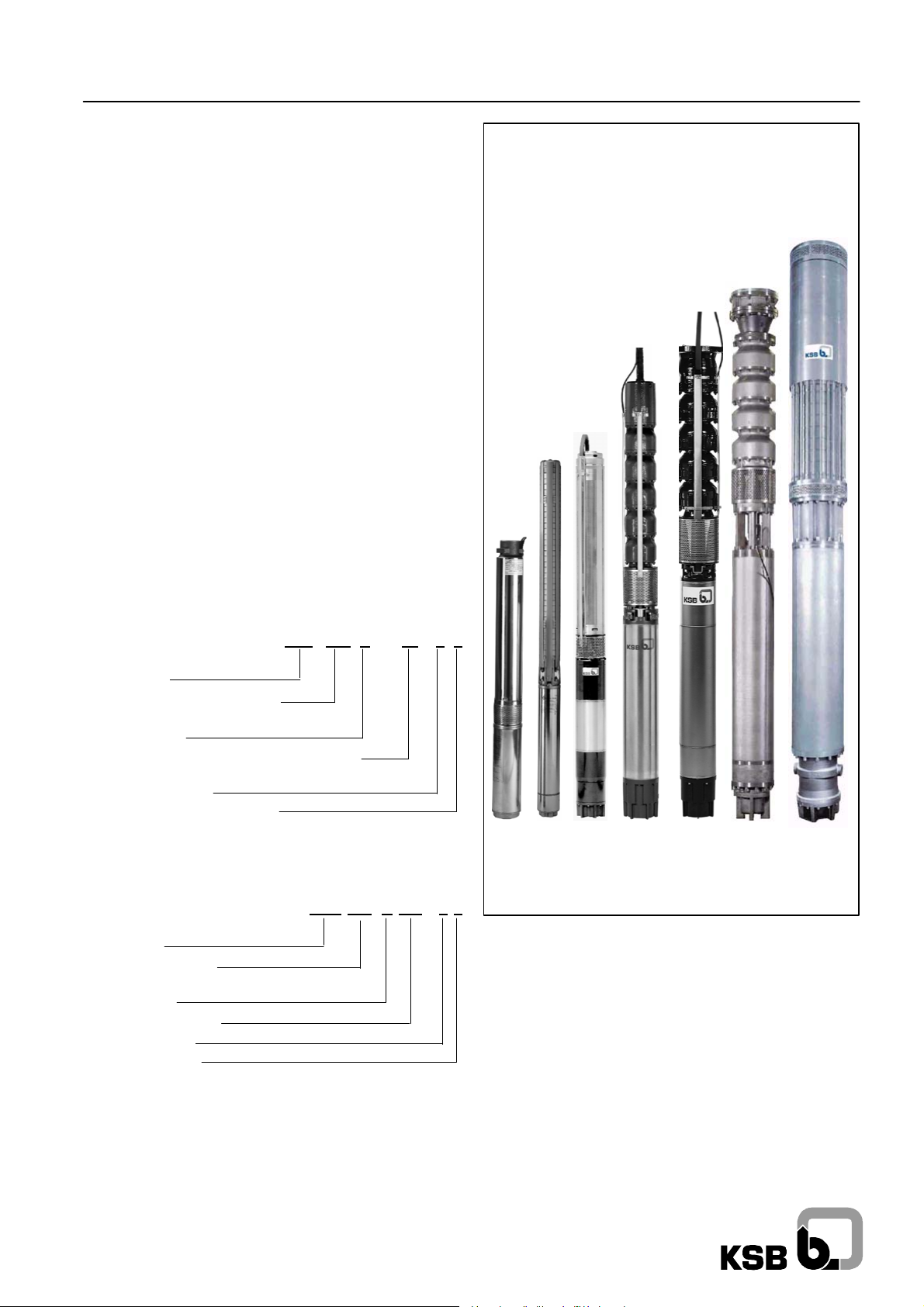
Submersible Borehole Pumps
S 100D, UPA 100C, UPA 150S, UPA 200,
UPA 200B, UPA 250C, UPA 300,
UPA 350, BSX -- BSF, UPZ
Pump Designation (Example)
UPA 200 B -- 8 0 /5 b
Type series
Minimum well diameter (mm)
(for ex.: 200 mm = 8 inches)
Design status
Capacity Q
Number of stages
Reduced impeller diameters
1)
UPA 200 -11 + 14: Q in l/s.
(m3/h)--(4upto10inches)
opt
(l/s) -- (12 inches and above)
Motor Designation (Example)
UMA 250 D 110 /21
Type series
Well diameter (mm)
(for ex. 250 mm = 10 inches)
Design status
Rated power P
Number of poles
Winding insulation
N
(kW)
Certification
Quality management certified to ISO 9001
1)
Available automation products:
• Hyamaster (UPA 150S -- UPA 350)
• hyatronic (UPA 150S -- UPA 350)
• switch gear (S 100D -- UPA 350)
Complete Range
The complete submersible borehole pump range comprises
pump models for flow rates up to Q = 2500 m
heads up to H = 1500 m.
The submersiblemotor range coverssizes for powerratings up
to P = 3500 kW and voltages up to U = 10,000 V for 50 and
60 Hz.
In addition, a special range is available which features
submersible motors with a higher number of poles.
3
/h (695 l/s) and
Page 2

50 Hz Submersible Borehole Pumps
Contents Page
The Submersible Borehole Pump Range 4.....................................
Operation with Soft Starters 5................................................
Operation with Frequency Inverter 6...........................................
Typical Installation Positions 7................................................
Submersible Borehole Pump Selection for Deep Wells 8............................
Request for Quotation (Form) 9...............................................
Head Losses in the Piping 10.................................................
Pump Sets 4 inches 11 + 23.................................................
Pump Sets 6 inches 33......................................................
Pump Sets 8 inches/10 inches 49.............................................
Pump Sets 12 inches/14 inches 69............................................
Pump Sets 16 inches and above 83 + 87......................................
Typical Tenders: 4 to 14 inches 91.............................................
Submersible Motors 96......................................................
Accessories 98.............................................................
Flow Velocity “v” Past the Motor 108...........................................
2
Page 3

Submersible Borehole Pumps50 Hz
What can you expect from the
“Submersible Borehole Pumps Booklet”?
The information provided can help you make a
-- quick
-- first rough selection
-- on your own
to find a suitable KSB submersible borehole pump for your
application. Wehave kept the volume of the catalogue down to
what we think is the absolute minimum. For the 4 to 14 inch
range, you will find the following information on the pump
selected:
-- pump series, size and number of stages,
-- motor series, size, power, amperage, and allowable
temperature,
-- starting method, supply voltage and type of installation,
-- material variants and
-- major dimensions and weights.
You may also complete, to the extent possible, the request for
quotation on page 9.
You will then receive as soon as possible a detailed quotation
and, if required, additional literature on KSB submersible
borehole pumps from the nearest KSB sales branch.
Benefits at a Glance
+ Full range of products
+ High-tech equipment
+ Optimum material selection
+ Maximum efficiency
+ Functional reliability
+ Long service life
+ No maintenance
+ “Clean” technology
+ Customer focus
General
Information on fields of application, available models, type of
installation, direction of rotation, coating, connection to power
supply and speed controlis provided inthe detailed sectionsfor
the relevant type series.
Pump Efficiency
The characteristic curves for UPA 200/200B and larger pumps
show pump efficiency for themaximum and optimum (reduced)
impeller diameter (for ex. ”c”). The efficiency of pumps with a
low number of stages or considerably reduced impeller
diameter (for ex. ”d”, “e”) is lower than the value shown; it is
given in the individual characteristic curves specifically
prepared for the quotation.
Dry Running Protection
For use in wells with marked water level fluctuations or
temporary low yield we strongly recommend installing dry
running protection equipment (”Accessories”).
Application Temperatures
The submersibleborehole pumps are, as a standard, suitablefor
use in water with temperatures of up to t = +30
indispensable requirementfor this isa flow velocityof v = 0.2 m/s
past the motor. This requirement is met, for example, when the
pump is installed in a deep well above the well screen / filter, etc.
With certain restrictions, some motor sizes may also be used
in water with temperaturesof up tot = +50
without an adequate cooling flow of water past the motor, i.e.
v = 0 m/s (for example, when the unit is installed in a deep well
below the screen / filter area or in a pump sump, etc.).
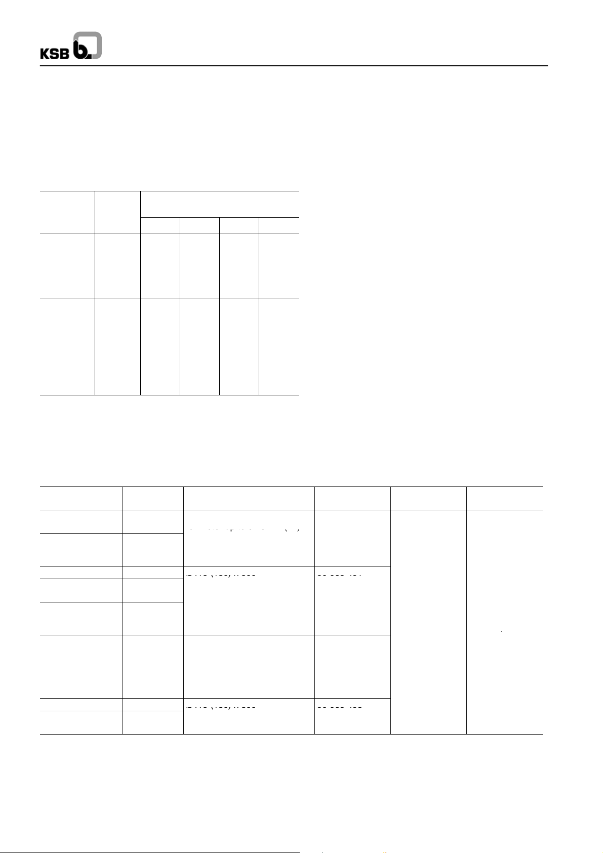
The details below provide data of adequate accuracy for the
allowable temperature as a function of the type of installation,
motor size and flow velocity v past the motor:
Vertical installation:
-- DN 100 / DN 150:
t
allow=tmax
-- UMA 150D/200D:
v= 0m/s t
v ≥ 0.2 m/s t
v ≥ 0.5 m/s t
-- UMA 250D:
v = 0 m/s Please consult manufacturer,......
v ≥ 0.2 m/s t
v ≥ 0.5 m/s t
1)
Values taken from tables on pages 15, 16 etc., 27, 28 etc..
1)
irrespective of flow past the motor.
≈ t
allow
allow
allow
allow
allow
max
=t
max
≈ t
max
=t
max
≈ t
max
o
C and for operation
1)
-- 5oC,......
1)
,.....
1)
+5oC......
1)
,.....
1)
,+5oC......
o
C. An
Horizontal installation:
The principle is the same as for vertical installation.
Exception: Pumps with UMA 250D motors.
These units must always be equipped with a flow inducer
sleeve. The flow inducer sleeve is not required, if the given
pump is equipped with a motor having a 10 % higher power
rating.
For all pump sets:
For a flow velocity of v ≥ 0.5 m/s and horizontalinstallation, check
back with the manufacturer.
3
Page 4
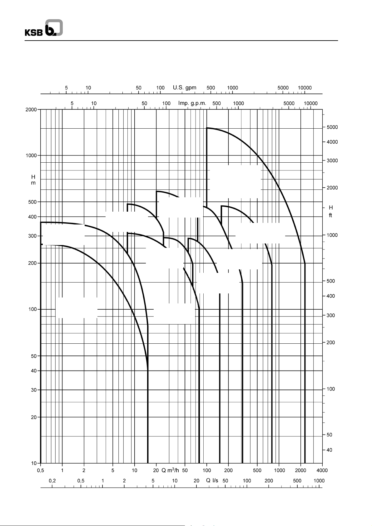
The Submersible Borehole Pump Range
" UPV 200
UPV 150S "
(6 inch)
" UPA 100C
(4 inch)
p. 23 -- 32
on request
50 Hz Submersible Borehole Pumps
" UPZ
BSX - BSF
(≥ 16 inch)
p. 83 -- 90
on request
(8 inch)
on request
" UPA 300, 350
(12/14 inch)
p. 69 -- 82
" S 100D
(4 inch)
p. 11 -- 22
UPA 200 "
(8/10 inch)
p. 49 -- 57
" UPA 150S
(6 inch)
p. 33 -- 48
" UPA 250C
(8/10 inch)
p. 62 -- 68
" UPA 200B
(8/10 inch)
p. 58 -- 61
4
Page 5
Submersible Borehole Pumps50 Hz
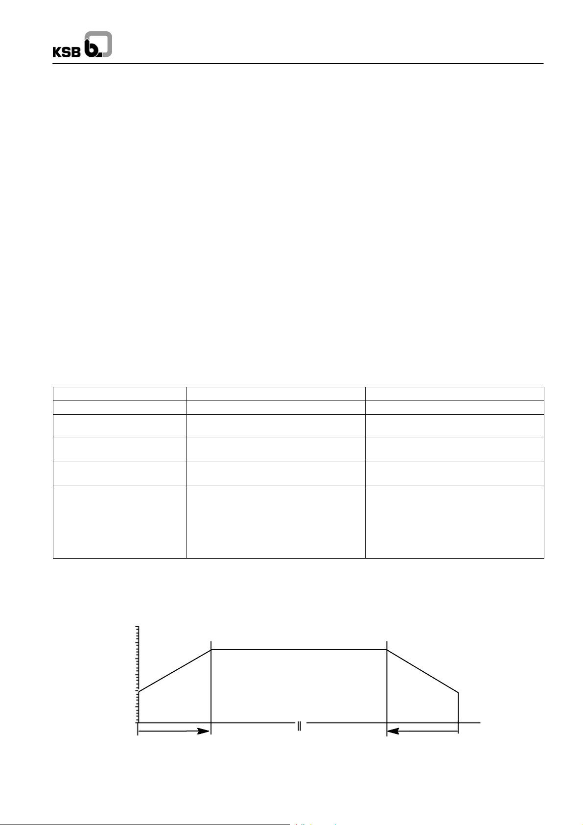
Operation of KSB submersible motor pumps with soft starters
Soft starterelectronically reduce the incoming line voltage and,
hence, the initial starting torque and starting current of electric
motors. During run--up they gently ramp up the applied voltage
to the motor.
In the case of submersible motors, the extremely slim design
and consequential small moments of inertia result in special
characteristics, which differ strongly from normal
asynchronous motors.
12.3 Soft starter settings
Effects on submersible borehole pumps
-- Starting current ⇒ approx. 40% to 65% of IArequired for
direct-starting.
-- Run-up time t
with approx. 0.2s to 0.5s for direct. starting.
-- Starting torque M
torque.
-- No current or torque peaks (I
switching arrangement.
-- Hydraulic pressure surges (waterhammer) upon starting
and stopping of the pump can be reduced, but not fully
eliminated. Therefore, soft starters are not suitable for
solving water hammer problems.
This would require the use of hydraulic control equipment
or a frequency inverter. To prevent effects due to power
failure, additional measures are required.
increased to approx. 1s to 3s compared
H
roughly 1/4 of the direct-starting
A
), as in star-delta
A,MA
Note
Conspicuous noiseor vibrations duringrun-up could well be an
indication of incorrect settings on the soft starter. This might be
due to exceeded ramp--up periods, incorrect operating mode
(setting), activated special functions, etc.
Parameter / Function Setting Comments
Minimum starting voltage 40% of the motors’ rated voltage
Ramp time / acceleration
(run--up) time
Current limitation IA/INpreset to approx. 3.5 Should only be altered with allowance for
Deceleration (run--down) time /
stop ramp
Special functions, e.g.:
-- special “pump function”
-- kick--start / boost function
-- speed adjustment
-- Current contoller
-- cos ϕ- / economy function
-- delayed starting
During operation the soft starter must be bridged (bypass). This helps to avoid losses at the machine and motor to secure proper
permanent operation.
120
< 4s Ramp time is nor identical with the motor
Deceleration time tA< 4s Better without a ramp.
OFF Do not use, as they tend to be troublesome,
Run--up
Operation
actual run--up time
< 4s
t
H
particulary in submersible borehole applications.
Run--down
100
80
60
40
Voltage [%]
20
0
4s
Time [s]
4s
5
Page 6

Pump Operation with Frequency Inverter
3
0
203
0
50 Hz Submersible Borehole Pumps
In principle, the motors of submersible borehole pumps can
also be run on a frequency inverter. As submersible motors
differ from conventional standardized motors in terms of
bearings, moment of inertia, insulation, temperature increase,
loss distributionand heat distribution, the following parameters
must be observed:
-- Maximum allowable acceleration time (start ramp)
-- Maximum allowable deceleration time (stop ramp)
-- Minimum frequency
-- Maximum operating frequency
-- Maximum permissible voltage increase velocity and peak
voltages
-- Control principle of frequency inverter
Maximum Allowable Acceleration Time (Start
Ramp) and Deceleration Time (Stop Ramp)
The plain bearings of the submersible motor do not tolerate
operation below the minimum frequency f
mixed lubrication range).
For this reason, the acceleration period from standstill to
minimum frequency f
should not exceed 2s. The same
min
applies to the deceleration period.
(operation in
min
Minimum Frequency
Minimum frequency f
Motor size
DN 100
Vertical
installation
30
DN 150
UMA 150D
20 30
UMA 200D
UMA 250D
UMA 300D /2
UMA 300D /4 30 35
(Hz)
min
Horizontal
installation
30
-- --
Maximum Operating Frequency
Frequency inverter operation above the nominal frequency
(50Hz /60Hz) ofthe pumpunit must beavoided soas toprevent
motor overload.
Maximum Permissible Voltage Increase Velocity
and Peak Voltages
Excessive voltage increase velocities and excessive peak
voltages will reduce the service life of the winding insulation.
For this reason, the following limits must be adhered to:
-- Maximum voltage increase velocity:
du/dt ≤ 500 V/µs
-- Maximum peak voltages to earth:
Low-voltage motors ≤ 1 kV: J1 insulation ≤ 600 V
J2 insulation ≤ 800 V
For motor sizes DN 100 and DN 150, the limit values for J1
insulation apply.
Note: Compliance with these limits can usually be assured by
means of a sine filter or
du
/dtfilter.
Control Principle of Frequency Inverter
The control principleof the frequency inverter must correspond
to linear U/f curve control. If other control principles are
employed, such as field-oriented inverters, inverters with DTC
or NOF,the manufacturerof the frequency invertermust ensure
that thespecial requirementsof submersiblemotors (very small
moment of inertia, electrical data) are taken into account.
Note: For details refer to ”Design and Selection Information for
Running Submersible Borehole Pumps on Frequency
Inverters”, Ref. No. 3400.0610--10.
6
Page 7
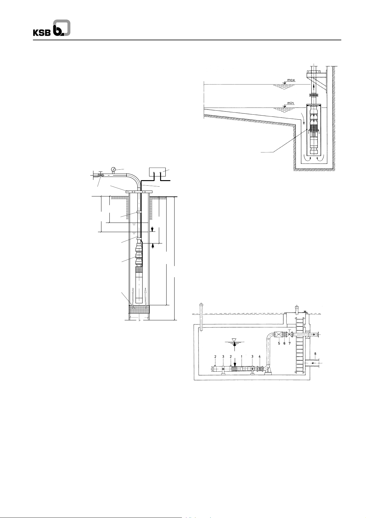
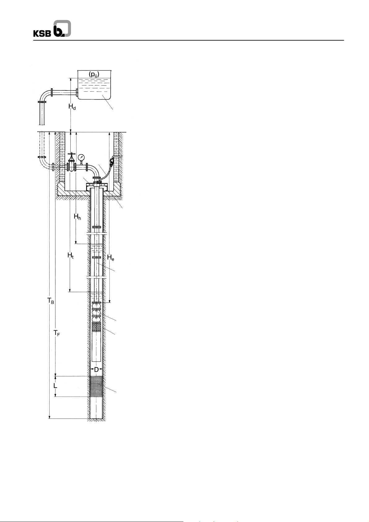
Typical Installation Positions
a) Vertical Installation
(deep well, pump sump, etc.)
CAUTION:
The construction of the well head must meet the relevant
regulations ofthe competent authorities! The unit must never
be installed with its suction strainer exactly at the level of the
well screen / filter!
Before installingthe unitin narrowdeep wells werecommend to
check narrow boreholes for dimensional accuracy over their
entire length, e.g. by inserting a pipe of the length and biggest
outside diameter of the pump unit. Sharp bends or bottlenecks
can make installation difficult or even impossible.
The unit is supported on the well head by supporting clamps
(low-weight unitsand lowsubmergence) ora supportingflange.
The construction of the well head must meet the relevant
regulations of the competent authority.
5
8
Submersible Borehole Pumps50 Hz
Cooling / Suction shroud
Fig. 2 Installation in a pump sump
3400:50
4
6
H
h
H
t
3
B
B
7
H
e
X
2
T
1
1 Submersible borehole pump
F
T
B
2 Riser pipe
3 Cable tie
9
4 Supporting flange / Well head
5 Pressure gauge
6 Shut-off valve
7 Power supply cable
8 Control box
9 Well screen / filter
D
3410:70/4
D = Inside well diameter
T
= Well depth
B
= Well screen / filter depth
T
F
H
= Installation depth
e
H
= Static water level
h
= Dynamic water level (Pumping water level)
H
t
Fig. 1 Vertical installation (in deep well, pump sump, etc.)
The suspension arrangement of the pump unit must be
designed and dimensionedso that allstatic anddynamic forces
can be absorbed and that theriser pipe cannot slip downwards.
The supporting clamps or flanges must be fastened at the well
head so that they cannot shift of lift off the well head.
The unit mustnever be installed with its suction strainer exactly
at the level of the well screen / filter! Excessive flow in the area
of the well screen / filter entails the risk of large amounts of
entrained sand clogging the well screen / filter and causing
excessive wear in the pump.
Pump units installed in a pump sump must generally be
equipped with a cooling or suction shroud (fig. 2).
b) Horizontal Installation
(in reservoirs, mine shafts, etc.)
CAUTION:
The instructions given in ”a) Vertical installation” shall also apply
by analogy to horizontal installation, when the pump unit is fitted
on mounts (pedestals / supporting frame) supplied by us. If the
pump and motor are supplied ready mounted on a supporting
frame, on-site alignment of pump and motor will not be
necessary. If this is not the case, the relevant installation /
assembly drawing must be ordered, giving the following details:
-- installation height (floor clearance),
-- spacing of supports,
-- submergence X
The ground / foundation must be level and of sufficient
load-bearing capacity to accept the weight of the unit with
supports.
Air intake from an inlet arranged above the water level is not
permitted.
X
3410:71/2
Fig. 3 Horizontal installation (in tanks, mine shafts etc.)
1 Submersible borehole pump
2 Water storage tanks (UMA 300D and 14D motors only)
3 Pedestal
4 Expansion joint
5 Check valve
(only if pump unit does not have its own check valve)
6 Dismantling joint
7 Shut-off valve
8 Intake
7
Page 8
50 Hz Submersible Borehole Pumps
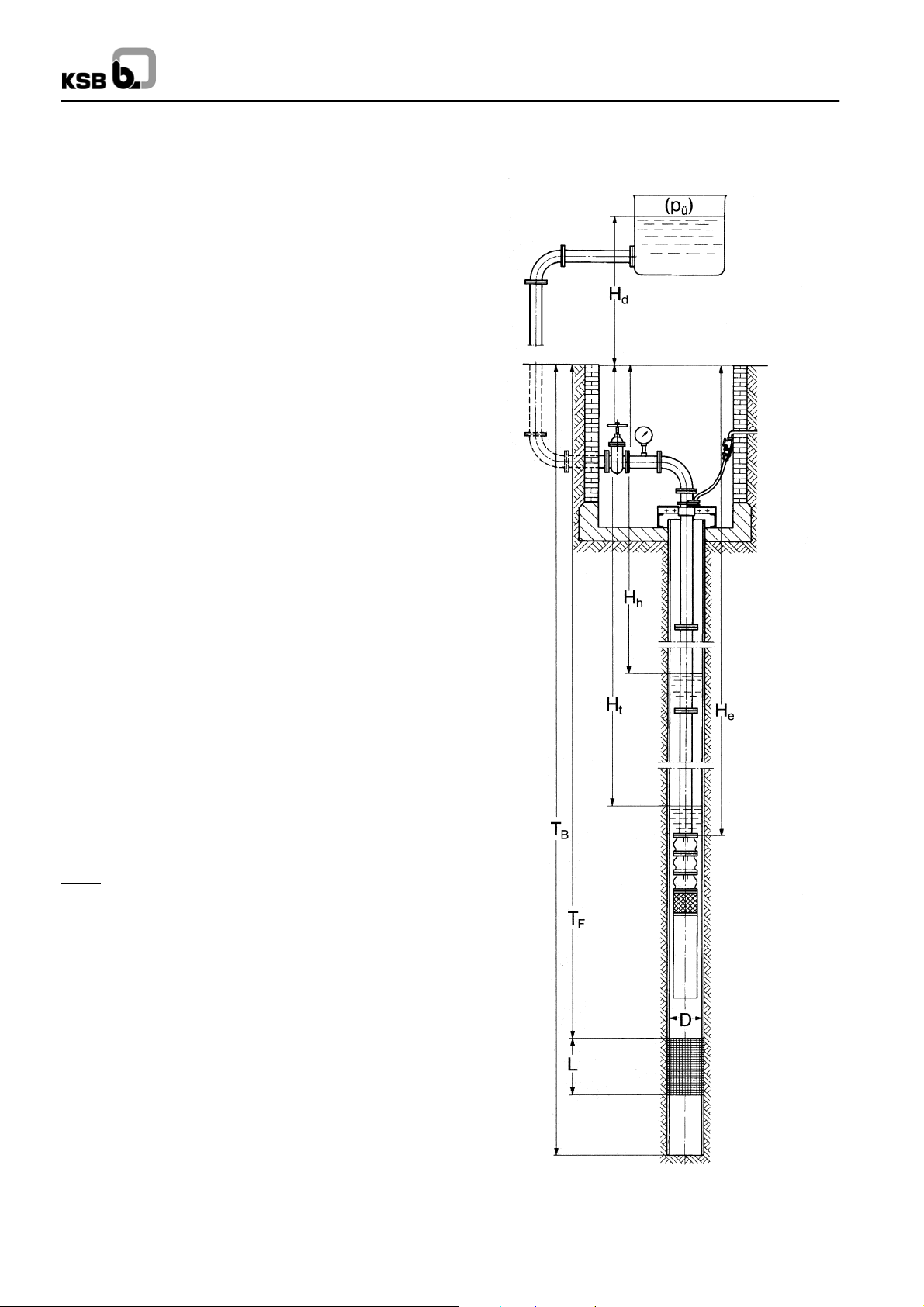
Submersible Borehole Pump Selection for Deep Wells
Pump Selection
The following data are required for a first rough selection of a
submersible borehole pump:
-- Capacity Q in m
-- Pressure at well head H
-- Well diameter in inches or mm
-- Temperature of fluid handled t
-- Pump head HPin m
While Q, H
head H
A
to be developed by the pump needs to be calculated.
P
There are two typical applications to be considered (see the
drawing on the right):
1. Pumping into an open overhead tank
HP=HA+Ht+Hv+HS[m]
where ...
HA= Required pressure at well head
H
= Lowest water level (dynamic water level)
t
Hv= Head losses in the checkvalve (see characteristic
H
= Head losses in riser pipe up to well head
S
H
= Installation depth
e
3
/h (l/s)
in m
A
in °C
A
, D and tAare usually specified bythe customer,the
curves for different stage numbers for UPA 150S
and above).
(see page 10).
2. Pumping into a closed tank
Hp=HA+Ht+Hv+HS+pü[m]
where ...
pü= Gauge pressure (also air cushion) in a tank
Example
Given ...
QA= 120 m3/h,
=95m,
H
A
tA=+15°C,
50 Hz, 400 V and d.o.l. starting,
well diameter D = 250 mm (10 inches).
...
Found
1. step:
pump type UPA 200B/250C
(for Q
2. step:
pump size UPA 200B - 130
(for QAtaken from selection chart on page 50)
3. step:
pump set UPA 200B-130/6b + UMA 200D 45/21
(for Hp=HA+Ht+HV+HS= 95 + 4 + 0.75 + 0.26 = 100 m
with H
numbers on page 61).
Pump efficiency: ηP= 80.5 % (without check valve)
taken from selection chart on page 4)
A
taken from characteristic curves for different stage
V
3300:54/3
Figure:
Deep well with submersible borehole pump and overhead tank
or closedtank at apressure above atmospheric pressureof p
ü.
8
Page 9
50 Hz Submersible Borehole Pumps
Request for Quotation
We should like to test the efficiency and quality of your computer-aided quotation process.
Please let us have a quotation based on the following data. (Fill in the required data and
/ or underline the relevant information, as far as available.)
1. Water quality
Discharge head required at theend of the
piping:
Temperature °C.....................
8
Sand content g/m
..................
H = m ( bar)............. ........
3
Cut-out pressure in the pressure vessel:
Please attach water analysis, if available.
p
= bar............
Ü
2. Type of system
7
6
Well / Mine shaft / Tank
Free discharge above ground
Discharge into an overhead tank
Discharge into a pressure vessel
c)Piping outside well head housing:
Overall length m....................
Nominal diameter mm...............
Number of bends, valves and fittings:
pcs................................
3. Deep well
Well depth(distance from ground level to
5
well base):
T
=m............................
B
Inside diameter at submersible pump
installation depth:
D = mm ( inches).............. ....
4
Well screen / filter:
-- Installation depth T
=m...........
F
Inside diameter reduced by incrustation
to: D = mm........................
6. Installation depth
Ground level to check valve / to
connection branch:
He = m............
Caution: Do not install the submersible
borehole pump at the level of the well
screen / filter!
F
1 Well screen / filter
2 Well casing
3 Submersible borehole pump
4 Riser
5 Well head housing
6 Well head
7 Power supply cable
8 Overhead tank
3
2
1
3300:54/3
-- Length L
=m...................
F
4. Capacity
Q= m3/h ( l/s)............. .......
5. Total head
(including all friction losses)
H= m............................
If H is not known, please provide the
following data:
a)
Water level in well, measured from
ground level:
-- Static water level: H
-- Dynamic water level: H
(at capacity Q = m
b)
Head above ground:
Geodetic altitude up to the highest point
of the pipeline or up to the highest water
level in the overhead tank:
H
=m...........................
d
=m..........
h
=m........
t
3
/h)..............
7. Power supply
Single- / three-phase alternating current.
Mains voltage at well:
U= V.............................
Frequency f = Hz..................
If voltage drops cannot be precluded:
Minimum voltage ...
U
=V...........
min
8. Control box
Manual start-up / remote control / automatic start-up by way of float switch,
pressure switch or dry running protection
equipment.
Other types of switchgear: ...........
...................................
9. Starting method
D.o.l. (without / with autotransformer or
soft starter) or star-delta starting.
9
Page 10
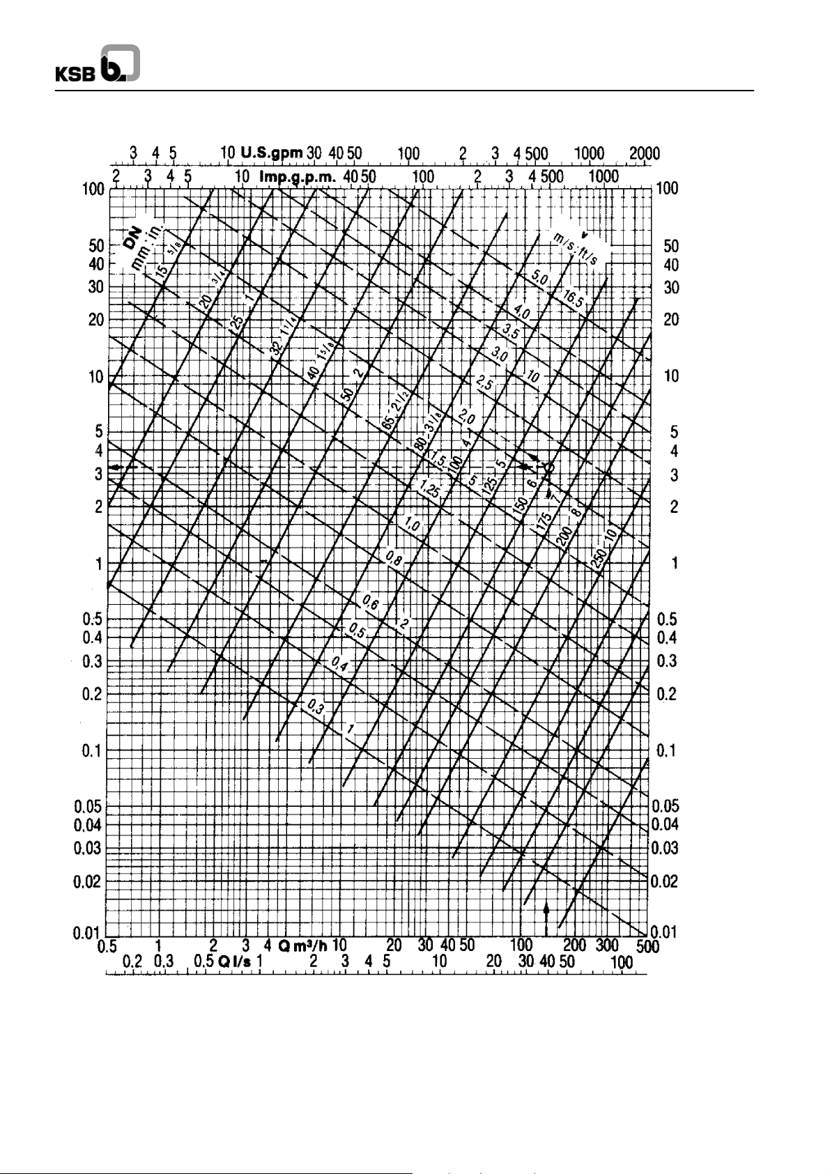
Head losses in the piping
H
V
m/100 m
50 Hz Submersible Borehole Pumps
H
V
ft/100 ft
The frictionlosses givenin theabove chart roughlyapply tonew
cast iron pipes.For newrolled steelor plasticpipes, multiply the
values by approx. 0.8. For old, slightly rusty cast iron pipes,
multiply by approx. 1.25. In pipes with incrustations, friction
losses may rise to 1.7 times the value given in the chart for the
10
3300:103/3-2
diameter reduced by incrustations. For pipes subject to considerable incrustation, the friction losses can only be determined experimentally.
Example: Q = 140 m
H
V
3
/h, new DN 150 cast iron pipe.
= 3.25 m per 100 m of pipe, v = 2.2 m/sec.
Page 11
50 Hz S 100D
Applications
-- Domestic and general water supply
-- Irrigation and spray irrigation
-- Lowering groundwater levels
-- Fountains
-- Pressure boosting
-- Air-conditioning systems
-- Fire protection
-- Cooling water cycles
Operating Data
Caoacity Q up to 16 m3/h
Head H up to 300 m
Temperature of fluid handled
tupto+30°C in continuous operation
Power Pn up to 5.5 kW
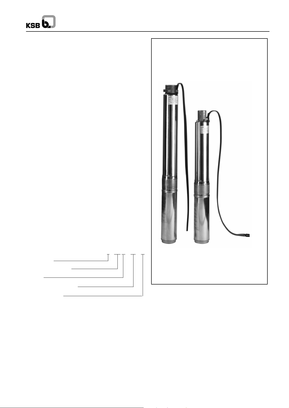
Pump Type / Design
Pump:
Stainless steel and plastic multistage centrifugal pump.
-- Additional bearing depending on the number of stages
-- Pump sizes D1 and D2 with anti-blockage feature. This consists of a hexagonal polyurethane disc mounted to the back
of the diffuser. A PE-HD ring fitted to the impeller front side
sits closeto thedisc. The impeller hub is protected by apolyurethane ring.This design improves the starting torque of lowcapacity pumps and has the effect that solid particles such as
sand are propelled outside instead of clogging the pump.
Motor:
Submersible canned motor (Franklin), NEMA standard, 50 Hz
-- For single-phase alternating current (type PSC) or threephase current
-- With short cable
-- Connection to power supply mains by means of cable connector (accessories)
-- D.o.l. starting, start-up frequency up to 20/h
-- Type of enclosure IP 68
-- Thermal class B
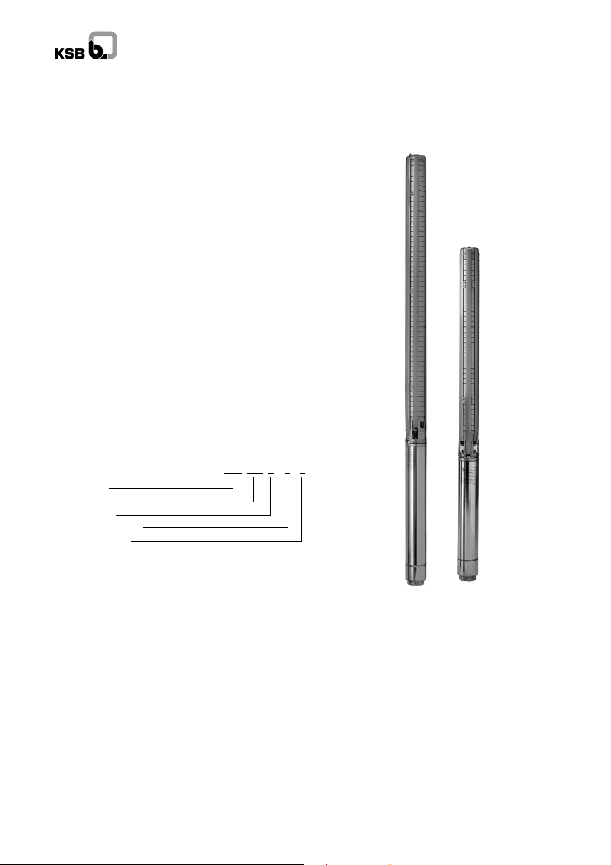
Submersible Borehole Pumps
for Well Diameters
of 100 mm (4 inch)
Designation
S 100 D -- 4 / 6
Type series
Well diameter (mm)
Status
Capacity (m
Number of stages
3
/h)
Recommended Accessories
UPA Control: Control box for motor and dry running protection
by immersion electrodes.
Automatic control unit: in conjunction with the Controlmatic
E or Cervomatic EDP control and monitoring units, which protect thepump againstdry running, ifthe waterlevel falls,S 100D
can be used for automatic water supply
Certification
Quality management certified to ISO 9001
Available automation products:
• Automatic control unit
Product Features
-- Pumps sizes D1 and D2 with anti-blockage feature
-- Rust-proof
-- Suitable for installation in narrow deep wells
-- High efficiency
-- Hermetically sealed motor
-- Motor designed for maximum pump output
-- Low noise level
-- For vertical, angled or horizontal installation
-- Check valve with anti-blockage valve disc
11
Page 12
50 Hz S 100D
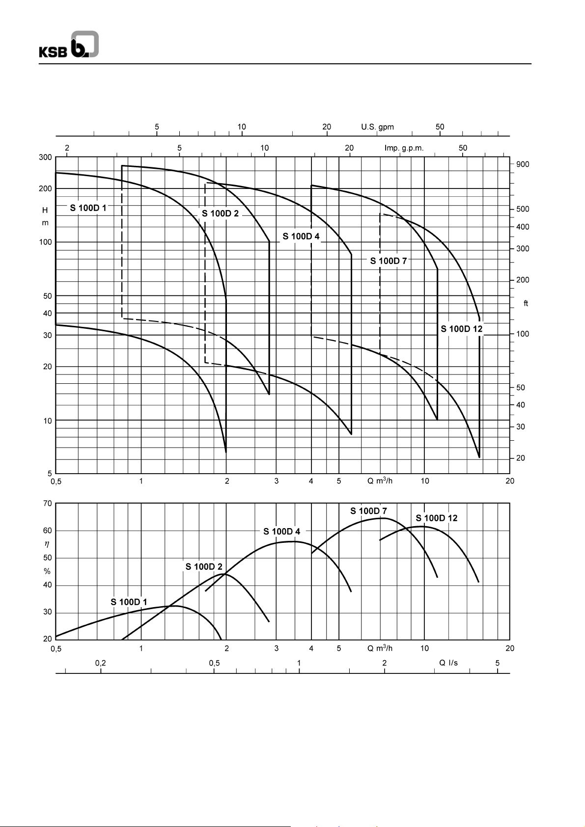
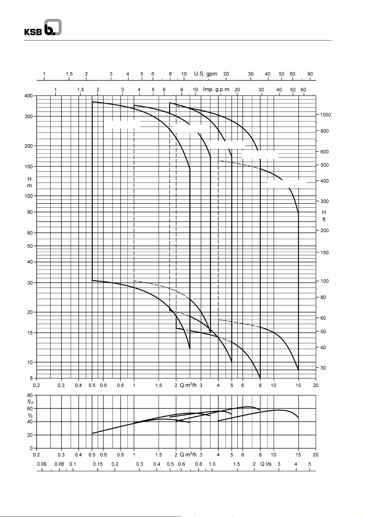
Selection Chart (Ranges on Offer) n ≈ 2900 rpm
Note:
Up to a motor rating of PN= 2.2 kW, all pump sizes can be supplied with either single-phase a.c. or three-phase current motors.
12
Page 13
50 Hz S 100D
Materials
Component
Pump ...
Outer pump casing/
Suction casing /
Valve housing
Stage casing CrNi steel (1.4301)
Stage casing (diffuser) /
Impeller
Shaft Cr-steel (1.4021)
Bearing bush Nitril NBR 80
Screws, bolts and nuts CrNiMo-steel (A4--70)
Motor ...
Shaft CrNi steel (1.4305)
Bearing carrier CrNi steel (1.4301)
Stator case CrNi steel (1.4301)
G (Standard design)
CrNi steel (1.4301)
glass fibre reinforced Noryl
(PPO)
Bearings / Lubrication
Plain bearings, lubricated by the fluid pumped or by the motor
fill liquid. Depending on the number of stages, an additional intermediate bearing is provided in the pump.
The axial thrust is balanced by a thrust bearing in the motor.
The hydraulic thrust is balanced by the pump’s counter thrust
bearing.
Direction of Rotation of the Pump
Clockwise rotation (viewed at the drive shaft end).
Pump End (Discharge Nozzle)
S 100D - 1, 2, 4 + 7: Internal thread G 1’’1/4(DN 32).
S 100D - 12: Internal thread G 2’’ (DN 50).
Drive
Type canned motor in squirrel-....................
cage design, 2 poles
Connection NEMA standard..............
Type of enclosure IP 68........
Frequency 50 Hz..............
Type of current single-phase a.c. (1
or three-phase (3
Rated voltage U 220 ... 230 V (1~) and..........
380 ... 400 V (3~)
Rated power P
Voltage fluctuation up to ± 5 % acc. to VDE........
Frequency of starts up to 20/h.......
Min. delay before restarting 3 min.
A starter for single-phase a.c. motors in PSC design (with
integrated run capacitor and motorprotection) is included inthe
scope of supply.
N
up to 2.2 kW for 1~ and............
up to 5.5 kW for 3~
µ)...........
µ)
Connection to Power Supply
All DN 100 motors are factory-equipped as follows:
1 x 1.5 mflatcable, quality 4x 1.5 mm2(3 phases + 1 earthconductor).
Exception: DN 100 motors with a rating of 5.5 kW, 3~, are
equipped as follows: 2.5 m cable, quality 4 x 1.5 mm
Connection of extensioncable (any length)by meansof a cable
connector
Connected at the factory by means of a standard cable con-
nector (non-separable, shrink tube)
Ident. No. 40 980 708
For cable quality 4 x 1.5 mm
Ident. No. 39 020 536
For cable quality 4 x 4 mm
Connected at the factory with Franklin cable connector
(separable, sealing compound)
Ident. No. 90 049 385
For cable quality 4 x 1.5 mm
2
or 4 x 2.5 mm
2
2
up to 4 x 2.5 mm
2
.
2
2
Installation
Vertical and, depending on the number of stages, also angled
and horizontal installation.
Starting Mode
Only direct on line.
Temperatures
The S 100D submersible borehole pump is designed for use in
water with temperatures of up to t = + 30
o
C.
Variants Available on Request
-- Higher fluid temperatures
-- Higher voltages up to 500 V
-- Other frequencies
13
Page 14
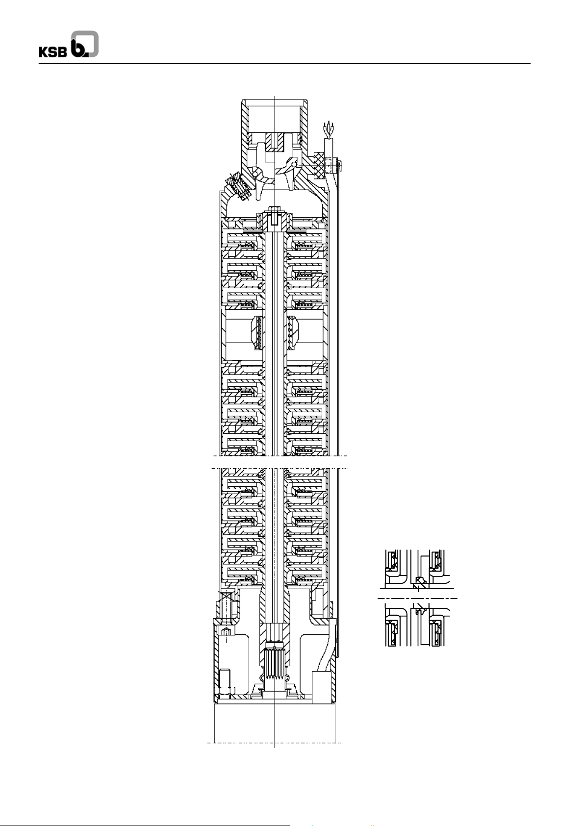
Design Features
50 Hz S 100D
Easy to commission and service
D Vent valve for operation with automatic
control units such as Controlmatic E or
Cervomatic EDP
D Easy to install thanks to plug--type
connection of power cable of Franklin
submersible motor
D The cable guard is easy to fit and remove.
High operating reliability and
long service life
D Maintenance--free and wear--protected
pump bearings
D Special guide feature prevents jamming
or tilting of the check valve
D Cable guard protects cables from damage.
Highly corrosion--resistant
D Suction casing, check valve
housing and outer casing made of
stainless steel
D Hydraulic system made of glass
fibre reinforced Noryl
14
Page 15
S 100D -- 1 ...
(motor)
ith
for well diameters of 100 mm (4 inch)
Pumps with submersible motors for ...
-- Temperature of fluid handled up to + 30oC............
-- Current / Operating voltage 1~/230 V..................
or 3~/400 V.......................................
-- Starting direct......................................
50 Hz S 100D
Rated
power
Current intensity for
...
Installa-
2)
tion
Oper-
ation
w
control
unit
3
Pump unit
S 100D
P
kW
1~
230 V
1)
N
I
N
A
3~
400 V
I
N
A
1/ 7 0.37 3.4 1.3 v+h x
1/ 9 0.37 3.4 1.3 v+h x
1/12 0.55 3.4 1.3 v+h x
1/14 0.55 4.3 1.7 v+h x
1/16 0.55 4.3 1.7 v+h x
1/20 0.75 4.3 1.7 v+h x
1/25 1.10 5.7 2.2 v x
1/30 1.10 5.7 2.2 v x
1/35 1.50 8.6 3.2 v x
1/40 1.50 8.6 3.2 v x
1/50 2.20 10.6 4.0 v x
1)
Capacitor run motors (PSC motors) with starter.
2)
v = vertical and h = inclined / horizontal.
3)
Always check and make sure that the operating pressure of Controlmatic /
Cervomatic units is not exceeded.
4)
3~ only
3)4)
Note : Use a cooling shroud for horizontal installation.
)
3)
3)
3)
3)
3)
3)
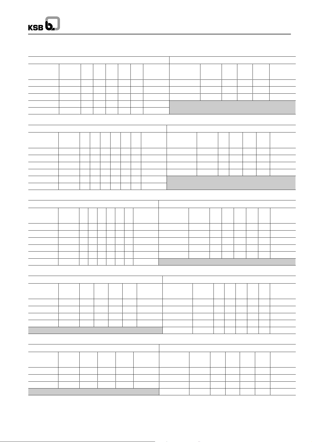
Capacity
Dimensions / Weights / Ident. Numbers / Horizontal Installation
1~/ 230 V 3~/ 400 V
Pump unit
S 100D
1/ 7
1/ 9
1/ 12
1/ 14
1/ 16
1/ 20
1/ 25
1/ 30
1/ 35
1/ 40
1/ 50
For information on cooling shroud refer to page 20.
L
A
≈ mm
575
625
720
795
810
925
1100
1210
1395
1505
1805
m
≈ kg
11. 5
11.7
13.4
13.6
13.8
14.3
16.3
16.8
20.0
20.6
22.7
A
Ident No. A
39 022 528
39 022 529
39 022 530
39 022 531
39 022 532
39 022 533
39 022 534
39 022 535
39 022 536
39 022 537
39 022 538
≈ mm
371
425
508
552
597
687
-- -- -- --
-- -- -- --
-- -- -- --
-- -- -- --
-- -- -- --
L
A
≈ mm
555
605
700
755
780
870
1045
1150
1310
1450
1705
m
≈ kg
10.7
10.9
12.2
12.4
12.6
13.1
14.9
15.4
17.4
18.0
20.3
A
Ident No. A
39 022 565
39 022 566
39 022 567
39 022 568
39 022 569
39 022 570
39 022 571
39 022 572
39 022 573
39 022 574
39 022 575
≈ mm
362
416
492
537
582
672
-- -- -- --
-- -- -- --
-- -- -- --
-- -- -- --
-- -- -- --
C
G1”1/4
Accessories: UPA Control for dry running protection using 1 or 3 immersion electrodes, see page 21.
15
Page 16
S 100D -- 2 ...
p
for well diameters of 100 mm (4 inch)
50 Hz S 100D
Pumps with submersible motors for ...
-- Temperature of fluid handled up to + 30
-- Current / Operation voltage 1~/230 V..................
or. 3~/400 V......................................
-- Starting direct......................................
Pump unit
S 100D
Rated
power
(motor)
P
kW
N
Current intensity
for ...
1~
230 V
I
N
A
1)
3~
400 V
I
N
A
Instal-
lation
2)
Opera-
tion with
control
unit
3
2/ 7 0.37 3.4 1.3 v+h x
2/11 0.55 4.3 1.7 v+h x
2/15 0.75 5.6 2.2 v+h x
2/18 1.1 8.6 3.2 v+h x
2/20 1.1 8.6 3.2 v+h x
2/22 1.1 8.6 3.2 v+h x
2/27 1.5 10.6 4.0 v+h x
2/30 1.5 10.6 4.0 v x
2/33 2.2 15.5 5.9 v x
2/38 2.2 15.5 5.9 v x
2/44 2.2 15.5 5.9 v x
2/50 3.0 -- 7.8 v x
1)
Capacitor run motors (PSC motors) with starter.
2)
v = vertical and h = inclined / horizontal.
3)
Always check and make sure that the operating pressure of Controlmatic /
Cervomatic units is not exceeded.
4)
3~ only
3)
3)
3)
3)
3)
3)
3)
3)
3)4)
Note : Use a cooling shroud for horizontal installation.
o
C............
)
Capacity
Dimensions / Weights / Ident. Numbers / Horizontal Installation
1~/ 230 V 3~/ 400 V
Pump unit
S 100D
2/ 7
2/11
2/15
2/18
2/20
2/22
2/27
2/30
2/33
2/38
2/44
2/50
For information on cooling shroud refer to page 20.
L
A
≈ mm
570
695
815
940
985
1030
1175
1235
1425
1535
1670
-- -- -- -- --
m
A
≈ kg
11. 3
13.0
14.8
17.7
17.8
18.0
19.5
19.9
23.6
24.1
24.6
-- -- -- -- --
Ident No. A
39 022 539
39 022 540
39 022 541
39 022 542
39 022 543
39 022 544
39 022 545
39 022 546
39 022 547
39 022 548
39 022 549
-- -- -- -- --
≈ mm
371
484
589
684
729
775
901
-- -- -- --
-- -- -- --
-- -- -- --
-- -- -- --
-- -- -- --
L
A
≈ mm
550
665
790
880
925
970
1120
1180
1325
1435
1570
1770
m
≈ kg
10.5
11.8
13.4
15.1
15.2
15.4
17.1
17.5
19.0
19.5
20.0
23.6
A
Ident No. A
39 022 576
39 022 577
39 022 578
39 022 579
39 022 580
39 022 581
39 022 582
39 022 583
39 022 584
39 022 585
39 022 586
39 022 587
≈ mm
362
470
574
655
701
746
873
-- -- -- --
-- -- -- --
-- -- -- --
-- -- -- --
-- -- -- --
C
G1”1/4
Accessories: UPA Control for dry running protection using 1 or 3 immersion electrodes, see page 21.
16
Page 17
S 100D -- 4 ...
p
for well diameters of 100 mm (4 inch)
50 Hz S 100D
Pumps with submersible motors for ...
-- Temperature of fluid handled up to + 30
-- Current / Operating voltage 1~/230 V..................
or 3~/400 V......................................
-- Starting direct......................................
Pump unit
S 100D
Rated
power
(motor)
P
kW
N
Current intensity
for ...
1~
230 V
I
N
A
1)
3~
400 V
I
N
A
Instal-
lation
2)
Opera-
tion with
control
unit
3)
4/ 3 0.37 3.4 1.3 v+h x
4/ 6 0.55 4.3 1.7 v+h x
4/ 8 0.75 5.7 2.2 v+h x
4/11 1.10 8.6 3.2 v+h x
4/16 1.50 10.6 4.0 v+h x
4/21 2.20 15.5 5.9 v+h x
4/24 2.20 15.5 5.9 v x
4/33 3.00 -- -- -- 7.8 v x
4/40 3.70 -- -- -- 9.1 v x
1)
Capacitor run motors (PSC motors) with starter.
2)
v = vertical and h = inclined / horizontal.
3)
Always check and make sure that the operating pressure of Controlmatic /
Cervomatic units is not exceeded.
4)
3~ only
3)4)
3)4)
3)4)
3)4)
3)4)
Note : Use a cooling shroud for horizontal installation.
o
C............
Capacity
Dimensions / Weights / Ident. Numbers / Horizontal Installation
1~ / 230 V 3~ / 400 V
Pump unit
S 100D
4/ 3
4/ 6
4/ 8
4/11
4/16
4/21
4/24
4/33
4/40
For information on cooling shroud refer to page 20.
L
A
≈ mm
505
610
690
820
975
1180
1255
-- -- -- --
-- -- -- --
m
≈ kg
11. 5
13.4
15.1
18.2
20.1
24.8
25.3
-- -- -- --
-- -- -- --
A
Ident No. A
39 022 550
39 022 551
39 022 552
39 022 553
39 022 554
39 022 555
39 022 556
-- -- -- -- --
-- -- -- -- --
≈ mm
333
399
489
594
734
900
-- -- -- --
-- -- -- --
-- -- -- --
L
A
≈ mm
485
580
665
760
920
1080
1155
1595
1805
m
≈ kg
10.7
12.2
13.7
15.6
17.7
20.2
20.7
25.5
33.0
A
Ident No. A
39 022 588
39 022 589
39 022 590
39 022 591
39 022 592
39 022 593
39 022 594
39 022 595
39 022 596
≈ mm
324
384
475
566
706
847
-- -- -- --
-- -- -- --
-- -- -- --
C
G1”1/4
Accessories: UPA Control for dry running protection using 1 or 3 immersion electrodes, see page 21.
17
Page 18
S 100D -- 7 ...
p
for well diameters of 100 mm (4 inch)
50 Hz S 100D
Pumps with submersible motors for ...
-- Temperature of fluid handled up to + 30
-- Current / Operating voltage 1~/230 V..................
or 3~/400 V.......................................
-- Starting direct......................................
Pump unit
S 100D
Rated
power
(motor)
P
kW
N
Current intensity
for ...
1~
230 V
I
N
A
1)
3~
400 V
I
N
A
Instal-
lation
2)
Opera-
tion with
control
unit
3)
7/ 4 0.75 5.7 2.2 v+h x
7/ 6 1.10 8.6 3.2 v+h x
7/ 8 1.50 10.6 4.0 v+h x
7/11 2.20 15.5 5.9 v+h x
7/13 2.20 15.5 5.9 v+h x
7/18 3.00 -- -- -- 7.8 v+h x
7/23 3.70 -- -- -- 9.1 v x
7/28 5.50 -- -- -- 13.7 v x
7/33 5.50 -- -- -- 13.7 v x
1)
Capacitor run motors (PSC motors) with starter.
2)
v = vertical and h = inclined / horizontal.
3)
Always check and make sure that the operating pressure of Controlmatic /
Cervomatic units is not exceeded.
4)
3~ only
4)
4)
4)
3)4)
3)4)
3)4)
3)4)
Note : Use a cooling shroud for horizontal installation.
o
C............
Capacity
Dimensions / Weights / Ident. Numbers / Horizontal Installation
1~ / 230 V 3~ / 400 V
Pump unit
S 100D
7/ 4
7/ 6
7/ 8
7/11
7/13
7/18
7/23
7/28
7/33
For information on cooling shroud refer to page 20.
L
A
≈ mm
611
736
831
1011
1076
-- -- -- --
-- -- -- --
-- -- -- --
-- -- -- --
m
≈ kg
14.6
17.7
19.1
23.1
23.6
-- -- -- --
-- -- -- --
-- -- -- --
-- -- -- --
A
39 022 557
39 022 558
39 022 559
39 022 560
39 022 561
Ident No. A
≈ mm
421
517
599
740
808
-- -- -- -- --
-- -- -- -- --
-- -- -- -- --
-- -- -- -- --
-- -- -- --
-- -- -- --
-- -- -- --
-- -- -- --
L
A
≈ mm
586
676
776
911
976
1211
1516
1881
2051
m
≈ kg
13.2
15.1
16.7
18.5
19.0
23.1
30.8
38.3
39.4
A
Ident No. A
39 022 597
39 022 598
39 022 599
39 022 600
39 022 601
39 022 602
39 022 603
39 022 604
39 022 605
≈ mm
407
489
571
687
755
958
-- -- -- --
-- -- -- --
-- -- -- --
C
G1”1/4
Accessories: UPA Control for dry running protection using 1 or 3 immersion electrodes, see page 21.
18
Page 19
S 100D -- 12 ...
p
for well diameters for 100 mm (4 inch)
50 Hz S 100D
Pumps with submersible motors for ...
-- Temperature of fluid handled up to + 30
-- Current / Operation voltage 1~/230 V..................
or 3~/400 V.......................................
-- Starting direct......................................
Pump unit
S 100D
Rated
power
(motor)
P
N
kW
Current intensity
for ...
1~
230 V
I
400 V
1)
N
A
3~
I
A
Installa-
tion
2)
Operation
with
control
unit
3)
N
12 / 4 1.1 8.6 3.2 v+h x
12 / 6 1.5 10.6 4.0 v+h x
12 / 10 2.2 15.5 5.9 v+h x
12 / 13 3.0 -- -- -- 7.8 v x
12 / 17 3.7 -- -- -- 9.1 v x
4)
3)4)
12 / 21 5.5 -- -- -- 13.7 v -- -- -12 / 25 5.5 -- -- -- 13.7 v -- -- --
1)
Capacitor run motors (PSC motors) with starter.
2)
v = vertical and h = inclined / horizontal.
3)
Always check and make sure that the operating pressure of Controlmatic /
Cervomatic units is not exceeded.
4)
3~ only
Note : Use a cooling shroud for horizontal installation.
o
C............
Capacity
Dimensions / Weights / Ident. Numbers / Horizontal Installation
1~ / 230 V 3~ / 400 V
Pump unit
S 100D
12 / 4
12 / 6
12 /10
12 /13
12 /17
12 /21
12 /25
For information on cooling shroud refer to page 20.
L
A
≈ mm
865
1000
1295
-- -- --
-- -- --
-- -- --
-- -- --
m
≈ kg
17.3
19.3
24.6
-- -- --
-- -- --
-- -- --
-- -- --
A
Ident No. A
39 022 562
39 022 563
39 022 564
-- -- --
-- -- --
-- -- --
-- -- --
≈ mm
613
739
991
-- -- --
-- -- --
-- -- --
-- -- --
L
A
≈ mm
805
945
1195
1425
1815
2185
2400
m
≈ kg
14.7
16.9
20.0
24.2
32.2
40.2
42.0
A
Ident No. A
39 022 606
39 022 607
39 022 608
39 022 609
39 022 610
39 022 611
39 022 612
≈ mm
585
707
938
-- -- --
-- -- --
-- -- --
-- -- --
C
G2”
Accessories: UPA Control for dry running protection using 1 or 3 immersion electrodes, see page 21.
19
Page 20
50 Hz S 100D
ootoupto05(
)
Ø115(130)x500
9006549
1
p
Ø115(130)x800
9006549
3
Scope of Supply for Single--phase A.C.
Motors DN 100 (1~)
A starter for single-phase a.c. motors in PSC design (with
integrated run capacitor and motorprotection) is included inthe
scope of supply.
Permissible Cable Lengths
∆Uupto3%,directstartingandtupto+30
Current /
Voltage
1~/
230 V
(PSC)
3~/
400 V
Motor
rating
kW 1.5 2.5 4.0 6.0
0.37
0.55
0.75
1.10
1.50
2.20
0.37
0.55
0.75
1.10
1.50
2.20
3.00
3.70
5.50
72 m
60 m
47 m
30 m
26 m
20 m
752 m
483 m
368 m
242 m
194 m
131 m
100 m
80 m
55 m
Cable lengths for
cable cross--section in ... mm
120 m
100 m
79 m
50 m
43 m
32 m
614 m
403 m
322 m
218 m
165 m
135 m
90 m
o
C
2
190 m
159 m
125 m
80 m
68 m
52 m
--
--
645 m
516 m
350 m
265 m
215 m
143 m
284 m
236 m
186 m
118 m
101 m
77 m
--
--
--
--
--
--
--
-525 m
397 m
323 m
215 m
Technical Data -- Cooling Shroud
Pump unit
S 100D
1/7 to 1/20
1/25 to 1/30
2/7 to 2/15
4/3 to 4/8
7/4
1/35 to 1/50 v
2/18 to 2/27
2/30
4/11 to 4/16
7/6 to 7/8
12/4 to 12/6
2/33 to 2/50
4/21
4/24 to 4/33
7/11 to 7/18
12/10
12/13
4/40 v
7/23 to 7/33
12/17 to 12/25
1)
v = vertical, h = inclined / horizontal
Installation1)Dimension (dia. x length)
and motor type (kW)
v+h
v
v+h
v+h
v+h
v+h
v
v+h
v+h
v+h
v
v+h
v
v+h
v+h
v
v
v
Ø115 (130) x 400
for motor up to 0.75 kW (1~)
or up to 0.75 kW (3~)
Weight 1.5 kg
Ø115 (130) x 500 90 065 491
for motor up to 1.5 kW (1~)
or up to 1.5 kW (3~)
Weight 1.7 kg
Ø115 (130) x 625
for motor up to 2.2 kW (1~)
or up to 3.0 kW (3~)
Weight 2.0 kg
Ø115 (130) x 800 90 065 493
for motor up to 5.5 kW (3~)
Weight 2.5 kg
Cooling Shroud
Ident No.
90 065 490
90 065 492
Strainer
Ident No.
90 065 494
Ø115x117
0.3 kg
Support feet
Ident No.
90 065 495
Set = 2 pc.
0.6 kg
20
Page 21
50 Hz S 100D
Accessories: UPA Control for Dry Running Protection (using 3 immersion electrodes)
S 100D-1/.. 1~ S 100D-1/... 3~
Relais
Télémécanique
(A)
2.5to4.0 (3) X 40 980 891 1.0to1.6 (3) X 40 980 887
4.0to6.0 (3) X 40 980 893 1.6to2.5 (3) X 40 980 889
5.5to8.0 (3) X 40 990 895 2.5to4.0 (3) X 40 980 891
7.0to10 (3) X 40 980 897
9.0to13 (3) X 40 980 899
Electrode
(Qty.)
S 100D-2/.. 1~ S 100D-2/... 3~
Relais
Télémécanique
(A)
2.5to4.0 (3) X 40 980 891 1.0to1.6 (3) X 40 980 887
4.0to6.0 (3) X 40 980 893 1.6to2.5 (3) X 40 980 889
5.5to8.0 (3) X 40 990 895 2.5to4.0 (3) X 40 980 891
7.0to10 (3) X 40 980 897 5.5to8.0 (3) X 40 980 895
9.0to13 (3) X 40 980 899
12 to 18 (3) X 40 984 811
Electrode
(Qty.)
7
14
9
16
12
20
7 11 15
253035
18
20
22
Relais
40
50
Ident No.
33
38
27
44
30
Ident No.
Télémécanique
(A)
Relais
Témécanique
(A)
Electrode
(Qty.)
Electrode
(Qty.)
7
14
9
12
30
11
15
7
35
40
to
50
18
33
44
to
50
30
Ident No.
Ident No.
S 100D-4/.. 1~ S 100D-4/... 3~
Relais
Télémécanique
(A)
2.5to4.0 (3) X 40 980 891 1.0to1.6 (3) X 40 980 887
4.0to6.0 (3) X 40 980 893 1.6to2.5 (3) X 40 980 889
5.5to8.0 (3) X 40 990 895 2.5to4.0 (3) X 40 980 891
7.0to10 (3) X 40 980 897 5.5to8.0 (3) X 40 980 895
9.0to13 (3) X 40 980 899 7.0 to 10 (3) X 40 980 897
12 to 18 (3) X 40 984 811
Electrode
(Qty.)
3 6 8
11 16
21
24
Ident No.
Relais
Télémécanique
(A)
Electrode
(Qty.)
681116212433
3
40
Ident No.
S 100D-7/.. 1~ S 100D-7/... 3~
Relais
Télémécanique
(A)
5.5to8.0 (3) X 40 990 895 1.6to2.5 (3) X 40 980 889
7.0to10 (3) X 40 980 897 2.5to4.0 (3) X 40 980 891
9.0to13 (3) X 40 980 899 5.5to8.0 (3) X 40 980 895
12 to 18 (3) X 40 984 811 7.0to10 (3) X 40 980 897
Electrode
(Qty.)
4 6 8
11
13
Ident No.
Relais
Télémécanique
(A)
12 to 18 (3) X 40 984 811
Electrode
(Qty.)
4
11
6
13
8
18
28
33
23
Ident No.
S 100D-12/.. 1~ S 100D-12/... 3~
Relais
Télémécanique
(A)
7.0to10 (3) X 40 980 897 2.5to4.0 (3) X 40 980 891
9.0to13 (3) X 40 980 899 5.5to8.0 (3) X 40 980 895
12 to 18 (3) X 40 984 811 7.0to10 (3) X 40 980 897
Electrode
(Qty.)
4 6 10 Ident No.
Relais
Télémécanique
(A)
12 to 18 (3) X 40 984 811
Electrode
(Qty.)
4
6
13
21
17
10
25
Ident No.
21
Page 22

50 Hz S 100D
22
Page 23
UPA 100C
Applications
-- Domestic and general water supply
-- Irrigation and spray irrigation
-- Lowering ground water levels
-- Fountains
-- Pressure boosting
-- Air-conditioning systems
-- Fire protection
-- Cooling water cycles
Operating Data
Maximal capacities Q up to 15 m3/h
Maximal Head H up to 400 m
Maximum fluid temperature t 30 °C
Motor ratings P
Maximum permissible
amount of suspended sand: 50 g/m
up to 7.5 kW
N
3
Pump Type / Design
Multistage centrifugal pump with components made of
stainless steel and additional bearing for eachstage. The stage
casings are connected by means of tie bolts on radial pumps,
and by means of studs on mixed--flow pumps.
Submersible canned motor: Franklin Electric pre-filled
motors, corrosion free, NEMA shaft end, 50 Hz
-- Single-phase and three-phase motor type Super Stainless
-- With separate lead
-- Direct starting, max starts per hour: 20
-- Type of enclosure: IP 68
-- Insulation: Class B
Submersible Borehole Pumps
for Well Diameters of
100 mm (4 inches)
Pump Designation
Type series
Minimum well diameter (mm)
Design status
Capacity Q
Number of stages
opt
(m3/h)
Certification
Quality management certified to ISO 9001
UPA 100 C –4 6
Product Features
-- Very sturdy design
-- All components made of stainless steel
-- Suitable for installation in narrow deep wells
-- High efficiency
-- Totally enclosed motor
-- Motor designed for maximum pump output
-- Low noise level
-- For vertical or horizontal installation
-- Check valve protected against blocking
-- Pre-filled motor; no risk of contamination of the
pumped water
23
Page 24
UPA 100C
Selection Chart (Ranges on offer) n ≈ 2900 rpm
UPA 100C 2
UPA 100C 3
UPA 100C 4
UPA 100C 7
UPA 100C 12
24
Page 25
UPA 100C
Materials
Component
Pump ...
Diffuser
Upper diffuser
Lower diffuser
Impeller
Pump shaft with Nema
coupling
Suction casing
Suction filter
Discharge casing
Spacer sleeve
Hook
Seal ring NBR + AISI 316
Upper bearing bush NBR + AISI 316
Intermediate bearing bush NBR
Val ve fac e NBR + AISI 316
Motor ...
Shaft stainless steel AISI 304 SS
Bearing housing stainless steel AISI 304 SS
Stator case stainless steel AISI 304 SS
C1 (stainless steel)
stainless steel AISI 304
Direction of Rotation of the Pump
Clockwise rotation (when looking at at the drive shaft end).
Drive
Type submersible canned motor
Connection NEMA standard
Enclosure IP 68
Frequency f 50 Hz
Type of current single-phase and three-phase
Rated voltage U 1~ 230 V,
3~ 400 V,
Rated power P
Voltage fluctuations up to +/-- 10 %
Frequency of starts up to 20 / h
Min. delay
before restarting 3 min
A start box withintegrated phase-shiftingcapacitor andthermal
protection is included in the scope of supply of single-phase
pump sets in PSC design.
N
up to 7.5 kW
Starting Mode
Direct on line.
Temperatures
The UPA 100 Csubmersible boreholepump isdesigned foruse
in water with temperatures of up to +30 °C.
Permissible Cable Lengths
∆U up to 3 % and temperatures up to +30 °C.
Discharge Nozzle
UPA 100C
2 -- 3 -- 4: Rp 1’’
7--12 Rp2’’
1
/
2
Installation
Vertical or horizontal installation without restriction.
In order to guarantee the dissipation of the motor heat it will be
necessary to install a device guiding the flow along the motor
(cooling jacket, flow inducer sleeve, etc.) in horizontal
installation.
Variants Available on Request
-- Higher fluid temperatures
-- Voltages above 500 V
-- Other frequencies
Type of current /
Voltage
1~ 230 V
50 Hz
3~ 400 V
50 Hz
Drive
rating
kW 1.5 2.5 4.0 6.0 10.0
0.37
0.55
0.75
1.10
1.50
2.20
0.37
0.55
0.75
1.10
1.50
2.20
3.30
3.70
4.00
5.50
7.50
Length of cable in m for cross-
section in ... mm
72
120
100
79
50
43
32
--
-614
403
322
218
165
135
124
90
63
190
159
125
80
68
52
--
--
-645
516
350
265
215
195
143
100
60
47
30
26
20
752
483
368
242
194
131
100
80
74
55
38
2
248
236
186
118
101
77
--
--
--
--
-525
397
323
295
215
150
--
--
--
--
--
--
--
--
--
--
--
--
--
--
-597
415
25
Page 26

Design Features
Optimised operating costs:
Check valve, built into the dis-
charge chamber, designed for low
loss of head.
Hydraulic profiles are optimized for
the attainment of high efficiencies.
UPA 100C
Resistance to corrosion and abrasion, i.e. the same inherent qualities
of stainless steel.
Oversized intermediate bearings
located at each pump stage to
align the shaft, specially designed
to optimize lubrication.
Coupling and flange suitable
for motors with pump mounting dimensions in accordance with NEMA standards.
Reliable in service:
Very strong construction: minimum
thickness of stainless sheet steel of
1 mm, 6 spot welding on each vane,
special top bearing for every pump.
Friendly service:
Great ease of dismantling and as-
sembly.
Easy-to-replace wear-rings and
bearings.
26
Page 27
UPA 100C
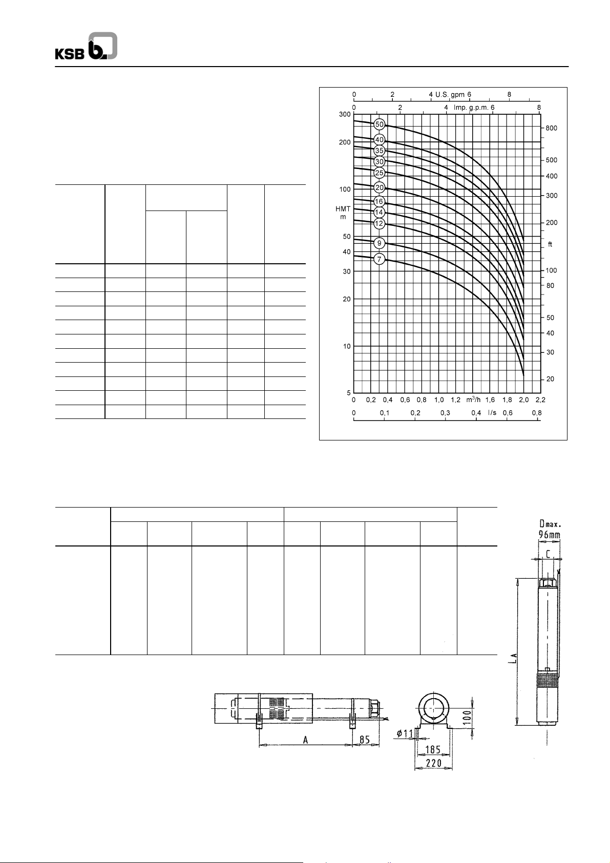
aed
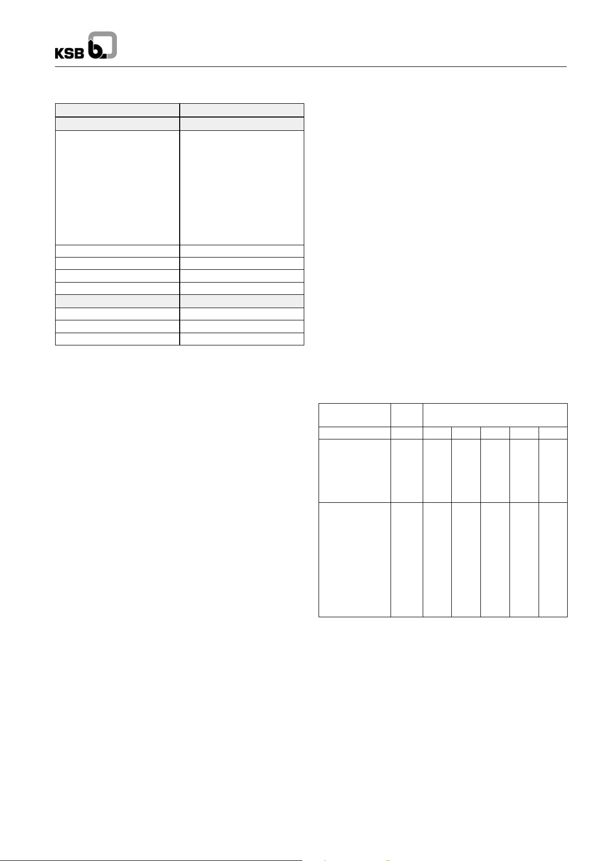
aed
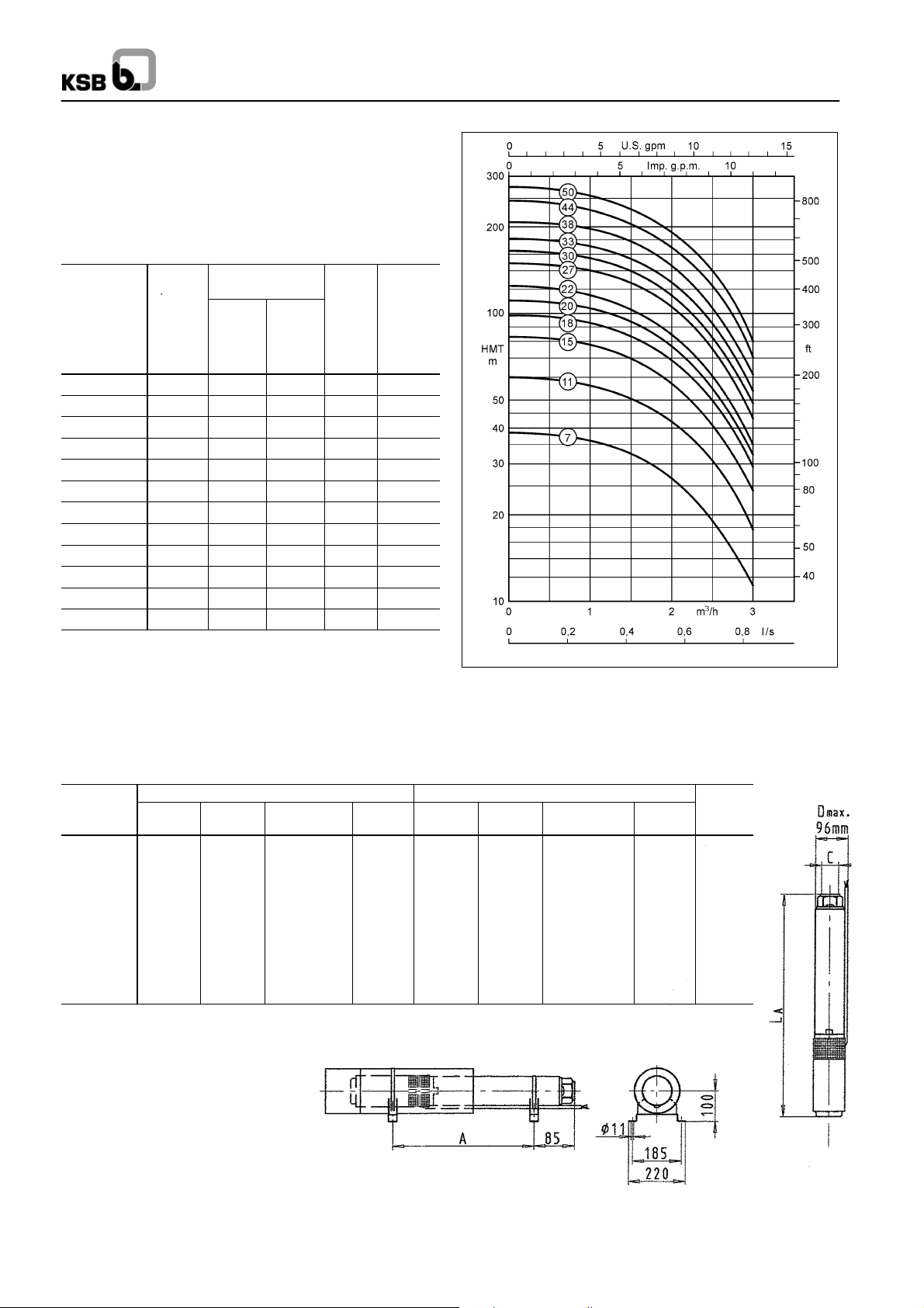
UPA 100C 2 -- ...
D1
ØD1max:
Pump = 96.5 mm
Pump with motor
= 98.0 mm
-- 7 2
-- 6 6
-- 6 0
-- 5 4
-- 4 7
-- 4 0
-- 3 5
-- 3 0
-- 2 1
-- 1 7
-- 1 3
-- 8
UPA 100C 2 -- ...
(Tolerances to ISO 2548
Class C, Annex B)
-- 2 5
-- 6
Rated Rated Rated current for
power
P
kW
0.37
0.37
0.55
0.75
1.1
1.1
1.5
1.5
2.2
2.2
2.2
3.0
3.0
3.0
power
(Motor)
P
N
HP
0.5
0.5
0.75
1.5
1.5
1~
220 V
N
I
3.2
3.6
5.7
1
6.9
8.0
8.9
2
9.5
2
11. 1
3
12.1
3
14.5
3
15.9
4
4
4
3~
400 V
1)
N
I
0.9
1.1
1.5
2.0
2.8
3.0
3.3
3.8
5.1
5.4
5.6
6.8
7.2
7.5
N
A
Operating range:
=0.5--2.5m3/h
Q
min
= End of characteristic curve
Q
max
A
--
--
--
(Motor)
Pump set
UPA 100C 2 --..
6
8
13
17
21
25
30
35
40
47
54
60
66
72
1)
Capacitor run motors (PSC motors) with starter.
Dimensions / Weights / Ident. Numbers
Pump set
UPA 100C 2 --..
6
8
13
17
21
25
30
35
40
47
54
60
66
72
A ≈ mm
349
397
517
623
711
807
928
1048
1169
1338
1506
1651
1796
1941
B ≈ mm C ≈ mm Ident. No. B ≈ mm C ≈ mm Ident. No. mA≈ kg
242
242
271
299
327
327
356
356
460
460
460
--
--
--
For horizontal installation, a device guiding the flow along the motor (cooling shroud, flow inducer sleeve, etc.) will be required.
1~ / 220 V 3~ / 400 V
591
639
788
922
1038
1134
1284
1404
1629
1798
1966
--
--
--
90 065 300
90 065 301
90 065 302
90 065 303
90 065 304
90 065 305
90 065 306
90 065 307
90 065 308
90 065 309
90 065 310
--
--
--
223
223
242
271
299
299
327
327
356
356
356
423
423
423
572
620
759
894
1010
1106
1255
1375
1525
1694
1862
2074
2219
2364
90 065 387
90 065 388
90 065 389
90 065 390
90 065 391
90 065 392
90 065 393
90 065 394
90 065 395
90 065 396
90 065 397
90 065 398
90 065 399
90 065 400
11. 1
11.7
14.3
17.0
19.5
20.8
23.7
25.4
28.1
29.5
32.6
37.0
38.9
40.9
Accessories: UPA Control for dry running protection see page 32.
27
Page 28
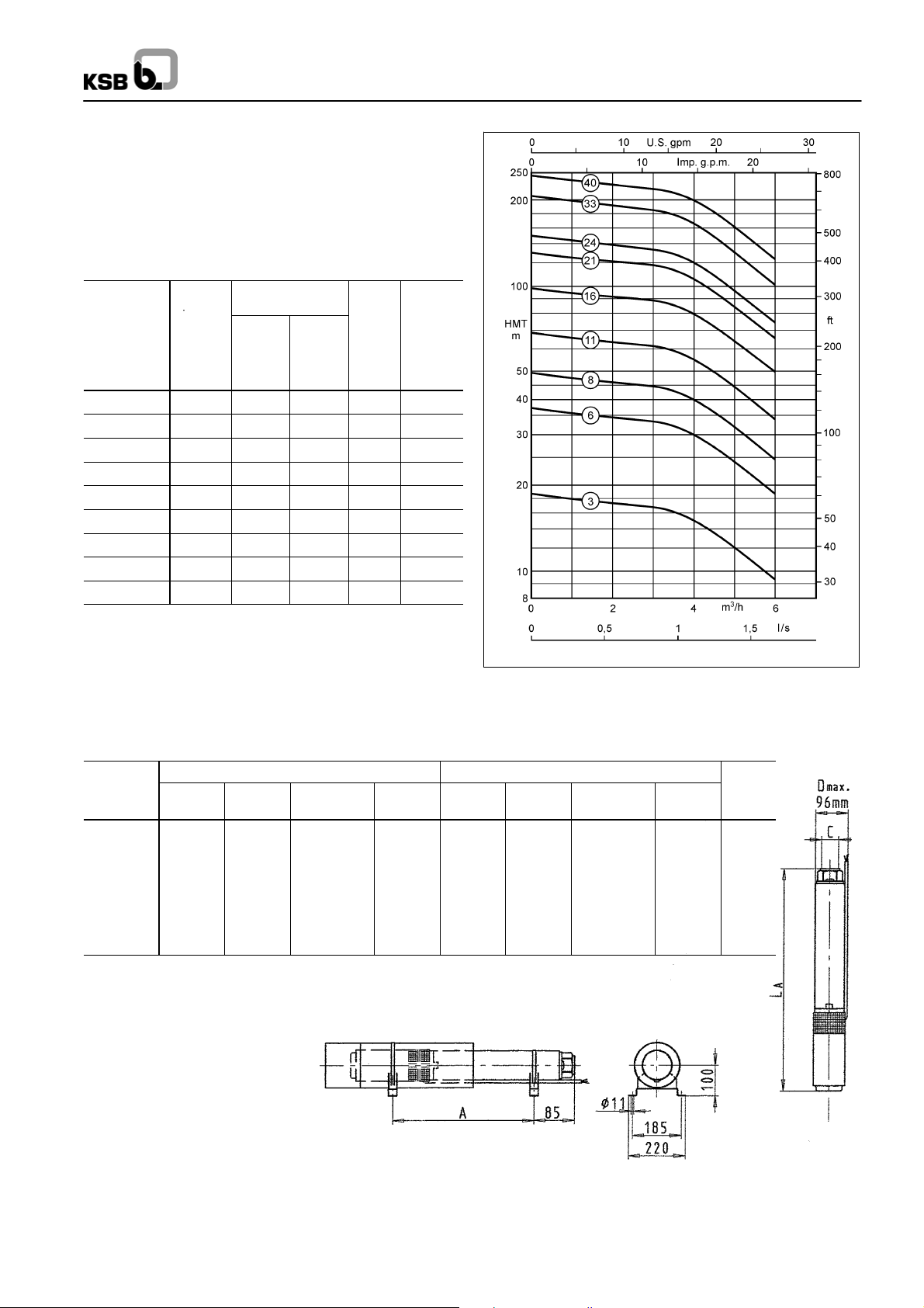
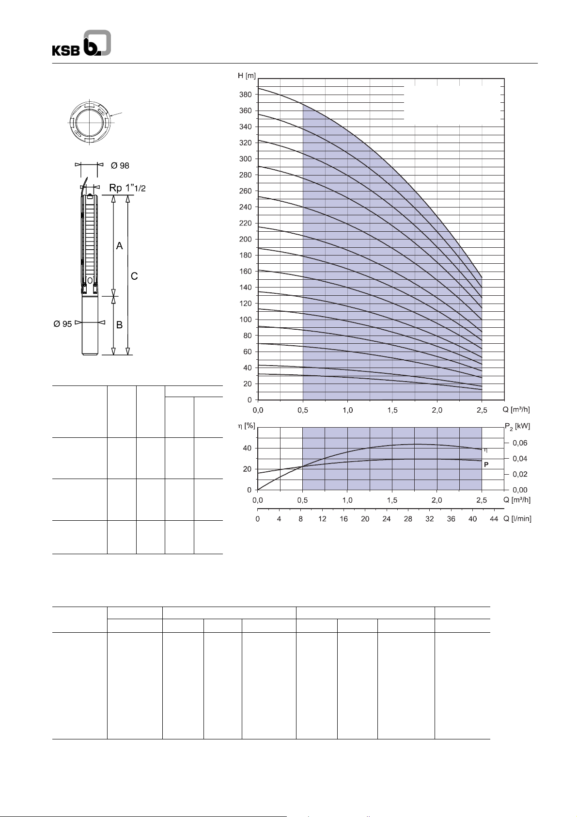
UPA 100C 3 -- ...
aed
aed
D1
ØD1max:
Pump = 96.5 mm
Pump with motor
= 98.0 mm
-- 6 8
-- 6 2
-- 5 7
-- 5 1
-- 4 4
-- 3 6
-- 3 0
-- 2 5
-- 2 2
-- 1 8
-- 1 5
-- 1 2
-- 9
-- 6
UPA 100C
UPA 100C 3 -- ...
(Tolerances to ISO 2548
Class C, Annex B)
Rated Rated
power
(Motor)
Pump set
UPA 100C 3 --..
6
9
12
15
18
22
25
30
36
44
51
57
62
68
1)
Capacitor run motors (PSC motors) with starter.
P
kW
0.37
0.55
0.75
1.1
1.1
1.5
1.5
2.2
2.2
3.0
3.0
3.7
3.7
4.0
N
power
(Motor)
P
N
HP
0.5
0.75
1.0
1.5
1.5
2.0
2.0
3.0
3.0
4.00
4.0
5.0
5.0
5.5
Rated current for
1~
220 V
I
N
3.6
5.7
6.9
8.7
8.9
9.8
11. 1
12.5
15.9
3~
400 V
1)
I
A
N
A
1.1
1.5
2.0
2.9
3.0
3.6
3.8
5.2
5.6
--
7.0
--
7.2
--
8.8
--
9.1
--
10.00
Operating range:
Q
=1.0--3.5m3/h
min
= End of characteristic curve
Q
max
Dimensions / Weights / Ident. Numbers
Pump set
UPA 100C 3 --..
6
9
12
15
18
22
25
30
36
44
51
57
62
68
A ≈ mm
349
421
493
566
638
734
807
928
1072
1265
1434
1579
1699
1844
B ≈ mm C ≈ mm Ident. No. B ≈ mm C ≈ mm Ident. No.
242
271
299
327
327
356
356
460
460
--
--
--
--
--
1~ / 220 V 3~ / 400 V
591
692
792
883
965
1090
1163
1388
1532
--
--
--
--
--
90 065 311
90 065 312
90 065 313
90 065 314
90 065 315
90 065 316
90 065 317
90 065 318
90 065 319
mA≈ kg
223
242
271
299
299
327
327
356
--
--
--
--
--
356
423
423
545
545
583
572
663
764
865
937
1061
1134
1284
1428
1688
1857
2124
2244
2427
90 065 401
90 065 402
90 065 403
90 065 404
90 065 405
90 065 406
90 065 407
90 065 408
90 065 409
90 065 410
90 065 411
90 065 412
90 065 413
90 065 414
11. 1
13.1
15.4
17.1
18.5
21.1
22.1
25.1
27.2
32.3
34.7
41.5
43.2
48.3
For horizontal installation, a device guiding the flow along the motor (cooling shroud, flow inducer sleeve, etc.) will be required.
Accessories: UPA Control for dry running protection see page 32.
28
Page 29
UPA 100C
aed
aed
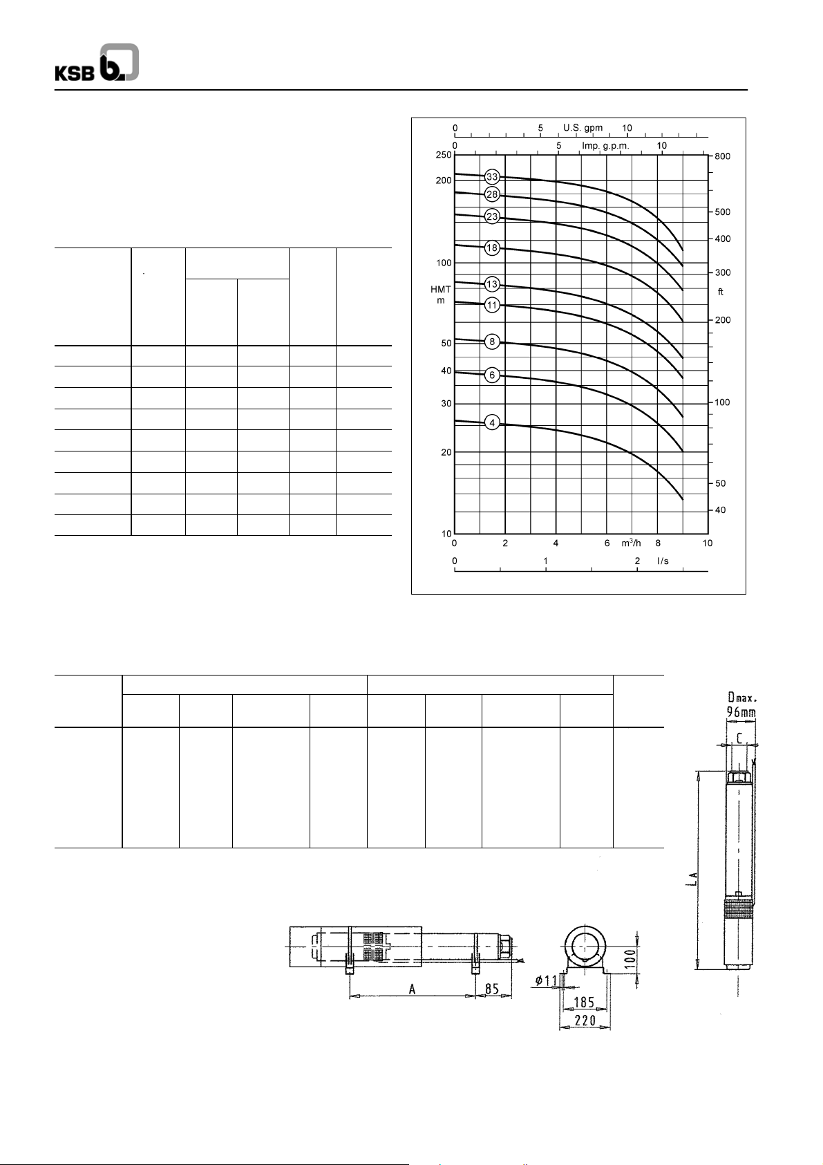
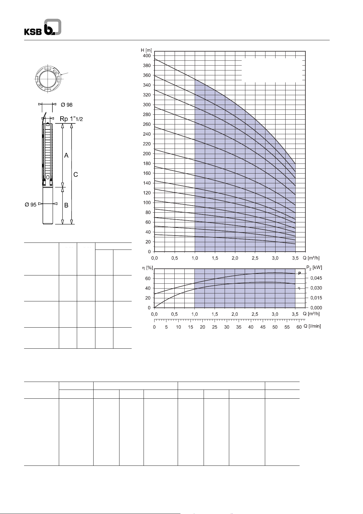
UPA 100C 4 -- ...
D1
ØD1max:
Pump = 96.5 mm
Pump with motor
= 98.0 mm
Rated Rated
power
(Motor)
Pump set
UPA 100C 4 --..
4
7
9
14
19
24
29
34
39
45
50
54
60
66
72
1)
Capacitor run motors (PSC motors) with starter.
P
kW
0.37
0.55
0.75
1.1
1.5
2.2
2.2
3.0
3.0
3.7
3.7
4.0
5.5
5.5
5.5
N
power
(Motor)
P
N
HP
0.5
0.75
1.0
1.5
2.0
3.0
3.0
4.0
4.0
5.0
5.0
5.5
7.5
7.5
7.5
Rated current for
1~
220 V
I
N
A
3.6
5.7
6.9
8.9
11. 1
12.8
15.9
--
--
--
--
--
--
--
--
-- 7 2
UPA 100C 4 -- ...
(Tolerances to ISO 2548
-- 6 6
-- 6 0
-- 5 4
-- 5 0
-- 4 5
-- 3 9
-- 3 4
-- 2 9
-- 2 4
-- 1 9
-- 1 4
-- 9
-- 7
-- 4
3~
400 V
1)
I
N
A
1.1
1.5
2.0
3.0
3.8
5.3
5.6
7.0
7.2
8.8
9.1
10.0
11. 5
12.5
13.2
Operating range:
=1.0--5.0m3/h
Q
min
= End of characteristic curve
Q
max
Class C, Annex B)
Dimensions / Weights / Ident. Numbers
Pump set
UPA 100C 4 --..
4
7
9
14
19
24
29
34
39
45
50
54
60
66
72
A ≈ mm
300
373
421
542
662
783
903
1024
1145
1289
1410
1506
1651
1796
1941
B ≈ mm C ≈ mm Ident. No. B ≈ mm C ≈ mm Ident. No.
242
271
299
327
356
460
460
--
--
--
--
--
--
--
--
For horizontal installation, a device guiding the flow along the motor (cooling shroud, flow inducer sleeve, etc.) will be required.
Accessories: UPA Control for dry running protection see page 32.
1~ / 220 V 3~ / 400 V
542
644
720
869
1018
1243
1363
--
--
--
--
--
--
--
--
90 065 320
90 065 321
90 065 322
90 065 323
90 065 324
90 065 325
90 065 326
--
--
--
--
--
--
--
--
223
242
271
299
327
356
356
423
423
545
545
583
698
698
698
523
615
692
841
989
1139
1259
1447
1568
1834
1955
2089
2349
2494
2639
90 065 415
90 065 416
90 065 417
90 065 418
90 065 419
90 065 420
90 065 421
90 065 422
90 065 423
90 065 424
90 065 425
90 065 426
90 065 427
90 065 428
90 065 429
mA≈ kg
10.5
12.5
14.5
17.4
20.4
23.5
25.2
29.4
31.1
38.0
39.7
44.3
51.6
53.7
55.7
29
Page 30
UPA 100C
aed
aed
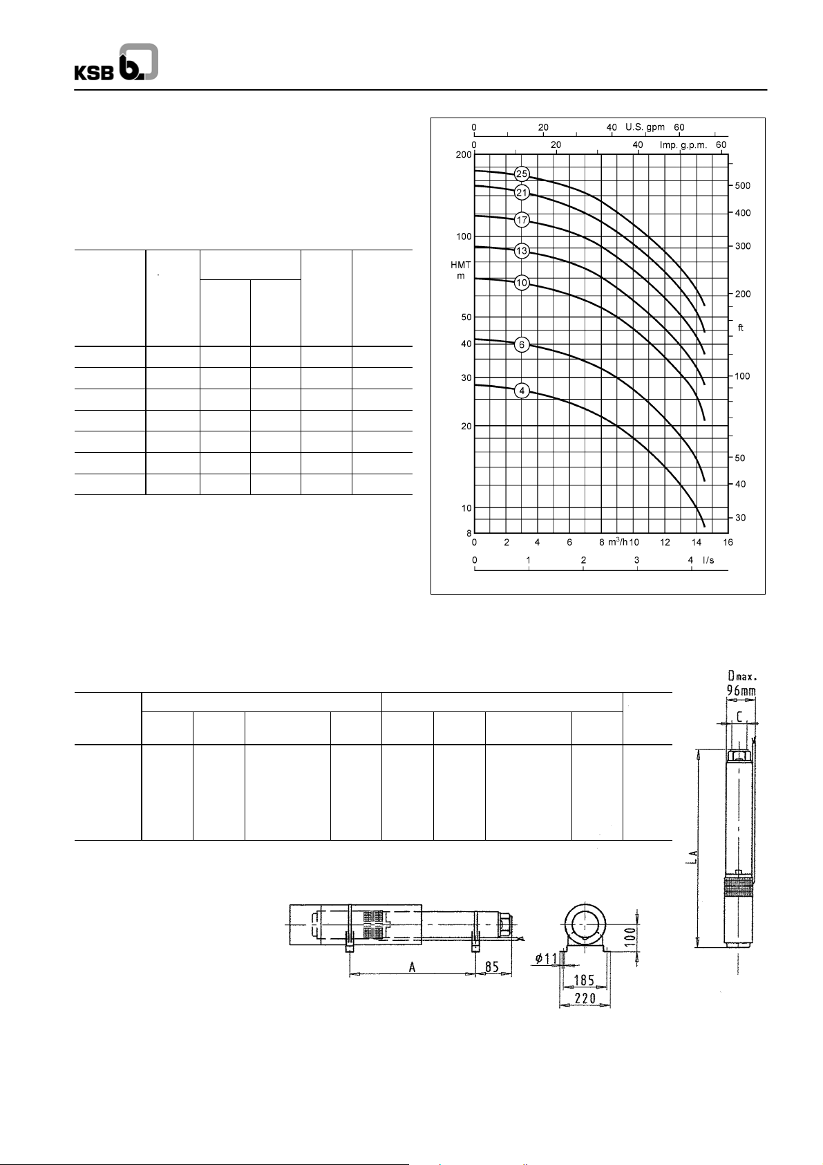
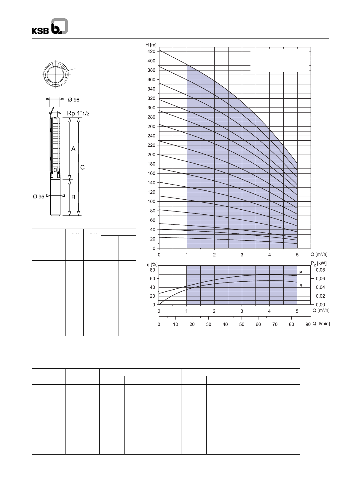
UPA 100C 7 -- ...
D1
ØD1max:
Pump = 96.5 mm
Pump with motor
= 98.0 mm
Rated Rated
power
(Motor)
Pump set
UPA 100C 7 --..
3
4
6
9
13
16
19
23
26
29
32
34
39
44
49
54
59
64
1)
Capacitor run motors (PSC motors) with starter.
P
kW
0.37
0.55
0.75
1.1
1.5
2.2
2.2
3.0
3.0
3.7
3.7
4.0
5.5
5.5
5.5
7.5
7.5
7.5
N
power
(Motor)
P
N
HP
0.5
0.75
1.0
1.5
2.0
3.0
3.0
4.0
4.0
5.0
5.0
5.5
7.5
7.5
7.5
10.0
10.0
10.0
Rated current for
1~
220 V
I
N
3.6
5.7
6.9
8.9
11. 1
12.8
15.9
3~
400 V
1)
I
A
N
A
1.1
1.5
2.0
3.0
3.8
5.2
5.6
--
6.6
--
7.2
--
8.3
--
9.1
--
10.0
--
11. 5
--
12.5
--
13.2
--
17.5
--
18.3
--
19.1
Operating range:
Q
=2.0--8.0m3/h
min
= End of characteristic curve
Q
max
Dimensions / Weights / Ident. Numbers
Pump set
UPA 100C 7 --..
3
4
6
9
13
16
19
23
26
29
32
34
39
44
49
54
59
64
A ≈ mm
276
300
349
421
517
590
662
759
831
903
976
1024
1145
1266
1386
1506
1628
1748
B ≈ mm C ≈ mm Ident. No. B ≈ mm C ≈ mm Ident. No.
242
271
299
327
356
460
460
--
--
--
--
--
--
--
--
--
--
--
1~ / 220 V 3~ / 400 V
519
571
648
748
873
1050
1122
--
--
--
--
--
--
--
--
--
--
--
90 065 327
90 065 328
90 065 329
90 065 330
90 065 331
90 065 332
90 065 333
UPA 100C 7 -- ...
-- 6 4
-- 5 9
-- 5 4
-- 4 9
-- 4 4
-- 3 9
-- 3 4
-- 3 2
-- 2 9
-- 2 6
-- 2 3
-- 1 9
-- 1 6
-- 1 3
-- 9
-- 6
-- 4
-- 3
223
242
271
299
327
356
--
--
--
--
--
--
--
--
--
--
--
356
423
423
545
545
583
698
698
698
774
774
774
500
542
620
720
844
946
1118
1182
1254
1448
1521
1607
1843
1964
2084
2280
2402
2522
(Tolerances to ISO 2548
Class C, Annex B)
90 065 430
90 065 431
90 065 432
90 065 433
90 065 434
90 065 435
90 065 436
90 065 437
90 065 438
90 065 439
90 065 440
90 065 441
90 065 442
90 065 443
90 065 444
90 065 445
90 065 446
90 065 447
mA≈ kg
10.2
11.5
13.5
15.8
18.5
21.0
22.0
25.9
27.0
33.0
34.0
37.9
45.0
46.8
48.6
53.9
55.7
59.5
For horizontal installation, a device guiding the flow along the motor (cooling shroud, flow inducer sleeve, etc.) will be required.
Accessories: UPA Control for dry running protection see page 32.
30
Page 31

UPA 100C
aed
aed
UPA 100C 12 -- ...
D1
ØD1max:
Pump = 96.5 mm
Pump with motor
= 98.0 mm
UPA 100C 12 -- ...
(Tolerances to ISO 2548
Class C, Annex B)
-- 2 7
-- 2 4
-- 2 0
-- 1 7
-- 1 4
-- 1 3
-- 1 0
-- 8
-- 5
Rated Rated
power
(Motor)
Pump set
UPA 100C 12 --..
3
5
8
10
13
14
17
20
24
27
1)
Capacitor run motors (PSC motors) with starter.
P
kW
1.1
1.5
2.2
3.0
3.7
4.0
5.5
5.5
7.5
7.5
N
power
(Motor)
P
N
HP
1.5
2.0
3.0
4.0
5.0
5.5
7.5
7.5
10.0
10.0
Rated current for
1~
220 V
I
N
8.9
11. 1
15.9
3~
400 V
1)
I
A
3.0
3.8
5.6
7.2
9.1
10.0
12.5
13.2
18.3
19.1
N
A
--
--
--
--
--
--
--
Operating range:
= 4.0 -- 15.0 m3/h
Q
min
= End of characteristic curve
Q
max
Dimensions / Weights / Ident. Numbers
Pump set
UPA 100C 12 --..
3
5
8
10
13
14
17
20
24
27
A ≈ mm
327
405
522
600
717
756
873
990
1146
1263
B ≈ mm C ≈ mm Ident. No. B ≈ mm C ≈ mm Ident. No.
327
356
460
--
--
--
--
--
--
--
1~ / 220 V 3~ / 400 V
654
761
982
--
--
--
--
--
--
--
90 065 334
90 065 335
90 065 336
-- 3
mA≈ kg
299
327
--
--
--
--
--
--
--
356
423
545
583
698
698
774
774
626
732
878
1023
1265
1339
1571
1688
1920
2037
90 065 448
90 065 449
90 065 450
90 065 451
90 065 452
90 065 453
90 065 454
90 065 455
90 065 456
90 065 457
13.9
16.0
18.7
22.1
28.4
29.6
36.4
37.7
44.1
45.4
For horizontal installation, a device guiding the flow along the motor (cooling shroud, flow inducer sleeve, etc.) will be required.
Accessories: UPA Control for dry running protection see page 32.
31
Page 32

UPA Control
0.3kg0.6k
g
Accessory: UPA Control for dry running protection (using 3 immersion electrodes)
Relay (A) Ident. No.
1.0to1.6 40 980 887
1.6to2.5 40 980 889
2.5to4.0 40 980 891
4.0to6.0 40 980 893
5.5to8.0 40 980 895
7.0to10 40 980 897
9.0to13 40 980 899
12 to 18 40 984 811
18 to 25 90 052 649
Combinations of UPA 100C with UPA Control 1~ 230 V
Ident. No. 40 980 891 40 980 893 40 980 895 40 980 897 40 980 899 40 984 811
2.5 to 4.0 4.0 to 6.0 5.5 to 8.0 7.0 to 10 9.0 to 13 12 to 18
UPA 100C 2 6, 8 13 17 21, 25, 30 35, 40 47, 54
UPA 100C 3 6 9 12 15, 18, 22 25, 30 36
UPA 100C 4 4 7 9 14 19 24, 29
UPA 100C 7 3 4 6 9 13 16, 19
UPA 100C 12
-- -- --
3 5 8
UPA 100C
Combinations of UPA 100C with UPA Control 3~ 400 V
Ident. No. 40 980
UPA 100C 2 6, 8, 13 17 21, 25, 30, 35 40, 47, 54 60, 66, 72
UPA 100C 3 6 9, 12 15, 18, 22, 25 30, 36 44, 51 57, 62 68
UPA 100C 4 4, 7 9 14, 19 24, 29 34, 39 45, 50 54, 60, 66 72
UPA 100C 7 3, 4 6 9, 13 16, 19 23, 26 29, 32 34, 39, 44 49, 54 59, 64
UPA 100C 12
887
1.0 to 1.6 1.6 to 2.5 2.5 to 4.0 4.0 to 6.0 5.5 to 8.0 7.0 to 10 9.0 to 13 12 to 18 18 to 25
-- --
40 980
889
40 980 891 40 980
893
40 980
895
40 980
897
40 980
899
40 984
811
-- -- -- --
-- --
3, 5 8 10 13 14 17, 20 24, 27
90 052
649
Accessory: cooling shroud made on stainless steel 1.4301
UPA 100C Type of
2/6 to 2/13
3/6 to 3/9
4/4 to 4/7
7/3 to 7/4
2/17 to 2/35
3/12 to 3/25
4/9 to 4/19
7/6 to 7/13
12/3 to 12/5
2/40 to 2/72
3/30 to 3/51
4/24 to 4/39
7/16 to 7/26
12/8 to 12/10
3/57 to 3/68
4/45 to 4/54
7/29 to 7/34
12/13 to 12/14
4/60 to 4/72
7/39 to 7/64
12/17 to 12/27
installation
v+h
v+h
v+h
v+h
v+h
v+h
v+h
v+h
v+h
v+h
v+h
v+h
v+h
v+h
v+h
v+h
v+h
v+h
v+h
v+h
v+h
Dimensions (diameter x length) mm
and motor type (kW)
Ø115 (130) x 400
for motor up to 0.55 kW (1~) or up to
0.55 kW (3~)
1.5 kg
Ø115 (130) x 500
for motor up to 1.5 kW (1~)
or up to 1.5 kW (3~)
1.8 kg
Ø115 (130) x 620
for motor up to 2.2 kW (1~)
or up to 3.0 kW (3~)
2.0 kg
Ø115 (130) x 800
for motor up to 4.0 kW (3~)
2.5 kg
Ø115 (130) x 1000
for motor up to 7.5 kW (3~)
3.0 kg
Cooling shroud
Ident. No.
90 066 478
90 066 479
90 066 480
90 066 481
90 066 482 90 066 484
Suction strainer
Ident. No.
90 065 494
Ø115x117
0.3 kg
Pedestals
Ident. No.
90 066 483
Set = 2 pcs.
0.6 kg
Set = 2 pcs.
1.4 kg
--
32
Page 33

50 Hz
UPA 150S
Applications
Suitable for handling clean or slightly contaminated water in
applications such as:
-- for domestic water supply
-- general water supply
-- irrigation and spray irrigation systems
-- artificial lowering of the ground water level as well as
-- heat transfer plants
In addition, the pump sets are used in pressure boosting
systems, air-conditioning systems, fountains, etc.
Permissible sand content in the fluid handled: 50 g/m
3
.
Operating Data
Capacity Q up to 85 m3/h..................
Head H up to 320 m.....................
Temperature of fluid handled t up to +50 °C.
Speed n ≈ 2900 rpm....................
Design
Single or multistage, single-entry centrifugal pumps with
shroud. For vertical and – depending on the number of stages
– horizontal installation. Radial or mixed flow hydraulics.
Suction casing fitted between pump and motor. Suction casing
equippedwith strainertoprotect thepump fromcoarse particles
in the liquid.
Check valve with threaded end integrated in the discharge
nozzle.
Particularlysuitable forverticalinstallationinnarrow deepwells.
Submersible Borehole Pumps
for Well Diameters of
150 mm (6 inches)
Designation (Example)
UPA 150 S -- 2 0 / 9
Type series
Minimum well diameter (mm)
Design status
3
Capacity (m
Number of stages
/h)
Certification
Quality management certified to ISO 9001
Available automation products:
• Hyamaster
• hyatronic
• switch gear
Product Features
-- Rust-proof
-- Suitable for installation in narrow deep wells
-- High efficiency
-- Motor designed for maximum pump output
-- Low noise level
-- For vertical, angled or horizontal installation
-- Check valve with anti-blockage valve disc
33
Page 34

50 Hz
UPA 150S
Selection Charts (Ranges on Offer) n ≈ 2900 rpm
Note:
The operating ranges ∆Q
following pages. The ∆Q
numbers on the following pages.
34
of the individual pump sizes are given in the characteristic curves for different stage numbers on the
A
operating ranges of the individual pump sizes are given in the characteristic curves for diffrent stage
B
Page 35

50 Hz
CrNisteel
CrNiMosteel
cae
UPA 150S
Material Variants
Component
Pump
Pump shroud /
Valve body
Suction casing
Stage casing /
Diffuser
Impeller Glass fibre reinforced NORYL (PPO)
Shaft
Spaltschutz PUR (polyurethane)
Bearings NBR 80 / 1.4404
Screws, bolts and
nuts
Component
Motor
Shaft
Bearing
carrier
Stator
case
DN 100
DN 150
UMA150D
DN 100
DN 150
UMA150D
DN 100
UMA150D
DN 150
G (Standard) B (Special)
CrNiMo steel
(1.4404)
Cast iron
(JL-1040)
Glass fibre reinforced NORYL (PPO)
Cr steel
(1.4028)
CrNiMo steel (A4--70)
Bronze
(CC480K-GS)
CrNiMo steel
(1.4462)
G (Standard) C1 (Special)
CrNi steel CrNiMo steel
(1.4305)
CrNi steel
(1.4301)
Cast iron
(JL--1030)
Cast iron
(JL--1030)
CrNi steel
(1.4301)
(1.4462)
CrNiMo steel
(1.4401)
-- -- --
CrNiMo steel
(1.4401)
CrNiMo steel
(1.4571)
-- -- --
Bearings / Lubrication
Radial plain bearings: pump bearings lubricated by the fluid
handled, motorbearings by themotor’s waterfill. Depending on
the number of stages, 1 or 2 intermediate bearingsare fitted on
the pump unit. Axial thrust is balanced by a tilting-pad thrust
bearing in the motor (lower end).
Direction of Rotation of the Pump
Clockwise rotation (when looking at the drive shaft end).
Pump End (Discharge Nozzle)
UPA 150S - 12 + 20: Internal thread G 2’’ (DN 50)
UPA 150S - 34, 48 + 65: Internal thread G 3’’ (DN 80)
Flanged end with adapter available.
Coating (Standard)
UMA 150D motor:
Quality 2-component high-build coating...........
Coating structure primer and top coat..
Film thickness 100 to 150
Colour ultramarine blue (RAL 5002)...........
DN 150 motor:
Quality powder coating, approved for...........
Colour steel blue, glossy (RAL 5011)...........
(epoxy resin base), approved for
drinking water contact
µm.....
drinking water contact
Type of Installation
Ingeneral, thepumps areinstalled vertically.Some modelsmay
also be installed horizontally depending on the number of
stages.
Drive
Design Canned
squirrel-cage motor, 2 poles
Connection NEMA standard..........
Type of enclosure IP 68....
Frequency f 50 Hz..........
Type of current three-phase (3 ~).......
Rated voltage U up to 500 V......
Rated power P
N
Frequency of starts 20 / h1)and 15 / h
up to 37 kW........
...
Minimum delay
before restarting 1 min......
Motor design is in compliance with VDE regulations.
1)
Motor DN 100
2)
Motor DN 150
3)
Motor UMA 150D
1) 2)
or wet3)submersible..............
2) 3)
Connection to Power Supply
The submersible motors are supplied ex factory with 1 or 2
motorleads, eachequipped with an earthconductor.All motors
are provided with internal earthing. Any extension cables
required are connected using water-tight cable connectors.
Motor leads and extension cables are suitable for drinking
water applications.
Starting
Motor DN 100 d.o.l. only.....
Motor UMA 150D
and DN 150 d.o.l. (autotransformer or soft starter).......
(autotransformer or soft starter)
or star-delta
Variable Speed
The submersible borehole pumps can also be equipped with a
speed control system to accommodate different operating
points.
Application Temperatures
The submersible borehole pumps are, as a standard, suitable
for use in water with temperatures of up to t = +30 °C. An
indispensable requirement for this is a flow velocity of
v =0.2 m/spast themotor.This requirement ismet, forexample,
when the pumpis installed ina deep well above the wellscreen
/filter,etc.
Withcertain restrictions, some motorsizes mayalso be used in
water with temperatures of up to t = +50 °C or for operation
without an adequate cooling flow of water past the motor, i.e.
v = 0 m/s (for example, when the unit is installed in a deep well
below the screen / filter area or in a pump sump, etc.).
Variants Available on Request
-- Other supply voltages up to 1000 V
-- Pump sets for 1
+ 2.5 kW/60 Hz
-- Models with cooling, suction or pressure shroud
~ /230Vupto2.2kW/50Hz
35
Page 36

Design Features
Check valve with anti-blockage
valve disc
-- No jamming or tilting.
-- Spring-loaded design makes for
minimum valve closing times and
prevents waterhammer.
-- High operating reliability.
Impellers and diffusers made of glass
fibre reinforced NORYL
-- Smooth surfaces for high efficiency
and minimum deposit build-up.
-- Excellent resistance to abrasion and
corrosion.
50 Hz
UPA 150S
All wetted plastic components are
approved for drinking water contact
1)
(BAM
-- Electric cables, seal elements,
1) German Federal Institute for Materials Research.
Stainless steel pump casing
-- Excellent resistance to
Enclosed pump bearing
-- No-maintenance design and high
-- For trouble-free long-term operation.
).
gaskets, etc. are absolutely fit for use
in drinking water applications.
corrosion.
wear resistance.
Protected clearance gap
-- Constant efficiency.
-- Minimum wear.
-- Long service life.
Stainless steel union elements
-- All wetted bolts, screws and nuts
are made of CrNiMo steel.
-- Excellent functional reliability.
-- Easy to remove and re-use even
after many years of operation.
Counter thrust bearing
-- Reliable balancing of negative axial thrust.
-- Impellers do not rub on the stage casings.
Tried and tested thrust bearing
-- Water-lubricated self-aligning tiltingpad journal bearing.
-- No-maintenance design suitable for
maximum load-carrying capacity
under continuous operation
conditions.
-- New materials combination (stainless steel / carbon) for high safety
factor.
Stainless steel pump shaft
-- Fully protected by impeller hubs and
sleeves from direct wear caused by
the fluid handled.
-- Multiple keyway profile for simple
assembly and dismantling of
impellers.
Submersible motor
-- VDE-compliant, i.e., high level of
electrical safety.
-- Designed for max. pump power to
protect unit from overloads.
-- Connection to NEMA standard.
Dynamically balanced rotor
-- Ensures smooth running.
Reliable pressure balancing system
-- Optimum rubber expansion
diaphragm design.
-- Enables installation at very low
depths.
36
Page 37

50 Hz
UPA 150S
37
Page 38

50 Hz
P
UPA 150S
UPA 150S -- 12 for Well Diameters of 150 mm (6 inches) and above
Pumps with submersible motors for ... -- Type of current / voltage three-phase (3 µ) / 400 V.........................
-- Starting d.o.l. (D) or star-delta (Y-∆)......................................
Pump + motor
UPA 150S -- 12 / .. + ...
2 + DN 100-1.1 24 1.1 30 (30) 3.1 73.5 0.71 4x1.5 -3 + DN 100-2.2 37 2.2 30 (30) 5.7 75.0 0.75 4x1.5 -4 + DN 100-2.2 48 2.2 30 (30) 5.7 75.0 0.75 4x1.5 -5 + DN 100-3 61 3.0 30 (30) 7.5 76.0 0.76 4x1.5 -6 + DN 100-3.7 73 3.7 30 (30) 8.7 77.5 0.80 4x1.5 -7 + DN 100-3.7 84 3.7 30 (30) 8.7 77.5 0.80 4x1.5 -8 + DN 100-5.5
9 + DN 100-5.5
10 + DN 100-5.5
6)
6)
6)
11 + DN 150-7.5 136 7.5 30 (30) 16.0 79.0 0.86 4x4.0 4/4 x 4.0
11 + UMA 150D 7/21 137 6.5 37 (33) 16.0 77.3 0.79 4x2.5 3/4 x 2.5
12 + DN 150-7.5 147 7.5 30 (30) 16.0 79.0 0.86 4x4.0 4/4 x 4.0
12 + UMA 150D 7/21 149 7.0 35 (31) 16.8 76.9 0.81 4x2.5 3/4 x 2.5
13 + DN 150-7.5 159 7.5 30 (30) 16.0 79.0 0.86 4x4.0 4/4 x 4.0
13 + UMA 150D 7/21 160 7.5 33 (28) 17.8 76.4 0.82 4x2.5 3/4 x 2.5
14 + DN 150-7.5 169 7.5 30 (30) 16.0 79.0 0.86 4x4.0 4/4 x 4.0
14 + UMA 150D 7/21 172 7.5 30 (24) 17.8 76.4 0.82 4x2.5 3/4 x 2.5
15 + DN 150-9.3 185 9.3 30 (30) 20.7 81.0 0.80 4x4.0 4/4 x 4.0
15 + UMA 150D 9/21 186 8.5 33 (28) 20.0 78.3 0.81 4x2.5 3/4 x 2.5
17 + DN 150-9.3 207 9.3 30 (30) 20.7 81.0 0.80 4x4.0 4/4 x 4.0
17 + UMA 150D 9/21 209 9.3 29 (23) 21.0 77.7 0.83 4x2.5 3/4 x 2.5
20 + DN 150-11 243 11. 0 30 (30) 23.1 81.0 0.85 4x4.0 4/4 x 4.0
20 + UMA 150D 13/21 249 11.5 34 (29) 26.5 80.6 0.79 4x2.5 3/4 x 2.5
23 + DN 150-15 283 15.0 30 (30) 31.2 81.0 0.86 4x4.0 4/4 x 4.0
23 + UMA 150D 13/21 284 13.0 30 (24) 29.0 80.2 0.81 4x2.5 3/4 x 2.5
25 + DN 150-15 306 15.0 30 (30) 31.2 81.0 0.86 4x4.0 4/4 x 4.0
25 + UMA 150D 15/21 310 14.0 34 (29) 30.5 82.1 0.82 4x4.0 3/4 x 2.5
28 + DN 150-15 339 15.0 30 (30) 31.2 81.0 0.86 4x4.0 4/4 x 4.0
28 + UMA 150D 15/21 344 15.0 30 (24) 32.5 81.7 0.83 4x4.0 3/4 x 2.5
1)
also see pages 3 and 35.
Dimensions / Weights / Horizontal Installation
Pump unit
UPA150S - 12/ .. UMA DN UMA DN UMA DN UMA DN UMA DN
2 450 -- 750 -- 750 -- 22 -- 23 143 -- -- v+h 515
3 450 -- 805 -- 805 -- 25 -- 26 143 -- -- v+h 545
4 538 -- 895 -- 895 -- 26 -- 27 143 -- -- v+h 630
5 538 -- 960 -- 960 -- 29 -- 30 143 -- -- v+h 665
6 626 -- 1185 -- 1185 -- 38 -- 39 143 -- -- v+h 820
7 626 -- 1185 -- 1185 -- 39 -- 40 143 -- -- v+h 820
8 813 -- 1520 -- 1520 -- 45 -- 46 143 -- -- v+h 1080
9 813 -- 1520 -- 1520 -- 46 -- 47 143 -- -- v+h 1080
10 813 -- 1520 -- 1520 -- 46 -- 47 143 -- -- v+h 1080
11 937 1660 1585 1670 -- 69 62 71 -- 147 149 v+h v 1210
12 937 1660 1585 1670 -- 69 62 71 -- 147 149 v+h v 1210
13 1069 1790 1715 1800 -- 71 64 73 -- 147 149 v+h v 1345
14 1069 1790 1715 1800 -- 71 64 73 -- 147 149 v+h v 1345
15 1069 1820 1750 1830 -- 74 67 76 -- 147 149 v+h v 1360
17 1157 1910 1835 1920 -- 75 68 77 -- 147 149 v+h v 1445
20 1289 2120 2000 2130 -- 84 73 87 -- 147 149 v+h v 1620
23 1421 2250 2200 2260 -- 89 83 91 -- 147 149 v+h v 1750
25 1564 2440 2340 2450 -- 94 84 96 -- 147 149 v v -28 1696 2570 2475 2580 -- 97 87 99 -- 147 149 v v --
1)
Including check valve with threaded end and standard motor leads.
4)
Always consult the manufacturer before attempting to install pumps sets supplied for vertical installation in horizontal position .
38
L
mm
P
Pump
Discharge
head
Q=0m
H
0
m
Rated
power
3
/h
P
N
kW
Max. temperature of
the fluid pumped
v ≥ 0.2m/s(=0m/s)
t
max
Motor Motor lead2),flat
_C
Rated
current
1)
I
N
A
Effi-
ciency
η
M
%
Power
factor
cos ϕ
-- -- --
Number x cross-section of
conductors (use under water,
D.o.l.
mm
400 V and ≤ +30 _C)
100 5.5 30 (30) 13.0 76.5 0.80 4x1.5 --
111 5.5 30 (30) 13.0 76.5 0.80 4x1.5 --
122 5.5 30 (30) 13.0 76.5 0.80 4x1.5 --
2)
3/4 = 1 x 3-core + 1 x 4-core, 90_ spacing.
5)
Motors DN 100 for d.o.l. starting only.
6)
with UMA 150D motor on request.
1)
L
≈ mm m
A
in ≈ kg D
A
G (Standard) B (Special) G (Standard) B (Special)
2)
v = vertical and h = horizontal.
in ≈ mm
max
D.o.l. Y-∆
Installation
2
Y-∆
mm
2) 4)
5)
2
A
≈ mm
Page 39

UPA 150S -- 12 / ..
Selection
The pressure lossesHvinthe checkvalve arenot
considered in the pump characteristic curves.
For more details anda selectionexample refer to
page 8.
Legend ...
H
: Head losses in the check valve
v
η
: Pump efficiency
p
(not considering check valve)
NPSH: Net positive suction head
required by the pump
Pump End G 2’’ / DN 50
The information given below is based on the
model “withcheck valve / connection branchand
threaded end”.
The outside diameter D
models (available with adapter) is as follows:
Flanged end DN 50: D
max
Threaded end to DIN ISO 228, Part 1.
Flange mating dimensions to DIN 2501, Part 1
on “flanged end”
max
= 165 mm.
50 Hz
UPA 150S
UPA 150S -- 12 /..
(Tolerances to
ISO 9906 Class 2 / Annex A)
Operating range:
Q
=3m3/h
min
= End of characteristic curve
Q
max
39
Page 40

50 Hz
P
UPA 150S
UPA 150S -- 20 for Well Diameters of 150 mm (6 inches) and above
Pumps with submersible motors for ... -- Type of current / voltage three-phase (3~) / 400 V...........................
-- Starting d.o.l. (D) or star-delta (Y-∆)......................................
Pump + motor Pump Motor Motor cable2),flat
Discharge
head
Q=0m3/h
H
0
UPA 150S -- 20 / .. + ...
2 + DN 100-2.2 25 2.2 30 (30) 5.7 75.0 0.75 4x1.5 -3 + DN 100-3 37.5 3.0 30 (30) 7.5 76.0 0.76 4x1.5 -4 + DN 100-3.7 49 3.7 30 (30) 8.7 77.5 0.80 4x1.5 -5 + DN 100-5.5
6 + DN 100-5.5
7 + DN 100-5.5
8 + DN 150-7.5 99 7.5 30 (30) 16.0 79.0 0.86 4x4.0 4/4 x 4.0
8 + UMA 150D 7/21 100 6.5 36 (32) 16.0 77.3 0.79 4x2.5 3/4 x 2.5
9 + DN 150-7.5 111 7.5 30 (30) 16.0 79.0 0.86 4x4.0 4/4 x 4.0
9 + UMA 150D 7/21 11 2 7.5 33 (27) 17.8 76.4 0.82 4x2.5 3/4 x 2.5
10 + DN 150-9.3 125 9.3 30 (30) 20.7 81.0 0.80 4x4.0 4/4 x 4.0
10 + UMA 150D 9/21 126 8.5 34 (29) 20.0 78.3 0.81 4x2.5 3/4 x 2.5
11 + DN 150-9.3 136 9.3 30 (30) 20.7 81.0 0.80 4x4.0 4/4 x 4.0
11 + UMA 150D 9/21 137 9.0 31 (26) 20.5 77.9 0.82 4x2.5 3/4 x 2.5
12 + DN 150-9.3 147 9.3 30 (30) 20.7 81.0 0.80 4x4.0 4/4 x 4.0
12 + UMA 150D 9/21 148 9.3 28 (22) 21.0 77.7 0.83 4x2.5 3/4 x 2.5
13 + DN 150-11 160 11. 0 30 (30) 23.1 81.0 0.85 4x4.0 4/4 x 4.0
13 + UMA 150D 13/21 164 11.0 36 (31) 25.5 80.7 0.78 4x2.5 3/4 x 2.5
14 + DN 150-11 171 11. 0 30 (30) 23.1 81.0 0.85 4x4.0 4/4 x 4.0
14 + UMA 150D 13/21 176 11.5 34 (29) 26.5 80.6 0.79 4x2.5 3/4 x 2.5
15 + DN 150-15 187 15.0 30 (30) 31.2 81.0 0.86 4x4.0 4/4 x 4.0
15 + UMA 150D 13/21 188 12.5 32 (26) 28.0 80.4 0.80 4x2.5 3/4 x 2.5
17 + DN 150-15 210 15.0 30 (30) 31.2 81.0 0.86 4x4.0 4/4 x 4.0
17 + UMA 150D 15/21 213 14.0 34 (29) 30.5 82.1 0.82 4x4.0 3/4 x 2.5
20 + DN 150-18.5 247 18.5 30 (30) 38.3 82.0 0.85 4x4.0 4/4 x 4.0
20 + UMA 150D 18/21 251 16.5 32 (26) 37.0 82.2 0.79 4x4.0 3/4 x 2.5
23 + DN 150-18.5 280 18.5 30 (30) 38.3 82.0 0.85 4x4.0 4/4 x 4.0
23 + UMA 150D 18/21 286 18.5 27 (20) 40.5 81.7 0.81 4x4.0 3/4 x 2.5
28 + DN 150-22 342 22.0 30 (30) 44.6 83.0 0.86 4x4.0 4/4 x 4.0
28 + UMA 150D 22/21 349 22.0 29 (22) 47.5 83.3 0.81 4x4.0 3/4 x 2.5
1)
also see pages 3 and 35.
6)
6)
6)
m
63 5.5 30 (30) 13.0 76.5 0.80 4x1.5 -75 5.5 30 (30) 13.0 76.5 0.80 4x1.5 -86 5.5 30 (30) 13.0 76.5 0.80 4x1.5 --
2)
3/4 = 1 x 3-core + 1 x 4-core, 90_ spacing.
Rated
power
P
N
kW
Max. temperature of
the fluid pumped
v ≥ 0.2m/s(=0m/s)
1)
t
max
_C
5)
Motors DN 100 for d.o.l. starting only.
Rated
current
I
N
A
Effi-
ciency
η
M
%
Power
factor
cos ϕ
-- -- --
Number x cross-section of
conductors (use under water,
400 V and ≤ +30 _C)
D.o.l.
2
mm
6)
with UMA 150D motors on request.
Y-∆
mm
5)
2
Dimensions / Weights / Horizontal Installation
L
P
mm
G (Standard) B (Special) G (Standard) B (Special)
UPA150S - 20/ ..
2 494 -- 850 -- 850 -- 26 -- 27 143 -- -- v+h 585
3 494 -- 920 -- 920 -- 29 -- 30 143 -- -- v+h 620
4 604 -- 1160 -- 1160 -- 38 -- 39 143 -- -- v+h 795
5 604 -- 1310 -- 1310 -- 43 -- 44 143 -- -- v+h 870
6 714 -- 1420 -- 1420 -- 44 -- 45 143 -- -- v+h 980
7 714 -- 1420 -- 1420 -- 45 -- 46 143 -- -- v+h 980
8 860 1580 1510 1590 -- 68 61 70 -- 147 149 v+h v 1135
9 970 1690 1620 1700 -- 69 62 71 -- 147 149 v+h v 1245
10 970 1720 1650 1730 -- 72 64 74 -- 147 149 v+h v 1260
11 1080 1830 1760 1840 -- 73 66 75 -- 147 149 v+h v 1370
12 1080 1830 1760 1840 -- 73 66 75 -- 147 149 v+h v 1370
13 1190 2020 1905 2030 -- 82 71 84 -- 147 149 v+h v 1520
14 1190 2020 1905 2030 -- 82 71 84 -- 147 149 v+h v 1520
15 1300 2130 2080 2140 -- 83 78 85 -- 147 149 v+h v 1630
17 1410 2285 2190 2295 -- 89 79 91 -- 147 149 v+h v 1760
20 1575 2495 2420 2505 -- 97 90 99 -- 147 149 v+h v 1950
23 1740 2660 2585 2670 -- 100 93 102 -- 147 149 v v -28 2015 3025 2925 3035 -- 112 103 114 -- 147 149 v v --
1)
Including check valve with threaded end and standard motor leads.
4)
Always consult the manufacturer before attempting to install pumps sets supplied for vertical installation in horizontal position .
UMA DN UMA DN UMA DN UMA DN UMA DN
L
≈ mm m
A
2)
v = vertical h = horizontal.
1)
in ≈ kg D
A
in ≈ mm
max
D.o.l. Y-∆
Installation
40
2) 4)
A
≈ mm
Page 41

UPA 150S -- 20 / ..
Selection
The pressure lossesHvinthe checkvalve arenot
considered in the pump characteristic curves.
For more details anda selectionexample refer to
page 8.
Legend ...
H
: Head losses in the check valve
v
η
: Pump efficiency
p
(not considering check valve)
NPSH: Net positive suction head
required by the pump
Pump End G 2’’ / DN 50
The information given below is based on the
model “withcheck valve / connection branchand
threaded end”.
The outside diameter D
models (available with adapter) is as follows:
Flanged end DN 50: D
max
Threaded end to DIN ISO 228, Part 1
Flange mating dimensions to DIN 2501, Part 1
on “flanged end”
max
= 165 mm
50 Hz
UPA 150S
UPA 150S -- 20 /..
(Tolerances to
ISO 9906 Class 2 / Annex A)
Operating range:
Q
=4m3/h
min
= End of characteristic curve
Q
max
41
Page 42

50 Hz
P
UPA 150S
UPA 150S -- 34 for Well Diameters of 150 mm (6 inches) and above
Pumps with submersible motors for ... -- Type of current / voltage three-phase (3~) / 400 V...........................
-- Starting d.o.l. (D) or star-delta (Y-∆)......................................
Pump + motor Pump Motor Motor lead2),flat
Discharge
head
Q=0m3/h
H
UPA 150S -- 34 / .. + ...
1 + DN 100--1.1 13.2 1.1 30 (30) 3.1 73.5 0.71 4x1.5 -- -2 + DN 100--2.2 26 2.2 30 (30) 5.7 75.0 0.75 4x1.5 -- -3 + DN 100--3.7 39.5 3.7 30 (30) 8.7 77.5 0.80 4x1.5 -- -4 + DN 100--5.5
5 + DN 100--5.5
6 + DN 150--7.5 80 7.5 30 (30) 16.0 79.0 0.86 4x4.0 4/4 x 4.0
6 + UMA 150D 7/21 81 6.5 36 (32) 16.0 77.3 0.79 4x2.5 3/4 x 2.5
7 + DN 150--7.5 92 7.5 30 (30) 16.0 79.0 0.86 4x4.0 4/4 x 4.0
7 + UMA 150D 7/21 94 7.5 31 (26) 17.8 76.4 0.82 4x2.5 3/4 x 2.5
8 + DN 150--9.3 107 9.3 30 (30) 20.7 81.0 0.80 4x4.0 4/4 x 4.0
8 + UMA 150D 9/21 108 9.0 32 (27) 20.5 77.9 0.82 4x2.5 3/4 x 2.5
9 + DN 150--9.3 119 9.3 30 (30) 20.7 81.0 0.80 4x4.0 4/4 x 4.0
9 + UMA 150D 9/21 120 9.3 28 (22) 21.0 77.7 0.83 4x2.5 3/4 x 2.5
10 + DN 150--11 132 11. 0 30 (30) 23.1 81.0 0.85 4x4.0 4/4 x 4.0
10 + UMA 150D 13/21 136 11.0 35 (30) 25.5 80.7 0.78 4x2.5 3/4 x 2.5
11 + DN 150--15 148 15.0 30 (30) 31.2 81.0 0.86 4x4.0 4/4 x 4.0
11 + UMA 150D 13/21 149 12.0 32 (27) 27.0 80.5 0.80 4x2.5 3/4 x 2.5
12 + DN 150--15 161 15.0 30 (30) 31.2 81.0 0.86 4x4.0 4/4 x 4.0
12 + UMA 150D 13/21 161 13.0 29 (23) 29.0 80.2 0.81 4x2.5 3/4 x 2.5
14 + DN 150--15 185 15.0 30 (30) 31.2 81.0 0.86 4x4.0 4/4 x 4.0
14 + UMA 150D 15/21 188 15.0 31 (25) 32.5 81.7 0.83 4x4.0 3/4 x 2.5
17 + DN 150--18.5 224 18.5 30 (30) 38.3 82.0 0.85 4x4.0 4/4 x 4.0
17 + UMA 150D 18/21 228 18.5 27 (20) 40.5 81.7 0.81 4x4.0 3/4 x 2.5
19 + DN 150--22 253 22.0 30 (30) 44.6 83.0 0.86 4x4.0 4/4 x 4.0
19 + UMA 150D 22/21 257 21.0 32 (26) 46.0 83.5 0.80 4x4.0 3/4 x 2.5
21 + DN 150--22 277 22.0 30 (30) 44.6 83.0 0.86 4x4.0 4/4 x 4.0
21 + UMA 150D 22/21 282 22.0 28 (22) 47.5 83.3 0.81 4x4.0 3/4 x 2.5
1)
also see pages 3 and 35.
6)
6)
0
m
54 5.5 30 (30) 13.0 76.5 0.80 4x1.5 -- -67 5.5 30 (30) 13.0 76.5 0.80 4x1.5 -- --
2)
3/4 = 1 x 3-core + 1 x 4-core. 90_ spacing.
Rated
power
P
N
kW
Max. temperature
of the fluid pumped
v ≥ 0.2m/s(=0m/s)
1)
t
max
_C
5)
Motors DN 100 for d.o.l. starting only.
Rated
current
I
N
A
Effi-
ciency
η
M
%
Power
factor
cos ϕ
-- -- --
Number x cross-section of
conductors (use under water,
400 V and ≤ +30 _C)
D.o.l.
2
mm
6)
with UMA 150D motors on request.
Y-∆
mm
5)
2
Dimensions / Weights / Horizontal Installation
L
P
mm
G (Standard) B (Special) G (Standard) B (Special)
LA≈ mm mAin ≈ kg D
1)
in ≈ mm
max
D.o.l. Y-∆
Installation
UPA150S - 34/ .. UMA DN UMA DN UMA DN UMA DN UMA DN
1 495 -- 795 -- 795 -- 22 -- 23 143 -- -- v+h 560
2 495 -- 850 -- 850 -- 26 -- 27 143 -- -- v+h 590
3 605 -- 1160 -- 1160 -- 38 -- 39 143 -- -- v+h 800
4 715 -- 1420 -- 1420 -- 44 -- 45 143 -- -- v+h 985
5 825 -- 1530 -- 1530 -- 46 -- 47 143 -- -- v+h 1095
6 970 1690 1620 1700 -- 69 62 71 -- 147 149 v+h v 1245
7 1080 1800 1730 1810 -- 71 64 73 -- 147 149 v+h v 1355
8 1190 1940 1870 1950 -- 75 68 77 -- 147 149 v+h v 1480
9 1300 2050 1980 2060 -- 77 70 79 -- 147 149 v+h v 1590
10 1410 2240 2125 2250 -- 85 74 88 -- 147 149 v+h v 1740
11 1520 2350 2300 2360 -- 90 84 92 -- 147 149 v+h v 1850
12 1630 2460 2410 2470 -- 92 86 94 -- 147 149 v+h v 1960
14 1850 2725 2630 2735 -- 99 89 101 -- 147 149 v v -17 2180 3100 3025 3110 -- 108 101 11 0 -- 147 149 v v -19 2400 3410 3310 3420 -- 119 111 122 -- 147 149 v v -21 2620 3630 3530 3640 -- 123 114 125 -- 147 149 v v --
1)
Including check valve with threaded end and standard motor leads.
2)
v = vertical and h = horizontal.
42
2)
A
≈ mm
Page 43

UPA 150S -- 34 / ..
Selection
The pressure lossesHvinthe checkvalve arenot
considered in the pump characteristic curves.
For more details anda selectionexample refer to
page 8.
Legend ...
H
: Head losses in the check valve
v
η
: Pump efficiency
p
(not considering check valve)
NPSH: Net positive suction head
required by the pump
Pump End G 3’’ / DN 80
The information given below is based on the
model “withcheck valve / connection branchand
threaded end”.
The outside diameter D
models (available with adapter) is as follows:
Flanged end DN 80: D
Threaded end to DIN ISO 228, Part 1.
Flange mating dimensions to DIN 2501, Part 1
on “flanged end ”
max
= 200 mm
max
50 Hz
UPA 150S
UPA 150S -- 34 /..
(Tolerances to
ISO 9906 Class 2 / Annex A)
Operating range:
Q
=7m3/h
min
= End of characteristic curve
Q
max
43
Page 44

50 Hz
P
UPA 150S
UPA 150S -- 48 for Well Diameters of 150 mm (6 inches) and above
Pumps with submersible motors for ... -- Type of current / voltage three-phase (3~) / 400 V...........................
-- Starting d.o.l. (D) or star-delta (Y-∆)......................................
Pump + motor Pump Motor Motor lead2),flat
Discharge
head
Q=0m3/h
H
UPA 150S -- 48 / .. + ...
1 + DN 100-2.2 15.2 2.2 30 (30) 5.7 75.0
2 + DN 100-3.7 29.5 3.7 30 (30) 8.7 77.5
3 + DN 100-5.5
4 + DN 150-7.5 60 7.5 30 (30) 16.0 79.0
4 + UMA 150D 7/21 61 7.5 32 (27) 17.8 76.4
5 + DN 150-9.3 76 9.3 30 (30) 20.7 81.0
5 + UMA 150D 9/21 76 9.3 30 (24) 21.0 77.7
6 + DN 150-11 90 11. 0 30 (30) 23.1 81.0
6 + UMA 150D 13/21 93 11. 5 34 (29) 26.5 80.6
7 + DN 150-15 107 15.0 30 (30) 31.2 81.0
7 + UMA 150D 13/21 107 13.0 30 (24) 29.0 80.2
8 + DN 150-15 121 15.0 30 (30) 31.2 81.0
8 + UMA 150D 15/21 122 15.0 32 (26) 32.5 81.7
9 + DN 150-18.5 136 18.5 30 (30) 38.3 82.0
9 + UMA 150D 18/21 139 16.5 31 (25) 37.0 82.2
10 + DN 150-18.5 150 18.5 30 (30) 38.3 82.0
10 + UMA 150D 18/21 153 18.5 27 (20) 40.5 81.7
11 + DN 150-22 167 22.0 30 (30) 44.6 83.0
11 + UMA 150D 22/21 170 21.0 32 (27) 46.0 83.5
12 + DN 150-22 181 22.0 30 (30) 44.6 83.0
12 + UMA 150D 22/21 184 22.0 29 (23) 47.5 83.3
13 + UMA 150D 26/21 201 24.0 35 (30) 52.0 84.9
15 + UMA 150D 30/21 232 28.0 33 (28) 61.0 84.7
17 + UMA 150D 37/22 263 32.0 45 (40) 71.0 84.2
1)
also see pages 3 and 35.
5)
Motors DN 100 for d.o.l. starting only.
6)
0
m
46 5.5 30 (30) 13.0 76.5
Rated
power
Max. temperature
of the fluid pumped
v ≥ 0.2m/s(=0m/s)
P
N
kW
2)
3/4 = 1 x 3-core + 1 x 4-core, 90_ spacing.
6)
with UMA 150D motors on request.
t
max
_C
Rated
current
Effi-
ciency
Power
factor
Number x cross-section of
conductors (use under water,
400 V and ≤ +30 _C)
1)
I
N
A
η
cos ϕ
M
%
-- -- --
D.o.l.
mm
2
0.75 4x1.5 --
0.80 4x1.5 --
0.80 4x1.5 --
0.86 4x4.0 4/4 x 4.0
0.82 4x2.5 3/4 x 2.5
0.80 4x4.0 4/4 x 4.0
0.83 4x2.5 3/4 x 2.5
0.85 4x4.0 4/4 x 4.0
0.79 4x2.5 3/4 x 2.5
0.86 4x4.0 4/4 x 4.0
0.81 4x2.5 3/4 x 2.5
0.86 4x4.0 4/4 x 4.0
0.83 4x4.0 3/4 x 2.5
0.85 4x4.0 4/4 x 4.0
0.79 4x4.0 3/4 x 2.5
0.85 4x4.0 4/4 x 4.0
0.81 4x4.0 3/4 x 2.5
0.86 4x4.0 4/4 x 4.0
0.80 4x4.0 3/4 x 2.5
0.86 4x4.0 4/4 x 4.0
0.81 4x4.0 3/4 x 2.5
0.80 4x6.0 3/4 x 4.0
0.79 4x6.0 3/4 x 4.0
4)
3/4 x 4.0
4)
Parallel cable.
0.78 3/4 x 4.0
Y-∆
mm
5)
2
Dimensions / Weights / Horizontal Installation
L
P
mm
G (Standard) B (Special) G (Standard) B (Special)
LA≈ mm mAin ≈ kg D
1)
in ≈ mm
max
D.o.l. Y-∆
Installation
UPA150S - 48/ .. UMA DN UMA DN UMA DN UMA DN UMA DN
1 495 -- 850 -- 850 -- 25 -- 26 143 -- -- v+h 590
2 495 -- 1050 -- 1050 -- 37 -- 38 143 -- -- v+h 690
3 605 -- 1310 -- 1310 -- 43 -- 44 143 -- -- v+h 875
4 750 1470 1400 1480 -- 67 60 69 -- 147 149 v+h v 1025
5 860 1610 1540 1620 -- 71 63 73 -- 147 149 v+h v 1150
6 970 1800 1685 1810 -- 80 69 82 -- 147 149 v+h v 1300
7 1080 1910 1860 1920 -- 81 76 83 -- 147 149 v+h v 1410
8 1190 2065 1970 2075 -- 88 78 90 -- 147 149 v+h v 1540
9 1300 2220 2145 2230 -- 93 86 95 -- 147 149 v+h v 1675
10 1410 2330 2255 2340 -- 94 87 96 -- 147 149 v+h v 1785
11 1520 2530 2430 2540 -- 106 97 108 -- 147 149 v+h v 1940
12 1630 2640 2540 2650 -- 108 99 110 -- 147 149 v+h v 2050
13 1740 2855 -- 2865 -- 118 -- 121 -- 149 149 v -- -15 1960 3175 -- 3185 -- 132 -- 134 -- 149 149 v -- -17 2180 3475 -- 3485 -- 142 -- 144 -- 149 149 v -- --
1)
Including check valve with threaded end and standard motor leads.
2)
v = vertical h = horizontal.
44
2)
A
≈ mm
Page 45

UPA 150S -- 48 / ..
Selection
The pressure lossesHvinthe checkvalve arenot
considered in the pump characteristic curves.
For more details anda selectionexample refer to
page 8.
Legend ...
H
: Head losses in the check valve
v
η
: Pump efficiency
p
(not considering check valve)
NPSH: Net positive suction head
required by the pump
Pump End G 3’’ / DN 80
The information given below is based on the
model “withcheck valve / connection branchand
threaded end”.
The outside diameter D
models (available with adapter) is as follows:
Flanged end DN 80: D
max
Threaded end to DIN ISO 228, Part 1
Flange mating dimensions to DIN 2501, Part 1
on “flanged end”
max
= 200 mm
50 Hz
UPA 150S
UPA 150S -- 48 /..
(Tolerances to
ISO 9906 Class 2 / Annex A)
Operating range:
Q
=9m3/h
min
= End of characteristic curve
Q
max
45
Page 46

50 Hz
UPA 150S
UPA 150S -- 65 for Well Diameters of 150 mm (6 inches) and above
Pumps with submersible motors for... -- Type of current / voltage three-phase (3~) / 400 V...........................
-- Starting d.o.l. (D) or star-delta (Y-∆)......................................
Pump + motor Pump Motor Motor lead2),flat
Discharge
head
Q=0m
H
UPA 150S -- 65 / .. + ...
1 + DN 100-2.2 13.8 2.2 30 (30) 5.7 75.0 0.75 4x1.5 -2 + DN 100-5.5
3 + DN 150-7.5 42 7.5 30 (30) 16.0 79.0 0.86 4x4.0 4/4 x 4.0
3 + UMA 150D 7/21 42 6.5 37 (33) 16.0 77.3 0.79 4x2.5 3/4 x 2.5
4 + DN 150-9.3 56 9.3 30 (30) 20.7 81.0 0.80 4x4.0 4/4 x 4.0
4 + UMA 150D 9/21 56 8.5 34 (29) 20.0 78.3 0.81 4x2.5 3/4 x 2.5
5 + DN 150-11 69 11. 0 30 (30) 23.1 81.0 0.85 4x4.0 4/4 x 4.0
5 + UMA 150D 13/21 71 10.5 36 (32) 25.0 80.8 0.76 4x2.5 3/4 x 2.5
6 + DN 150-15 84 15.0 30 (30) 31.2 81.0 0.86 4x4.0 4/4 x 4.0
6 + UMA 150D 13/21 84 12.5 31 (26) 28.0 80.4 0.80 4x2.5 3/4 x 2.5
7 + DN 150-15 97 15.0 30 (30) 31.2 81.0 0.86 4x4.0 4/4 x 4.0
7 + UMA 150D 15/21 98 14.5 33 (27) 31.5 81.9 0.82 4x4.0 3/4 x 2.5
8 + DN 150-18.5 111 18.5 30 (30) 38.3 82.0 0.85 4x4.0 4/4 x 4.0
8 + UMA 150D 18/21 11 3 16.5 31 (26) 37.0 82.2 0.79 4x4.0 3/4 x 2.5
9 + DN 150-18.5 123 18.5 30 (30) 38.3 82.0 0.85 4x4.0 4/4 x 4.0
9 + UMA 150D 18/21 126 18.5 27 (20) 40.5 81.7 0.81 4x4.0 3/4 x 2.5
10 + DN 150-22 138 22.0 30 (30) 44.6 83.0 0.86 4x4.0 4/4 x 4.0
10 + UMA 150D 22/21 141 21.0 32 (26) 46.0 83.5 0.80 4x4.0 3/4 x 2.5
11 + DN 150-22 151 22.0 30 (30) 44.6 83.0 0.86 4x4.0 4/4 x 4.0
11 + UMA 150D 22/21 154 22.0 29 (22) 47.5 83.3 0.81 4x4.0 3/4 x 2.5
12 + UMA 150D 26/21 169 25.0 34 (29) 53.0 84.8 0.81 4x6.0 3/4 x 4.0
13 + UMA 150D 26/21 182 26.0 31 (25) 55.0 84.6 0.82 4x6.0 3/4 x 4.0
14 + UMA 150D 30/21 197 29.0 32 (27) 63.0 84.6 0.80 4x6.0 3/4 x 4.0
16 + UMA 150D 37/22 225 33.0 44 (39) 72.0 84.1 0.79 3/4 x 4.0
18 + UMA 150D 37/22 252 37.0 40 (34) 79.0 83.6 0.82 3/4 x 4.0
1)
also see pages 3 and 35.
6)
with UMA 150D motors on request.
6)
0
m
28.5 5.5 30 (30) 13.0 76.5 0.80 4x1.5 --
2)
3/4 = 1 x 3-core + 1 x 4-core, 90_ spacing.
Rated
power
3
/h
P
N
kW
Max. temperature
of the fluid pumped
v ≥ 0.2m/s(=0m/s)
1)
t
max
_C
4)
Parallel cable.
Rated
current
I
N
A
Effi-
ciency
5)
Power
factor
η
cos ϕ
M
%
Motors DN 100 for d.o.l. starting only.
-- -- --
Number x cross-section of
conductors (use under water,
D.o.l.
mm
400 V and ≤ +30 _C)
2
4)
4)
Y-∆
mm
3/4 x 4.0
3/4 x 4.0
5)
2
Dimensions / Weights / Horizontal Installation
L
P
mm
G (Standard) B (Special) G (Standard) B (Special)
L
≈ mm m
A
1)
in ≈ kg D
A
in ≈ mm
max
D.o.l. Y-∆
Installation
UPA150S - 65/ .. UMA DN UMA DN UMA DN UMA DN UMA DN
1 495 -- 850 -- 850 -- 25 -- 26 143 -- -- v+h 590
2 495 -- 1200 -- 1200 -- 42 -- 43 143 -- -- v+h 765
3 640 1360 1290 1370 -- 65 58 67 -- 147 149 v+h v 915
4 750 1500 1430 1510 -- 70 62 72 -- 147 149 v+h v 1040
5 860 1690 1575 1700 -- 78 67 80 -- 147 149 v+h v 1190
6 970 1800 1750 1810 -- 79 74 81 -- 147 149 v+h v 1300
7 1080 1955 1860 1965 -- 85 76 88 -- 147 149 v+h v 1430
8 1190 2110 2035 2120 -- 91 84 93 -- 147 149 v+h v 1565
9 1300 2220 2145 2230 -- 93 86 95 -- 147 149 v+h v 1675
10 1410 2420 2320 2430 -- 102 93 104 -- 147 149 v+h v 1830
11 1520 2530 2430 2540 -- 106 97 108 -- 147 149 v+h v 1940
12 1630 2745 -- 2755 -- 116 -- 118 -- 149 149 v+h -- 2100
13 1740 2855 -- 2865 -- 118 -- 121 -- 149 149 v -- -14 1850 3065 -- 3075 -- 129 -- 131 -- 149 149 v -- -16 2070 3365 -- 3375 -- 139 -- 141 -- 149 149 v -- -18 2290 3585 -- 3595 -- 143 -- 145 -- 149 149 v -- --
1)
Including check valve with threaded end and standard motor leads.
2)
v = vertical, h = horizontal.
2)
A
≈ mm
46
Page 47

UPA 150S -- 65 / ..
Selection
The pressure lossesHvinthe checkvalve arenot
considered in the pump characteristic curves.
For more details anda selectionexample refer to
page 8.
Legend ...
H
: Head losses in the check valve
v
η
: Pump efficiency
p
(not considering check valve)
NPSH: Net positive suction head
required by the pump
Pump End G 3’’ / DN 80
The information given below is based on the
model “withcheck valve / connection branchand
threaded end”.
The outside diameter D
models (available with adapter) is as follows:
Flanged end DN 80: D
max
Threaded end to DIN ISO 228, Part 1
Flange mating dimensions to DIN 2501, Part 1
on “flanged end”
max
= 200 mm
50 Hz
UPA 150S
UPA 150S -- 65 /..
(Tolerances to
ISO 9906 Class 2 / Annex A)
Operating range:
Q
=12m3/h
min
= End of characteristic curve
Q
max
47
Page 48

50 Hz
UPA 150S
48
Page 49

50 Hz
Applications
Handling clean or slightly contaminated water ...
-- in general water supply systems,
-- in irrigation and spray irrigation systems,
-- in pressure boosting systems,
-- in emergency water supply systems,
-- in installations for lowering and maintaining ground water
levels.
Also used in ...
-- mining,
-- sprinkler installations,
-- fountains, etc.
Permissible sand content in the fluid handled: 50 g/m
Also suitable for aggressive seawater if supplied in material
variant C3 (duplex).
3
.
Operating Data
Capacity Q up to 330 m3/h...................
Head H up to 460 m......................
Temperature of fluid handled t up to +50 °C..
Speed n ≈ 2900 rpm.....................
UPA 200, 200B, 250C
Submersible Borehole Pumps
for Well Diameters
of 200 mm ( 8 inches)
and of 250 mm (10 inches)
Design
Single or multistage, single-entry centrifugal pumps in
ring-section design. Mixed flow hydraulic systems with
impellers that canbeturned down.Stage casingsconnected by
means ofstuds. Suctioncasing fittedbetween pumpand motor.
Suction casingequipped with strainer to protect the pump from
coarse particles in the fluid.
Pumps with non-return valve or connection branch on option.
Both models available with either threaded or flanged end.
Particularly suitable for vertical installation in narrow deep
wells.
Designation (Example)
UPA 200 B -- 8 0 B /5d
Type series
Minimum well diameter (mm)
Design status
Capacity (m
Impeller material
material variants other than basic variant
(e.g. B = Bronze)
Number of stages
Reduced impeller diameters
1)
Applies to UPA 200B only.
3
/h)
1)
Certification
Quality management certified to ISO 9001
Product Features
-- Very sturdy design
-- Suitable for installation in narrow deep wells
-- High efficiency
-- Motor designed for maximum pump output
-- Low noise level
-- For vertical or horizontal installation
-- Check valve protected against blocking
-- Pre-filled motor; no risk of contamination of the
pumped water
49
Page 50

50 Hz
UPA 200, 200B, 250C
Selection Chart (Ranges on Offer) n ≈ 2900 rpm
UPA 250C--150
UPA 250C--120
UPA 200--14
UPA 200--11
UPA 200B--80
UPA 250C--250
UPA 200B--130
UPA 200B--80
UPA 200--11 UPA 200--14
Note:
The diagram shows the ∆Q
ranges of the individual pump sizes are given in the characteristic curves for diffrent stage numbers on the following pages.
Selection charts or performance curves for UPA in material variant C3 (duplex) on request only.
50
range on offer. The pumps can be offered for any duty point within this range. The ∆QBoperating
A
UPA 250C--120 UPA 250C--150 UPA 250C--250
UPA 200B--130
Page 51

50 Hz
UPA 200, 200B, 250C
UPA 200
Material Variants
Pump UPA 200
Component
Casing Cast iron
Impeller Glass fibre reinforced NORYL (PPO)
Diffuser Glass fibre reinforced NORYL (PPO)
Shaft Cr steel (1.4021) CrNiMo steel (1.4462)
Wear ring CrNiMo steel (1.4401)
Screws,
bolts and
nuts
1)
DIN mat. code: GG-20
G (Standard) B (Special)
(JL1030)
1)
CrNiMo steel
(A4-70)
2)
DIN mat. code: CuSn10
Bronze
(CC480K--GS)
2)
Bearings / Lubrication
Plain bearing in the end stage, lubricated by the fluid handled.
Axial thrust is balanced by a thrust bearing in the motor.
Threaded end
Flanged end
Direction of Rotation of the Pump
Clockwise rotation (when looking at the drive shaft end).
Pump End (Discharge Nozzle)
UPA 200 - 11 + 14: internal thread G 3’’ (DN 80).
Flanged end with adapter also available (see “Accessories”).
Variants Available on Request
-- Pumps with flanged end
-- Pumps with connection branch with either threaded or
flanged end
3410:8/3
Example: UPA 200 - 14/3 with UMA 150D .. / 2.
Part No Description
106/108 Suction casing / Stage casing
143 Suction strainer
171 Diffuser
211 Pump shaft
232 Clockwise impeller
503 Impeller wear ring
529/545 Bearing sleeve / Bearing bush
751 Valve body
849 Sleeve coupling
917 Tie bolt
51
Page 52

50 Hz
pelle
r
(
)
g
UPA 200, 200B, 250C
UPA 200B, 250C
Material Variants
UPA pump
Casing
Im-
200B Glass fibre reinforced
peller
250C Bronze (CC480K-GS)
Shaft
Wear ring
Screws, bolts
and nuts
UMA motor
Shaft
Hou-
4)
150D
200D
250D
300D
150D
sing
200D
250D
300D
Stator
150D
case
200D
250D
300D
Screws
150D
bolts
and
nuts
1)
DIN mat. code: GG-25
2)
DIN mat. code: CuSn10
200D
4)
250D
300D
G
(Standard)
Cast iron
(JL1040)
1)
NORYL (PPO)
Cr steel
(1.4021)
high-performance plastics CrNiMo steel
CrNiMo steel
(A4--70)
G
(Standard)
CrNi steel
(1.4305)
CrNiMo steel
(1.4462)
Cast iron
Cast iron
Cast iron
(1.4301)
(1.4301)
(1.4301)
(1.4301)
CrNiMo steel
CrNiMo steel
3)
3)
1)
(A4--70)
(A4--70)
(JL1030)
(JL1030)
(JL1040)
CrNi steel
CrNiMo steel
CrNiMo steel
CrNi steel
B
(Special)
Bronze
(CC480K-GS)
2)
CrNiMo steel
C1
(Special)
CrNiMo steel
CrNiMo steel
CrNiMo steel
(1.4409)
CrNiMo steel
(1.4408)
CrNiMo steel
CrNiMo steel
(1.4571)
CrNiMo steel
(1.4571)
CrNiMo steel
CrNiMo steel
(A4--70)
3)
DIN mat. code GG-20
4)
Wetted by fluid handled
2)
(1.4462)
(1.4462)
(1.4462)
(1.4517)
(1.4462)
C3
(Duplex)
CrNiMo steel
(1.4517)
CrNiMo steel
1.4517
(1.4538)
CrNiMo steel
(1.4462)
C3
(Duplex)
CrNiMo steel
(1.4539)
CrNiMo steel
(1.4539)
CrNiMo steel
(1.4539)
CrNiMo steel
(1.4539)
CrNiMo steel
(1.4539)
CrNiMo steel
(1.4539)
CrNiMo steel
(1.4462)
Bearings / Lubrication
Radial plain bearings; pump bearings lubricated by the fluid
handled, motor bearingsby themotor’s water fill. Depending on
the number of stages, 1 intermediate bearing is fitted on the
pump unit.
Axial thrust is balanced by a tilting-pad thrust bearing in the
motor (lower end).
Direction of Rotation of the Pump
Clockwise rotation (when looking at the drive shaft end).
Pump End (Discharge Nozzle)
G 5’’ and G 6’’ threaded ends depending on the size. DN 125
and DN 150 flanges available on option.
52
Coating (Standard)
Quality 2-component high-build coating...........
(epoxy resin base),
approved for drinking water contact
Coating structure Primer and top coat..
Film thickness 100 to 150
µm....
Colour ultramarine blue (RAL 5002)...........
Type of Installation
In general, the pumps are installed vertically. Some models
may also be installed horizontally depending on the number of
stages and motor size.
Drive
Motor type water-filled submersible...............
squirrel-cage motor, 2 poles
Enclosure IP 68...............
Frequency 50 Hz...............
Type of current three-phase (3~)...........
Rated voltage U up to 500 V..........
Rated power P
Frequency of starts 15/h
N
.......
Minimum delay
before restarting 1 min
.........
up to 250 kW..........
1)
, 10/h2)and 5/h
1)
and3min
3)
2) 3)
Motor design is in compliance with VDE regulations.
1)
Motor UMA 150D
2)
Motors UMA 200D and 250D
3)
Motor UMA 300D
Connection to Power Supply
The submersible motors are supplied ex factory with 1 or 2
motor leads, each equipped with an earth conductor. All motors
are provided with internal earthing. Any extension cables
required are connected using water-tight cable connectors.
Motor leads and extension cables are suitable for drinking
water applications.
Starting
D.o.l. (autotransformer or soft starter) or star-delta.
Variable Speed
The submersible borehole pumps can also be equipped with a
speed control system to accommodate different operating
points.
Application Temperatures
The submersible borehole pumps are, as a standard, suitable
for use in water with temperatures of up to t = +30 °C. An
indispensable requirement for this is a flow velocity of
v = 0.2 m/s past the motor. This requirement is met, for
example, when the pump is installed in a deep well above the
well screen / filter, etc.
With certain restrictions, some motor sizes may also be used
in water with temperatures of up to t = +50 °C or for operation
without an adequate cooling flow of water past the motor, i.e.
v = 0 m/s (for example, when the unit is installed in a deep well
below the screen / filter area or in a pump sump, etc.).
Variants Available on Request
-- Other materials
-- More wear-resistant designs
-- Other supply voltages up to 1000 V
-- 60 Hz motors
-- Models with cooling, suction or pressure shroud
Page 53

Design Features
50 Hz
UPA 200, 200B, 250C
Check valve with anti-blockage
valve disc
-- No jamming or tilting.
-- Spring-loaded design makes for minimum valve closing times and prevents
waterhammer.
-- High operating reliability.
Robust wear rings
-- Replaceable wear rings made of
corrosion- and wear-resistant metal.
-- Protection against wear in the
clearance; easy servicing.
Integrated sand separator
-- Tried and tested KSB patent.
-- Added protection from abrasive wear
for shafts and bearing areas.
-- Long service life and high operating
reliability.
All wetted plastic components are
approved for contact drinking
water (BAM
-- Coating, electric cables, seal
elements, gaskets, etc. are
absolutely fit for use in drinking
water applications.
1) German Federal Institute for Materials
Research
Enclosed pump bearing
-- No-maintenance design, high wear
resistance.
-- For trouble-free long-term
operation.
New: Energy-efficient hydraulic
systems
-- High efficiency and low energy
costs.
1)
)
Wear-resistant mechanical seal
-- Long service life and high
operating reliability.
Counter thrust bearing
-- Reliable balancing of negative axial
thrust.
-- Impellers do not rub on the stage
casings.
Tried and tested thrust bearing
-- Water-lubricated self-aligning
tilting-pad journal bearing.
-- No-maintenance design suitable for
maximum load-carrying capacity
under continuous operation
conditions.
-- New materials combination (stainless
steel / carbon) for high safety factor.
The KSB motor
-- VDE-compliant, i.e., high level of
electrical safety.
-- Designed for max. pump power
to protect unit from overloads.
Dynamically balanced rotor
-- Ensures smooth running.
Reliable pressure balancing
system
-- Optimum rubber expansion
diaphragm design.
-- Enables installation at very low
depths.
H04004669
53
Page 54

50 Hz UPA 200
saa
o
UPA 200 – 11 for Well Diameters of 200 mm (8 inches) and above
Pumps with submersible motors for three-phase current (3~) / 400 V / d.o.l. (D) or star-delta (Y-∆) starting.............
Pump + motor Pump Motor Motor lead2),flat
Discharge
head
Q=0m
H
0
UPA 200 -- 11/ ... + ..
m
1e + UMA 150D 5/21 19 2.5 45 (42) 9.5 70.2 0.57 4x2.5 3/4 x 2.5
1d + UMA 150D 5/21 20 2.5 45 (42) 9.5 70.2 0.57 4x2.5 3/4 x 2.5
1 + UMA 150D 5/21 23 3.5 45 (42) 10.6 75.2 0.67 4x2.5 3/4 x 2.5
2e + UMA 150D 5/21 36 4.5 42 (39) 12.0 76.4 0.74 4x2.5 3/4 x 2.5
2c + UMA 150D 5/21 41 5.5 39 (35) 13.6 75.7 0.80 4x2.5 3/4 x 2.5
2 + UMA 150D 7/21 45 6.0 38 (34) 15.1 77.6 0.77 4x2.5 3/4 x 2.5
3d + UMA 150D 7/21 59 7.0 35 (30) 16.8 76.9 0.81 4x2.5 3/4 x 2.5
3 + UMA 150D 9/21 66 9.0 32 (27) 20.5 77.9 0.82 4x2.5 3/4 x 2.5
4c + UMA 150D 13/21 83 10.0 37 (33) 24.0 80.8 0.75 4x2.5 3/4 x 2.5
4 + UMA 150D 13/21 89 12.0 33 (28) 27.0 80.5 0.80 4x2.5 3/4 x 2.5
5b + UMA 150D 13/21 103 12.5 31 (35) 28.0 80.4 0.80 4x2.5 3/4 x 2.5
5 + UMA 150D 15/21 110 14.5 32 (37) 31.5 81.9 0.82 4x4.0 3/4 x 2.5
6b + UMA 150D 15/21 123 15.0 31 (35) 32.5 81.7 0.83 4x4.0 3/4 x 2.5
6 + UMA 150D 18/21 133 17.5 29 (23) 39.0 82.0 0.80 4x4.0 3/4 x 2.5
7 + UMA 150D 22/21 155 21.0 32 (27) 46.0 83.5 0.80 4x4.0 3/4 x 2.5
8 + UMA 150D 26/21 178 24.0 35 (31) 52.0 84.9 0.80 4x6.0 3/4 x 4.0
9 + UMA 150D 26/21 199 26.0 32 (26) 55.0 84.6 0.82 4x6.0 3/4 x 4.0
10 + UMA 150D 30/21 222 29.0 32 (26) 63.0 84.6 0.80 4x6.0 3/4 x 4.0
11 + UMA 150D 37/22 245 32.0 45 (40) 71.0 84.2 0.78 3/4 x 4.0
12 + UMA 150D 37/22 266 35.0 42 (36) 76.0 83.9 0.80 3/4 x 4.0
13 + UMA 150D 37/22 286 37.0 39 (33) 79.0 83.6 0.82 3/4 x 4.0
14 + UMA 200D 45/21 315 42.0 30 (25) 85.0 86.1 0.83 3/4 x 6.0
1)
Also see pages 3 and 52.
4)
cable parallel
2)
Rated
power
3
/h
P
N
kW
3/4 = 1 x 3-core + 1 x 4-core, 90_ spacing.
Max. temperature
of the fluid pumped
v ≥ 0.2m/s(=0m/s)
t
max
_C
Rated
current
Effi-
ciency
Power
factor
Number x cross-section of
conductors (use under water,
400 V and ≤+30 _C)
1)
I
N
A
η
3)
Delta wiring in the cable connector or control cabinet.
cos φ
M
%
-- --
D.o.l.
mm
2
4)
4)
4)
3)
Y-∆
mm
3/4 x 4.0
3/4 x 4.0
3/4 x 4.0
3/4 x 6.0
2
Dimensions / Weights / Horizontal Installation
Pump unit L
UPA 200 - 11/ .. mm
P
G (Standard) B (Special) G (Standard) B (Special)
LA≈ mm mAin ≈ kg D
1)
in ≈ mm
max
D.o.l. Y- ∆
Installation
1e 515 1215 1225 66 69 192 195 v+h 645
1d 515 1215 1225 66 69 192 195 v+h 645
1 515 1215 1225 66 69 192 195 v+h 645
2e 580 1280 1290 70 74 192 195 v+h 710
2c 580 1280 1290 70 74 192 195 v+h 710
2 580 1300 1310 72 76 192 195 v+h 720
3d 645 1365 1375 75 79 192 195 v+h 785
3 645 1395 1405 78 82 192 195 v+h 800
4c 710 1540 1550 88 93 192 195 v+h 905
4 710 1540 1550 88 93 192 195 v+h 905
5b 775 1605 1615 92 97 192 195 v+h 970
5 775 1650 1660 96 101 193 195 v+h 990
6b 840 1715 1725 99 105 193 195 v+h 1055
6 840 1760 1770 103 109 193 195 v+h 1080
7 905 1915 1925 114 120 193 195 v+h 1190
8 970 2085 2095 127 134 194 196 v+h 1305
9 1035 2150 2160 130 137 194 196 v+h 1370
10 1100 2315 2325 142 150 194 196 v+h 1485
11 1165 2460 2470 152 160 196 196 v
12 1230 2525 2535 156 165 196 196 v
13 1295 2590 2600 159 168 196 196 v
14 1360 2590 2590 220 230 199 199 v+h 1755
1)
Including check valve with threaded end and standard motor leads.2)v = vertical and h = horizontal.
3)
Horizontal installation on request.
2)
A
≈ mm
3)
3)
3)
--
--
--
54
Page 55

UPA 200 - 11 / ..
Selection
The pressure lossesHvin the check valve arenot
considered in the pump characteristic curves.
For moredetails and aselection example refer to
page 8.
Legend ...
H
: Head losses in the check valve
v
η
: Pump efficiency
p
(not considering check valve)
NPSH: Net positive suction head
required by the pump
Pump End G 3’’ / DN 80
The information is based on the model “with
check valve / connection branch and threaded
end”.
The changes in the main dimensions of the
“flanged end” model are specified in the table
below.
Check valve / connection branch with:
Threaded
end G 3’’
Length
mm
200 200 (PN 10/16)
200 (PN 25/40)
Threaded end to DIN ISO 228, Part 1
Flange mating dimensions to DIN 2501, Part 1
Length
mm
Flanged end
DN 80
Outside diameter
mm
200
200
50 Hz UPA 200
UPA 200 -- 11 /..
(Tolerances to
ISO 9906 Class 2)
Operating range:
Q
=8m3/h
min
= End of characteristic curve
Q
max
Optimum impeller dia. ”d”
Maximum impeller dia.
55
Page 56

50 Hz UPA 200
UPA 200 --14 for Well Diameters of 200 mm (8 inches) and above
Pumps with submersible motors for three-phase current (3~) / 400 V / d.o.l. (D) or star-delta (Y-∆) starting.........
Pump + motor Pump Motor Motor lead2),flat
Discharge
head
Q=0m
H
0
UPA 200 -- 14/ ... + ...
m
1e + UMA 150D 5/21 18 3.0 45 (42) 10.0 73.4 0.62 4x2.5 3/4 x 2.5
1d + UMA 150D 5/21 21 3.5 44 (41) 10.6 75.2 0.67 4x2.5 3/4 x 2.5
1 + UMA 150D 5/21 25 4.5 42 (39) 12.0 76.4 0.74 4x2.5 3/4 x 2.5
2e + UMA 150D 7/21 35 6.0 39 (35) 15.1 77.6 0.77 4x2.5 3/4 x 2.5
2d + UMA 150D 7/11 42 7.0 35 (31) 16.8 76.9 0.81 4x2.5 3/4 x 2.5
2 + UMA 150D 9/21 50 8.5 34 (29) 20.0 78.3 0.81 4x2.5 3/4 x 2.5
3d + UMA 150D 13/21 65 10.5 36 (32) 25.0 80.8 0.76 4x2.5 3/4 x 2.5
3 + UMA 150D 13/21 75 12.5 31 (25) 28.0 80.4 0.80 4x2.5 3/4 x 2.5
4c + UMA 150D 15/21 90 14.5 32 (27) 31.5 81.9 0.82 4x4.0 3/4 x 2.5
4 + UMA 150D 18/21 101 17.0 31 (25) 38.0 82.1 0.79 4x4.0 3/4 x 2.5
5c + UMA 150D 18/21 11 3 18.0 28 (21) 39.5 81.8 0.81 4x4.0 3/4 x 2.5
5 + UMA 150D 22/21 126 21.0 31 (26) 46.0 83.5 0.80 4x4.0 3/4 x 2.5
6c + UMA 150D 22/21 136 22.0 30 (24) 47.5 83.3 0.81 4x4.0 3/4 x 2.5
6 + UMA 150D 26/21 151 25.0 33 (28) 53.0 84.8 0.81 4x6.0 3/4 x 4.0
7c + UMA 150D 26/21 159 26.0 33 (28) 55.0 84.6 0.82 4x6.0 3/4 x 4.0
7 + UMA 150D 30/21 177 30.0 32 (26) 65.0 84.5 0.80 4x6.0 3/4 x 4.0
8 + UMA 150D 37/22 202 34.0 43 (38) 74.0 84.0 0.80 3/4 x 4.0
9 + UMA 150D 37/22 225 37.0 39 (33) 79.0 83.6 0.82 3/4 x 4.0
10 + UMA 200D 45/21 255 44.0 30 (24) 89.0 86.0 0.84 3/4 x 6.0
11 + UMA 200D 55/21 283 48.0 33 (27) 98.0 87.2 0.82 3/4 x 6.0
12 + UMA 200D 55/21 307 52.0 30 (24) 104.0 87.1 0.83 3/4 x 6.0
13 + UMA 200D 55/21 331 55.0 27 (21) 109.0 86.9 0.84 3/4 x 6.0
1)
Also see pages 3 and 52.
4)
cable parallel
2)
Rated
power
3
/h
P
N
kW
3/4 = 1 x 3-core + 1 x 4-core, 90_ spacing.
Max. temperature
of the fluid pumped
v ≥ 0.2m/s(=0m/s)
t
max
_C
Rated
current
Effi-
ciency
Power
factor
Number x cross-section of
conductors (use under water,
400 V and ≤ +30 _C)
1)
I
N
A
η
3)
Delta wiring in the cable connector or control cabinet.
cos φ
M
%
-- --
D.o.l.
mm
2
4)
4)
3)
3)
3)
3)
Y-∆
mm
3/4 x 4.0
3/4 x 4.0
3/4 x 6.0
3/4 x 6.0
3/4 x 6.0
3/4 x 6.0
2
Dimensions / Weights / Horizontal Installation
Pump unit L
UPA 200 -- 14/ ..
P
mm
G (Standard) B (Special) G (Standard) B (Special)
LA≈ mm mAin ≈ kg D
1)
in ≈ mm
max
D.o.l. Y- ∆
Installation
1e 530 1230 1240 67 70 192 195 v+h 660
1d 530 1230 1240 67 70 192 195 v+h 660
1 530 1230 1240 67 70 192 195 v+h 660
2e 610 1330 1340 73 77 192 195 v+h 750
2d 610 1330 1340 73 77 192 195 v+h 750
2 610 1360 1370 76 80 192 195 v+h 765
3d 690 1520 1530 87 91 192 195 v+h 885
3 690 1520 1530 87 91 192 195 v+h 885
4c 770 1645 1655 95 100 193 195 v+h 985
4 770 1690 1700 99 104 193 195 v+h 1010
5c 850 1770 1780 106 111 193 195 v+h 1090
5 850 1860 1870 11 4 119 193 195 v+h 1135
6c 930 1940 1950 117 123 193 195 v+h 1215
6 930 2045 2055 126 132 194 196 v+h 1265
7c 1010 2125 2135 130 136 194 196 v+h 1345
7 1010 2225 2235 139 145 194 196 v+h 1395
8 1090 2385 2395 150 157 196 196 v
9 1170 2465 2475 151 158 196 196 v
10 1250 2480 2480 213 221 199 199 v+h 1645
11 1330 2670 2670 237 245 199 199 v+h 1780
12 1410 2750 2750 241 250 199 199 v+h 1860
13 1490 2830 2830 245 254 199 199 v+h 1940
1)
Including check valve with threaded end and standard motor leads.
2)
v = vertical and h = horizontal.
3)
Horizontal installation on request.
2)
A
≈ mm
3)
3)
--
--
56
Page 57

UPA 200 - 14 / ..
Selection
The pressure lossesHvin the check valve arenot
considered in the pump characteristic curves.
For moredetails and aselection example refer to
page 8.
Legend ...
H
: Head losses in the check valve.
v
: Pump efficiency
η
p
(not considering check valve).
NPSH: Net positive suction head
required by the pump.
Pump End G 3’’ / DN 80
The information is based on the model “with
check valve / connection branch and threaded
end.
The changes in the main dimensions of the
“flanged end” model are specified in the table
below.
50 Hz UPA 200
UPA 200 -- 14 /..
(Tolerances to
ISO 9906 Class 2)
Check valve / connection branch with
Threaded
end
G3’’
Length
mm
200 200 (PN 10/16)
200 (PN 25/40)
Length
mm
Flanged end
DN 80
Outside diameter
mm
200
200
Threaded end to DIN ISO 228, Part 1
Flange mating dimensions to DIN 2501, Part 1
Operating range:
Q
=10m3/h
min
= End of characteristic curve
Q
max
Optimum impeller dia. ”d”
Maximum impeller dia.
57
Page 58

50 Hz UPA 200B, 250C
P
2
)
UPA 200B -- 80 for Well Diameters of 200 mm (8 inches) and above
Pumps with submersible motors for three-phase current (3~) / 400 V / d.o.l. (D) or star-delta (Y-∆) starting............
Pump + motor Pump Motor Motor lead2),flat
Discharge
head
Q=0m
H
0
UPA 200B -- 80/.. + ...
1g + UMA 150D 5/21 20 5.5 37 (33) 13.6 75.7 0.80 4x2.5 3/4 x 2.5
1f + UMA 150D 7/21 24 6.0 38 (34) 15.1 77.6 0.77 4x2.5 3/4 x 2.5
1d + UMA 150D 7/21 25 7.5 33 (28) 17.8 76.4 0.82 4x2.5 3/4 x 2.5
1 + UMA 150D 9/21 27 8.0 34 (30) 19.0 78.6 0.80 4x2.5 3/4 x 2.5
2g + UMA 150D 13/21 39 10.5 37 (33) 25.0 80.8 0.76 4x2.5 3/4 x 2.5
2f + UMA 150D 13/21 44 12.0 33 (27) 27.0 80.5 0.80 4x2.5 3/4 x 2.5
2d + UMA 150D 15/21 48 14.5 33 (28) 31.5 81.9 0.82 4x4.0 3/4 x 2.5
2 + UMA 150D 18/21 53 16.0 32 (26) 36.5 82.3 0.78 4x4.0 3/4 x 2.5
3f + UMA 150D 18/21 67 16.0 32 (26) 36.5 82.3 0.78 4x4.0 3/4 x 2.5
3e + UMA 150D 18/21 70 18.0 28 (22) 39.5 81.8 0.81 4x4.0 3/4 x 2.5
3d + UMA 150D 22/21 73 20.0 33 (28) 44.0 83.6 0.79 4x4.0 3/4 x 2.5
3 + UMA 150D 22/21 78 22.0 29 (22) 47.5 83.3 0.81 4x4.0 3/4 x 2.5
4e + UMA 150D 26/21 94 24.0 35 (30) 52.0 84.9 0.80 4x6.0 3/4 x 4.0
4c + UMA 150D 30/21 99 28.0 33 (28) 61.0 84.7 0.79 4x6.0 3/4 x 4.0
4 + UMA 150D 30/21 104 30.0 31 (25) 65.0 84.5 0.80 4x6.0 3/4 x 4.0
5d + UMA 150D 37/22 122 33.0 44 (39) 72.0 84.1 0.79 3/4 x 4.0
5 + UMA 150D 37/22 129 37.0 39 (33) 79.0 83.6 0.82 3/4 x 4.0
6c + UMA 200D 45/21 150 44.0 30 (24) 89.0 86.0 0.84 3/4 x 6.0
6 + UMA 200D 45/21 158 45.0 27 (20) 90.0 86.0 0.84 3/4 x 6.0
7c + UMA 200D 55/21 176 50.0 31 (25) 101.0 87.2 0.83 3/4 x 6.0
7 + UMA 200D 55/21 185 54.0 28 (22) 108.0 87.0 0.84 3/4 x 6.0
8c + UMA 200D 55/21 200 55.0 26 (20) 190.0 86.9 0.84 3/4 x 6.0
8 + UMA 200D 65/21 213 62.0 30 (23) 123.0 87.7 0.83 3/4 x 10
9 + UMA 200D 75/21 239 70.0 27 (20) 143.0 87.4 0.81 3/4 x 10
10 + UMA 200D 75/21 264 75.0 22 (15) 151.0 87.3 0.83 3/4 x 10
11 + UMA 200D 90/21 292 86.0 27 (20) 173.0 88.1 0.82 3/4 x 16
12 + UMA 200D 90/21 317 90.0 23 (16) 181.0 88.0 0.82 3/4 x 16
1)
also see pages 3 and 52.
m
2)
3/4 = 1 x 3-core + 1 x 4-core, 90_ spacing.
Rated
power
3
/h
P
N
kW
Max. temperature
of the fluid pumped
v ≥ 0.2m/s(=0m/s)
t
max
1)
_C
3)
Rated
current
I
N
A
Delta wiring in the cable connector or control cabinet.
Effi-
ciency
η
M
%
Power
factor
cos φ
-- --
Number x cross-section of
conductors (use under water,
400 V and ≤ +30 _C)
D.o.l.
mm
2
4)
4)
3)
3)
3)
3)
3)
3)
3)
3)
3)
3)
3/4 x 4.0
3/4 x 4.0
3/4 x 6.0
3/4 x 6.0
3/4 x 6.0
3/4 x 6.0
3/4 x 6.0
4)
Parallel cable
Y-∆
mm
3/4 x 10
3/4 x 10
3/4 x 10
3/4 x 16
3/4 x 16
2
Dimensions / Weights / Horizontal Installation
L
UPA 200B- 80/..
1g 582 1280 1295 86 93 193 196 v+h 620
1f 582 1300 1315 88 95 193 196 v+h 630
1d 582 1300 1315 88 95 193 196 v+h 630
1 582 1330 1345 91 98 193 196 v+h 645
2g 714 1545 1555 108 11 8 193 196 v+h 820
2f 714 1545 1555 108 118 193 196 v+h 820
2d 714 1590 1600 11 2 122 194 196 v+h 840
2 714 1635 1645 116 126 194 196 v+h 865
3f 846 1765 1780 127 138 194 196 v+h 995
3e 846 1765 1780 127 138 194 196 v+h 995
3d 846 1855 1870 135 146 194 196 v+h 1040
3 846 1855 1870 135 146 194 196 v+h 1040
4e 978 2090 2105 154 168 195 198 v+h 1225
4c 978 2190 2205 163 176 195 198 v+h 1275
4 978 2190 2205 163 176 195 198 v+h 1275
5d 111 0 2405 2415 181 195 198 198 v
5 1110 2405 2415 181 195 198 198 v
6c 1242 2475 2475 246 264 201 201 v+h 1550
6 1242 2475 2475 246 264 201 201 v+h 1550
7c 1374 2715 2715 277 296 201 201 v+h 1735
7 1374 2715 2715 277 296 201 201 v+h 1735
8c 1506 2845 2845 287 308 201 201 v+h 1865
8 1506 2975 2975 310 331 205 205 v+h 1930
9 1638 3200 3200 337 359 205 205 v
10 1770 3330 3330 347 371 205 205 v
11 1902 3645 3645 390 415 211 211 v
12 2034 3775 3775 400 427 211 211 v
1)
Including check valve with threaded end and standard motor leads.
3)
Horizontal installation on request.
P
G (Standard) B (Special) G (Standard) B (Special)
mm
LA≈ mm mAin ≈ kg D
2)
v = vertical and h = horizontal.
4)
Horizontal installation only with bearing pedestals of special design.
1)
in ≈ mm
max
D.o.l. Y- ∆
Installation
3) 4)
3) 4)
A
≈ mm
3)
3)
4)
4)
--
--
--
--
--
--
58
Page 59

UPA 200B -- 80 / ..
Selection
The characteristic curves shown apply to the
standard impeller material, i.e. Noryl.
The performance data for the full impeller
diameter and impeller diameter “b” for the given
number of stages will only be achieved when the
impellers are made of Noryl (PPO).
For the special impeller material (bronze),please
select the next higher number of stages.
In this case, please refer to the characteristic curves
individually prepared for the quotation.
The pressure losses H
considered in the pump characteristic curves.
For more details and a selection example refer to
pages 8.
Legend ...
: Head losses in the check valve.
H
v
: Pump efficiency
η
p
(not considering check valve).
NPSH: Net positive suction head
required by the pump.
in the check valve are not
v
50 Hz UPA 200B, 250C
UPA 200B -- 80 /..
(Tolerances to
ISO 9906 Class 2)
Pump End G 5’’ / DN 125
The information is based on the model “with
check valve / connection branch and threaded
end”.
The changes in the main dimensions of the
“flanged end” model are specified in the table
below.
Check valve / connection branch with
Threaded
end G 5’’
Length
mm
200 150 (PN 10/16)
150 (PN 25/40)
Threaded end to DIN ISO 228, Part 1.
Flange mating dimensions to
DIN 2501, Part 1
Length
mm
Flanged end
DN 125
Outside diameter
mm
250
270
Operating range:
Q
=15m3/h
min
= End of characteristic curve
Q
max
Optimum impeller dia. ”f”
Maximum impeller dia
59
Page 60

50 Hz UPA 200B, 250C
)
P
2
)
UPA 200B -- 130 for Well Diameters of 200 mm (8 Iinches) and above
Pumps with submersible motors for three-phase current (3~) / 400 V / d.o.l. (D) or star-delta (Y-∆) starting............
Pump + motor Pump Motor Motor lead2),flat
Discharge
head
Q=0m
H
0
UPA 200B -- 130/.. + ...
1g + UMA 150D 5/21 17 5.5 37 (33) 13.6 75.7 0.80 4x2.5 3/4 x 2.5
1e + UMA 150D 7/21 20 6.5 36 (32) 16.0 77.3 0.79 4x2.5 3/4 x 2.5
1c + UMA 150D 7/21 23 7.5 31 (25) 17.8 76.4 0.82 4x2.5 3/4 x 2.5
1 + UMA 150D 9/21 25 9.0 32 (26) 20.5 77.9 0.82 4x2.5 3/4 x 2.5
2g + UMA 150D 13/21 34 11. 0 36 (31) 25.5 80.7 0.78 4x2.5 3/4 x 2.5
2f + UMA 150D 13/21 37 11. 5 33 (28) 26.5 80.6 0.79 4x2.5 3/4 x 2.5
2e + UMA 150D 13/21 39 13.0 30 (24) 29.0 80.2 0.81 4x2.5 3/4 x 2.5
2d + UMA 150D 15/21 42 14.0 34 (29) 30.5 82.1 0.82 4x4.0 3/4 x 2.5
2c + UMA 150D 15/21 44 15.0 31 (26) 32.5 81.7 0.83 4x4.0 3/4 x 2.5
2 + UMA 150D 18/21 48 17.0 30 (24) 38.0 82.1 0.79 4x4.0 3/4 x 2.5
3e + UMA 150D 18/21 58 18.5 26 (20) 40.5 81.7 0.81 4x4.0 3/4 x 2.5
3d + UMA 150D 22/21 63 21.0 32 (27) 46.0 83.5 0.80 4x4.0 3/4 x 2.5
3c + UMA 150D 22/21 66 22.0 30 (23) 47.5 83.3 0.81 4x4.0 3/4 x 2.5
3b + UMA 150D 26/21 70 24.0 36 (31) 52.0 84.9 0.80 4x6.0 3/4 x 4.0
3 + UMA 150D 26/21 72 25.0 33 (28) 53.0 84.8 0.81 4x6.0 3/4 x 4.0
4d + UMA 150D 30/21 84 28.0 34 (29) 61.0 84.7 0.79 4x6.0 3/4 x 4.0
4c + UMA 150D 30/21 89 30.0 32 (26) 65.0 84.5 0.80 4x6.0 3/4 x 4.0
4b + UMA 150D 30/21 92 30.0 30 (24) 65.0 84.5 0.80 4x6.0 3/4 x 4.0
4 + UMA 150D 37/22 96 34.0 44 (38) 74.0 84.0 0.80 3/4 x 4.0
5c + UMA 150D 37/22 110 37.0 40 (34) 79.0 83.6 0.82 3/4 x 4.0
5b + UMA 150D 37/22 114 37.0 38 (32) 79.0 83.6 0.82 3/4 x 4.0
5 + UMA 200D 45/21 122 44.0 30 (24) 89.0 86.0 0.84 3/4 x 6.0
6c + UMA 200D 45/21 135 45.0 28 (21) 90.0 86.0 0.84 3/4 x 6.0
6b + UMA 200D 55/21 142 48.0 32 (27) 98.0 87.2 0.82 3/4 x 6.0
6 + UMA 200D 55/21 146 52.0 30 (24) 104.0 87.1 0.83 3/4 x 6.0
7b + UMA 200D 55/21 164 55.0 27 (21) 109.0 86.9 0.84 3/4 x 6.0
7 + UMA 200D 65/21 171 60.0 31 (25) 120.0 87.8 0.83 3/4 x 10.0
8 + UMA 200D 75/21 196 70.0 27 (21) 143.0 87.4 0.81 3/4 x 10.0
9 + UMA 200D 75/21 219 75.0 23 (15) 151.0 87.3 0.83 3/4 x 10.0
10 + UMA 200D 90/21 245 86.0 27 (20) 173.0 88.1 0.82 3/4 x 16.0
11 + UMA 200D 90/21 267 90.0 23 (16) 181.0 88.0 0.82 3/4 x 16.0
1)
also see pages 3 and 52.
m
2)
3/4 = 1 x 3-core + 1 x 4-core, 90_ spacing.
Rated
power
3
/h
P
kW
N
Max. temperature
of the fluid pumped
v ≥ 0.2m/s(=0m/s)
t
max
1)
_C
3)
Rated
current
I
N
A
Delta wiring in the cable connector or control cabinet.
Effi-
ciency
η
M
%
Power
factor
cos φ
-- --
Number x cross-section of
conductors (use under water,
400 V and ≤ +30 _C)
D.o.l.
mm
2
4)
4)
4)
3)
3)
3)
3)
3)
3)
3)
3)
3)
3)
3/4 x 4.0
3/4 x 4.0
3/4 x 4.0
3/4 x 6.0
3/4 x 6.0
3/4 x 6.0
3/4 x 6.0
3/4 x 6.0
3/4 x 10.0
3/4 x 10.0
3/4 x 10.0
3/4 x 16.0
3/4 x 16.0
4)
Parallel cable
Y-∆
mm
2
Dimensions / Weights / Horizontal Installation
L
P
UPA 200B - 130/..
1g 595 1295 1305 86 94 193 196 v+h 625
1e, 1c 595 1315 1325 88 96 193 196 v+h 635
1 595 1345 1355 91 99 193 196 v+h 650
2g, 2f, 2e 740 1570 1580 108 118 193 196 v+h 835
2d, 2c 740 1615 1625 11 2 122 194 196 v+h 855
2 740 1660 1670 116 126 194 196 v+h 880
3e 885 1805 1815 127 138 194 196 v+h 1025
3d, 3c 885 1895 1905 135 146 194 196 v+h 1070
3b, 3 885 2000 2010 144 156 195 198 v+h 11 20
4d, 4c, 4b 1030 2245 2255 163 176 195 198 v+h 1315
4 1030 2325 2335 170 183 198 198 v
5c, 5b 1175 2470 2480 181 195 198 198 v
5 1175 2405 2405 236 252 201 201 v+h 1470
6c 1320 2550 2550 246 264 201 201 v+h 1615
6b, 6 1320 2660 2660 266 284 201 201 v+h 1670
7b 1465 2805 2805 277 296 201 201 v+h 1815
7 1465 2935 2935 300 319 205 205 v+h 1880
8 1610 3170 3170 326 347 205 205 v
9 1755 3315 3315 337 359 205 205 v
10 1900 3640 3640 380 403 211 211 v
11 2045 3785 3785 390 415 211 211 v
1)
Including check valve with threaded end and standard motor leads.
3)
Horizontal installation on request.
mm
LA≈ mm mAin ≈ kg D
G (Standard) B (Special) G (Standard) B (Special) D.o.l. Y- ∆
2)
v = vertical and h = horizontal.
4)
Horizontal installation only with bearing pedestals of special design.
1)
max
in ≈ mm
Installation
3)
3)
4)
4)
3) 4)
3) 4)
A
2
≈ mm
--
--
--
--
--
--
60
Page 61

UPA 200B -- 130 / ..
Selection
The characteristic curves shown apply to the
standard impeller material, i.e. Noryl.
The performance data for the full impeller
diameter for the given number of stages will only
be achieved when the impellers are made of
Noryl (PPO).
For the special impeller material (bronze),please
select the next higher number of stages.
In this case, please refer to the characteristic curves
individually prepared for the quotation.
The pressure losses H
considered in the pump characteristic curves.
For more details and a selection example refer to
page 8.
Legend ...
H
: Head losses in the check valve
v
η
: Pump efficiency
p
(not considering check valve)
NPSH: Net positive suction head
required by the pump
in the check valve are not
v
50 Hz UPA 200B, 250C
UPA 200B -- 130 /..
(Tolerances to
ISO 9906 Class 2)
Pump End G 5’’ / DN 125
The information is based on the model “with
check valve / connection branch and threaded
end”.
The changes in the main dimensions of the
“flanged end” model are specified in the table
below.
Check valve / connection branch with:
Threaded
end G5’’
Length
mm
200 150 (PN 10/16)
150 (PN 25/40)
Threaded end to DIN ISO 228, Part 1
Flange mating dimensions to DIN 2501, Part 1
Length
mm
Flanged end
DN 125
Outside diameter
mm
250
270
Operating range:
Q
=20m3/h
min
= End of characteristic curve
Q
max
Optimum impeller dia. ”d”
Maximum impeller dia.
61
Page 62

50 Hz UPA 200B, 250C
A
L
P
A
UPA 250C -- 120 for Well Diameters of 250 mm (10 inches) and above
Pumps with submersible motors for three-phase current (3~) / 400 V / d.o.l. (D) or star-delta (Y-∆) starting............
Pump + motor Pump Motor Motor lead2),flat
Discharge
head
Q=0m
H
o
UPA 250C -- 120/.. + ...
1l + UMA 150D 9/21 29 9.0 31 (26) 20.5 77.9 0.82 4x2.5 3/4 x 2.5
1k + UMA 150D 13/21 32 10.5 36 (32) 25.0 80.8 0.76 4x2.5 3/4 x 2.5
1g + UMA 150D 13/21 36 12.0 32 (27) 27.0 80.5 0.80 4x2.5 3/4 x 2.5
1d + UMA 150D 15/21 40 14.0 33 (28) 30.5 82.1 0.82 4x4.0 3/4 x 2.5
1 + UMA 150D 18/21 43 16.5 32 (26) 37.0 82.2 0.79 4x4.0 3/4 x 2.5
2l + UMA 150D 18/21 57 18.0 28 (21) 39.5 81.8 0.81 4x4.0 3/4 x 2.5
2k + UMA 150D 22/21 62 21.0 32 (26) 46.0 83.5 0.80 4x4.0 3/4 x 2.5
2h + UMA 150D 26/21 68 24.0 35 (30) 52.0 84.9 0.80 4x6.0 3/4 x 4.0
2f + UMA 150D 26/21 72 26.0 32 (27) 55.0 84.6 0.82 4x6.0 3/4 x 4.0
2d + UMA 150D 30/21 79 29.0 32 (26) 63.0 84.6 0.80 4x6.0 3/4 x 4.0
2 + UMA 150D 37/22 84 34.0 43 (38) 74.0 84.0 0.80 3/4 x 4.0
3h + UMA 150D 37/22 99 35.0 42 (36) 76.0 83.9 0.80 3/4 x 4.0
3f + UMA 150D 37/22 106 37.0 38 (32) 79.0 83.6 0.82 3/4 x 4.0
3e + UMA 200D 45/21 113 42.0 31 (25) 85.0 86.1 0.83 3/4 x 6.0
3c + UMA 200D 45/21 122 45.0 27 (20) 90.0 86.0 0.84 3/4 x 6.0
3 + UMA 200D 55/21 125 52.0 30 (24) 104.0 87.1 0.83 3/4 x 6.0
4f + UMA 200D 55/21 145 54.0 29 (23) 108.0 87.0 0.84 3/4 x 6.0
4d + UMA 200D 65/21 158 60.0 31 (25) 120.0 87.8 0.83 3/4 x 10.0
4 + UMA 200D 75/21 168 70.0 27 (21) 143.0 87.4 0.81 3/4 x 10.0
5e + UMA 200D 75/21 189 70.0 27 (21) 143.0 87.4 0.81 3/4 x 10.0
5c + UMA 200D 75/21 203 75.0 22 (14) 151.0 87.3 0.83 3/4 x 10.0
5 + UMA 200D 90/21 209 86.0 27 (20) 173.0 88.1 0.82 3/4 x 16.0
6c + UMA 250D 110/21 247 95.0 27 (20) 191.0 88.7 0.81 3/4 x 25.0
6 + UMA 250D 110/21 251 105.0 23 (15) 208.0 88.6 0.83 3/4 x 25.0
7 + UMA 250D 132/21 293 120.0 24 (16) 229.0 89.2 0.85 3/4 x 25.0
8 + UMA 250D 160/21 335 140.0 24 (16) 268.0 89.5 0.85 3/4 x 25.0
9 + UMA 250D 190/21 380 155.0 25 (17) 309.0 90.0 0.81 3/4 x 35.0
10 + UMA 250D 190/21 420 175.0 20 (11) 341.0 89.9 0.83 3/4 x 35.0
11 + UMA 300D 250/22 471 195.0 58 (52) 366.0 90.6 0.85 2x3x70 + 1x35
12 + UMA 300D 250/22 513 215.0 56 (50) 398.0 90.7 0.86 2x3x70 + 1x35
1)
also see pages 3 and 52.
m
2)
3/4 = 1 x 3-core + 1 x 4-core, 90_ spacing.
Rated
power
3
/h
P
N
kW
Max. temperature
of the fluid pumped
v ≥ 0.2m/s(=0m/s)
1)
t
max
_C
Rated
current
I
N
A
3)
Delta wiring in the cable connector or control cabinet.
Effi-
ciency
η
M
%
Power
factor
cos φ
-- --
Number x cross-section of
conductors (use under water,
400 V and ≤ +30 _C)
D.o.l.
mm
2
4)
4)
4)
3)
3)
3)
3)
3)
3)
3)
3)
3)
3)
3)
3)
4)
4) 5)
4) 5)
4) 6)
4) 6)
Y-∆
mm
3/4 x 4.0
3/4 x 4.0
3/4 x 4.0
3/4 x 6.0
3/4 x 6.0
3/4 x 6.0
3/4 x 6.0
3/4 x 10.0
3/4 x 10.0
3/4 x 10.0
3/4 x 10.0
3/4 x 16.0
3/4 x 25.0
3/4 x 25.0
3/4 x 25.0
3/4 x 35.0
3/4 x 50.0
3/4 x 50.0
2x3x70 + 1x35
2x3x70 + 1x35
4)
Parallel cable
2
5)
5)
5)
6)
6)
Dimensions / Weights / Horizontal Installation
L
UPA 250C -- 120/..
1l 681 1430 1445 115 128 230 232 v+h 710
1k, 1g 681 1510 1525 122 135 230 232 v+h 750
1d 681 1555 1570 126 139 230 232 v+h 775
1 681 1600 1615 130 143 230 232 v+h 795
2l 828 1745 1760 150 167 230 232 v+h 945
2k 828 1835 1850 158 175 230 232 v+h 990
2h, 2f 828 1940 1955 167 185 232 233 v+h 1040
2d 828 2040 2055 176 193 232 233 v+h 1090
2 828 2120 2135 183 200 233 233 v
3h, 3f 975 2270 2280 203 225 233 233 v
3e, 3c 975 2205 2205 258 282 235 235 v+h 1245
3 975 2315 2315 278 302 235 235 v+h 1300
4f 1122 2465 2465 298 326 235 235 v+h 1450
4d 1122 2595 2595 321 349 239 239 v+h 1515
4 1122 2685 2685 337 365 239 239 v+h 1560
5e, 5c 1269 2830 2830 357 389 239 239 v+h 1705
5 1269 3010 3010 389 421 244 244 v
6c, 6 1416 2945 2945 479 514 257 257 v+h 1835
7 1563 3220 3220 544 583 257 257 v
8 1710 3480 3480 601 644 257 266 v
9 1857 3775 3775 672 719 266 280 v
10 2004 3925 3925 692 744 266 280 v
11 2151 4225 4225 837 891 304 304 v
1)
3)
12 2298 4370 4370 857 915 304 304 v
Including check valve with threaded end and standard motor leads.
Horizontal installation on request.
P
mm
LA≈ mm mAin ≈ kg D
G (Standard)
B (Special) G (Standard) B (Special) D.o.l. Y-∆
2)
v = vertical and h = horizontal.
4)
Horizontal installation only with bearing pedestals of special design.
1)
max
in ≈ mm
Installation
62
3) 4)
3) 4)
3) 4)
2)
≈ mm
3)
3)
4)
4)
4)
4)
--
--
--
--
--
--
--
--
--
Page 63

UPA 250C -- 120 / ..
Selection
The pressure lossesHvin the check valve arenot
considered in the pump characteristic curves.
For moredetails and aselection example refer to
page 8.
Legend ...
Hv: Head losses in the check valve
η
: Pump efficiency
p
(not considering check valve)
NPSH: Net positive suction head
required by the pump
Pump End G 6’’ / DN 150
The information is based on the model “with
check valve / connection branch and threaded
end”.
The changes in the main dimensions of the
“flanged end” model are specified in the table
below.
Check valve / connection branch with:
Threaded
end G6’’
Length
mm
229 179 (PN 10/16)
179 (PN 25/40)
Threaded end to DIN ISO 228, Part 1
Flange mating dimensions to DIN 2501, Part 1
Length
mm
Flanged end
DN 150
Outside diameter
mm
285
300
50 Hz UPA 200B, 250C
UPA250C-120/...
(Tolerances to
ISO 9906 Class 2)
Operating range:
Q
=20m3/h
min
= End of characteristic curve
Q
max
Optimum
impeller dia. ”f”
Maximum
impeller dia.
400
250
63
Page 64

50 Hz UPA 200B, 250C
L
P
A
UPA 250C --150 for Well Diameters of 250 mm (10 inches) and above
Pumps with submersible motors for three-phase current (3~) / 400 V / d.o.l. (D) or star-delta (Y-∆) starting............
Pump + motor Pump Motor Motor lead2),flat
Discharge
head
Q=0m
H
0
UPA 250C -- 150/.. + ...
1l + UMA 150D 13/21 27 11. 0 35 (30) 25.5 80.7 0.78 4x2.5 3/4 x 2.5
1k + UMA 150D 15/21 32 14.0 34 (29) 30.5 82.1 0.82 4x4.0 3/4 x 2.5
1d + UMA 150D 18/21 38 18.5 27 (20) 40.5 81.7 0.81 4x4.0 3/4 x 2.5
1 + UMA 150D 22/21 41 22.0 30 (24) 47.5 83.3 0.81 4x4.0 3/4 x 2.5
2k + UMA 150D 30/21 64 28.0 34 (28) 61.0 84.7 0.79 4x6.0 3/4 x 4.0
2h + UMA 150D 30/21 68 30.0 30 (24) 65.0 84.5 0.80 4x6.0 3/4 x 4.0
2f + UMA 150D 37/22 73 34.0 43 (37) 74.0 84.0 0.80 3/4 x 4.0
2c + UMA 150D 37/22 77 37.0 39 (32) 79.0 83.6 0.82 3/4 x 4.0
2 + UMA 200D 45/21 82 44.0 28 (22) 89.0 86.0 0.84 3/4 x 6.0
3h + UMA 200D 45/21 99 45.0 27 (20) 90.0 86.0 0.84 3/4 x 6.0
3g + UMA 200D 55/21 105 50.0 31 (25) 101.0 87.2 0.83 3/4 x 6.0
3d + UMA 200D 55/21 112 55.0 27 (20) 109.0 86.9 0.84 3/4 x 6.0
3b + UMA 200D 65/21 118 62.0 30 (24) 123.0 87.7 0.83 3/4 x 10.0
3 + UMA 200D 65/21 121 65.0 27 (20) 129.0 87.7 0.84 3/4 x 10.0
4e + UMA 200D 75/21 146 72.0 26 (19) 146.0 87.4 0.82 3/4 x 10.0
4c + UMA 200D 75/21 152 75.0 22 (15) 151.0 87.3 0.83 3/4 x 10.0
4b + UMA 200D 90/21 158 82.0 28 (21) 167.0 88.2 0.81 3/4 x 16.0
4 + UMA 200D 90/21 162 88.0 25 (18) 177.0 88.1 0.82 3/4 x 16.0
5c + UMA 250D 110/21 192 100.0 25 (18) 199.0 88.6 0.82 3/4 x 25.0
5b + UMA 250D 110/21 197 105.0 23 (15) 208.0 88.6 0.83 3/4 x 25.0
5 + UMA 250D 110/21 202 110.0 19 (10) 215.0 88.5 0.84 3/4 x 25.0
6c + UMA 250D 132/21 230 120.0 25 (18) 229.0 89.2 0.85 3/4 x 25.0
6b + UMA 250D 132/21 236 125.0 23 (14) 237.0 89.1 0.86 3/4 x 25.0
6 + UMA 250D 132/21 241 132.0 19 (10) 249.0 89.0 0.86 3/4 x 25.0
7b + UMA 250D 160/21 275 145.0 21 (12) 276.0 89.4 0.85 3/4 x 25.0
7 + UMA 250D 190/21 286 160.0 24 (16) 317.0 90.0 0.81 3/4 x 35.0
8 + UMA 250D 190/21 325 180.0 18 (8) 349.0 89.8 0.83 3/4 x 35.0
9 + UMA 300D 250/22 373 210.0 57 (51) 389.0 90.7 0.86 2x3x70 + 1x35
10 + UMA 300D 250/22 413 230.0 55 (48) 424.0 90.7 0.87 2x3x70 + 1x35
11 + UMA 300D 250/22 453 250.0 52 (45) 458.0 90.7 0.87 2x3x70 + 1x35
1)
also see pages 3 and 52.
2)
3/4 = 1 x 3-core + 1 x 4-core, 90_ spacing.
m
Rated
power
3
/h
P
N
kW
Max. temperature
of the fluid pumped
v ≥ 0.2m/s(=0m/s)
1)
t
max
_C
3)
Delta wiring in the cable connector or control cabinet..
4)
Parallel cable
Rated
current
I
N
A
Effi-
ciency
η
M
%
Power
factor
cos φ
-- --
Number x cross-section of
conductors (use under water,
400 V and ≤ +30 _C)
D.o.l.
2
mm
4)
4)
3)
3)
3)
3)
3)
3)
3)
3)
3)
3)
3)
3)
3)
3)
3)
3)
4)
4) 5)
4) 5)
4) 6)
4) 6)
4) 6)
5)
1 x 3-core, flat and 1 x 4-core, round
6)
2 x 3-core, flat and 1 x 1-core, round
3/4 x 4.0
3/4 x 4.0
3/4 x 6.0
3/4 x 6.0
3/4 x 6.0
3/4 x 6.0
3/4 x 10.0
3/4 x 10.0
3/4 x 10.0
3/4 x 10.0
3/4 x 16.0
3/4 x 16.0
3/4 x 25.0
3/4 x 25.0
3/4 x 25.0
3/4 x 25.0
3/4 x 25.0
3/4 x 25.0
3/4 x 35.0
3/4 x 50.0
3/4 x 50.0
2x3x70 + 1x35
2x3x70 + 1x35
2x3x70 + 1x35
Y-∆
mm
2
5)
5)
5)
6)
6)
6)
Dimensions / Weights / Horizontal Installation
L
UPA 250C -- 150/..
1l 690 1520 1530 120 133 230 232 v+h 755
1k 690 1565 1575 124 137 230 232 v+h 775
1d 690 1610 1620 128 141 230 232 v+h 800
1 690 1700 1710 136 149 230 232 v+h 845
2k, 2h 846 2060 2075 173 189 232 233 v+h 110 5
2f, 2c 846 2140 2155 180 196 233 233 v
2 846 2075 2075 235 253 235 235 v+h 111 0
3h 1002 2235 2235 254 275 235 235 v+h 1270
3g, 3d 1002 2345 2345 274 295 235 235 v+h 1325
3b, 3 1002 2475 2475 297 318 239 239 v+h 1390
4e, 4c 1158 2720 2720 332 356 239 239 v+h 1590
4b, 4 1158 2900 2900 364 388 244 244 v
5c, 5b, 5 1314 2845 2845 452 479 257 257 v+h 1730
6c, 6b, 6 1470 3130 3130 515 546 257 257 v
7b 1626 3395 3395 571 605 257 266 v
7 1626 3545 3545 622 656 266 280 v
8 1782 3700 3700 641 678 266 280 v
9 1938 4010 4010 785 823 304 304 v
10 2094 4165 4165 804 845 304 304 v
1)
3)
11 2250 4325 4325 822 867 304 304 v
Including check valve with threaded end and standard motor leads.
Horizontal installation on request.
P
mm
G (Standard) B (Special) G (Standard) B (Special)
LA≈ mm mAin ≈ kg D
2)
v = vertical and h = horizontal.
4)
Horizontal installation only with bearing pedestals of special design.
1)
in ≈ mm
max
D.o.l. Y- ∆
Installation
3)
3)
4)
4)
3) 4)
3) 4)
4)
4)
4)
64
2)
A
≈ mm
--
--
--
--
--
--
--
--
--
Page 65

UPA 250C -- 150 / ..
Selection
The pressure lossesHvin the check valve arenot
considered in the pump characteristic curves.
For moredetails and aselection example refer to
page 8.
Legend ...
H
: Head losses in the check valve
v
η
: Pump efficiency
p
(not considering check valve)
NPSH: Net positive suction head
required by the pump
Pump End G 6’’ / DN 150
The information is based on the model “with
check valve / connection branch and threaded
end”.
The changes in the main dimensions of the
“flanged end” model are specified in the table
below.
Check valve / connection branch with:
Threaded
end G 6’’
Length
mm
229 179 (PN 10/16)
179 (PN 25/40)
Threaded end to DIN ISO 228, Part 1.
Flange mating dimensions to DIN 2501, Part 1
Length
mm
Flanged end
DN 150
Outside diameter
mm
285
300
50 Hz UPA 200B, 250C
UPA 250C-150/...
(Tolerances to
ISO 9906 Class 2)
Operating range:
Q
=30m3/h
min
= end of characteristic curve
Q
max
Optimum impeller dia. ”g”
Maximum
impeller dia.
400
250
65
Page 66

50 Hz UPA 200B, 250C
L
P
A
UPA 250C -- 250 for Well Diameters of 250 mm (10 inches) and above
Pumps with submersible motors for three-phase current (3~) / 400 V / d.o.l. (D) or star-delta (Y-∆) starting............
Pump + motor Pump Motor Motor lead2),flat
Discharge
head
Q=0m
H
UPA 250C -- 250/.. + ...
1m + UMA 150D 18/21 26 17.0 31 (25) 38.0 82.1 0.79 4x4.0 3/4 x 2.5
1k + UMA 150D 18/21 29 18.5 27 (20) 40.5 81.7 0.81 4x4.0 3/4 x 2.5
1f + UMA 150D 22/21 32 21.0 32 (26) 46.0 83.5 0.80 4x4.0 3/4 x 2.5
1 + UMA 150D 26/21 38 26.0 33 (27) 55.0 84.6 0.82 4x6.0 3/4 x 4.0
2m + UMA 150D 37/22 51 33.0 45 (39) 72.0 84.1 0.79 3/4 x 4.0
2l + UMA 150D 37/22 55 35.0 42 (36) 76.0 83.9 0.80 3/4 x 4.0
2g + UMA 150D 37/22 60 37.0 38 (32) 79.0 83.6 0.82 3/4 x 4.0
2d + UMA 200D 45/21 70 45.0 27 (20) 90.0 86.0 0.84 3/4 x 6.0
2 + UMA 200D 55/21 75 52.0 30 (24) 104.0 87.1 0.83 3/4 x 6.0
3h + UMA 200D 55/21 87 55.0 27 (20) 109.0 86.9 0.84 3/4 x 6.0
3f + UMA 200D 65/21 94 62.0 30 (24) 123.0 87.7 0.83 3/4 x 10.0
3d + UMA 200D 75/21 103 68.0 28 (21) 140.0 87.5 0.81 3/4 x 10.0
3 + UMA 200D 75/21 109 75.0 24 (16) 151.0 87.3 0.83 3/4 x 10.0
4g + UMA 200D 75/21 120 75.0 22 (15) 151.0 87.3 0.83 3/4 x 10.0
4e + UMA 200D 90/21 131 86.0 27 (20) 173.0 88.1 0.82 3/4 x 16.0
4c + UMA 250D 110/21 142 95.0 26 (19) 191.0 88.7 0.81 3/4 x 25.0
4 + UMA 250D 110/21 147 105.0 24 (16) 208.0 88.6 0.83 3/4 x 25.0
5e + UMA 250D 110/21 164 110.0 21 (12) 215.0 88.5 0.84 3/4 x 25.0
5c + UMA 250D 132/21 176 120.0 25 (17) 229.0 89.2 0.85 3/4 x 25.0
5 + UMA 250D 132/21 182 125.0 22 (13) 237.0 89.1 0.86 3/4 x 25.0
6d + UMA 250D 132/21 204 132.0 18 (8) 249.0 89.0 0.86 3/4 x 25.0
6 + UMA 250D 160/21 218 150.0 19 (9) 284.0 89.3 0.86 3/4 x 25.0
7c + UMA 250D 190/21 248 170.0 22 (13) 333.0 89.9 0.82 3/4 x 35
7 + UMA 250D 190/21 256 180.0 19 (9) 349.0 89.8 0.83 3/4 x 35
8c + UMA 300D 250/22 288 195.0 58 (52) 366.0 90.6 0.85 2x3x70 + 1x35
8 + UMA 300D 250/22 299 210.0 57 (51) 389.0 90.7 0.86 2x3x70 + 1x35
9 + UMA 300D 250/22 335 235.0 54 (48) 430.0 90.7 0.87 2x3x70 + 1x35
10 + UMA 300D 300/22 374 260.0 56 (50) 482.0 91.2 0.86 7x1x95
1)
also see pages 3 and 52.
2)
3/4 = 1 x 3-core + 1 x 4-core, 90_ spacing.
0
m
Rated
power
3
/h
P
N
kW
Max. temperature
of the fluid pumped
v ≥ 0.2m/s(=0m/s)
1)
t
max
_C
3)
Delta wiring in the cable connector or control cabinet..
4)
Parallel cable
Rated
current
I
N
A
Effi-
ciency
η
M
%
Power
factor
cos φ
-- --
Number x cross-section of
conductors (use under water,
400 V and ≤ +30 _C)
D.o.l.
2
mm
4)
4)
4)
3)
3)
3)
3)
3)
3)
3)
3)
3)
3)
3)
3)
3)
3)
4)
4) 5)
4) 5)
4) 6)
4) 6)
4) 6)
4) 7)
5)
1 x 3-core, flat and 1 x 4-core, round
6)
2 x 3-core, flat and 1 x 1-core, round
7)
7 x 1-core. round
Y-∆
mm
3/4 x 4.0
3/4 x 4.0
3/4 x 4.0
3/4 x 6.0
3/4 x 6.0
3/4 x 6.0
3/4 x 10.0
3/4 x 10.0
3/4 x 10.0
3/4 x 10.0
3/4 x 16.0
3/4 x 25.0
3/4 x 25.0
3/4 x 25.0
3/4 x 25.0
3/4 x 25.0
3/4 x 25.0
3/4 x 35
3/4 x 50
3/4 x 50
2x3x70 + 1x35
2x3x70 + 1x35
2x3x70 + 1x35
7x1x95
2
5)
5)
5)
6)
6)
6)
7)
Dimensions / Weights / Horizontal Installation
L
UPA 250C- 250/..
1m, 1k 709 1630 1640 128 137 230 232 v+h 800
1f 709 1720 1730 136 145 230 232 v+h 845
1 709 1825 1835 145 155 232 233 v+h 895
2m, 2l, 2g 884 2180 2190 180 192 233 233 v
2d 884 2115 2115 235 249 235 235 v+h 113 0
2 884 2225 2225 255 269 235 235 v+h 11 85
3h 1059 2400 2400 274 291 235 235 v+h 1360
3f 1059 2530 2530 297 314 239 239 v+h 1425
3d, 3 1059 2620 2620 313 330 239 239 v+h 1470
4g 1234 2795 2795 332 353 239 239 v+h 1645
4e 1234 2975 2975 364 385 244 244 v
4c, 4 1234 2765 2765 434 454 257 257 v+h 1630
5e 1409 2940 2940 453 476 257 257 v+h 1805
5c, 5 1409 3070 3070 497 520 257 257 v
6d 1584 3245 3245 516 542 257 257 v
6 1584 3355 3355 553 579 257 266 v
7c, 7 1759 3680 3680 623 652 266 280 v
8c, 8 1934 4005 4005 767 798 304 304 v
9 2109 4180 4180 786 820 304 304 v
10 2284 4535 4535 883 920 282 282 v
1)
Including check valve with threaded end and standard motor leads.
2)
v = vertical and h = horizontal.
P
mm
G (Standard) B (Special) G (Standard) B (Special)
LA≈ mm mAin ≈ kg D
1)
in ≈ mm
max
D.o.l. Y- ∆
3)
Horizontal installation on request.
4)
Horizontal installation only with bearing pedestals of special design.
Installation
3) 4)
2)
3)
3)
4)
4)
4)
4)
4)
4)
A
≈ mm
--
--
--
--
--
--
--
--
--
66
Page 67

UPA 250C -- 250 / ..
50 Hz UPA 200B, 250C
Selection
The pressure lossesHvin the check valve arenot
considered in the pump characteristic curves.
For moredetails and aselection example refer to
page 8.
Legend ...
H
: Head losses in the check valve.
v
η
: Pump efficiency
p
(not considering check valve)
NPSH: Net positive suction head
required by the pump.
Pump End G 6’’ / DN 150
The information is based on the model “with
check valve / connection branch and threaded
end”.
The changes in the main dimensions of the
“flanged end” model are specified in the table
below.
Check valve / connection branch with:
Threaded
end G 6’’
Length
mm
229 179 (PN 10/16)
179 (PN 25/40)
Threaded end to DIN ISO 228, Part 1
Flange mating dimensions to DIN 2501, Part 1
Length
mm
Flanged end
DN 150
Outside diameter
mm
285
300
Operating range:
Q
=50m3/h
min
= End of characteristic curve
Q
max
UPA 250C -- 250 /..
(Tolerances to
ISO 9906 Class 2)
Optimum impeller dia. ”h”
Maximum impeller dia.
250
400
67
Page 68

50 Hz UPA 200B, 250C
68
Page 69

50 Hz
UPA 300, 350
Fields of Application
Handling clean or slightly contaminated water in applications
such as:
-- general water supply,
-- irrigation and spray irrigation,
-- pressure boosting,
-- lowering and maintaining ground water levels as well as
-- drainage.
Also used in mining, sprinkler installations, fountains etc.
Permissible sand content in the fluid handled: 50 g/m
Also suitable for aggressive seawater if supplied in material
variant C3 (duplex).
3
.
Operating Data
Capacity Q up to 840 m3/h.....................
Head H up to 480 m........................
Temperature of fluid handled t up to +50 °C....
Speed n ≈ 2900 rpm.......................
Design
Single or multistage, single-entry centrifugal pump in
ring-section design. For vertical and horizontal installation.
Mixed flow hydraulic systems with impellers that can be turned
down. Stage casings are connected by means of stud bolts.
Suction casing fitted between pump and motor. Suction casing
equipped with strainer to protect the pump from coarse
particles in the fluid.
Pumps with check valve or connection branch on option. Both
models with threaded or flanged end.
Particularly suitable for vertical installation in narrow deep wells.
Submersible Borehole Pumps
for well diameters
of 300 mm (12 inches) and above
and of 350 mm (14 inches) and above
Designation (Example)
UPA 300 -- 9 4 /5 b
Type series
Minimum well diameter (mm)
Capacity Q
Number of stages
Reduced impeller diameter(s)
opt
(l/s)
Certification
Quality management certified to ISO 9001
Available automation products:
• Hyamaster
• hyatronic
• switch gear
(for UPA 350)
Product Features
-- Very sturdy design
-- Suitable for installation in narrow deep wells
-- High efficiency
-- Motor designed for maximum pump output
-- Low noise level
-- For vertical or horizontal installation
-- Check valve protected against blocking
-- Pre-filled motor; no risk of contamination of the
pumped water
69
Page 70

50 Hz
UPA 300, 350
Selection Charts (Ranges on Offer) n ≈ 2900 rpm
on request
UPA 300-65
UPA 300-65
UPA 300-94
UPA 300-94
UPA 350-128
UPA 350-180
Note: Thediagram showsthe ∆QArange onoffer. Thepumps canbe offeredfor anyduty pointwithin this range.The ∆QBoperating
ranges of the individual pump sizes are given in the characteristic curves for diffrent stage numbers on the following pages.
70
Page 71

50 Hz
(
)
(
3
)
/
(
3
)
/
UPA 300, 350
Material Variants
G (Standard) B (Special) C3 (Duplex)
Pump
Casing Cast iron
Impeller Bronze (CC480K--GS) CrNiMo steel
Shaft Cr steel
Wear ring
Bearings Cr steel
Screws,
bolts and
2)
nuts
motor
Shaft CrNiMo steel (1.4462)
Casing Cast iron
Stator
case
Screws,
bolts and
2)
nuts
1)
For large number of stages
2)
In contact with fluid handled
3)
for motors UMA 200D and. UMA 250D only7)DIN mat. code: GG-25
4)
for motors UMA 300D only
(JL 1030
Nodular cast
(JS--10306))
G (Standard) C1 (Special)
JL 1040
5)
)/
1)
iron
(1.4021)
high-performance plastics
(1.4021)
/ carbon
CrNiMo steel
(A4--70)
5)
(JL-1030
CrNi steel
1.4301
/
4) 7)
CrNiMo steel (A4-70)
Bronze
(CC480K--GS) /
Aluminium
bronze
(CC333G--GS)
CrNiMo steel
(1.4462)
Aluminium
bronze
(CC308G--R750)
/ carbon
CrNiMo steel
(1.4408
)
1.4517
CrNiMo steel
1.4571
1.44624))
CrNiMo steel
1)
3)
/
4)
)
5)
DIN mat. code: GG-20
6)
DIN mat. code: GGG-40
(1.4517)
(1.4517)
CrNiMo steel
(1.4462)
CrNiMo steel
(1.4138)
SiC / SiC
CrNiMo steel
(1.4462)
C3 (Duplex)
CrNiMo steel
(1.4539
(1.4517
CrNiMo steel
1.4539
1.44624))
CrNiMo steel
(1.4539
1.4462
3)
/
4)
)
3)
/
4)
)
Bearings / Lubrication
Radial plain bearings: pump bearings lubricated by the fluid
pumped, motorbearings bythe motor’s waterfill. Dependingon
the pump size and number of stages, 1 or 2 intermediate
bearings are fitted in the pump.
Axial thrust is balanced by a tilting-pad thrust bearing in the
motor (lower end).
Direction of Rotation of the Pump
Clockwise rotation (when looking at the drive shaft end).
Pump End (Discharge Nozzle)
Optionally withinternal threadG 6’’and G8’’ orflange DN150 to
DN 250, depending on pump size.
Coating (Standard)
Quality 2-component high-build coating...........
(epoxy resin base), approved for
drinking water contact
Coating structure Primer and top coat..
Film thickness 100 to 150
Colour ultramarine blue (RAL 5002)...........
µm....
Type of Installation
In general, the pumps are installed vertically. Some models
may also be installed horizontally, depending on the number of
stages and motor size.
Drive
Type water-filled submersible.......................
squirrel-cage motor, 2 poles
Type of enclosure IP 68...........
Frequency 50 Hz..................
Type of current three-phase (3~)..............
Rated voltage U up to 6000 V.............
Rated power P
Frequency of starts 10 / h
N
..........
up to 600 kW.............
1)
and5/h
2)
Minimum delay
before re-starting 3 min............
Motor design is in compliance with VDE regulations.
1)
UMA 200D and 250D motors
2)
UMA 300D motor and larger motors
Connection to Power Supply
The submersible motors are supplied ex factory with 1 or 2
motor leads, each equipped with an earth conductor. All motors
are provided with internal earthing.
Any extensioncables requiredare connected usingwater-tight
cable connectors.
Motor leads and extension cables are suitable for drinking
water applications.
Starting Methods
D.o.l. (autotransformer or soft starter) or star-delta.
Speed Control / Variable Speed
The submersible borehole pumps can also be run at variable
speed to accommodate different operating points.
Application Temperatures
The submersible borehole pumps are, as a standard, suitable
for use in water with temperatures of up to t
= +30 °C. An
indispensable requirement for this is a flow velocity of
v ≥ 0.2 m/spast themotor. Thisrequirement ismet, for example,
when the pumpis installed in a deep well above thewell screen
/filter,etc.
With certain restrictions, some motor sizes may also be used
in water with temperatures of up to t
= +50 °C or for operation
without an adequate cooling flow of water past the motor, i.e.
v = 0 m/s (for example, when the unit is installed in a deep well
below the screen / filter area or in a pump sump, etc.).
Variants Available on Request
-- Other materials
-- More wear-resistant designs
-- Higher supply voltages up to U = 10,000 V
-- 60 Hz motors
-- Models with cooling, suction or pressure shroud
71
Page 72

Design Features
Check valve with anti-blockage valve
disc
-- No jamming or tilting.
-- Spring--loaded design makes for minimum valve closing times and prevents
waterhammer.
-- High operating reliability.
Robust wear rings
-- Replaceable wear rings made of
corrosion- and wear-resistant metal.
-- Protection against wear in the
clearance; easy servicing.
Stainless steel union elements
-- All wetted bolts, screws and nuts are
made of CrNiMo steel.
-- High operating reliability.
-- Easy to remove and re-use even
after many years of operation.
50 Hz
UPA 300, 350
All wetted plastic components are
approved for drinking water contact
1)
(BAM
-- Coating, electric cables, seal
1) German Federal Institute for Materials Research
Enclosed pump bearing
-- No-maintenance design, high wear
-- For trouble-free long-term operation.
Mixed-flow impellers
-- Can be turned down. This means
Stainless steel pump shaft
-- Fully protected by impeller hubs and
)
elements, gaskets, etc. are
absolutely fit for use in drinking
water applications.
resistance.
pump performance can be exactly
matched to head requirements in the
system.
sleeves from direct wear caused by
the fluid pumped.
Wear-resistant mechanical seal
-- Long service life and high
operating reliability.
Counter thrust bearing
-- Reliable balancing of negative axial
thrust.
-- Impellers do not rub on the stage
casings.
Tried and tested thrust bearing
-- Water-lubricated self-aligning
tilting-pad journal bearing.
-- No-maintenance design suitable for
maximum load-carrying capacity
under continuous operation conditions.
-- New materials combination (stainless steel / carbon) for high safety
factor.
The KSB motor
-- Efficienciesupto91%.
-- VDE-compliant, i.e. high level of electrical safety.
-- Designed for max. pump power to
protect unit from overloads.
Dynamically balanced rotor
-- Ensures smooth running.
Reliable pressure balancing system
-- Optimum rubber expansion diaphragm
design.
-- Enables installation at very low depths.
3411:10
72
Page 73

50 Hz
UPA 300, 350
73
Page 74

50 Hz
Installatio
n
UPA 300, 350
UPA 300 -- 65 for Well Diameters of 300 mm (12 inches) and above
Pumps with submersible motors for three-phase current (3 µ) / 400 V / d.o.l. (D) or star-delta (Y-∆ )starting.............
Pump + motor Pump Motor Motor lead2),flat
Discharge
head
3
Q=0m
H
o
UPA 300 -- 65/ ... + ...
m
1n + UMA 200D 37/21 30 16,0 44 (42) 43,5 83,0 0,64 3/4 x 6,0
1m + UMA 200D 37/21 35 20,0 43 (40) 48,5 84,6 0,71 3/4 x 6,0
1l + UMA 200D 37/21 39 23,0 41 (38) 53,0 85,2 0,75 3/4 x 6,0
1f + UMA 200D 37/21 42 27,0 38 (34) 59,0 85,5 0,79 3/4 x 6,0
1 + UMA 200D 37/21 48 34,0 32 (26) 70,0 85,4 0,83 3/4 x 6,0
2m + UMA 200D 45/21 71 40,0 32 (27) 82,0 86,2 0,82 3/4 x 6,0
2l + UMA 200D 45/21 77 45,0 28 (21) 90,0 86,0 0,84 3/4 x 6,0
2g + UMA 200D 55/21 83 54,0 29 (23) 108,0 87,0 0,84 3/4 x 6,0
2d + UMA 200D 65/21 91 60,0 30 (25) 120,0 87,8 0,83 3/4 x 10,0
2 + UMA 200D 75/21 98 70,0 27 (20) 143,0 87,4 0,81 3/4 x 10,0
3k + UMA 200D 75/21 118 72,0 25 (18) 146,0 87,4 0,82 3/4 x 10,0
3h + UMA 200D 90/21 124 82,0 28 (22) 167,0 88,2 0,81 3/4 x 16,0
3e + UMA 200D 90/21 130 88,0 26 (18) 177,0 88,1 0,82 3/4 x 16,0
3d + UMA 250D 110/21 137 95,0 26 (19) 191,0 88,7 0,81 3/4 x 25,0
3 + UMA 250D 110/21 147 110,0 20 (11) 215,0 88,5 0,84 3/4 x 25,0
4g + UMA 250D 110/21 167 110,0 19 (10) 215,0 88,5 0,84 3/4 x 25,0
4e + UMA 250D 132/21 174 120,0 25 (17) 229,0 89,2 0,85 3/4 x 25,0
4b + UMA 250D 132/21 186 130,0 20 (10) 245,0 89,1 0,86 3/4 x 25,0
4 + UMA 250D 160/21 196 145,0 21 (12) 276,0 89,4 0,85 3/4 x 25,0
5e + UMA 250D 160/21 217 145,0 20 (11) 276,0 89,4 0,85 3/4 x 25,0
5b + UMA 250D 190/21 235 165,0 22 (13) 325,0 90,0 0,82 3/4 x 35
5 + UMA 300D 250/22 252 190,0 59 (53) 359,0 90,5 0,85 2x3x70 + 1x35
6e + UMA 250D 190/21 261 180,0 19 (9) 349,0 89,8 0,83 3/4 x 35
6b + UMA 300D 250/22 287 205,0 57 (51) 382,0 90,6 0,86 2x3x70 + 1x35
6 + UMA 300D 250/22 300 225,0 55 (49) 414,0 90,7 0,87 2x3x70 + 1x35
7 + UMA 300D 300/22 351 265,0 56 (49) 491,0 91,2 0,86 7x1x95
8 + UMA 300D 300/22 399 300,0 53 (46) 546,0 91,2 0,87 7x1x95
9 + UMA 300D 400/22 449 335,0 52 (44) 619,0 91,4 0,86 7x1x95
1)
also see pages 3 and 71.
2)
3/4 = 1 x 3-core and 1 x 4-core, 90_ spacing.
Dimensions / Weights / Horizontal Installation
L
UPA 300 -- 65/ .. ≈ mm ≈ mm D.o.l Y-∆
1n, 1m, 1l 735 1875 276 276 203 217 v+h 945
1f, 1 735 1875 276 276 203 217 v+h 945
2m, 2l 900 2130 276 276 261 279 v+h 1155
2g 900 2240 276 276 281 299 v+h 1210
2d 900 2370 275 275 304 322 v+h 1275
2 900 2460 275 275 320 338 v+h 1320
3k 1065 2625 275 275 352 374 v+h 1485
3h, 3e 1065 2805 278 278 384 406 v
3d, 3 1095 2625 289 289 462 484 v+h 1500
4g 1260 2790 289 289 494 520 v+h 1665
4e, 4b 1260 2920 289 289 538 564 v+h 1730
4 1260 3030 289 289 575 601 v
5e 1425 3195 289 289 607 637 v
5b 1425 3345 298 311 658 688 v
5 1425 3500 325 325 811 842 v
6e 1590 3510 298 311 690 724 v
6b, 6 1590 3665 325 325 843 878 v
7 1755 4010 304 304 953 992 v
8 1920 4175 304 304 985 985 v
1)
2)
9 2085 4460 304 304 1069 1069 v
Including check valve with threaded end and standard motor leads.
v = vertical / h = horizontal.
74
P
Rated
power
/h
P
N
kW
3)
∆ wiring in the cable connector or control cabinet.
4)
Parallel cable
Max. temperature
of the fluid pumped
v ≥ 0.2m/s(=0m/s)
t
max
1)
_C
Rated
current
I
N
A
Effi-
ciency
η
M
%
Power
factor
cos φ
-- --
5)
1x3-core,flatand1x4-core,round.
6)
2x3-core,flatand1x1-core,round
7)
7 x 1-core, round
Number x cross-section of
conductors (use under water,
400 V and ≤ +30 _C)
D.o.l.
2
mm
3)
3)
3)
3)
3)
3)
3)
3)
3)
3)
3)
3)
3)
3)
3)
3)
3)
3)
4)
4)
4) 5)
4) 5)
4) 7)
4) 7)
4) 7)
4) 6)
4) 6)
4) 6)
2x3x70 + 1x35
2x3x70 + 1x35
2x3x70 + 1x35
1)
2)
L
A
D
≈ mm mAin ≈ kg
max
G (Standard) B (Special)
3)
Horizontal installation on request.
4)
Horizontal installation only with bearing pedestals of special design.
Installation
3)
4)
4)
3) 4)
4)
3) 4)
4)
4)
4)
3) 4)
A
≈ mm
--
--
--
--
--
--
--
--
--
--
Y-∆
2
mm
3/4 x 6,0
3/4 x 6,0
3/4 x 6,0
3/4 x 6,0
3/4 x 6,0
3/4 x 6,0
3/4 x 6,0
3/4 x 6,0
3/4 x 10,0
3/4 x 10,0
3/4 x 10,0
3/4 x 16,0
3/4 x 16,0
3/4 x 25,0
3/4 x 25,0
3/4 x 25,0
3/4 x 25,0
3/4 x 25,0
3/4 x 35
3/4 x 35
3/4 x 50
3/4 x 50
7x1x95
7x1x95
7x1x95
5)
5)
5)
6)
5)
6)
6)
7)
7)
7)
Page 75

UPA 300 -- 65 / ..
Selection
The pressure lossesHvin the check valve arenot
considered in the pump characteristic curves.
For moredetails and aselection example refer to
page 8.
Legend ...
H
: Head losses in the check valve
v
η
: Pump efficiency
p
(not considering check valve)
NPSH: Net positive suction head
required by the pump
Pump End G 6’’ / DN 150
The information is based on the model “with
check valve and threaded end”.
The changes in the main dimensions of the
“flanged end” model or the model “with
connection branch” are specified in the table
below.
a) Check valve with:
Threaded end G 6’’ Flanged end DN 150
Length
mm
255 220 (PN 10/16)
Length
mm
228 (PN 25/40)
Outside dia.
mm
285
300
50 Hz
UPA 300, 350
UPA 300 -- 65 / ...
(Tolerances to
ISO 9906 Class 2)
b) Connection branch with:
Threaded end G 6’’ Flanged end DN 150
Length
mm
150 140 (PN 10/16)
Length
mm
148 (PN 25/40)
Outside dia.
mm
285
300
Threaded end to DIN ISO 228, Part 1.
Flange mating dimensions to DIN 2501, Part 1
Operating range:
Q
=50m3/h
min
= End of characteristic curve
Q
max
Optimum impeller dia. “b”
Maximum
impeller dia.
75
Page 76

50 Hz
L
L
A
L
P
L
A
A
UPA 300, 350
UPA 300 -- 94 for Well Diameters of 300 mm (12 inches) and above
Pumps with submersible motors for three-phase current (3 µ) / 400 V and d.o.l. (D) or star-delta (Y-∆)starting...........
Pump + motor Pump Motor Motor lead2),flat
Discharge
head
3
Q = 0m
H
o
UPA 300 -- 94/ ... + ...
m
1n + UMA 200D 37/21 34 29,0 37 (32) 62 85,6 0,80 3/4 x 6,0
1m + UMA 200D 37/21 38 32,0 34 (29) 67 85,5 0,82 3/4 x 6,0
1k + UMA 200D 37/21 43 36,0 30 (25) 73 85,3 0,84 3/4 x 6,0
1g + UMA 200D 45/21 47 42,0 31 (25) 85 86,1 0,83 3/4 x 6,0
1d + UMA 200D 45/21 51 45,0 27 (20) 90 86,0 0,84 3/4 x 6,0
1 + UMA 200D 55/21 54 54,0 29 (23) 108 87,0 0,84 3/4 x 6,0
2m + UMA 200D 65/21 78 62,0 29 (23) 123 87,7 0,83 3/4 x 10,0
2k + UMA 200D 75/21 90 74,0 25 (18) 149 87,3 0,83 3/4 x 10,0
2h + UMA 200D 90/21 96 82,0 28 (22) 167 88,2 0,81 3/4 x 16,0
2d + UMA 250D 110/21 105 95,0 26 (19) 191 88,7 0,81 3/4 x 25,0
2 + UMA 250D 110/21 112 110,0 20 (10) 215 88,5 0,84 3/4 x 25,0
3k + UMA 250D 110/21 138 110,0 20 (10) 215 88,5 0,84 3/4 x 25,0
3h + UMA 250D 132/21 146 125,0 24 (15) 237 89,1 0,86 3/4 x 25,0
3e + UMA 250D 132/21 155 130,0 20 (11) 245 89,1 0,86 3/4 x 25,0
3c + UMA 250D 160/21 162 145,0 20 (11) 276 89,4 0,85 3/4 x 25,0
3 + UMA 250D 190/21 172 165,0 22 (14) 325 90,0 0,82 3/4 x 35
4f + UMA 250D 190/21 204 175,0 19 (10) 341 89,9 0,83 3/4 x 35
4c + UMA 300D 250/22 222 205,0 57 (52) 382 90,6 0,86 2x3x70 + 1x35
4 + UMA 300D 250/22 232 225,0 55 (49) 414 90,7 0,87 2x3x70 + 1x35
5 + UMA 300D 300/22 290 280,0 54 (48) 516 91,2 0,86 7x1x95
6 + UMA 300D 400/22 348 335,0 52 (45) 619 91,4 0,86 7x1x95
7e + UMA 300D 400/22 371 315,0 54 (47) 586 91,4 0,85 7x1x95
1)
also see pages 3 and 71.
2)
3/4 = 1 x 3-core and 1 x 4-core, 90_ spacing.
Rated
power
/h
P
N
kW
3)
∆ wiring in the cable connector or control cabinet.
4)
Parallel cable
Max. temperature
of the fluid pumped
v ≥ 0.2 m/s (= 0m/s)
t
max
1)
_C
Rated
current
I
N
A
Effi-
ciency
Power
factor
η
cos φ
M
%
-- --
5)
1x3-core,flatand1x4-core,round.
6)
2x3-core,flatand1x1-core,round
7)
7 x 1-core, round
Number x cross-section of
conductors (use under water,
400 V and ≤ +30 _C)
D.o.l.
2
mm
3)
3)
3)
3)
3)
3)
3)
3)
3)
3)
3)
3)
3)
3)
4)
4) 5)
4) 5)
4) 6)
2x3x70 + 1x35
4) 6)
2x3x70 + 1x35
4) 7)
4) 7)
4) 7)
Y-∆
2
mm
3/4 x 6,0
3/4 x 6,0
3/4 x 6,0
3/4 x 6,0
3/4 x 6,0
3/4 x 6,0
3/4 x 10,0
3/4 x 10,0
3/4 x 16,0
3/4 x 25,0
3/4 x 25,0
3/4 x 25,0
3/4 x 25,0
3/4 x 25,0
3/4 x 35
3/4 x 50
3/4 x 50
7x1x95
7x1x95
7x1x95
5)
5)
5)
6)
6)
7)
7)
7)
Dimensions / Weights / Horizontal Installation
D
≈ mm m
max
UPA 300 -- 94/ ..
≈ mm
≈ mm
1n 775 1915 286 286 227 245 v+h 960
1m 775 1915 286 286 227 245 v+h 960
1k 775 1915 286 286 227 245 v+h 960
1g 775 2005 286 286 253 271 v+h 1005
1d 775 2005 286 286 253 271 v+h 1005
1 775 2115 286 286 273 291 v+h 1060
2m 950 2420 285 285 329 352 v+h 1300
2k 950 2510 285 285 345 368 v+h 1345
2h 950 2690 288 288 377 400 v
2d 980 2510 299 299 450 473 v+h 1360
2 980 2510 299 299 450 473 v+h 1360
3k 1155 2685 299 299 483 511 v+h 1535
3h 1155 2815 299 299 527 555 v+h 1600
3e 1155 2815 299 299 527 555 v+h 1600
3c 1155 2925 299 308 564 592 v+h 1655
3 1155 3075 308 321 615 643 v
4f 1330 3250 308 321 648 681 v
4c 1330 3405 331 331 797 831 v
4 1330 3405 331 331 797 831 v
5 1505 3760 311 311 908 947 v
6 1680 4055 311 311 993 1037 v
7e 1855 4230 311 311 1026 1075 v
1)
Including check valve with threaded end and standard motor leads.
2)
v = vertical / h = horizontal.
D.o.l Y- ∆
G (Standard)
3)
Horizontal installation on request.
4)
Horizontal installation only with bearing pedestals of special design.
1)
A
in ≈ kg
B (Special)
Installation
3)
3) 4)
3) 4)
4)
4)
4)
3) 4)
3) 4)
2)
≈ mm
--
--
--
--
--
--
--
--
76
Page 77

UPA 300 -- 94 / ..
Selection
The pressure lossesHvin the check valve arenot
considered in the pump characteristic curves.
For moredetails and aselection example refer to
page 8.
Legend ...
H
: Head losses in the check valve
v
η
: Pump efficiency
p
(not considering check valve)
NPSH: Net positive suction head
required by the pump
Pump End G 8’’ / DN 200
The information is based on the model “with
check valve and threaded end”.
The changes in the main dimensions of the
“flanged end” model or the model “with
connection branch” are specified in the table
below.
a) Check valve with:
Threaded end G 8’’ Flanged end DN 200
Length
mm
290 240 (PN 10)
Length
mm
240 (PN 16)
244 (PN 25)
Outside dia.
mm
340
340
360
50 Hz
UPA 300, 350
UPA 300 -- 94 / ...
(Tolerances to
ISO 9906 Class 2)
b) Connection branch with:
Threaded end G 8’’ Flanged end DN 200
Length
mm
200 134 (PN 10)
Length
mm
134 (PN 16)
138 (PN 25)
Outside dia.
mm
340
340
360
Threaded end to DIN ISO 228, Part 1.
Flange mating dimensions to DIN 2501, Part 1
Operating range:
Q
=70m3/h
min
= End of characteristic curve
Q
max
Optimum impeller dia. “b”
Maximum
impeller dia.
385
77
Page 78

50 Hz
P
saa
o
UPA 300, 350
UPA 350 -- 128 for Well Diameters of 350 mm (14 inches) and above
Pumps with submersible motors for three-phase current (3~) / 400 V and d.o.l. (D) or star-delta (Y-∆)starting............
Pump + motor Pump Motor Motor lead2),flat
Discharge
head
Q=0m
H
o
UPA 350 -- 128/ ... + ...
m
1l + UMA 200D 37/21 40 35,0 31 (25) 72 85,3 0,83 3/4 x 6,0
1k + UMA 200D 45/21 45 44,0 28 (22) 89 86,0 0,84 3/4 x 6,0
1h + UMA 200D 55/21 52 55,0 27 (20) 109 86,9 0,84 3/4 x 6,0
1f + UMA 200D 65/21 57 64,0 28 (22) 127 87,7 0,84 3/4 x 10,0
1d + UMA 200D 75/21 63 75,0 23 (15) 151 87,3 0,83 3/4 x 10,0
1b + UMA 200D 90/21 69 88,0 25 (18) 177 88,1 0,82 3/4 x 16,0
1 + UMA 250D 110/21 75 105,0 22 (14) 208 88,6 0,83 3/4 x 25,0
2h + UMA 250D 110/21 104 110,0 19 (10) 215 88,5 0,84 3/4 x 25,0
2g + UMA 250D 132/21 109 120,0 24 (16) 229 89,2 0,85 3/4 x 25,0
2e + UMA 250D 132/21 117 132,0 18 (9) 249 89,0 0,86 3/4 x 25,0
2d + UMA 250D 160/21 126 150,0 18 (9) 284 89,3 0,86 3/4 x 25,0
2b + UMA 250D 190/21 138 175,0 19 (10) 341 89,9 0,83 3/4 x 35
2 + UMA 300D 250/22 153 210,0 57 (51) 389 90,7 0,86 2x3x70 + 1x35
3c + UMA 300D 250/22 196 240,0 54 (47) 439 90,7 0,87 2x3x70 + 1x35
3 + UMA 300D 300/22 228 300,0 52 (45) 546 91,2 0,87 7x1x95
4b + UMA 300D 400/22 280 355,0 50 (42) 652 91,4 0,86 7x1x95
4 + UMA 300D 400/22 302 400,0 45 (35) 728 91,2 0,87 7x1x95
1)
also see pages 3 and 71.
2)
3/4 = 1 x 3-core and 1 x 4-core, 90_ spacing.
Rated
power
3
/h
P
N
kW
3)
∆ wiring in the cable connector or control cabinet.
4)
Parallel cable
Max. temperature
of the fluid pumped
v ≥ 0.2m/s(=0m/s)
1)
t
max
_C
Rated
current
I
N
A
Effi-
ciency
η
M
%
Power
factor
Number x cross-section of
conductors (use under water,
400 V and ≤ +30 _C)
cos φ
-- --
5)
1x3-core,flatand1x4-core,round.
6)
2x3-core,flatand1x1-core,round
7)
7 x 1-core, round
D.o.l.
mm
2
3)
3)
3)
3)
3)
3)
3)
3)
3)
3)
4)
4) 5)
4) 7)
4) 7)
4) 7)
4) 6)
4) 6)
2x3x70 + 1x35
2x3x70 + 1x35
Y-∆
2
mm
3/4 x 6,0
3/4 x 6,0
3/4 x 6,0
3/4 x 10,0
3/4 x 10,0
3/4 x 16,0
3/4 x 25,0
3/4 x 25,0
3/4 x 25,0
3/4 x 25,0
3/4 x 35
3/4 x 50
7x1x95
7x1x95
7x1x95
5)
5)
6)
6)
7)
7)
7)
Dimensions / Weights / Horizontal Installation
L
P
UPA 350 -- 128/ ..
≈ mmA≈ mm
1l 898 2040 322 322 243 265 v+h 1020
1k 898 2130 322 322 269 291 v+h 1065
1h 898 2240 322 322 289 311 v+h 1120
1f 898 2370 320 320 312 334 v+h 1185
1d 898 2460 320 320 328 350 v+h 1230
1b 898 2640 324 324 360 382 v
1 898 2425 334 334 432 454 v+h 1215
2h 1098 2625 334 334 474 502 v+h 1415
2g 1098 2755 334 334 518 546 v+h 1480
2e 1098 2755 334 334 518 546 v+h 1480
2d 1098 2865 334 343 555 583 v+h 1535
2b 1098 3015 343 357 606 634 v
2 1108 3180 360 360 764 793 v
3c 1308 3380 360 360 806 840 v
3 1308 3560 341 341 884 918 v
4b 1508 3880 341 341 978 1018 v
4 1508 3880 341 341 978 1018 v
1)
Including check valve with threaded end and standard motor leads.
2)
v = vertical / h = horizontal.
L
A
D
≈ mm mAin ≈ kg
max
D.o.l Y- ∆
G (Standard) B (Special)
3)
Horizontal installation on request.
4)
Horizontal installation only with bearing pedestals of special design.
1)
Installation
3)
3) 4)
4)
4)
4)
3) 4)
3) 4)
2)
A
≈ mm
--
--
--
--
--
--
--
78
Page 79

UPA 350 -- 128 / ..
Selection
The pressure lossesHvin the check valve arenot
considered in the pump characteristic curves.
For moredetails and aselection example refer to
page 8.
Legend ...
H
: Head losses in the check valve
v
η
: Pump efficiency
p
NPSH: Net positive suction head
(not considering check valve)
required by the pump
50 Hz
UPA 300, 350
UPA 350 -- 128 / ...
(Tolerances to
ISO 9906 Class 2)
Pump End G 8’’ / DN 200
1)
The information is based on the model “with
check valve and threaded end”.
The changes in the main dimensions of the
“flanged end” model or the model “with
connection branch” are specified in the table
below.
a) Check valve with:
Threaded end G 8’’ Flanged end DN 200
Length
mm
328 278 (PN 10)
Length
mm
278 (PN 16)
Outside dia.
mm
340
b) Connection branch with:
Threaded end G 8’’ Flanged end DN 200
Length
mm
169 123 (PN 10)
Length
mm
123 (PN 16)
Outside dia.
mm
340
Threaded end to DIN ISO 228, Part 1
Flange mating dimensions to DIN 2501, Part 1
1) DN 250 check valve (with flanged end only)
on request. For relevant head losses see
H
curveplottedoverQ.
V
Operating range:
Q
= 100 m3/h
min
= End of characteristic curve
Q
max
Optimum impeller dia. “c”
Maximum
impeller dia.
365 -- pedestal for motor
440 -- pedestal for pump
79
Page 80

50 Hz
P
UPA 300, 350
UPA 350 -- 180 for Well Diameters of 350 mm (14 inches) and above
Pumps with submersible motors for three-phase current (3~) / 400 V and d.o.l. (D) or star-delta (Y-∆ )starting............
Pump + motor Pump Motor Motor lead2),flat
Discharge
head
Q=0m
H
o
UPA 350 -- 180/ ... + ...
m
1m + UMA 200D 55/21 41 54.0 29 (23) 108 87.0 0.84 3/4 x 6.0
1l + UMA 200D 65/21 45 62.0 30 (24) 123 87.7 0.83 3/4 x 10.0
1h + UMA 200D 65/21 49 65.0 28 (21) 129 87.7 0.84 3/4 x 10.0
1e + UMA 200D 75/21 55 75.0 24 (16) 151 87.3 0.83 3/4 x 10.0
1c + UMA 200D 90/21 62 86.0 27 (20) 173 88.1 0.82 3/4 x 16.0
1 + UMA 250D 110/21 66 100.0 25 (17) 199 88.6 0.82 3/4 x 25.0
2k + UMA 250D 132/21 95 130.0 22 (13) 245 89.1 0.86 3/4 x 25.0
2g + UMA 250D 132/21 100 132.0 18 (9) 249 89.0 0.86 3/4 x 25.0
2f + UMA 250D 160/21 111 150.0 20 (11) 284 89.3 0.86 3/4 x 25.0
2d + UMA 250D 190/21 121 165.0 22 (14) 325 90.0 0.82 3/4 x 35
2b + UMA 250D 190/21 128 180.0 18 (9) 349 89.8 0.83 3/4 x 35
2 + UMA 300D 250/22 137 210.0 57 (51) 389 90.7 0.86 2x3x70 + 1x35
3e + UMA 300D 250/22 173 240.0 53 (47) 439 90.7 0.87 2x3x70 + 1x35
3 + UMA 300D 400/22 205 320.0 54 (47) 595 91.4 0.85 7x1x95
4f + UMA 300D 400/22 226 310.0 54 (47) 580 91.4 0.85 7x1x95
1)
also see pages 3 and 71.
2)
3/4 = 1 x 3-core and 1 x 4-core, 90_ spacing
Rated
power
3
/h
P
kW
3)
4)
Max. temperature
of the fluid pumped
Rated
current
v ≥ 0.2m/s(=0m/s)
1)
N
∆-wiring in the cable connector or control cabinet.
Parallel
t
max
_C
I
N
A
Effi-
ciency
η
M
%
Power
factor
Number x cross-section of
conductors (use under water,
400 V and ≤ +30_C)
cos φ
-- --
5)
1x3-core,flatand1x4-core,round.
6)
2x3-core,flatand1x1-core,round
7)
7 x 1-core, round
D.o.l.
mm
2
3)
3)
3)
3)
3)
3)
3)
3)
4)
4) 5)
4) 5)
4) 6)
4) 6)
4) 7)
4) 7)
2x3x70 + 1x35
2x3x70 + 1x35
Y-∆
2
mm
3/4 x 6.0
3/4 x 10.0
3/4 x 10.0
3/4 x 10.0
3/4 x 16.0
3/4 x 25.0
3/4 x 25.0
3/4 x 25.0
3/4 x 35
3/4 x 50
3/4 x 50
7x1x95
7x1x95
5)
5)
5)
6)
6)
7)
7)
Dimensions / Weights / Horizontal Installation
L
P
UPA 350 -- 180/ ..
≈ mmA≈ mm
1m 898 2240 322 322 289 311 v+h 1120
1l 898 2370 320 320 312 334 v+h 1185
1h 898 2370 320 320 312 334 v+h 1185
1e 898 2460 320 320 328 350 v+h 1230
1c 898 2640 324 324 360 382 v
1 898 2425 334 334 432 454 v+h 1215
2k 1098 2755 334 334 518 546 v+h 1480
2g 1098 2755 334 334 518 546 v+h 1480
2f 1098 2865 334 343 555 583 v+h 1535
2d 1098 3015 343 357 606 634 v
2b 1098 3015 343 357 606 634 v
2 1108 3180 360 360 764 793 v
3e 1308 3380 360 360 806 840 v
3 1308 3680 341 341 936 970 v
4f 1508 3880 341 341 978 1018 v
1)
Including check valve with threaded end and standard motor leads.
2)
v = vertical / h = horizontal.
L
A
D
≈ mm m
max
D.o.l Y-∆
G (Standard) B (Special)
3)
Horizontal installation on request.
4)
Horizontal installation only with bearing pedestals of special design.
1)
A
in ≈ kg
Installation
3)
3) 4)
3) 4)
4)
4)
3) 4)
3) 4)
2)
A
≈ mm
--
--
--
--
--
--
--
80
Page 81

UPA 350 -- 180 /..
Larger discharge heads (units with UMA 300D
motors) on request.
Selection
The pressure lossesHvin the check valve arenot
considered in the pump characteristic curves.
For moredetails and aselection example refer to
page 8.
Legend ...
H
: Head losses in the check valve
v
η
: Pump efficiency
p
NPSH: Net positive suction head
Pump End G 8’’ / DN 200
The information is based on the model “with
check valve and threaded end”.
The changes in the main dimensions of the
“flanged end” model or the model “with
connection branch” are specified in the table
below.
a) Check valve with:
Threaded end G 8’’ Flanged end DN 200
b) Connection branch with
Threaded end G 8’’ Flanged end DN 200
Threaded end to DIN ISO 228, Part 1.
Flange mating dimensions to DIN 2501, Part 1
1) DN 250 check valve (with flanged end only)
on request. For relevant head losses see
H
(not considering check valve)
required by the pump
Length
mm
328 278 (PN 10)
Length
mm
169 123 (PN 10)
curveplottedoverQ.
V
278 (PN 16)
123 (PN 16)
Length
mm
Length
mm
1)
Outside dia.
mm
340
Outside dia.
mm
340
50 Hz
Operating range:
Q
min
Q
max
= 120 m3/h
= End of characteristic curve
UPA 300, 350
UPA 350 -- 180 / ...
(Tolerances to
ISO 9906 Class 2)
365 -- pedestal for motor
440 -- pedestal for pump
81
Page 82

50 Hz
UPA 300, 350
82
Page 83

50 Hz
BSX -- BSF
Applications
Handling clean and raw water in applications such as:
-- general water extraction / supply,
-- irrigation and spray irrigation,
-- lowering and maintaining ground water levels in open-cast
mines,
-- dewatering and gallery drainage in underground mines.
Use in pressure-boosting as well as for offshore and cavern
applications, etc.
Permissible sand content in the fluid handled: 50 g/m
3
.
Operating Data
Capacity Q up to 2200 m3/h (610 l/s)...................
Head H up to 240 m......................
Temperature of fluid handled t up to + 50
Speed n ≈ 1450 rpm.....................
o
C.
Design
Single- or multi-stage, single-entry centrifugal pumps in
ring-section design. For vertical and horizontal installation.
Mixed flow hydraulic systems, also available with reduced
impeller diameters. Stage casings connected by means of
studs.
Suction casing between pump and motor equipped with
strainer to protect the pump from coarse particles in the fluid.
Pumps with check valve or connection branch on option. Both
models with flanged end.
Particularly suitable for installation in narrow deep wells.
Submersible Borehole Pumps
for Well Diameters of
400 mm (16 inches) and above
Designation (Example)
BR Z S 535 /5a.............................
Type series
Min. well diameter in mm
Suction impeller
Code for hydraulic system
Number of stages
Reduced impellers diameters
1)
X = 400 mm (16 inches), Y = 450 mm (18 inches),
Z = 500 mm (20 inches), E = 600 mm (24 inches),
F = 650 mm (26 inches)
1)
Certification
Quality management certified to ISO 9001
Product Features
-- Very sturdy design
-- Suitable for installation in narrow deep wells
-- High efficiency
-- Motor designed for maximum pump output
-- Low noise level
-- For vertical or horizontal installation
-- Check valve protected against blocking
-- Pre-filled motor; no risk of contamination of the
handled water
83
Page 84

50 Hz
BSX -- BSF
Selection Chart (Ranges on Offer) n ≈ 1450 rpm
700
500
400
300
H
m
200
150
100
80
U.S.gpm
Imp.g.p.m.
1000 1400
1000 1400
BSX 463
2000 3000
BRY 504
2000 3000
BRZS 535
BRE 555
4000
6000 10000
4000 6000 10000
BSF 586
2000
1000
500
400
300
H
ft
60
50
40
30
20
15
10
200 300 400
40 60 80 100
3
/h
500 1000
Q l/s
Q m
200
300 400
200
100
80
60
40
2000 3000
600 800
3430:80
84
Page 85

50 Hz
BSX -- BSF
Materials
G B
Pump ...
Casing Cast iron JL1030
(GG-20)
Impeller Bronze (G-CuSn10)
Shaft Cr steel (1.4021) CrNiMo steel
Wear
rings
Bearings Cr steel (1.4021)
annealed /
special bronze
Motor ...
Shaft CrNiMo steel (1.4462)
Cast parts Cast iron JL1040
(GG-20)
Stator
case
CrNiMo steel (1.4462)
Bronze (G-CuSn10)
(1.4462)
Bronze
(2.1090)
Alu bronze
(G-CuAl11Ni) /
special bronze
Bronze
(G-CuSn10)
Bearings / Lubrication
Radial plain bearings: pump bearings lubricated by the fluid
handled, motor bearingsby themotor’s water fill. Depending on
the pump size and number of stages, 1 or 2 intermediate
bearings are fitted in the pump.
Axial thrust is balanced by a tilting-pad thrust bearing in the
motor (lower end).
Direction of Rotation of the Pump
Clockwise rotation (when looking at the drive shaft end).
Pump End (Discharge Nozzle)
Flange DN 200 up to DN 400 depending on pump size.
Coating (Standard)
Quality 2-component high-build coating.............
(epoxy resin base),
approved for drinking water contact.
Coating structure Primer and top coat.....
Film thickness 100 to 150
Colour ultramarine blue (RAL 5002)..............
µm.......
Type of Installation
In general, the pumps are installed vertically. Some models
may also be installed horizontally depending on the number of
stages and motor size.
Drive
Type water-filled submersible.......................
squirrel-cage motor, 4 poles
Type of enclosure IP 68...........
Frequency 50 Hz..................
Type of current three-phase (3~)..............
Rated voltage U up to 6000 V.............
Rated power P
Frequency of starts 5 / h..........
Minimum delay before re-starting 3 min
Motor design is in compliance with VDE regulations.
N
up to 2000 kW.............
Connection to Power Supply
The submersible motors are supplied ex factory with 1 or 2
motor leads, each equipped with an earth conductor. All motors
are provided with internal earthing.
Any extension cables requiredare connected usingwater--tight
cable connectors. On request, the entire length of cable
required can be connected to the motor at the factory.
Starting
Low voltage (U ≤ 1000 V): direct on line (without or with
autotransformer or soft starter) and star-delta starting.
High voltage (U > 1000 V): only direct on line.
Application Temperatures
The submersible borehole pumps are, as a standard, suitable
for use in water with temperatures of up to t
indispensable requirement for this is a flow velocity of
v ≥ 0.2 m/s past the motor. This requirement is met, for
example, when the pump is installed in a deep well above the
well screen / filter, etc.
With certain restrictions, some motor sizes may also be used
in water with temperatures of up to t
without an adequate cooling flow of water past the motor, i.e.
v = 0 m/s (for example, when the unit is installed in a deep well
below the screen / filter area or in a pump sump, etc.).
= +50 °C or for operation
= +30 °C. An
Variants Available
-- Other materials
-- Higher fluid temperatures
-- Higher voltages up to 10,000 V
-- Other frequencies
-- More wear-resistant designs
-- Models with cooling, suction or pressure shroud
-- Special coating
-- Motor in special design
85
Page 86

Design Features
Check valve with antiblockage valve
disc
-- No jamming or tilting.
-- Spring-loaded design makes for
minimum valve closing times and
prevents waterhammer.
Robust wear rings
-- Replaceable wear rings (fitted with
casing and impeller wear rings as a
standard) made of wear and
corrosion-resistant metal.
-- Protection against wear in the clearance;
easy servicing.
Stainless steel union elements
-- All wetted bolts, screws and nuts are
made of CrNiMo steel.
-- High operating reliability and
simplified dismantling.
50 Hz
BSX -- BSF
Coating and electric cable
suitable for use with drinking
water (BAM)
-- Absolutely fit for use in drinking
water applications.
1) German Federal Institute for Materials
Research
Enclosed pump bearing
-- No-maintenance design, high
wear resistance.
-- For troublefree long-term
operation.
Mixed flow impellers
-- Can be turned down. This means
pump performance can be exactly
matched to head requirements in
the system.
-- Impellers are fixed with keys for
reliable power transmission. This
simplifies assembly and
dismantling.
Stainless steel pump shaft
-- Fully protected by impeller hubs
and sleeves from direct wear
caused by the fluid pumped.
1)
Counter thrust bearing
-- Reliable balancing of negative axial thrust.
-- Impellers do not rub on the stage casings.
Tried and tested thrust bearing
-- Water-lubricated self-aligning
tilting-pad journal bearing.
-- No-maintenance design suitable for
maximum load-carrying capacity under
continuous operation conditions.
KSB submersible motor
-- VDE-compliant, i.e., high level of
electrical safety.
-- Designed for max. pump power to
protect unit from overloads.
Dynamically balanced rotor
-- Ensures smooth running.
Reliable pressure balancing
system
-- Optimum rubber expansion
diaphragm design.
-- Enables installation at very low
depths.
3411:11
86
Page 87

50 Hz
Applications
Handling clean and raw water in applications such as:
-- general water extraction / supply,
-- irrigation and spray irrigation,
-- lowering and maintaining ground water levels in open-cast
mines,
-- dewatering and gallery drainage in underground mines.
Use in pressure-boosting as well as for offshore and cavern
applications, etc.
Permissible sand content in the fluid handled: 50 g/m
3
.
Operating Data
Capacity Q up to 2,200 m3/h (612 l/s)..................
Head H up to 1,500 m.....................
Supply voltage U up to 6,600 V.............
Temperature of fluid handled t up to +40
Speed n 2900 rpm and 1450 rpm....................
o
C.
Design
Multistage, double-entry ring-section pump with back-to-back
impeller arrangement. For vertical installation. Radial and
mixed-flow hydraulicsystems with impellers that can be turned
down.
Half theflow enters the pumpthrough the lower suctioncasing,
the other half through the upper suction casing. The upper half
of the pump unit is surrounded by a pressure shroud (outer
shell). Thetwo flowsare collectedby the channelcreated bythe
shroud and carried into the upper suction casing, which is
equipped with two discharge branches. This configuration is
designed to ensure full axial thrust balancing. The casing
components (stage casings) are connected bymeans of round
tie bolts. The two suction casings are equipped with strainers
to protect the pump from coarse particles in the fluid.
Flanged pump end. Check valve with flanged end available on
request.
Particularly suitable for installation in narrow deep wells.
UPZ
Submersible Borehole Pumps
for Well Diameters
of 500 mm (20 inches) and above
Pump Designation (Example)
UPZ 160 -- 228 / 8
Type series
Capacity Q
Nominal impeller diameter (mm)
Number of stages
opt
(l/s)
Certification
Quality management certified to ISO 9001
87
Page 88

50 Hz
UPZ
Selection Chart (Ranges on Offer) n ≈ 2900 rpm and n ≈ 1450 rpm
2000
1500
1000
H
m
500
400
300
200
U.S.gpm
Imp. g. p. m.
200
UPZ ...
500 1000
n = 1450 rpm
n = 2900 rpm
2000500 1000
2000
5000
10000
5000
6000
5000
4000
3000
2000
H
ft
1000
800
700
600
150
100
50
40
50 100
20
Note: The diagram shows the ∆QArange on offer. The pumps can be offered for any duty point within this flow range.
Q m3/h
200 300 400 500
1005030
Q l/s
1000
500300200
2000
3470:1
500
400
300
200
88
Page 89

50 Hz
UPZ
Materials
The choice of materialsdepends on the flowrate and discharge
head.
Component Material
Pump
Casing Cast iron (GJL-200)
Nodular cast iron (GJS-600)
Bronze (CuSn10)
Aluminium bronze (CuAl10Ni)
CrNi steel
Impeller/
Diffuser
Shaft CrNi steel (1.4057)
Wear ring Aluminium bronze (CuAl10Ni)
Bearings Chrome steel (1.4021), hard chrome
Screws, bolts
and nuts
Motor
Shaft Steel (1.0503+N), protected
Cast parts Cast iron (GJL-200)
Stator case St 37, CrNiMo steel
Screws, bolts
and nuts
1)
in contact with fluid handled
Bronze (CuSn10)
Aluminium bronze (CuAl10Ni)
CrNi steel
CrNiMo steel (1.4462)
CrNiMo steel
plated / special bronze or other special
materials
CrNiMo steel
1)
Bronze (CuSn10)
Aluminium bronze (CuAl10Ni)
CrNi steel
CrNiMo steel
1)
Bearings / Lubrication
Pump:
1 radial plain bearing in eachsuction casing. Depending on the
pump size and number of stages, 1 additional intermediate
bearing each in the two pump halves. Lubricated by the fluid
pumped.
Motor:
2 radial plain bearings. Residual axial thrust is balanced by 1
self-aligning tilting-pad thrust bearing in the motor (lower end).
Lubricated by the motor’s water fill.
Coating (Standard)
For cast iron models only.
Quality 2-component high-build coating...........
Coating structure Primer and top coat...
Film thickness 100 to 150
Colour ultramarine blue (RAL 5002)............
(epoxy resin base), approvedfordrinking
water contact.
µm.....
Type of Installation
In general, the pumps are installed vertically.
Drive
KSB submersiblesquirrel-cage motor,2 or 4poles. Three-phase
current (3~). For supply voltages up to U = 6600 V. Water-filled
motor. The water fill lubricates the bearings and cools the
windings sealed with water-tight insulation material. Internal
cooling circuit. The shaft is sealed by lip seals or a mechanical
seal protected from ingress of sand. Pressure differences
between motor and environment are equalized by a rubber
expansion diaphragm in the motor.
Motor design is in compliance with VDE regulations.
Connection to Power Supply
The motors are supplied ex factory with 1 or 2 motor leads.
Any extension cables required are connected using cable
connectors. On request, the entire length of cable required can
be connected to the motor at the factory. All motor sizes are
available either with or without earth conductor.
Starting
Low voltage (U ≤ 1000 V):d.o.l(without or with autotransformer
or soft starter) and star-delta (Y--∆) starting.
High voltage (U > 1000 V): d.o.l. starting only.
Variants Available
-- Other material variants
-- Higher fluid temperatures
-- More wear-resistant designs
-- Models with cooling, suction or pressure shroud
-- Special coating
-- Special explosion protection up to 6 kV
Direction of Rotation of the Pump
Clockwise rotation (when looking at the drive shaft end).
Pump End (Discharge Nozzle)
With DN 200 to DN 350 flanges to DIN 2526 and 2512,
depending on the pump size.
89
Page 90

Design Features
50 Hz
UPZ
Robust wear rings
-- Replaceable wear rings made of
wear- and corrosion-resistant metal.
-- Protection against wear in the
clearance; easy servicing.
Pump shroud
-- Slim, low-weight design.
-- High operating reliability because of
simple sealing of high-pressure
section.
Impellers
-- Can be turned down.
-- This means pump performance can be
matched exactly to head requirements
in the system.
Stainless steel union elements
-- All wetted bolts, screws and nuts are
made of CrNiMo steel.
-- High operating reliability.
Enclosed pump bearing
-- No--maintenance design, high wear
resistance.
-- For trouble-free long-term operation.
Stainless steel pump shaft
-- Fully protected by impeller hubs and
sleeves from direct wear caused by
the fluid pumped.
Double-entry design with impellers in
back-to-back arrangement
-- Low wear thanks to low velocities in
the pump and use of special
materials.
-- Designed to ensure full hydraulic
thrust balancing, irrespective of any
wear in the sealing clearances.
-- Considerably reduced load on the
thrust bearing.
-- This allows high discharge heads at
relatively large flow rates.
Wear-resistant mechanical seal
-- Long service life and high operating
reliability.
Motor can be filled with drinking water
-- Simply top up whenever needed.
Winding insulation (J2)
-- Cu--VPE--PA material makes for maximum
heat resistance.
Tried and tested thrust bearing
-- New materials combination (stainless steel /
carbon) for high safety factor.
Sealing elements
-- All joints sealed by O-rings. Pressure--proof
up to a differential pressure of 16 bar.
Circulation cooling through double
shroud
-- Low temperature rise
High efficiency η
-- Reduced operating costs thanks to
optimized windings.
Optimized cooling pump
-- No peak temperatures.
Reliable pressure balancing system
-- Optimum selection thanks to
generously sized rubber diaphragm.
-- Enables installation at very low
depths.
M
90
Page 91

Typical Tender for S 100D
Q
p
No. Quan-
tity
Submersible borehole pump(s) type S 100D
for well diameters of 100 mm (4 inches) and above
Make: KSB
Pump + motor: S 100D -- / + kW...... ..... ..............
Multistage centrifugal pump for vertical / angled / horizontal1)installation. Integrated, anti-blockage check valve with double-guided valve disc. Plain bearing
lubricated by thefluid pumpedand protected againstingress ofsand. Discharge
nozzle with threaded end.
Submersible canned motor for 1-phase a.c. current (including starter with thermal overcurrent relay) / three-phase current
expansion diaphragm for pressure equalization and cable kit / 1.5 / 2.5
power supply cable.
Submersible Borehole Pumps50 Hz
Item Unit price
1)
, with self--aligning thrustbearing,
1)
m
Euro Euro
Amount
1)
Delete as applicable
Fluid pumped: clean orslightly contaminatedwater witha permissible sand
content of up to 50 g/m
3
!
Outer pump casing, suction casing and
check valve housing CrNi steel.......................
Stage casing (diffuser) glass fibre reinforced NORYL.....................
Impellers glass fibre reinforcedNORYL.................................
Shaft (pump) Chrome steel.............................
Bearing (pump) Rubber...........................
Motor (shaft and housing) CrNi steel..................
Capacity Q =
Head H =
Temperature (fluid handled) t =
Rated power (motor) P
Speed / Frequency n
N=
≈ rpm/f= Hz.......
Voltage / Starting U =
Pump end G 1’’
Outside diameter D
Pump set length / weight L
...............
max
A
= mm.........
≈ mm / GA≈ kg..
1
m3/h / l/s................
V / d.o.l..........
/4(DN 32) / 2’’ (DN 50)
m...................
o
C
kW......
1)
Adapter from G 1’’1/4to R 1’’1/2.
Adapter from threaded end G
Pair of supporting and installation clamps for risers
1
R1’’
/4(DN 32) / R2’’ (DN 50)1).
to flanged end DN .
Cooling shroud with suction strainer and pedestals for horizontal
installation.
Power supply cable x mm2, separate/connected1), length m.
1)
Cable connector, separable / non-separable
, with sealing compound,
motor supply cable not connected and sealed/connected and sealed1)at the
factory.
Cable tie
UPA CONTROL box for 1
µ/ 230 V and 3 µ/ 400 V with thermal overcurrent
relay with phase failure protection, temperature-compensated, insulating enclosure, with 3 electrodes and integrated ”Dry running protection” / ”Water level
control” selector switch.
Motor contactor for 1 µ/ 230 V with ON/OFF switch for automatic operation,
insulating enclosure.
Dry running protection equipment:
-- f o r semi-automatic operation with 2
-- f o r fully automatic operation with 3
1)
1)
control current lines with a length of m each.
Lightning protection with earthing terminal for 1
µ 230 V / 3 µ 400 V
Automatic control unit Controlmatic E / Cervomatic EDP
1)
.
1)
.
Sum total
91
Page 92

Typical Tender UPA 100C
p
No. Qty Item
Submersible borehole pump(s) type UPA 100C for well diameters of
100 mm (4 inches) and above.
Marke: KSB
Pump + motor: UPA 100C -- / +
Multistage centrifugalpump for vertical / angled/ horizontal1)installation. Componentsof
stainless steelwith a minimumwall thickness of 1 mm and vanes weldedat 6 points. Integrated check valve.Generously dimensionedplain bearinglubricated bythe fluidpumped.
Discharge nozzle with threaded end.
1)
Delete as applicable
Submersible canned motorfor 1-phasea.c. current(including starterwith thermalovercurrent relay)/ three-phasecurrent
for pressure equalization and cable kit / 1.5 / 2.5
Fluid handled: clean orslightly contaminatedwater witha permissiblesand content
of up to 50 g/m
Suction and discharge casing CrNi steel....................
Diffusers CrNi steel......................................
Impellers CrNi steel......................................
Shaft (pump) CrNi steel...................................
Bearing (pump) Rubber................................
Motor (shaft and housing) CrNi steel.......................
Capacity Q =
Head H =
Temperature (fluid handled) t =
Rated power (motor) P
Speed / Frequency n ≈
Voltage / Starting U =
Pump end G 1’’
......................
Outside diameter D
Pump set length / weight L
Adapter from G to DN .
Pair of supporting and installation clamps for risers R1’’
Power supply cable x mm2, separate / connected1), length m
Cable connector, separable / non-separable
cable not connected and sealed / connected and sealed
Cable tie
UPA CONTROL box for 1~ / 230 V and 3~ / 400 V with thermal overcurrent relay with
phase failure protection, temperature-compensated, insulating enclosure, with 3 electrodes and integrated ”Dry running protection” / ”Water level control” selector switch.
Motor contactor for 1~ / 230 V with ON / OFF switch for automatic operation, insulating
enclosure.
Dry running protection equipment:
-- f o r semi-automatic operation with 2
-- f o r fully automatic operation with 3
control current lines with a length of m each.
Lightning protection with earthing terminal for 1~ 230 V / 3~ 400 V
1)
, withself--aligning thrustbearing, expansiondiaphragm
3
.
= kW.............
N
max
≈ mm/GA≈_____kg.........
A
1)
1)
50 Hz
1)
m power supply cable.
m3/h / l/s.......................
m..........................
°C.......
rpm/f= Hz..............
1
/2(DN 40) / 2’’ (DN 50)
= mm................
1)
, with sealing compound,motor supply
V/ direkt................
1
/4(DN 32) / R2’’ (DN 50)1).
1)
at the factory.
1)
.
Submersible Borehole Pumps
Unit price Amount
1)
Sum total
92
Page 93

Typical Tender for UPA 150S
p
No. Qty Item
Submersible borehole pump(s) type UPA 150S for well diameters of
150 mm (6 inches) and above.
Make: KSB
Pump + motor: UPA 150S --
Multistage centrifugal pump with shroud for vertical / horizontal1)installation. Radial or
mixed flowhydraulics. Pumpbearing lubricatedby thefluid pumpedand protectedagainst
ingress of sand. Integrated check valve with anti-blockage, spring-loaded valve disc.
Pump end with internal thread. Suction casing with suction strainer fitted between pump
and motor.
Pre-filled submersible motor. Three-phasecurrent. Squirrel-cagedesign withself-aligning
thrust bearing and adequately sized expansion diaphragm for pressure equalization.
Design in compliance with VDE standards. IP 68 enclosure. With power supply cables.
Fluid handled: clean to slightly contaminated water, slightly aggressive / more
Suction casing cast iron / bronze
Pump shroud and check valve body CrNiMo steel..............
Impellers, diffusers and stage casings glass fibre reinforced NORYL.............
Clearance gap protection equipment polyurethane (PUR)..............
Shaft (pump + motor) Chrome / CrNiMo steel
Stator case (motor) CrNi / CrNiMo steel
Bolts, screws and nuts CrNiMo steel (A4)..........................
aggressive /as specifiedin wateranalysis
contentofupto50g/m
.................................
...........................
.............................
Submersible Borehole Pumps50 Hz
Unit price Amount
/ +
1)
3
.
, witha permissiblesand
1)
1)
1)
1)
Delete as applicable
Capacity Q =
Head H =
Shut-off head H
= m...................
o
Temperature (fluid handled) t =
Rated power / amperage P
= kW / IN= A.........
N
Speed / Frequency n ≈
Supply voltage U =
Starting d.o.l. / star-delta
Pump end G2’’ (DN 50) / G3’’ (DN 80)
Outside diameter D
...........................
......................
max
= mm................
m3/h / l/s.......................
m..........................
°C.......
rpm/f= Hz..............
V..................
1)
1)
Adapter, from threaded end G to flange DN , standard / special1).
Pair of supporting and installation clamps for riser R / DN
Set of bearing pedestals for horizontal installation without / with
1)
1)
water storage tank.
.
Cable kit (3~ motors DN 100) with lengths of 5 / 10 / 15 / 20 / 25 / 30 / 35 / 40 m1).
Power supply cable, separate / connected
Cable connector, separable / non-separable
motor supply not connected and sealed / connected and sealed
Cable tie,size
.
1)
, mm2, length m.
1)
,size , with sealing compound,
1)
at the factory.
UPA CONTROL box for 3~ / 400 V, for d.o.l. starting, with thermal overcurrent relay with
phase failure protection, temperature-compensated, insulating enclosure, with 3
electrodes and integrated ”Dry running protection” / ”Water level control” selector switch.
Dry running protection equipment
-- f o r semi-automatic operation with 2
-- f o r fully automatic operation with 3
1)
1)
control current lines with a length of m each.
Lightning protection for three-phase current (3~ ), with earthing terminal.
Temperaturemonitoring equipment Pt 100 for use in submersible motors to protectthe
windingsfrom overheating;it consistsof aresistance thermometer withmeasuring lineand
does not include / includes
1)
a display unit.
Sum total
93
Page 94

Typical Tender UPA 200B / 250C
p
No. Qty Item
50 Hz
Submersible Borehole Pumps
Unit price Amount
1)
Delete as applicable
Submersible borehole pump(s) type UPA 200/200B/250C
1)
for well diameters of 200 mm (8 inches) and above.
Make: KSB
Pump + motor: UPA -- / +
Multistage centrifugal pump in ring-section design for vertical / horizontal1)installation.
Radial or mixed-flow hydraulic systems with impellers that can be turned down. Pump
bearing lubricated by the fluid pumped and protected against ingress of sand. Integrated
check valvewith anti-blockage,spring-loaded valvedisc /connection branch.Pump end
with internal thread/ flange
motor.
Pre-filled submersiblemotor. Three-phase current. Squirrel-cagedesign withself-aligning
thrust bearing and adequately sized expansion diaphragm for pressure equalization.
Design in compliance with VDE standards. IP 68 enclosure. With power supply cables.
Required flow velocity past the motor: v ² 0.2 m/s.
Fluid handled: clean to slightly contaminated water, slightly aggressive / more
Casings cast iron / bronze
Impellers glass fibre reinforced NORYL/ bronze
..............................
.............................
Wear rings bronze...........................
Shaft (pump + motor) Chrome / CrNiMo steel
Stator case (motor) CrNi / CrNiMo steel
Bolts, screws and nuts CrNiMo steel (A4--70).................
Capacity Q =
Head H =
Shut-off head H
Efficiency η Pump
Temperature (fluid pumped) t =
Rated power / amperage P
Speed / Frequency n ≈
Supply voltage U =
Starting d.o.l. / star-delta
Pump end G3’’ (DN 80) / G5’’ (DN 125) / G6’’ (DN 150)
...........................
......................
Outside diameter D
Economic efficiency analysis (for ex. for 10 years):
Operating period per year approx.
Pump data tolerances to ISO 9906 Class 1. During the acceptance test, the overall
efficiency may be max. 3 percentage points lower than the overall efficiency quoted
(η ”pump” x η ”motor”).
Adapter, from threaded end G to flange DN standard / special1).
Pair of supporting and installation clamps for riser R / DN
Set of bearing pedestals for horizontal installation without / with
Power supply cable, separate/connected1), mm2, length m.
Cable connector, size
and sealed / connected and sealed
Cable tie,size
Dry running protection equipment
-- f o r semi-automatic operation with 2
-- f o r fully automatic operation with 3
control current lines with a length of m each.
Temperaturemonitoring equipment Pt 100 for use in submersible motors to protect the
windings from overheating;it consistsof aresistance thermometerwith measuringline and
does not include / includes
1)
. Suction casingwith suctionstrainer fittedbetween pump and
1)
aggressive /as specified in water analysis
contentofupto50g/m
3
.
, witha permissible sand
1)
(UPA 200/200B) / bronze (UPA 250C)
..................
....................
1)
1)
m3/h / l/s.......................
m..........................
= m...................
o
%/Motor %.......................
°
C.......
= kW / IN= A.........
N
rpm/f= Hz..............
V..................
= mm................
max
h / Electricity costs /kWh.
1)
1)
water storage tank.
, with sealing compound, motor supply not connected
1)
at the factory.
.
1)
1)
1)
a display unit.
1)
1)
1)
.
Sum total
94
Page 95

Typical Tender for UPA 300 / 350
p
No. Qty Item
Submersible borehole pump(s) type UPA 300/3501)for well diameters of
300 mm (12 inches) and above.
Make: KSB
Pump + motor: UPA
Multistage centrifugal pump in ring-section design for vertical / horizontal1)installation.
Mixed flowhydraulic systems with impellers that can be turned down. Pump bearing lubricated by the fluid pumped and protected against ingress of sand. Integrated check valve
1)
Delete as applicable
with anti-blockage, spring-loaded valve disc/ connectionbranch. Pumpend withinternal
thread / flange
Pre-filled submersiblemotor. Three-phase current. Squirrel-cagedesign withself-aligning
thrust bearing and adequately sized expansion diaphragm for pressure equalization. Design in compliance with VDE standards. IP 68 enclosure. With power supply cables. Required flow velocity past the motor: v ≥ 0.2 m/s.
Fluid handled: clean to slightly contaminated water, slightly aggressive / more ag-
Casings cast iron / bronze
Impellers bronze......................................
Wear rings bronze....................................
Shaft (pump + motor) Chrome / CrNiMo steel
Stator case (motor) CrNiMo steel.............................
Bolts, screws and nuts CrNiMo steel (A4)..........................
Capacity Q =
Head H =
Shut-off head H
Efficiency η Pump
Temperature (fluid handled) t =
Rated power / amperage P
Speed / Frequency n ≈
Supply voltage U =
Starting d.o.l. / star-delta
Pump end G6’’ / G8’’ / DN 150 / DN 200 / DN 250
Outside diameter D
Economic efficiency analysis (for ex. for 10 years):
Operating period per year approx.
Pump data tolerances to ISO 9906 Class 1. During the acceptance test, the overall efficiency may be max. 3 percentage points lower than the overall efficiency quoted
(η ”pump” x η ”motor ”).
Pair of supporting and installation clamps for riser R / DN1). .
Set of bearing pedestals for horizontal installation without / with
Power supply cable, separate / connected1), mm2, m length.
Cable connector, size
and sealed / connected and sealed
Cable tie,size
Dry running protection equipment
-- f o r semi-automatic operation with 2
-- f o r fully automatic operation with 3
control current lines with a length of m each.
Temperaturemonitoring equipment Pt 100 for use in submersible motors to protect the
windings from overheating;it consistsof aresistance thermometerwith measuringline and
does not include / includes
1)
. Suction casing with suction strainer fitted between pump and motor.
gressive / as specified in water analysis
contentofupto50g/m
.......................................
...........................
= m...................
o
= kW / IN= A.........
N
...........................
......................
= mm................
max
, with sealing compound, motor supply not connected
1)
at the factory.
.
1)
1)
1)
a display relay.
-- / +
1)
3
.
h / Electricity costs /kWh.
, with a permissible sand
1)
m3/h / l/s.......................
m..........................
%/Motor %......................
°
C.......
rpm/f= Hz..............
V..................
1)
1)
water storage tank.
Submersible Borehole Pumps50 Hz
Unit price Amount
1)
1)
Sum total
95
Page 96

50 Hz
(
)
Submersible Motors
Submersible Motors for Well Diameters DN 100, DN150, UMA 150D to 300D
of 100 mm (4 inches) and above
Sizes / Connection
DN 100, DN 150, UMA 150D, UMA 200D: NEMA standard
UMA 250D, UMA 300D KSB standard
Material Variants (Material specifications to EN)
DN 100
Component G (Standard) C1 (Special)
1)
All components CrNi steel CrNiMo steel
DN 150
Component G (Standard)
Shaft CrNi steel
Bearing carrier Cast iron (JL1030)
4)
Stator case CrNi steel
UMA
Compo-
G (Standard) C1 (Special) C3 (Duplex)
nents
Shaft
CrNi steel
(1.4305
2)
)
CrNiMo steel
(1.4462
2)
CrNiMo steel
)
(1.4462)
CrNiMo steel(1.4462)
Housing Cast iron
(JL1030
JL 1040
Stator
case
Screws,
5) 6)
CrNi steel
(1.4301)
CrNiMo steel
bolts
and nuts
3)
1)
On UPA 150S pumps only.
2)
UMA 150D motors only
3)
Wetted by fluid pumped.
4)
/
)
(A4-70)
CrNiMo steel
(1.4408 /
2)
1.4409
5)
1.4517
CrNiMo steel
(1.4571 /
5)
1.4462
4)
DIN mat. code: GG-20
5)
UMA 300D motors only
6)
DIN mat. code: GG-25
CrNiMo steel
/
)
CrNiMo steel
)
CrNiMo steel
(1.4539 /
1.4517
( 1.4539 /
1.4462
( 1.4539 /
1.4462
5)
)
5)
)
5)
)
Bearings / Lubrication
Two radial plain bearings as well as a thrust bearing to balance
the pump’s axial thrust. Lubrication by motor fill liquid.
Direction of Rotation of the Motor
Anti-clockwise rotation (when looking at the drive shaft end).
Variants Available on Request
-- DN 100: Other supply voltages up to 500 V
-- UMA 150D -- 300D: Other supply voltages up to 1000 V
Part No. Description
145 Adapter
354 Thrust bearing housing
382.51/52 Bearing carrier (bottom) / (top)
384/387 Thrust bearing plate / segment
389 Counter thrust bearing ring
433 Mechanical seal
59-12 Membrane
529/545.51 Bearing sleeve / Bearing bush
81-59 Stator with windings
818 Rotor
828/829.51 Cable grommet / Cable gland ring
96
940.52
271
160.52
900.52
145
901.51
550.52
914.52
529
382.52
818
529
900.51
384
412.52
914.51
550.51
59--6
904.52
381
904.51
553
354
484
160.51
500.51
Example: UMA 250D
433
412.53
914.53
550.53
723
710
829
828
829
504
932.52
545
81--59
23--2
814
545
382.51
940.51
389
932.51
412.51
387
32--2
392
903
59--42
920.51
916.51
59--12
950
500.52
Page 97

50 Hz Submersible Motors
9
6
232
282
Submersible Motors DN 100 + 150, UMA 150D to 300D: 1~+ 3~,n≈ 2900 rpm, d.o.l. + Y-∆
P
N
1~ 3~
230 V 380 V 400 V 4/4 4/4 d.o.l.
Motor size kW A A A % -- mm
DN 100 ...
0.37 0.37 3.2 1.1 1.1 66 0.70 1x1.5 -- -- 242 223 8.3 7.3
0.55 0.55 4.3 1.6 1.6 67 0.75 1x1.5 -- -- 271 242 9.6 8.3
0.75 0.75 5.3 2.1 2.1 69 0.75 1x1.5 -- -- 299 271 10.8 9.6
1.1 1.10 7.8 3.0 3.0 73 0.76 1x1.5 -- -- 327 299 13.5 10.8
1.5 1.50 9.9 3.9 4.0 73 0.76 1x1.5 -- --
2.2 2.20 15.9 5.8 5.9 75 0.75 1x1.5 -- --
3.0 3.00 -- -- 7.5 7.8 76 0.75 1x1.5 -- -- -- -- 423 -- -- 16.0
3.7 3.70 -- -- 9.0 9.1 77 0.79 1x1.5 -- -- -- -- 552 -- -- 22.5
5.5 5.50 -- -- 13.5 13.7 76 0.79 1x1.5 -- -- -- -- 704 -- -- 29.0
DN 150 ...
7.5 7.5 -- -- 16.3 16.0 79.0 0.86 4x4.0 4/4 x 4.0 -- -- 646 -- -- 43.3
9.3 9.3 -- -- 21.0 20.7 81.0 0.80 4x4.0 4/4 x 4.0 -- -- 679 -- -- 45.6
11. 0 11.0 -- -- 24.0 23.3 81.0 0.85 4x4.0 4/4 x 4.0
15.0 15.0 -- -- 32.0 31.3 81.0 0.85 4x4.0 4/4 x 4.0
18.5 18.5 -- -- 40.0 38.5 82.0 0.85 4x4.0 4/4 x 4.0 -- -- 842 -- -- 61.4
22.0 22 -- -- 47.0 45.3 83.0 0.86 4x4.0 4/4 x 4.0 -- -- 907 -- -- 67.4
UMA 150D ...
UMA 150D 5/21 5.5 -- -- 13.9 13.2 76 0.80 1x1.5 2x1.5 -- -- 699 -- -- 48
UMA 150D 7/21 7.5 -- -- 18.1 17.2 77 0.82 1x1.5 2x1.5 -- -- 719 -- -- 50
UMA 150D 9/21 9.3 -- -- 21.8 20.8 78 0.83 1x1.5 2x1.5 -- -- 749 -- -- 53
UMA 150D 13/21 13.0 -- -- 30.1 28.6 81 0.82 1x4.0 2x1.5 -- -- 829 -- -- 58
UMA 150D 15/21 15.0 -- -- 33.7 32.0 81 0.83 1x4.0 2x1.5
UMA 150D 18/21 18.5 -- -- 42.0 39.9 82 0.82 1x4.0 2x1.5
UMA 150D 22/21 22.0 -- -- 49.3 46.8 84 0.81 1x4.0 2x1.5 -- -- 1009 -- -- 76
UMA 150D 26/21 26.0 -- -- 57.1 54.3 85 0.82 1x6.0 2x4 -- -- 1114 -- -- 87
UMA 150D 30/21 30.0 -- -- 66.8 63.5 85 0.81 1x6.0 2x4 -- -- 1214 -- -- 97
UMA 150D 37/22 37.0 -- -- 82.2 78.1 83 0.83 2x4.0
UMA 200D ...
UMA 200D 37/21 37 -- -- 78.1 74.2 86 0.84 2x10
UMA 200D 45/21 45 -- -- 93.5 88.8 87 0.85 2x6
UMA 200D 55/21 55 -- -- 113 107 88 0.85 2x6
UMA 200D 65/21 65 -- -- 133 126 88.5 0.85 2x10
UMA 200D 75/21 75 -- -- 152 144 88.5 0.85 2x10
UMA 200D 90/21 90 -- -- 183 174 89 0.84 2x16
UMA 250D ...
UMA 250D 85/21 85 -- -UMA 250D 110/21 11 0 -- -UMA 250D 132/21 132 -- -UMA 250D 160/21 160 -- -UMA 250D 190/21 190 -- --
UMA 300D ...
UMA 300D 250/22 250 -- -- -- -- 466 88.4 0.88 2x70II 2x70 -- -- 2073 -- -- 574
UMA 300D 300/22 300 -- -- -- -- 558 89.2 0.87 7x95II 7x95
UMA 300D 400/22 400 -- -- -- -- 740 89.6 0.87 7x95II 7x95
1)
On request.
2)
∆-wiring of the 2 motor leads for d.o.l. starting in the cable connector or in the control box.
Additional motor data:
Frequency of starts DN 100 ≤ 20/h
Horizontal installation DN 100: all sizes.........................
I
N
η
cos φ
M
Cu ∅ D L m
(submerged) Standard Standard
2
mm
2
Y- ∆
1~ 3~
1~ 3~
mm ≈ mm ≈ kg
356 327 14.4 12.1
96
460 356 18.0 13.5
137
143
2)
2x4 -- -- 1294 -- -- 101
2)
2x10 -- -- 1140 -- -- 130
2)
2x6 -- -- 1230 -- -- 145
2)
2x6
2)
2x10
2)
2x10 -- -- 1560 -- -- 203
2)
2x16 -- -- 1740 -- -- 235
1)
162 88.8 0.85 2x16 2x16 -- -- 1419 -- -- 260
1)
210 89.0 0.85 2x25
1)
248 90.0 0.86 2x25
1)
301 90.0 0.86 2x25II 2x35
1)
361 90.2 0.84 2x35II 2x50 -- -- 1919 -- -- 428
2)
2x25 -- -- 1529 -- -- 295
2)
2x25
189
232
282
-- -- 711 -- -- 49.0
-- -- 776 -- -- 54.8
-- -- 874 -- -- 62
-- -- 919 -- -- 67
-- -- 1340 -- -- 165
-- -- 1470 -- -- 187
-- -- 1659 -- -- 340
-- -- 1769 -- -- 390
-- -- 2253 -- -- 652
-- -- 2373 -- -- 704
Motor cable:
DN 100: L = 1.5 m (≤ 1.5 kW) / 2.5 m (> 1.5 kW), 1x
DN 150/UMA 150D: ≤ 15/h....................................
UMA 200D/250D: ≤ 10/h......................................
DN 150: L = 4 m, 1 x or 2 x
UMA 150D: L = 4 m, 1 x or 1 x +1x
UMA 200D: L = 6 m, 1 x +1x
UMA 150D: ≤ 30/21...........................................
UMA 200D: ≤ 75/21...........................................
UMA 250D: ≤ 160/21..........................................
UMA 300D: ≤ 400/22..........................................
UMA 250D: L = 6 m, 1 x +1x or
1x
UMA 300D: L = 10m, 2 x
6x
+1x ( ≥ 35 mm2)
(70 mm2)+1x (35 mm2)or
(95 mm2)+1x (50 mm2)
Other cables on request.
97
Page 98

Accessories
Cable
L
Connector
size 28
Plug
50 Hz Accessories
Description Ident. No. ≈ kg
Electric extension cable1), blue, rubber-sheathed cable for submerged
operation in drinking water applications, ambient temperatures t ≤ +50
-- Cable kit, 4-core, round, only for pump sets with three-phase
current (3~
GRDGWT-J-4G1.5(4 x 1.5 mm
) motors, DN 100,
2
) with earth conductor L = 5 m
Consisting of: 1 plug, 10 m
2.5 m cable, 1 cable connector size 28 15 m
and additional cable lengths. 20 m
-- Cable kit, 4-core, round,
GRDGWT-J- 4G 1.5 (4 x 1.5 mm
with earth conductor 4G 2.5 (4 x 2.5 mm
4G 4.0 (4 x 4.0 mm
4G 6.0 (4 x 6.0 mm
4G 10 (4 x 10 mm
4G 16 (4 x 16 mm
4G 25 (4 x 25 mm
4G 35 (4 x 35 mm
4G 50 (4 x 50 mm2)...........
4G 70 (4 x 70 mm
-- Cable kit, 3-core, flat,
GFLGWT-O- 3x1.5mm
without earth conductor 3 x 2.5 mm
3x4.0mm
3x6.0mm
3x10mm
3x16mm
3x25mm
3x35mm
3x50mm
3x70mm
2
2
2
2
2
2
2
2
2
2
2
2
2
2
2
)...........
2
)..........
2
)...........
2
)...........
2
)...........
................
.................
.................
..................
..................
..................
..................
..................
..................
For selection see details and examples on pages 102 -- 105.
o
C.
25 m
30 m
35 m
40 m
) per m...
)..........
)..........
)..........
per m...........
90 068 166
90 068 167
90 068 168
90 068 169
90 068 170
90 068 171
90 068 172
90 068 173
90 068 174
90 068 175
90 068 176
90 068 177
90 068 178
90 068 179
90 068 180
90 068 181
90 068 182
90 068 183
90 068 148
90 068 149
90 068 150
90 068 151
90 068 152
90 068 153
90 068 154
90 068 155
90 068 156
90 068 157
1.55
2.45
3.35
4.25
5.15
6.05
6.95
7.85
0.180
0.259
0.356
0.475
0.837
1.220
1.770
2.304
3.185
4.364
0.110
0.171
0.252
0.319
0.486
0.750
1.107
1.438
2.054
2.760
Shielded Hydrofirm (T) cable S07BC4B--F 3x6/6KON
Shielded Hydrofirm (T) cable S07BC4B--F 3x16/16KON
Shielded Hydrofirm (T) cable S07BC4B--F 3x35+3G16/3
Standard cable connector with heat shrink tube, non--separable.
-- 4x1.5mm
-- As above, but connected and sealed at the factory ...................
-- 4x4mm
2
and4x2.5mm
2
......................................................
-- As above, but connected and sealed at the factory ...................
Cable connector, separable, including sealing compound,
size 25, only for pump sets with 3~ motors, DN 100,
for connecting 1 extension cable to ...
1 motor lead -- not including connection...................
Note: Can only be supplied together with the pump set.
Separately available:
-- Short cable: 1.5 m long, 4 x 1.5 mm
2.5 m long, 4 x 1.5 mm
-- Cable joint: for1x4x1.5mm
1)
For permissible cable lengths see pages 104 and 105.
2
..............................................
-- including connection
2
, with plug and cable joint
2
, with plug and cable joint
2
,flat,orupto1x4x4mm2, round
01 101 358
01 101 360
01 101 361
40 980 058
40 980 708
39 020 537
39 020 536
90 033 494
90 039 543
00 117 947
01 025 739
00 117 792
0.1
0.1
0.1
0.1
0.6
0.6
0.4
0.7
0.2
98
Page 99

Accessories
3300:236/2
Größe 1 Größe ≥ 2
Cervomatic EDP
Controlmatic E
50 Hz Accessories
Description Ident. No. ≈ kg
Cable connector, non-separable, including sealing compound,
for connecting 1 extension cable to 1 or 2 motor leads
-- S i z e 2 8 for connecting 1 extension cable to ...
1 motor lead -- supplied, but not connected.................
-- connected and sealed at the factory .
-- S i z e 3 5 for connecting 1 extension cable to ...
1 motor lead -- supplied, but not connected.................
-- connected and sealed at the factory
-- S i z e 4 3 for connecting 1 extension cable to ...
a) 1 motor lead -- supplied, but not connected..............
-- connected and sealed at the factory
b) 2 motor lead -- supplied, but not connected
-- connected and sealed at the factory .
Sizes 53 to 78 available on request.
For selection see details and examples on page 106.
Cable tie for fastening power supply cable to riser
-- Size 1
(rubber strap / plastic studs),
forcablesizesupto1FL3x6mm
2
or4x6mm2and1RD4x6mm2.
-- S i z e s 2 -- 1 1
(metal strap / screw band with tension screw / rubber cable protector),
for larger cross-sections up to 70 mm
2
available on request
Note: Cable ties for pump sets of material execution G and B on request.
Note: Use 1 cable tie each per cable and per 3 m of riser pipe. For
selection see details and examples on page 107.
“UPA CONTROL” box for 1~ / 230 V and 3~ / 400 V,
for d.o.l. starting, temperature-compensated, insulating enclosure, with 4
PG cable glands for round cable, 3 immersion electrodes and integrated
selector switch for “Dry running protection” or “Water level control”
operation, as well as with thermal overcurrent relay with phase failure
protection, for motor sizes ...
1~/230 V: 3~/400 V:
-- -- -- 0 . 3 7 k W
-- -- -- 0 . 5 5 k W + 0 . 7 5 k W
-- -- -- 1 . 1 0 k W + 1 . 5 0 k W
0.37 + 0.55 kW ------
0.75 kW 2.20 kW
1.10 kW 3.00 kW + 3.7 kW
1.50 kW
2.2kW 5.50kW
-- -- -- 7 . 5 0 k W
------ UMA 150D - 5/21
------ UMA 150D - 7/21
2
Plus 1 control current line, blue, 1 x 1.5 mm, for each electrode
per m
Automatic control units
Cervomatic EDP
with G 1’’
max. flow rate of 12 m
1
/4connection, for a max. capacity of 12 m3/h,
3
/h, a max. operating pressure of 10 bar and a max.
current rating of 10 A,
for 1~ + 3~/ 220 to 240 V and 3~/ 380 to 415 V
(withelectricprotectionfrom0to10A,canbesetin0.5Asteps).
Controlmatic E
with G 1’’
1
/4connection, for a max. flow rate of 10 m3/h, a max. operating
pressure of 10 bar and a max. current rating of 10 A,
for 1~ 220 to 240 V
Dry running protection equipment for ...
-- semi-automatic operation (1 relay, 1 pushbutton + 2 electrodes) .......
-- fully automatic operation (1 relay + 3 electrodes) ....................
2
Plus 1 control current line, blue, 1 x 1.5 mm, for each electrode
per m
95 005 106
90 049 385
90 049 397
90 049 387
90 049 399
90 049 389
90 049 400
90 049 390
01 088 095
-- -- --
40 980 887
40 980 889
40 980 891
40 980 893
40 980 895
40 980 897
40 980 899
40 984 811
90 052 649
40 984 811
90 052 649
01 046 306
90 053 396
90 053 395
90 009 553
90 009 554
01 096 713
0.45
0.45
0.5
0.5
0.55
0.55
0.55
0.55
0.04
-- -- --
3.5
3.5
3.5
3.5
3.5
3.5
3.5
3.5
3.5
3.5
3.5
0.051
2.2
1.3
2.0
2.0
0.051
Pressure controller, (membrane-type), insulating enclosure .............
1 -- 10 bar, with R
3
/8connection.
01 088 101 0.9
99
Page 100

Accessories
G
R
H
G
P
D
DN
G
P
L
H
3409:3
50 Hz Accessories
Description Ident. No. ≈ kg
Adapter from threaded end G 1’’1/4to threaded end G 1’’1/2..........
Material: CrNiMo steel
Mode of supply: sealed and screwed tightly into the pump end.
Adapter, threaded end G / Flange DN, PN 10/40
with 2 recesses on flange, 90
1
-- G 1 ’ ’
/2/DN40,CrNisteel (H=120mm,D=155mm) ..........
o
spacing
--G2’’/DN50,CrNisteel (H=145mm,D=165mm) ..........
--G2’’/DN50,CrNiMosteel (H=145mm,D=165mm) ..........
--G3’’/DN80,castiron (H=150mm,D=200mm) ..........
--G3’’/DN80,CrNiMosteel (H=180mm,D=200mm) ..........
Mode of supply: sealed and screwed tightly into the pump end.
Other sizes and materials on request.
Pair of supporting and installation clamps for the following riser sizes ...
incl. screws, bolts and nuts, -- R 1’’
1
/4/ DN 32,L = 600 mm, F = 11.8 kN
for installation / dismantling of -- R 2’’ / DN 50, L = 600 mm, F = 17.5 kN
vertical submersible pump sets -- R 3’’ / DN 80, L = 600 mm, F = 17.5 kN
in / from wells, tanks, etc. -- R 4’’ / DN 100 L = 700 mm, F = 24.5 kN
Material: Steel, painted. -- R 5’’ / DN 125 L = 800 mm, F = 31.0 kN
-- R 6’’ / DN 150 L = 800 mm, F = 31.0 kN
-- R 8’’ / DN 200 L = 900 mm, F = 108 kN
90 052 823 0.50
90 050 611
95 000 220
95 000 221
95 000 232
95 000 233
95 000 290
95 000 294
95 000 298
95 000 300
95 000 302
95 000 304
95 000 307
3.0
3.5
3.5
9.4
5.6
7.5
11. 5
12.0
21.0
29.0
29.0
70.0
Note: 2 pairs are required for installation / dismantling.
Other sizes and materials on request.
Set of bearing pedestals for horizontal installation
consisting of 2 bearing pedestals, incl. screws, bolts and nuts.
Material:
CrNi steel 1.4301 -- UPA 150S pumps with DN 100 motors ........
-- UPA 150S pumps with UMA150D motors ......
Galvanized steel -- UPA 200 pumps with UMA 150D motors .......
S235 JRG2+Z -- UPA 200 pumps with UMA 200D motors .......
CrNi steel 1.4301 -- UPA 200B pumps with UMA 150D motors .....
-- UPA 200B pumps with UMA 200D motors .....
-- UPA 250C pumps with UMA 150D motors .....
-- UPA 250C pumps with UMA 200D motors .....
-- UPA 250C pumps with UMA 250D motors .....
Galvanized steel -- UPA 300--65 pumps with UMA 200D motors . . .
S235 JRG2+Z -- UPA 300--94 pumps with UMA 200D motors . . .
-- UPA 350 pumps with UMA 200D motors .......
-- UPA 300--65 pumps with UMA 250D motors . . .
-- UPA 300--94 pumps with UMA 250D motors . . .
-- UPA 350 pumps with UMA 250D motors .......
Note: Screws, bolts and nuts for fixing the bearing pedestals on the
foundation are to be supplied by the customer / end user.
Other sizes and materials on request.
Pt 100 temperature monitoring equipment for use in submersible motors
to protect the windings from overheating.
Consisting of
-- Resistancethermometer ..........................................
-- Control current line, blue, round 4 x 0.5 mm
2
per m...................
-- Display / control box (supply voltage U = 110/220V) ...................
Note: Motors with Pt 100 are manufactured to order!
Centralizer for submersible motors
for UMA 150D and UMA 200D motors in wells up to DN 350, plastic (PE)
90 052 159
90 052 160
90 017 255
01 046 640
01 061 866
01 061 867
01 061 868
01 061869
01 061 870
01 046 644
01 046 645
01 046 646
01 053 905
01 053 906
01 053 907
-- -- -01 103 205
00 137 543
-- -- -- -- -- --
1.0
1.5
2.5
2.5
2.5
2.5
2.5
2.5
2.5
7.8
7.8
8.0
16.0
16.0
17.2
-- -- --
0.085
0.320
100
Other sizes and materials on request.
 Loading...