

KSB TRIODIS MT 150, TRIODIS MT 300, TRIODIS MT 600, TRIODIS MT 900, TRIODIS TBT 150 Operating Instructions Manual
...Page 1
Operating Instructions
8613.81/7- EN
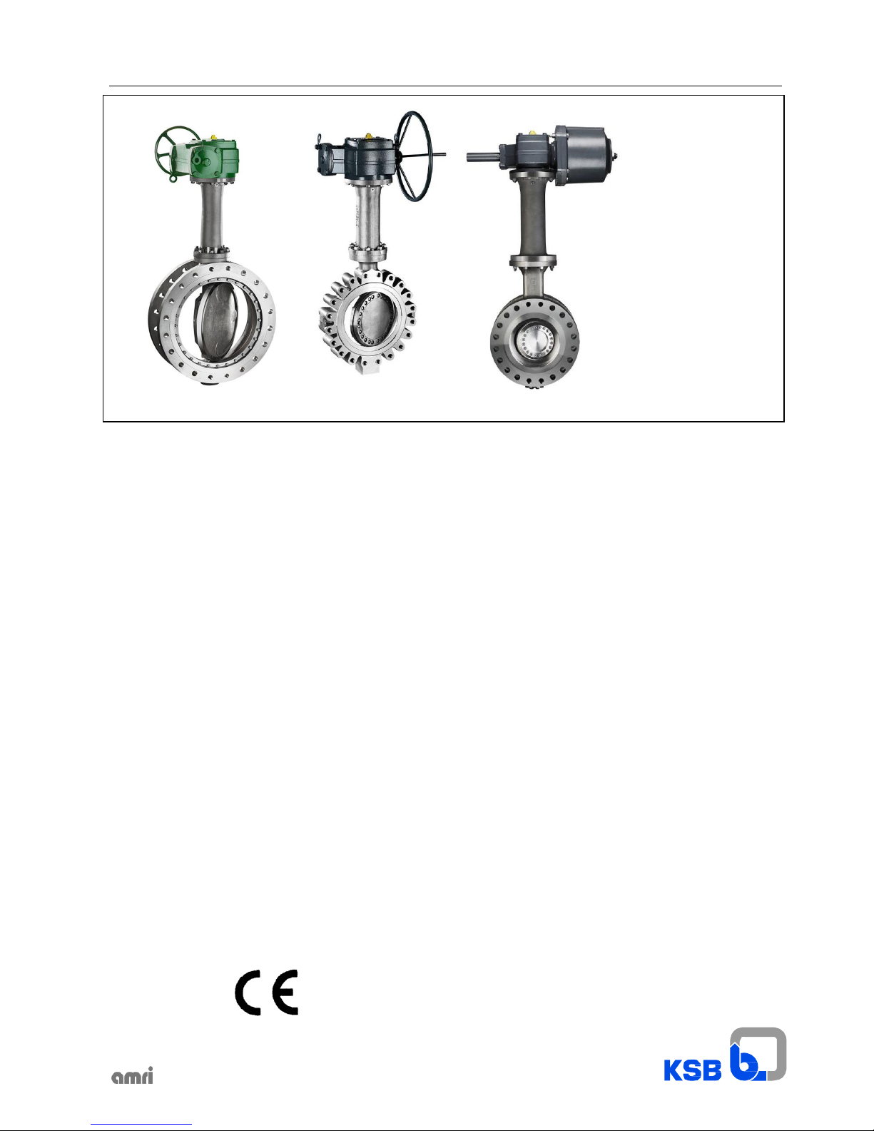
TRIODIS 150
TRIODIS 300
TRIODIS 600
TRIODIS 900
MT and TBT versions
1. Declaration of conformity 2
2. General 4
3. Safety 4
4. Transport and interim storage 5
5. Description of valves 6
6 Installation 11
7. Commissioning / Decommissionning 15
8 Maintenance / Repair 16
9. Trouble shooting 17
42810916
Page 2

2
1. Declaration of conformity
Hereby we, KSB S.A.S.
Zone industrielle Gagnaire Fonsèche
24490 LA ROCHE CHALAIS
Registered Office: 92635 - Gennevilliers
Fran
ce
declare that the valves listed below comply:
with the requirements of the Pressure Equipment Directive 2014/68/EU
Description of the valve types: Butterfly valves
- TRIODIS MT
- TRIODIS
TBT
class 150 DN 50- 600
class 300 DN 80- 1200
class 600 DN 150- 1000
class 900 DN 250- 600
class 150 DN 80- 1200
class 300 DN 80- 1200
class 600 DN 150- 1000
class 900 DN 250- 600
As per harmonized European standards: EN 12516- 1
EN 12516- 2
and other standards / directives: ASME B16.34
Suitable for: Fluids group 1 and 2
Conformity Assessment Procedure: Module H
Production sites :
LA ROCHE CHALAIS
Name and address of the notified body
for orders made from the 01/10/2011:
Bureau Veritas
67/71 boulevard du Château
92200
Neuilly- sur-
Seine
FRANCE
Notified body number: 0062
Page 3

3
with the requirements of the regulation EC REACH 1907/2006.
Regulation EC 1907/2006 on the registration, evaluation, authorization and restrictions of chemicals
Description of the valve types: Butterfly valves
-- TRIODIS MT
-- TRIODIS
TBT
class 150 DN 50 - 600
class 300 DN
80 -
1200
class 600 DN
150 -
1000
class 900 DN 250 - 600
class 150 DN 80- 1200
class 300 DN 80- 1200
class 600 DN 150- 1000
class 900 DN 250- 600
Article 33/REACH
None of substances included in the candidate list and in Annex XIV of this
regulation are present in our actuators above a concentration of 0,1%
(weight by weight)
with Directive ATEX 2014/34/EU.
Michel Delobel rev.9 - 10/16
Quality Assurance
This document was prepared electronically and is valid without signature.
Its implementation in the public domain validates his condition.
Page 4
4
2. General
These operating instructions apply to KSB offset disc butterfly valves
Design,
manufacturing
and testing of the KSB valves are subject to a
Quality Assurance System according to EN ISO 9001 and to the
European Pressure Equipment Directive 2014/68/EU (PED).
Correct installation and maintenance or repair are mandatory to
ensure trouble free operation of the valves.
The
manufacturer
cannot be made liable for these valves if operating
instructions are not being observed.
ATTENTION
The valves must not be operated beyond the limits
defined in the operating
instructions/contractual
documentation/type
leaflet. Any use beyond the above conditions will lead to overload
which the valves cannot withstand.
3.1. Safety Symbols in these Operating
Instructions
Safety instructions put forth in this instruction manual, the
nonobservance
of
which would involve the
risk of
personal injury,
they
are specially marked with the general hazard symbol:
in accordance with ISO
3864-
B.3.1.
or with the electric voltage warning sign:
Nonobservance
of this warning may lead to personal injury or
property damage, e.g.:
- Injury caused by escaping fluids (cold/hot, toxic, flammable,
corrosive or under pressure)
- Incorrect operation or destruction of the valve.
The descriptions and instructions in this manual refer to the standard
versions but also apply to the related variants.
These operating instructions do not take into consideration:
- Incidents which may occur during installation, operation and
maintenance.
- The local safety regulations. lt is the user’s responsibility to ensure
that these are also observed by the installation staff involved.
For actuated valves, the specified connection parameters and the
installation and maintenance instructions - including the operating
manual for the actuator --- must be observed.
ATTENTION
Handling a valve requires skilled and experienced
personnel.
The
personnel
in
charge
of
operation, maintenance
and
installation
of
this valve must be aware of the
interaction
between the valve and the
plant.
Operator’s errors concerning the valve may have serious
consequences for the entire plant, e.g.:
- fluid may escape
- downtime of the plant/machine
- adverse effect/reduction/increase of the efficiency/function of a
plant/machine.
For further questions or in case of damage to the valve, please
contact
your KSB Sales Office.
For further questions and supplementary orders, especially when
ordering spare parts, please always state the indications of the
marking plate.
The specifications (operating data) of the valves are listed in the
technical documentation & type leaflet of the related valve (see also
section 5).
When returning valves to the manufacturer, please refer to section 4.
3. Safety
This manual contains basic instructions to be complied with during
operation and maintenance. lt is therefore vital for the fitter and the
operator/user
to
read
this
manual before installing/commissioning
the
valve.
Also, this manual must always be available at the site where
the
valve is installed.
lt is
not enough to observe the general instructions listed in the
section
”safety”, the specific safety instructions listed in the other sections
should also be observed.
In accordance with ISO
3864-
B.3.6.
Safety
instructions
the
nonobservance
of which would
involve
hazard
to the valve and jeopardize its operation have been marked with the
word
ATTENTION
lnstructions directly attached to the valve, (e.g. nominal pressure)
must be complied with and maintained in a legible condition.
3.2. Qualification and training of personnel
The personnel for operation, maintenance, Inspection and
installation
must be adequately qualified for the work involved. The personnel
responsibility, competence and supervision must be clearly defined
by
the user. lf the personnel in question is not already in possession of
the
required know-how, appropriate training and instructions must be
provided. lf
deemed necessary, the manufacturer/supplier will
provide
such training and instructions at the user’s request. In addition, the
user is responsible for ensuring that the contents of these operating
instructions are fully understood by the personnel involved.
3.3. Danger or nonobservance of the safety
instructions
Nonobservance
of the safety instructions may lead to personal injury
and danger for both the environment and the valve itself.
Nonobservance
of these safety instructions will also forfeit the user’s
warranty.
Such noncompliance could result in for example :
- failure of essential functions of the valve/plant
- failure of prescribed maintenance and repair practices
- hazard to people by electrical, mechanical or chemical effects
-
hazard to the environment due to leakage of hazardous
substances
3.4. Safety Consciousness
The safety instructions contained in this manual, the applicable
national accident prevention regulations and any of the user’s own
applicable
internal work, operation or safety
instructions
must be fully
complied with.
3.5. Safety Instructions for the
User/Operator
Any
hot
or
cold parts
of
the valve
(e.g.
body
or
handle
or
actuator)
that
could
cause a hazard must
be
protected by the user against
accidental
contact.
Leakage of hazardous substance (e.g. flammable, corrosive, toxic,
hot) must be drained so as to avoid all danger to people or the
environment. All relevant laws must be observed.
Electrical hazards must be effectively prevented. (For details,
please refer to the IEC 364 or equivalent national standard and/or
local utility energy supply regulations).
Page 5

5
3.6. Safety lnstructions for Maintenance, Inspection and Installation work
3.6.1. General
The user is responsible for ensuring that all maintenance, inspection and installation work is carried out by authorized, adequately
qualified staff who are thoroughly familiar with this instruction manual. Any work on a valve may only be performed when the
valve is un-pressurized and has cooled down to 60 ° C or has warmed up to 0 ° C .
Any work on actuated valves may only be done after that the actuator has been disconnected from its energy supply.
The procedure described in the operating instructions to shut down the actuator must be observed. Valves in contact with
hazardous media must be decontaminated. Immediately following completion of the work, all safety relevant and protective
devices must be reinstalled and/or re-enabled. Prior to recommissioning, refer to the points listed under section 7 Commissioning.
3.6.2. End of line installation
Use as end of line and downstream dismantling is not allowed.
3.7. Unauthorized Modification and Manufacturing of Spare Parts
The equipment shall not be altered or modified in any way prior to consultation with the manufacturer. Genuine spare parts
and accessories authorized by the manufacturer will ensure operational safety. The manufacturer cannot be held responsible
for damage resulting from the use of non-genuine parts or accessories.
3.8. Inadmissible Modes of Operation
Operational safety and reliability of the valve supplied is only warranted for its designated use as defined in section 2 ”General”
of the operating instructions. The limits stated in the technical documentation must not be exceeded under any circumstances.
3.9. Draining plug
Before unscrew draining plug, pressure in the pipe should be removed.
4. Transport and Interim Storage
4.1. Transport
The valves in the as-supplied condition are ready for operation.
ATTENTION
For transport and storage, the valves must always be maintained in the semi--- closed position and be packed in
cardboard, crate or case with suitable protection (dessicant, thermowelded barrier).
ATTENTION
To prevent damage, do not hang the valve by its handle or actuator. After delivery or prior to installation,
the valve should be checked for damage during transit.
4.2. Interim Storage
The valves must be stored in such a way that correct operation is assured even after prolonged storage.
This comprises: - Storing at 5° from the closed position
- Suitable measures against contamination, frost and corrosion (e.g. by using thermowelded plastic bags with
dessicant, protection caps and plugs onto threaded holes).
Page 6
6
Type
Size (mm)
Type series booklet no.
TRIODIS 150 MT
50 - 600 8465.53
TRIODIS 300 MT
80 - 1200 8613.1783
TRIODIS 600 MT
150 - 1000
8613.1786
TRIODIS 900 MT
250- 600
-
5. Description of valves
The
sectional
drawings shown
hereafter
are
examples
for the general
design of our valves. For
drawings
and
other information pertaining
to
a specific valve series, please refer to the relevant type leaflets and
specific technical drawings.
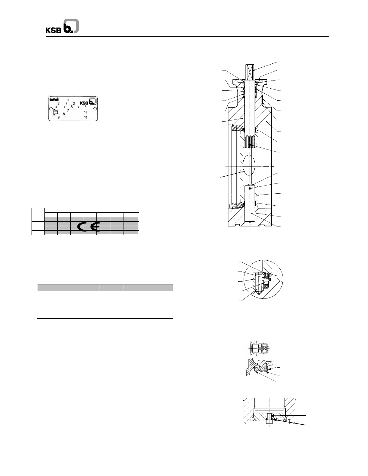
5.1. Marking
The valves are marked to PED 2014/68/EU.
Marking of the identity
plate
1 - Valve type model
2 - Internal material code
3 - Valve DN / NPS
4 - Maximum allowable pressure
5 - PS: Maximum allowable differential pressure
6 - Maximum allowable temperature
7 - Pipe flange drilling pattern (if known)
8 - Month and year of production
9 - Equipment serial number
10 - CE marking with notified body identification number
11 - Valve PN / Class designation
PS
SIZE
50
65
80
100
125
150 200
10 16
25
40
Valves for hazardous liquids and gaz (group 1) according to table 6
of annex II (PED)
559
412.1
412.3
01--- 48
553.3
310.2
Detail A
Cl. 150: DN 2” to 24”
DN 2” to 10”
213
901.1
554
310.1
412.2
561.1
970
100
543.1
561.2
903
561.3
550
543.2
310.3
210
5.2. Drawings and documents
5.2.1 MT version (average temperature)
144
50--- 5
72--- 3
50--- 6
904
Detail A
930.5
901.6
553.2
Option: Draining plug (≥8”)
41-2.3
914.3
Page 7

7
Disc drive with s
plines
Cl. 300: DN 16”
Cl. 600: DN 8” and 10”
Cl. 900: DN 10”
901.1
554.1
Detail A
901.3
930.1
Detail B
13- 21
901.6
562
Detail B
310.1
554.4
559
412.1
412.2
412.3
01- 48
553.1
Detail A
Detail C
41- 2.1
970
561
100
213
310.2
550
310.3
Detail C
Detail D
72- 3
554.2
901.2
400
144
553.2
554.3
81--- 51
914.2
176
543
41- 2.2
Detail D
Disc drive with cylindrical keys
Cl. 300: DN 18” to 36”
Cl. 600: DN 12” to 24”
Cl. 900: DN 12” to 24”
Detail B
500
901.5
901.1
554.1
13- 21
901.6
562
41- 2.1
970
561
100
213
310.2
940
550
Option: Draining Plug
Detail C
901.3
930.1
310.3
Detail D
500
901.5
41-2.3
914.3
Option : draining plug
Option : Draining Plug
Page 8

8
Type
Size (mm)
Type series booklet no.
TRIODIS TBT Class 150
80 - 1200
8465.53
TRIODIS TBT Class 300
80 - 1200
8613.1783
TRIODIS TBT Class 600
150 - 1000
8613.1786
TRIODIS TBT Class 900
250 - 600
-
5.2.2 TBT version (very low temperature)
Cl. 150: DN 8” to 42” (Buttweld Side Entry version)
Detail A
Cl. 150: DN 2” to 48” (Flanged version)
Detail A
554.2
41--- 2
Detail B
Detail C
901.1
554.1
13-
21
213
930.1
512
920
902
415.2
561.1
970
100
310.2
543.1
901.4
930.3
550
13- 21
554.2
902.2
920.2
930.2
41- 2.2
160
904
Detail B
561.1
970
213
902.1
920.1
930.1
512
41-
2.1
415.2
310.2
543.1
901.4
930.3
550
901.5
930.4
543.2
310.3
210
Detail D
Detail A
904
559
412.2
310.1
Detail B
930.4
901.5
543.2
310.3
210
559
310.1
904
01- 48
553
Detail C
Detail A
100
901.1
554.1
412.2
412.1
412.3
412.5
412.1
412.3
412.5
412.4
81--- 2 415.1
412.4
72-
3
01- 48
553
415.1
Detail B
Detail C
72--- 2
144
Detail C
930.5
901.6
553.2
Detail D
72.3
72.2
144
50.5
901.2
932
930.5
901.6
553.2
50--- 5
901.3
932
81-
2
41-2.3
914.3
Option : Draining Plug
Option : Draining Plug
Option : Draining Plug
Page 9

Disc drive with s
plines
Cl. 300: DN 16”
Cl. 600: DN 8” and 10”
Cl. 900: DN 10”
901.1
554.1
904
Detail A
Detail B
Detail C
Detail D
901.3
930.1
310.1
554.4
412.2
412.1
559
412.3
412.5
412.4
01--- 48
553.1
415.1
72--- 3
554.2
901.2
400
144
553.2
554.3
81--- 51
914.2
176
543
41--- 2.2
Detail B
Detail A
Detail C
Detail D
Disc drive with cylindrical keys
Cl. 300: DN 18” to 36”
Cl. 600: DN 12” to 24”
Cl. 900: DN 12” to 24”
Detail B
Detail C
Detail D
13--- 21
930.2
902
920
562
41---
2.1
415.2
554.5
970
561
100
213
310.2
550
310.3
500
901.5
932
901.1
554.1
13--- 21
930.2
902
920
41--- 2.1
562
415.2
554.5
970
561
100
213
310.2
940
550
901.3
930.1
310.3
500
901.5
932
9
Option : Draining Plug
Option: Draining Plug
41-2.3
914.3
Option : Draining Plug
Page 10

10
Part No.
Name of Parts
01- 48
Sealing packing
100
Body
13- 21
Extension
144
Seat
160
Cover
176
Bottom
210
Lower shaft for DN>12”
213
Shaft
310.1
Self-lubricating strip
310.2
Upper bearing
310.3
Lower bearing
400
Spiral Wound Gasket
41- 2
Static joint
41- 2.1
Extension static joint
41- 2.2
Bottom static joint
41-2.3
Draining plug screw
412.1 / 412.2
O--- Ring
412.3 / 412.4
O--- Ring
412.5
O--- Ring
415.1 / 415.2
Lip Seal Ring
50- 5
Reaction ring
500
Anti-static device
512
Adjusting ring
543
Spacer bush
543.1 / 543.2
Spacer bush
550
Disc
553
Thrust insert
553.1
Upper thrust insert
553.2
Thrust insert
554.1
Upper washer
554.2
Nord Lock washer
554.3
Nord Lock washer
554.4 / 554.5
Spacer
559
Gasket holder
561 / 561.1
Grooved nail
562
Pin
72- 2
Centering flange
72- 3
Tightening flange
81.2
Wire
81- 51
Tightening part
901.1 / 901.2
Hexagon screw
901.3 / 901.4
Liaison screw
901.5 / 901.6
Hexagon screw
902
Stud bolt
902.1 / 902.2
Stud
904
Socket screw
914.2
Hexagon socket head cap screw
914.3
Static gasket
920
Hexagon nut
920.1 / 920.2
Hexagon nut
930.1 / 930.2
Liaison screw retainer
930.3 / 930.4
Nut lock
930.5
Retainer
932
Lock washer
940
Cylindrical key
970
Identity plate
5.3. List of Components
Some parts does not exist for all versions
Parts list for MT version
Parts list for TBT version
Part No.
Name of Parts
01- 48
Sealing packing
100
Body
13- 21
Extension
144
Seat
176
Bottom
210
Shaft
213
Operating shaft
310.1
Plain bearing
310.2
Upper bearing
310.3
Lower bearing
400
Spiral Wound Gasket
41- 2.1
Extension static joint
41- 2.2
Bottom static joint
412.1
O--- Ring
412.2
O--- Ring
412.3
O--- Ring
41-2.3
Draining plug screw
500
Antistatic device
50.5
Reaction ring
50.6
Tightening ring
543
Spacer bush
543.1 / 543.2
Spacer bush
550
Disc
553.1
Upper thrust insert
553.2 / 553.3
Thrust insert
554
Washer
554.1
Upper washer
554.2
Washer
554.3
Washer
554.4
Spacer
559
Gasket holder
561
Grooved nail
561.1
Grooved nail
561.2 / 561.3
Grooved pin
562
Pin
72--- 3
Tightening flange
81- 51
Tightening part
901.1 / 901.2
Hexagon screw
901.4
Liaison screw
901.5 / 901.6
Hexagon screw
903
Threaded screw
904
Grub screw
914.2
Hexagon socket head cap screw
914.3
Static gasket
930.1
Liaison screw retainer
970
Identity plate
Page 11

11
5.4. Functioning principle TRIODIS 150
Description
The
valve consists mainly
of a
body (100), operating
shaft
(213),
shaft
(210) and disc (550).
Disc---
shaft connection: The operating shaft (213) is connected to
the disc (550) by grooved pins, splines or taper pins.
Shaft seal area:
MT: realized by elastomer O- Ring (412) fitted into a gasket holder
(559). Fire safety is achieved by a graphite packing
(01-
48) tightened
by the gasket holder (559), screws (901.1) and washers (554).
TBT: realized by elastomer O- Ring (412) fitted into a gasket holder
(559). Fire safety is
achieved
by a
graphite packing (01-
48) tightened
by
the gasket holder (559), screws (901.1) and washers (554). Lip
seal
ring (415.1) tightened by the gasket holder (559), the sealing packing
(01-
48), screws (901.1) and washers (554).
Flow seal area:
MT and TBT: the seat (144) is tightened in the body (100) by a
tightening
flange
(72---
2)
which
is
maintained
by
radial screws (904)
or
axial screws (901).
MT flanged type: the seat (144) is tightened in the body (100) by a
tightening
flange
(72-
2)
which
is
maintained
by
radial screws (904)
or
axial screws (901).
Bonnet seal area:
TBT: It is made by a metallic seal
(41-
2) tightened by the extension
(13-
21), studs (902) and nuts (920).
The compression of the seating disc edge out of the seat is achieved
by triple eccentric kinematics.
The axis of the shafts and disc is offset to valve axis and eccentric to
pipe axis.
Operation: The valves are
quarter---
turn operated manually by
handles or gear box or hydraulic, pneumatic and electric actuators
bolted on the valve top plate (as per ISO 5211 standard).
5.5. Functioning principle TRIODIS 300/600/900
Description
The valve consists mainly of a body (100), operating shaft (213), disc
(550) and a seat (144)
Disc---
shaft connection: The operating shaft (213) is connected to
the disc (550) by a liaison screw or splines or cylindrical keys.
Stem seal area:
TBT: Realized by elastomer O- Ring (412) fitted into a gasket holder
(559). Fire safety is
achieved
by a
graphite packing (01-
48) tightened
by
the gasket holder (559), screws (901.1) and washers (554). Lip
seal
ring (415.1) tightened by the gasket holder (559), the sealing packing
(01-
48), screws (901.1) and washers (554).
Flow seal area:
Tightness between disc (550) and body (100) is done by the seat
6. Installation
6.1. General
ATTENTION
To avoid leakage, deformation or rupture of the body,
the piping should be laid out in such a way that no thrust or bending
forces act on the valve bodies (100) when they are installed and
operational.
ATTENTION
The sealing faces of the flanges must be clean and
undamaged.
It is mandatory to add gaskets between body and piping
flanges. To insert the valve between flanges, pull apart the two pipes
flanges to obtain sufficient clearance between valves flanges and
piping flanges. All holes provided in the flanges must be used for the
flange connection (does not apply for buttweld type valves).
lf construction work is still in progress,
non---
mounted valves
must be
protected
against dust, sand and building
material
etc.(cover
with suitable means).
Do not use gear handwheels as footholds!
Valves and pipes used for high (> 60 ° C) or low (< 0 ° C)
temperatures must either be fitted with a protective insulation, or
there
must be warning signs fitted showing that it is dangerous to touch
these valves.
lf a valve is used as end-valve in a pipe, this valve should be
protected against unauthorized or unintentional opening to prevent
personal injury or damage to property.
To guarantee a good operation of the valves at temperatures
< 0 ° C it is
necessary to eliminate all the water (steam or liquid)
inside
the piping to avoid freezing at the seat gasket or lower shaft level.
6.2. Installation conditions
6.2.1. Recommended minimum distances between the
position of the valve and of the
T---
piece or elbow.
(144). Tightness between seat (144) and disc (550) is done by a
static gasket (400).
Dynamic
seat (144) and static gasket (400) are
maintained
on disc by a tightening flange
(72-
3) and screw (901.2).
The contact pressure between seat and body is guaranteed by triple
offset cinematic and torque of actuator.
Bonnet seal area:
It is made by an extended graphite seal
(41---
21) tightened by
the extension
(13-
21), studs (902) and nuts (920).
Operation: The valves are
quarter---
turn operated manually by gear
box, hydraulic, pneumatic and electric actuators bolted on the valve
top plate (as per ISO 5211 standard).
Also valid for valve placed at pump discharge
1 Ø
5-6 Ø Ø 1 Ø
2-3 Ø
Ø
Ø
1 Ø
Ø
Ø
2-3 Ø
2-3 Ø
1 Ø
Ø
Page 12

12
6.2.2. Flanging dimensions
6.2.2.1. An n u l a r (T1) &
Full---
lug type body (T4) - Class 150 / 300 / 600
Connection to the piping.
Piping flanges must match the following dimensions.
e1: min. allowable diameter on upstream flange face
e3: min. allowable diameter on downstream flange face
MT and TBT version / Class 150
Size
NPS
Disc clearance
e1
e2
e3
e4
50 2 36 9 - - 65
2 1/2
49
13
13 1 80 3 62
18
38 6 100 4 81
24
67
17
125 5 103
33
91
23
150 6 131
48
117
33
200 8 177
70
163
51
250
10
226
91
212
70
300
12
266
106
254
87
350
14
309
123
297
103
400
16
360
145
346
121
450
18
420
169
408
147
500
20
456
182
444
160
600
24
546
213
537
197
MT and TBT version / Class 300
Size
NPS
Disc clearance
e1
e2
e3
e4
80 3 65
20
64
15
100 4 92
30
90
25
150 6 145
50
135
40
200 8 190
70
180
60
250
10
235
90
225
75
300
12
280
110
270
90
350
14
330
125
320
110
400
16
370
135
360
125
450
18
420
155
415
150
500
20
475
180
465
160
550
22
515
190
510
180
600
24
565
215
560
200
MT and TBT version / Class 600
Size
NPS
Disc clearance
e1
e2
e3
e4
150 6 140
50
130
40
200 8 185
60
180
50
250
10
225
75
220
65
300
12
265
85
260
75
350
14
305
100
300
90
400
16
355
115
350
105
450
18
400
130
395
120
500
20
445
145
435
130
600
24
555
190
545
175
6.2.2.2. Flanged type body (T7) Class 150 / 300 / 600 / 900
Connection to the piping.
Piping flanges must match the following dimensions.
e1: min. allowable diameter on upstream flange face
e3: min. allowable diameter on downstream flange face
MT version / Class 150
Size
NPS
Disc clearance
e1
e2
e3
e4
50 2 - - - - 65
2½
- - -
-
80 3 - - 18
2
100 4 - - 52
8
125 5 - - 81
17
150 6 - - 112
29
200 8 - - 158
46
250
10
27 1 208
65
300
12
214
52
197
42
350
14
263
70
245
58
400
16
306
82
289
70
450
18
376
111
359
97
500
20
417
128
399
112
600
24
505
157
487
141
TBT version / Class 150
Size
NPS
Disc clearance
e1
e2
e3
e4
80 3 - - 18 2 100 4 - - 52 8 125 5 - - 81
17
150 6 - - 112
29
200 8 153
33
102
17
250
10
211
52
160
33
300
12
256
68
204
47
350
14
308
87
251
63
400
16
357
101
294
75
450
18
418
126
361
101
500
20
466
146
402
117
550
22
508
154
437
123
600
24
551
173
490
146
650
26
537
139
524
155
700
28
566
142
559
170
750
30
702
235
614
194
800
32
745
246
655
205
900
36
858
295
765
252
1000
40
918
298
829
258
1050
42
960
303
902
306
1200
48
1041
309
1019
358
Page 13

13
MT and TBT version / Class 300
MT and TBT version / Class 600
Size
NPS
Disc clearance
e1
e2
e3
e4
150 6 0 0 0
0
200 8 0 0 0
0
250
10
50 5 0
0
300
12
130
20
100
10
350
14
185
30
160
20
400
16
255
50
235
40
450
18
305
65
285
55
500
20
350
75
335
65
600
24
460
110
445
100
700
28
470
110
450
100
750
30
535
135
515
120
800
32
560
140
540
120
900
36
630
160
610
140
1000
40
720
185
700
170
MT and TBT version / Class 900
Size
NPS
Disc clearance
e1
e2
e3
e4
250
10 - - - -
300
12 - - - -
350
14 - - - -
400
16 - - - -
450
18 * * * *
500
20
200
20
120
10
600
24
340
50
300
35
* Please consult us
6.2.3. Flange gasket
The
dimensional compatibility
of the flange gasket must be
checked
to ensure the connection quality, according to the dimensions
defined hereunder:
6.2.3.1. MT and TBT versions / Class 150 / 300 / 600 / 900
Annular (T1) & Full--- lug
type body (T4)
Flanged
Type body --- Type 7
Class 150
Class 300 / 600 / 900
MT and TBT version / Class 150
Size
NPS
Type 1/4/7
Ø1
Ø2
Ø3
50 2 91.9
62
73
65
2½
104.6
74
91
80 3 127
90
106
100 4 157.2
117
128
125 5 185.7
142
148
150
6
215.9
168
173
200
8
269.7
219
226
250
10
323.9
273
274
300
12
381
327
331
350
14
412.8
363
386
400
16
469.9
414
438
450
18
533.4
468
498
500
20
584.2
518
538
550
22
*
*
*
600
24
692.2
623
644
650
26
* * *
700
28
800
705
705
750
30
* * *
800
32
* * *
850
34
* * *
900
36
* * *
1000
40
* * *
1050
42
* * *
1200
48
* * *
* Please consult us
Size
NPS
Disc clearance
e1
e2
e3
e4
80 3 0 0 0
0
100 4 0 0 0
0
150 6 50 0 0
0
200 8 130
25
135
25
250
10
185
45
195
45
300
12
230
60
245
60
350
14
295
80
305
80
400
16
330
90
340
90
450
18
390
115
400
115
500
20
445
140
460
140
550
22
475
145
470
135
600
24
535
175
530
160
700
28
615
200
610
185
750
30
655
210
650
200
800
32
715
240
705
225
900
36
795
270
820
270
1000
40
845
275
830
265
1200
48
1025
340
1010
320
Page 14

14
MT and TBT version / Class 300
Size
NPS
Design
Type 7
Type 4
Ø1
Ø2
Ø1
Ø2
80
3
ASME B16.5
127
90
127
90
EN 1092 PN40
138
127
100
4
ASME B16.5
157.2
115.5
158
115.5
EN 1092 PN40
162
158
150
6
ASME B16.5
216
171.5
216
171.5
EN 1092 PN40
218
218
200
8
ASME B16.5
270
222
270
222
EN 1092 PN40
285
285
250
10
ASME B16.5
324
277
324
277
EN 1092 PN40
345
345
300
12
ASME B16.5
381
329
381
329
EN 1092 PN40
410
410
350
14
ASME B16.5
413
367
413
367
EN 1092 PN40
465
465
400
16
ASME B16.5
470
416
470
416
EN 1092 PN40
535
535
450
18
ASME B16.5
533.5
464
533.5
464
EN 1092 PN40
560
560
500
20
ASME B16.5
584
521.5
584
521.5
EN 1092 PN40
615
615
550
22
ISO 2084 PN40
641
553
-
-
ISO 7005 PN50
641
-
600
24
ASME B16. 5
692
622
692
622
EN 1092 PN40
735
735
700
28
ASME B16.47- A
800
717
ASME B16.47- B
787
750
30
ASME B16.47- A
857
768
ASME B16.47- B
845
800
32
ASME B16.47- A
914
820
ASME B16.47- B
902
900
36
ASME B16.47- A
1022
920
ASME B16.47- B
1010
1000
40
ASME B16.47- A
1086
980
ASME B16.47- B
1114
1050
42
ASME B16.47- A
1137
1035
ASME B16.47- B
1168
1200
48
ASME B16.47- A
1302
1180
ASME B16.47- B
1327
MT and TBT version / Class 600
Size
NPS
Design
Type 7
Type 4
Ø1
Ø2
Ø1
Ø2
150 6 ASME B16.5
216
170.5
216
170.5
200 8 ASME B16.5
270
222
270
222
250
10
ASME B16.5
324
268
324
268
300
12
ASME B16.5
381
323
381
323
350
14
ASME B16.5
413
357
413
357
400
16
ASME B16.5
470
406
470
406
450
18
ASME B16.5
533.5
464
533.5
464
500
20
ASME B16.5
584.5
517
584
517
600
24
ASME B16.5
692.5
622
692
622
700
28
ASME B16.47- A
800
681
ASME B16.47- B
784
750
30
ASME B16.47- A
857
751
ASME B16.47- B
841
800
32
ASME B16.47- A
914
767
ASME B16.47- B
895
900
36
ASME B16.47- A
1022
905
ASME B16.47- B
1010
1000
40
ASME B16.47- A
1111
941
MT and TBT version / Class 900
Size
NPS
Design
Type 7
Ø1
Ø2
250
10
ASME B16.5
324
268
300
12
ASME B16.5
381
323
350
14
ASME B16.5
413
357
400
16
ASME B16.5
470
406
500
20
ASME B16.5
584.5
517
600
24
ASME B16.5
692.5
622
6.2.4. Bolting
Length of bolting are defined in Type series booklet. KSB
recommends :
to follow this length in order to maximize threaded
length.
For A2 bolts (shaft location), to apply an adapted
tightening torque as a function of state of art
(threading length, material of the bolt, etc …)
Page 15

15
6.3. Handling
Handling means may be necessary to install large sizes
valves.
Handle only when parts are at ambient temperature
Use only lifting rings delivered by KSB (lifting lugs
paints according to DIN 580 not allowed)
They must be used as shown.
BWSE
Horizontal Vertical
T7
T4
6.4. Recommendations for installation
The lug and flanged valves have to be inserted lightly between
flanges with flange gaskets.
Before assembly
- Verify that the cone on body and the seat are free of solid
particles
like chips, packing material, etc...
- Verify that pipeline flanges are located on the same centerline
and are parallel.
- Verify that dimensions of gaskets flange are compatible with
the dimensions mentioned in the table 6.2.3.
- Verify that nothing hinders the complete moving of the disc
during opening or closing.
- Pull apart the pipeline flanges to allow valve and gaskets
insertion.
During assembly
- Place the disc in closed position.
-
Position the valve above the pipe and place gasket in contact of
each flat face (you can fix them with a spot of glue).
- Insert valve and gaskets between pipe flanges and center
using several tie--- rods.
- Screw up progressively the nuts until metal complete tightness is
achieved between
the valve body, the pipeline flanges and
gaskets. Note: Respect maximum torque (See paragraph 6.2.4).
- Operate the valve several times to ensure that there is no valve
disc obstruction.
- During transport, the valve may have been subjected to
important temperature differences or the vibrations making it
necessary to retighten the assembly. Before performing this
operation, please read the maintenance manual.
6.5. Actuated valves
Actuator bumpers are adjust in KSB factory.
Do not modify the adjusting to preserve gasket.
Electrical cables may only be connected by qualified
personnel.
The applicable electrical regulations (e.g. IEC and national
standards), also for equipment in hazardous locations, must be
observed. All electrical equipment such as actuator, switchboard,
magnetic valve drive, limit switch etc. must be installed in flood
proof dry
locations. Voltage
and frequency must match the valves
stated on the identity plate.
The seat (144) and the disc edge shall be protected against
the metallic projections resulting from welding or grinding.
If the valve is used with a non irreversible actuator, it is necessary
to maintain alimentation of actuator to guaranty tightness
performance.
Page 16

16
7. Commissioning/Decommissioning
7.1. Commissioning
7.1.1. General
Prior to commissioning the valve, the pressure, temperature
and material data stated on the valve should be compared to the
actual operating conditions in the piping system to check whether
the valve can withstand the loads occurring in the system.
Possible pressure surges (water hammer) must not be
exceed
the highest admissible pressure. Adequate precautions should be
taken. In new pipe systems and especially after repair work, the
system should be flushed with the valves fully open to remove
solids, e.g. weld beads, which may damage the seats.
7.1.2. Operation
The
position
of the disc is
indicated
by the
pointer
of the
actuator
or
by handle lever. The valves are closed by turning in the clockwise
direction (top view) and opened in the counterclockwise direction.
7.1.3. Functional Check
The following functions should be checked before commissioning,
the shut-off-function of the valves should be checked by repeated
opening and closing.
7.1.4. Actuated valves
Adjustable end stops and torque limiter of actuators have been
adjusted in factory.
7.2. Decommissioning
During extended shutdown periods, liquids liable to change their
condition
due to polymerization, crystallization, solidification etc.
must be drained from the piping system. If necessary, the piping
system should be flushed with the valves fully open.
8. Maintenance/Repair
8.1. Safety Instructions
Maintenance and repair work may only be carried out by skilled
and qualified personnel.
For all maintenance and repair work, the safety instructions listed
below and also the general notes in section 2 must be observed.
Always use suitable spare parts and tools, even in case of
emergency, otherwise correct operation of the valves cannot be
assured.
8.2. Valve removal from piping and
actuator disconnecting
Identify the valve by identity plate.
Please check what is the relevant spare kit. Place the disc
in closing position
The entire valve must be unpressurized and must have
cooled down sufficiently so that the temperature of the medium is
lower than 60 ° C, to prevent scalding or warmed so that the
temperature is higher than 0 ° C.
Opening pressurized valves will cause danger to life and
limb! lf toxic or highly flammable substances or liquids whose
residues may cause corrosion by interaction with the air humidity
were handled by the valve, then the valve should be drained and
flushed or vented. lf necessary, wear safety clothing and a face
guard/mask. Depending on the installation position, any liquid
remaining in the valve may have to be removed.
Prior to possible transport, the valves must be flushed and drained
carefully. lf you have any questions please contact your KSB
Sales Office.
lf actuators powered by an external source of energy
(electric, pneumatic, hydraulic) need to be removed from the
valves or dismantled, the energy supply must be shut down prior
to starting any repair work.
Remove the valve from the piping with its actuator. Identify
the mounting position of the actuator
Disconnect the actuator and take care of all bolting parts.
8.3. Spares
Use the relevant spare parts included in the kits. Please refer to
the manual maintenance.
All constitutive parts of kit and flange gaskets must be replaced.
During the mounting /dismantling of the valve, the
operations must be respected step by step to prevent injuries and
material damages.
During the tests, closing and opening valves, care must be taken
that no operator interferes with the disc travel.
8.4. Valve disassembly and
re---
assembly
See manual of maintenance reference:
Manual of maintenance Reference
Maintenance leaflet TRIODIS 150 8460.81/5- 10
Maintenance leaflet TRIODIS 8465.81/1- 10
300- 600- 900
8.5. Draining plug
Before unscrew draining plug, pressure in the pipe should be
removed. In order to prevent unwished lost of screw, apply glue at
each reassembly.
Page 17

17
9 Troubleshooting
9.1 General
All repair and service work must be carried out by qualified personnel using suitable tools and genuine spare parts.
The previous safety instructions must be observed.
9.2 Faults & Remedies
Leakage at interference
body-
bottom
Leakage at interference
body-
extension
Downstream/Upstream leakage
Shaft leakage
Flange leakage
Over torque
No opening
No closing
Hard point
Vibration / Fluttering
Foreign particles in the valve
Actuator on safe position
- Open the valve, line without fluid or flow, remove the particle
- inspect seal/disc
- replace seal/disc
Broken body
Defect due to water hammer
Search for the reasons.
Replace / Repair the valve
Broken or warped disc
Defect due to water hammer
Search the reasons. Replace / Repair the valve
Damaged disc, corroded disc
Repair the valve - Replacement of seal
Broken shaft, twisted shaft
Analyze the defect / research of causes / replace shaft
Wrong flange gasket
Check type and dimensions
Wrong flanging
Check type and flange bolting torque
Wrong flanging size
Follow instructions given in KSB technical leaflet
Wrong face to face,
non-parallel flanges
Flanging has to be modified in accordance with KSB technical leaflet
requirements.
Flow conditions
Wrong operating conditions
Check the technical offer versus service conditions
Damaged actuator
Check sizing versus operating conditions (see KSB)
Defective sealing
Search the reasons
Tighten or replace sealing packing 01- 48
Replace O- rings 412.1 to 412.5
Defective sealing
Actuator on safe position
Open the valve line without fluid or flow ( 0° C < temperature < 60° C)
Search the reasons by inspecting parts
Repair sealing surface if necessary
Replace graphite static joint 41- 2.1.
Defective sealing
Search the reasons
Replace graphite static joint 41- 2.2
Retighten screws of bottom.
Page 18

18
Notes
Page 19

19
Notes
Page 20

20
Legal
information/Copy
right
-
-
-
Original
operating
manual
-
-
-
all right
reserved Contents
provided herein
must neither
be processed
without
KSB’express
written
consent Subject
to
technical
modification without
prior
notice.
8613.81/
7
-
-
-
EN
09.02.17
TRIODIS 150 / 300 / 600 / 900
KSB S.A.S.
4, allée des Barbanniers 92635 Gennevilliers Cedex (France)
Tel.: +33 1 41 47 75 00 Fax: +33 1 41 47 75 10 www.ksb.com
 Loading...