

KSB STAAL 40 AKD, STAAL 100 AKGS-A, STAAL 100 ZTS, STAAL 40 AKKS, STAAL 100 AKK Operating Manual
...Page 1

STAAL 40 AKD/AKDS, STAAL 100 AKD/AKDS,
AKG-A/AKGS-A, ZTS,
STAAL 40 AKK/AKKS, STAAL 100 AKK/AKKS,
AKR/AKRS, ZRS, VTS, UGS
Operating Manual
Page 2

Legal information/Copyright
Operating Manual
Original operating manual
All rights reserved. The contents provided herein must neither be distributed, copied, reproduced,
edited or processed for any other purpose, nor otherwise transmitted, published or made available to a
third party without the manufacturer's express written consent.
Subject to technical modification without prior notice.
© KSB SE & Co. KGaA, Frankenthal 04/10/2018
Page 3

Contents
3 of 68
Contents
Glossary .................................................................................................................................................. 5
1 General.................................................................................................................................................... 6
1.1 Principles ...........................................................................................................................................................6
1.2 Target group.....................................................................................................................................................6
1.3 Other applicable documents............................................................................................................................6
1.4 Symbols .............................................................................................................................................................6
2 Safety...................................................................................................................................................... 7
2.1 Key to safety symbols/markings.......................................................................................................................7
2.2 General..............................................................................................................................................................7
2.3 Intended use .....................................................................................................................................................8
2.3.1 Prevention of foreseeable misuse.......................................................................................................8
2.4 Personnel qualification and training...............................................................................................................8
2.5 Consequences and risks caused by non-compliance with this manual .........................................................8
2.6 Safety awareness ..............................................................................................................................................9
2.7 Safety information for the operator/user.......................................................................................................9
2.8 Safety information for maintenance, inspection and installation ................................................................9
2.9 Unauthorised modes of operation..................................................................................................................9
3 Transport/Temporary Storage/Disposal............................................................................................. 11
3.1 Checking the condition upon delivery..........................................................................................................11
3.2 Transport.........................................................................................................................................................11
3.3 Storage/preservation......................................................................................................................................12
3.4 Return to supplier...........................................................................................................................................13
3.5 Disposal ...........................................................................................................................................................13
4 Valve Description ................................................................................................................................. 14
4.1 General description ........................................................................................................................................14
4.2 Marking...........................................................................................................................................................14
4.3 Gate Valves .....................................................................................................................................................14
4.3.1 Function of gate valves with bolted bonnet....................................................................................14
4.3.2 Function of gate valves with pressure seal bonnet .........................................................................15
4.3.3 Gate Valves to DIN/EN with Bolted Bonnet .....................................................................................16
4.3.4 Gate Valves to DIN/EN in Pressure Seal Design ................................................................................23
4.4 Body Pressure Relief Valve.............................................................................................................................29
4.4.1 UGS .....................................................................................................................................................29
4.5 Swing check valves .........................................................................................................................................33
4.5.1 Function of swing check valves with bolted cover ..........................................................................33
4.5.2 Function of swing check valves with pressure seal cover ................................................................33
4.5.3 Swing Check Valves with Bolted Cover ............................................................................................34
4.5.4 Swing check valves with pressure seal cover....................................................................................39
4.6 Line Blind Valve ..............................................................................................................................................45
4.6.1 VTS ......................................................................................................................................................45
4.7 Scope of supply...............................................................................................................................................48
4.8 Dimensions and weights ................................................................................................................................48
5 Installation at Site................................................................................................................................ 49
5.1 General information/Safety regulations .......................................................................................................49
5.2 Installation position and location..................................................................................................................50
5.3 Welding into the pipeline..............................................................................................................................51
5.4 Valves with actuator.......................................................................................................................................52
5.5 Insulation ........................................................................................................................................................53
5.6 Body pressure relief valve ..............................................................................................................................54
6 Commissioning/Start-up/Shutdown................................................................................................... 57
6.1 Commissioning/Start-up.................................................................................................................................57
6.1.1 Prerequisites for commissioning/start-up .........................................................................................57
Page 4

Contents
4 of 68
6.1.2 Valve actuation ..................................................................................................................................59
6.1.3 Information on the mechanical components...................................................................................60
6.2 Shutdown........................................................................................................................................................62
6.2.1 Measures to be taken for shutdown ................................................................................................62
6.2.2 Servicing/Maintenance ......................................................................................................................62
7 Servicing/Maintenance........................................................................................................................ 64
7.1 Safety regulations...........................................................................................................................................64
8 Trouble-shooting.................................................................................................................................. 65
9 EU Declaration of Conformity............................................................................................................. 66
9.1 EU Declaration of Conformity for STAAL40, STAAL100, AKG-A/AKGS-A, AKR/AKRS, ZTS, ZRS, VTS ......66
Index ..................................................................................................................................................... 67
Page 5

Glossary
5 of 68
Glossary
Pressure Equipment Directive (PED)
The 2014/68/EU Directive sets out the
requirements to be met by pressure equipment
intended to be placed on the market in the
European economic area.
Technical literature
Refer to the product catalogue for the technical
literature on our products at www.ksb.com.
Page 6
1 General
6 of 68
1 General
1.1 Principles
This operating manual is supplied as an integral part of the type series and variants
indicated on the front cover.
The manual describes the proper and safe use of this equipment in all phases of
operation.
In the event of damage, immediately contact your nearest KSB sales organisation
responsible to maintain the right to claim under warranty.
1.2 Target group
This operating manual is aimed at the target group of trained and qualified specialist
technical personnel.
1.3 Other applicable documents
Table1: Overview of other applicable documents
Document Contents
Type series booklet Description of the valve
Flow characteristics
1)
Information on Kv and zeta values
General assembly drawing
2)
Sectional drawing of the valve
Sub-supplier product literature3)Operating manuals and other product literature
for the accessories
Observe the relevant manufacturer's product literature for the accessories.
1.4 Symbols
Table2: Symbols used in this manual
Symbol Description
✓ Conditions which need to be fulfilled before proceeding with the
step-by-step instructions
⊳ Safety instructions
⇨
Result of an action
⇨ Cross-references
1.
2.
Step-by-step instructions
Note
Recommendations and important information on how to handle
the product
1) If any
2) If inclusion in the scope of supply has been agreed; otherwise refer to the type series booklet.
3) If inclusion in the scope of supply has been agreed.
Page 7
2 Safety
7 of 68
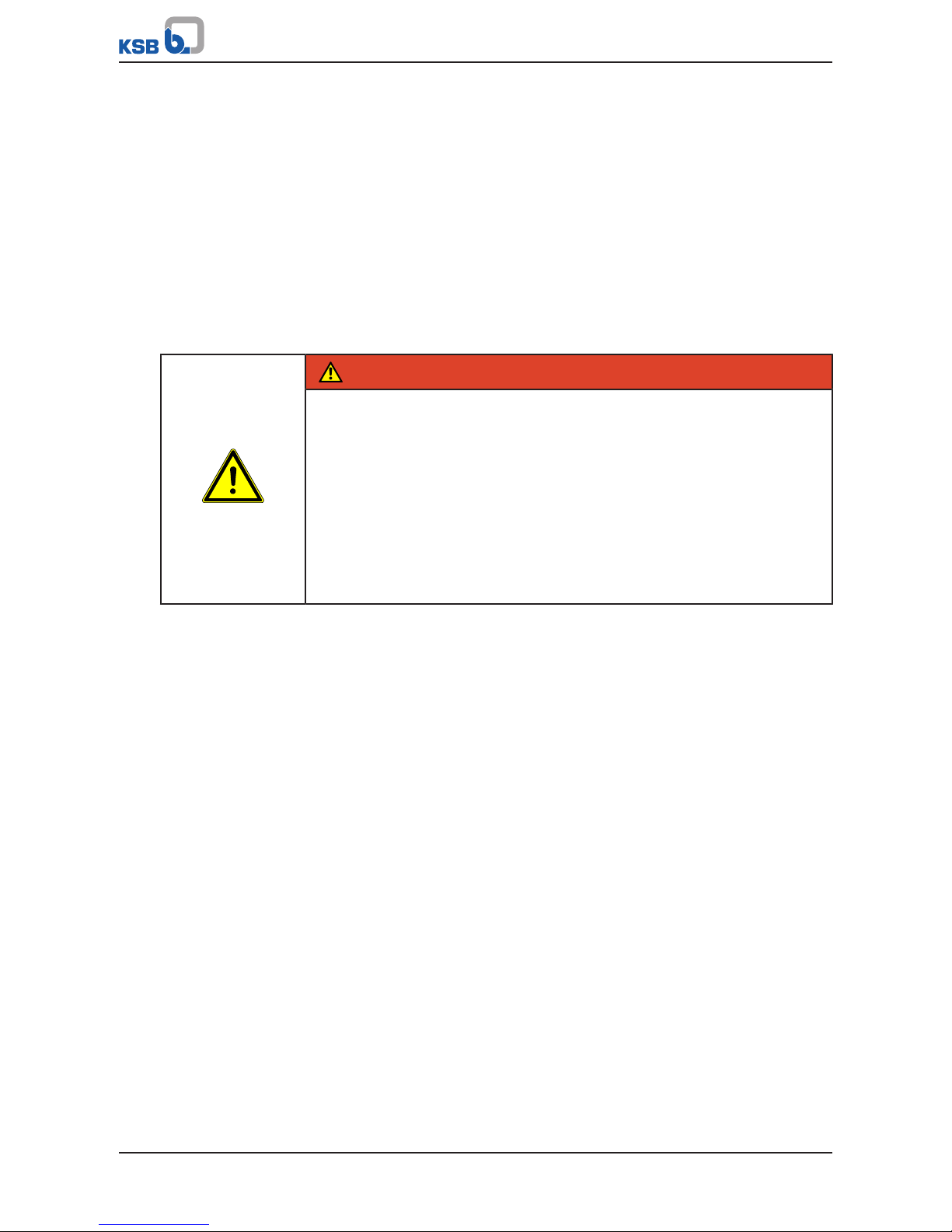
2 Safety
!
DANGER
All the information contained in this section refers to hazardous situations.
In addition to the present general safety information the action-related safety
information given in the other sections must be observed.
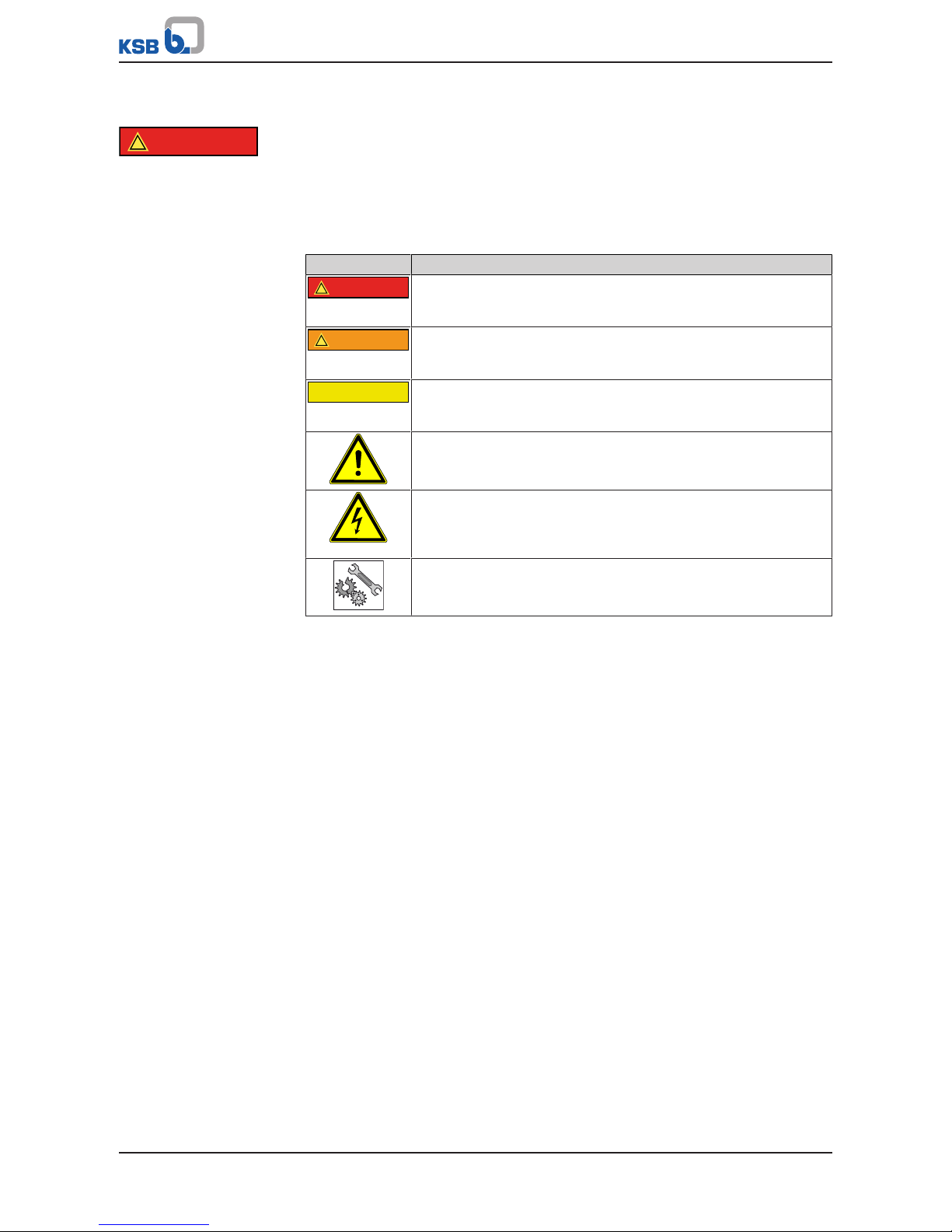
2.1 Key to safety symbols/markings
Table3: Definition of safety symbols/markings
Symbol Description
!
DANGER
DANGER
This signal word indicates a high-risk hazard which, if not avoided,
will result in death or serious injury.
!
WARNING
WARNING
This signal word indicates a medium-risk hazard which, if not
avoided, could result in death or serious injury.
CAUTION
CAUTION
This signal word indicates a hazard which, if not avoided, could
result in damage to the machine and its functions.
General hazard
In conjunction with one of the signal words this symbol indicates a
hazard which will or could result in death or serious injury.
Electrical hazard
In conjunction with one of the signal words this symbol indicates a
hazard involving electrical voltage and identifies information about
protection against electrical voltage.
Machine damage
In conjunction with the signal word CAUTION this symbol indicates
a hazard for the machine and its functions.
2.2 General
This operating manual contains general installation, operating and maintenance
instructions that must be observed to ensure safe operation of the system and
prevent personal injury and damage to property.
The safety information in all sections of this manual must be complied with.
The operating manual must be read and understood by the responsible specialist
personnel/operators prior to installation and commissioning.
The contents of this operating manual must be available to the specialist personnel
at the site at all times.
Information and markings attached directly to the product must always be complied
with and kept in a perfectly legible condition at all times. This applies to, for
example:
▪ Flow direction arrow
▪ Manufacturer
▪ Type designation
▪ Nominal pressure, nominal size
▪ Year of construction
▪ Body material
The operator is responsible for ensuring compliance with all local regulations not
taken into account in this operating manual.
The design, manufacture and the testing of the valve are subject to a QM system to
DINENISO9001 as well as the current European Pressure Equipment Directive.
European Pressure Equipment Directive (PED) Compliance with these requirements,
however, is based on normal, predominantly static loading.
Page 8

2 Safety
8 of 68
Bear in mind that valves exposed to creep-rupture conditions have a limited service
life and have to meet the applicable regulations stipulated in the technical codes.
In the case of customised special variants, further restrictions may apply with regard
to the operating mode and service life. Refer to the relevant sales documentation for
applicable limitations.
This operating manual does not take into account:
▪ Any eventualities or incidents occurring during installation performed by the
customer, operation and maintenance.
▪ Local regulations; the operator must ensure that such regulations are strictly
observed by all, including the personnel called in for installation.
2.3 Intended use
▪ Only operate valves which are in perfect technical condition.
▪ Do not operate the valve in partially assembled condition.
▪ Only use the valve for fluids specified in the product literature. Take the material
variant into account.
▪ Only operate the valve within the operating limits described in the other
applicable documents.
▪ The valve's design and rating are based on predominantly static loading in
accordance with the codes applied. Consult the manufacturer if the valve is
subjected to dynamic loads or any other additional influences.
▪ Consult the manufacturer about any other modes of operation not described in
the product literature.
▪ Do not use the valve as a foothold.
2.3.1 Prevention of foreseeable misuse
▪ Never exceed the permissible application and operating limits specified in the
product literature regarding pressure, temperature, etc.
▪ Observe all safety information and instructions in this manual.
2.4 Personnel qualification and training
All personnel involved must be fully qualified to transport, install, operate, maintain
and inspect the product this manual refers to and be fully aware of the interaction
between the valve and the system.
The responsibilities, competence and supervision of all personnel involved in
transport, installation, operation, maintenance and inspection must be clearly
defined by the operator.
Deficits in knowledge must be rectified by means of training and instruction
provided by sufficiently trained specialist personnel. If required, the operator can
commission the manufacturer/supplier to train the personnel.
Hands-on training at the valve must always be supervised by specialist technical
personnel.
2.5 Consequences and risks caused by non-compliance with this manual
▪ Non-compliance with these operating instructions will lead to forfeiture of
warranty cover and of any and all rights to claims for damages.
▪ Non-compliance can, for example, have the following consequences:
– Hazards to persons due to electrical, thermal, mechanical and chemical
effects and explosions
– Failure of important product functions
– Failure of prescribed maintenance and servicing practices
– Hazard to the environment due to leakage of hazardous substances
Page 9

2 Safety
9 of 68
2.6 Safety awareness
In addition to the safety information contained in this manual and the intended use,
the following safety regulations shall be complied with:
▪ Accident prevention, health regulations and safety regulations
▪ Explosion protection regulations
▪ Safety regulations for handling hazardous substances
▪ Applicable standards, directives and laws
2.7 Safety information for the operator/user
Actuator-operated valves are intended for use in areas which cannot be accessed by
unauthorised persons. Operation of these valves in areas which can be accessed by
unauthorised persons is only permitted if appropriate protective devices are fitted at
the site. This must be ensured by the operator.
▪ Fit protective equipment (e.g. contact guards) supplied by the operator for hot,
cold or moving parts, and check that the equipment functions properly.
▪ Do not remove any protective equipment (e.g. contact guards) during operation.
▪ Provide the personnel with protective equipment and make sure it is used.
▪ Contain leakages (e.g. at the stem seal) of hazardous fluids (e.g. explosive, toxic,
hot) so as to avoid any danger to persons and the environment. Adhere to all
relevant laws.
▪ Eliminate all electrical hazards. (In this respect refer to the applicable national
safety regulations and/or regulations issued by the local energy supply
companies.)
2.8 Safety information for maintenance, inspection and installation
▪ Modifications or alterations of the valve require the manufacturer's prior
consent.
▪ Use only original spare parts or parts/components authorised by the
manufacturer. The use of other parts/components can invalidate any liability of
the manufacturer for resulting damage.
▪ The operator ensures that maintenance, inspection and installation is performed
by authorised, qualified specialist personnel who are thoroughly familiar with
the manual.
▪ Carry out work on the valve during standstill only.
▪ The valve body must have cooled down to ambient temperature.
▪ The pressure in the valve body must have been released and the valve must have
been drained.
▪ When taking the valve out of service always adhere to the procedure described
in the manual.
▪ Decontaminate valves which handle fluids posing a health hazard.
▪ Protect the valve body and body bonnet/cover from any impacts.
▪ As soon as the work has been completed, re-install and re-activate any safety-
relevant devices and protective devices. Before returning the product to service,
observe all instructions on commissioning. (ðSection6.1,Page57)
2.9 Unauthorised modes of operation
Never operate the valve outside the limits stated in the data sheet and in this
operating manual.
The warranty relating to the operating reliability and safety of the valve supplied is
only valid if the valve is used in accordance with its intended use.
(ðSection2.3,Page8)
Shut-off valves are not suitable for regulating volume flow.
Page 10

2 Safety
10 of 68
Gate valves are used in such a way that they are either fully open or fully closed. An
intermediate position (throttling function) is not permitted.
Page 11
3 Transport/Temporary Storage/Disposal
11 of 68
3 Transport/Temporary Storage/Disposal
3.1 Checking the condition upon delivery
1. On transfer of goods, check each packaging unit for damage.
2. In the event of in-transit damage, assess the exact damage, document it and
notify KSB or the supplying dealer and the insurer about the damage in writing
immediately.
3.2 Transport
Always close the valve manually before transporting it. The valve is delivered ready
for operation and its line connection ports may still be closed with caps, if applicable.
Original spare parts are only ready for operation following assembly/installation and
subsequent shell and leak testing of the valve.
DANGER
The valve could slip out of the suspension arrangement
Danger to life from falling parts!
▷ Only transport the valve in the specified position.
▷ Never suspend the valve from its handwheel.
▷ Pay attention to the weight data and the centre of gravity.
▷ Observe the applicable local accident prevention regulations.
▷ Use suitable, permitted lifting accessories.
▷ Transport devices (if any) on the actuator may not be suitable for being
attached to a suspension arrangement in order to transport the valve/actuator
assembly. Refer to the actuator operating manual for the permissible loads.
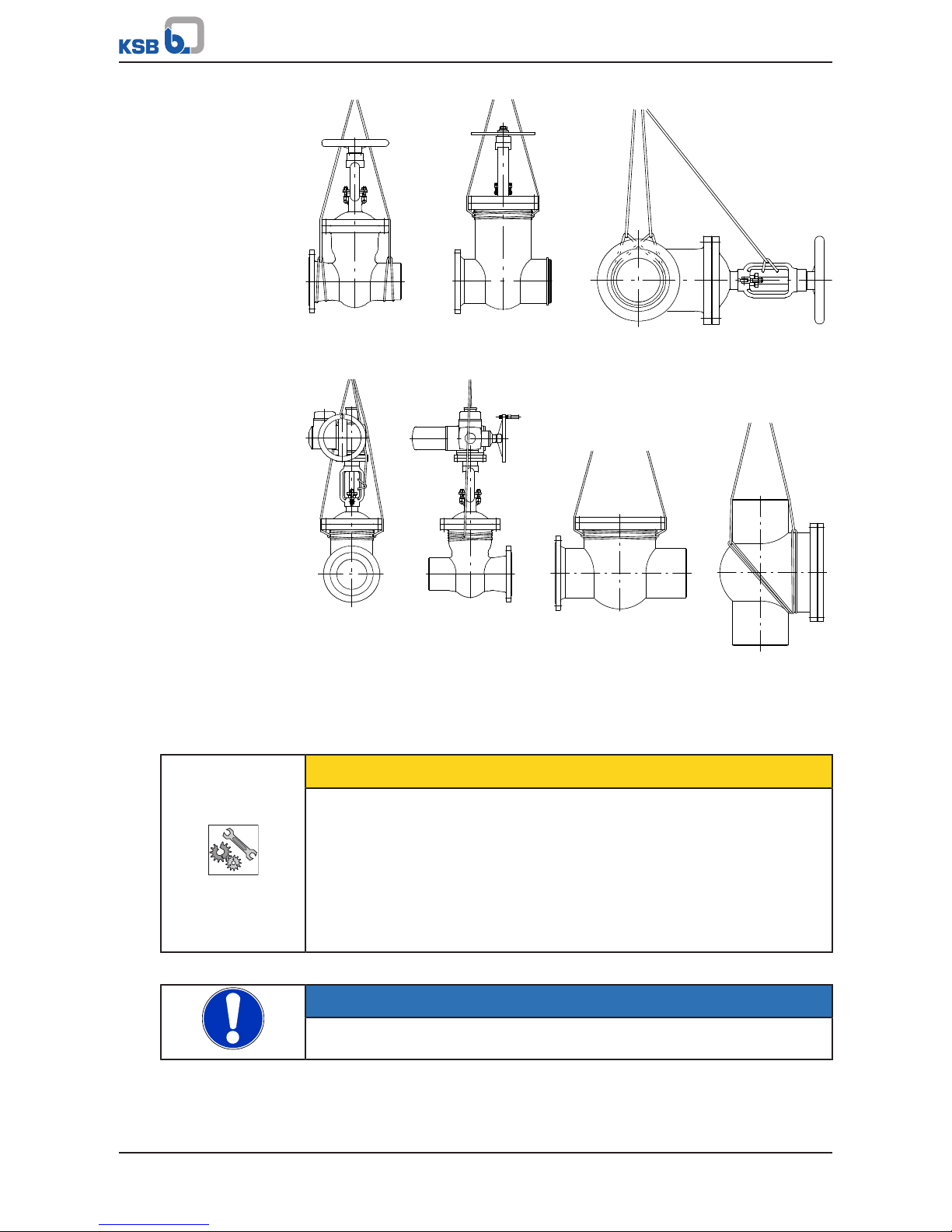
To transport the valve, suspend it from the lifting tackle as illustrated.
Page 12
3 Transport/Temporary Storage/Disposal
12 of 68
Fig.1: Transporting the valve
3.3 Storage/preservation
If commissioning is to take place some time after delivery, we recommend that the
following measures be taken for storing the valve:
CAUTION
Incorrect storage
Damage to the valve due to dirt, corrosion, moisture and/or frost!
▷ Store the valve in a dust- and vibration-free, frost-proof room where the
atmospheric humidity is as constant as possible (use suitable caps or film for
protection).
▷ Close the valve using little force and store in the closed position.
▷ Protect the valve from contact with solvents, lubricants, fuels or other
chemicals.
If properly stored indoors, the equipment is protected for a maximum of 12 months.
NOTE
For actuated valves, also observe the actuator's operating manual.
Page 13
3 Transport/Temporary Storage/Disposal
13 of 68
3.4 Return to supplier
1. Drain the valve as described in the manual.
2. Flush and clean the valve, particularly if it has been used for handling noxious,
explosive, hot or other hazardous fluids.
3. If the valve has handled fluids whose residues could lead to corrosion damage in
the presence of atmospheric humidity or could ignite upon contact with oxygen
also neutralise the valve and blow through with anhydrous inert gas to ensure
drying.
4. When returning valves used for handling Fluids in Group1 always complete and
enclose a certificate of decontamination.
Indicate any safety measures and decontamination measures taken.
NOTE
If required, a blank certificate of decontamination can be downloaded from the
following web site: www.ksb.com/certificate_of_decontamination
3.5 Disposal
WARNING
Fluids handled, consumables and supplies which are hot or pose a health hazard
Hazard to persons and the environment!
▷ Collect and properly dispose of flushing fluid and any residues of the fluid
handled.
▷ Wear safety clothing and a protective mask if required.
▷ Observe all legal regulations on the disposal of fluids posing a health hazard.
1. Dismantle the valve.
Collect greases and other lubricants during dismantling.
2. Separate and sort the valve materials, e.g. by:
- Metals
- Plastics
- Electronic waste
- Greases and other lubricants
3. Dispose of materials in accordance with local regulations or in another
controlled manner.
Page 14
4 Valve Description
14 of 68
4 Valve Description
4.1 General description
The sectional drawings below provide examples of the general design/configuration
of the valve. For additional and more detailed information, refer to the respective
type series booklet.
4.2 Marking
Table4: General marking
Nominal size DN ...
Nominal pressure class and/or max. permissible pressure/
temperature
PN ... / ... bar / ...
°C
Manufacturer KSB
Type series/model and/or order number NORI...
Year of construction 20..
Material .......
Flow direction arrow →
Traceability of the material .......
CE marking PED
Identification number of the notified body 0036
Customer's marking e.g. plant/
system No., etc.
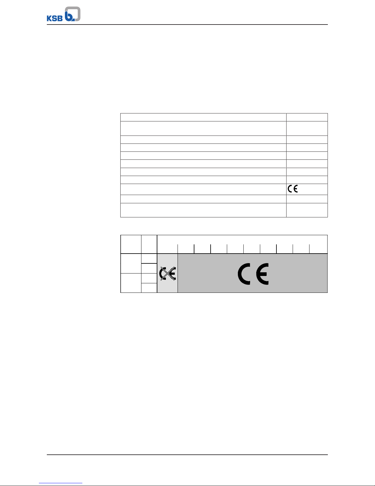
The CE marking on the valve indicates that it is in conformity with the European
Pressure Equipment Directive 2014/68/EU.
Fluids in Groups 1 and 2
Class PN DN
≤25 32 40 50 65 80 100 125 150 ≥200
10
16
25
≥
≥40
150
300
Fluid groups In accordance with Article13 Para.1 of Pressure Equipment Directive 2014/68/EU,
Group 1 comprises all fluids posing physical or health hazards, e.g. fluids defined as
▪ Explosive
▪ Extremely flammable
▪ Highly flammable
▪ Flammable: The maximum allowable temperature is above flashpoint
▪ Very toxic
▪ Toxic
▪ Oxidising
Group 2 comprises all other fluids not referred to in Group 1.
4.3 Gate Valves
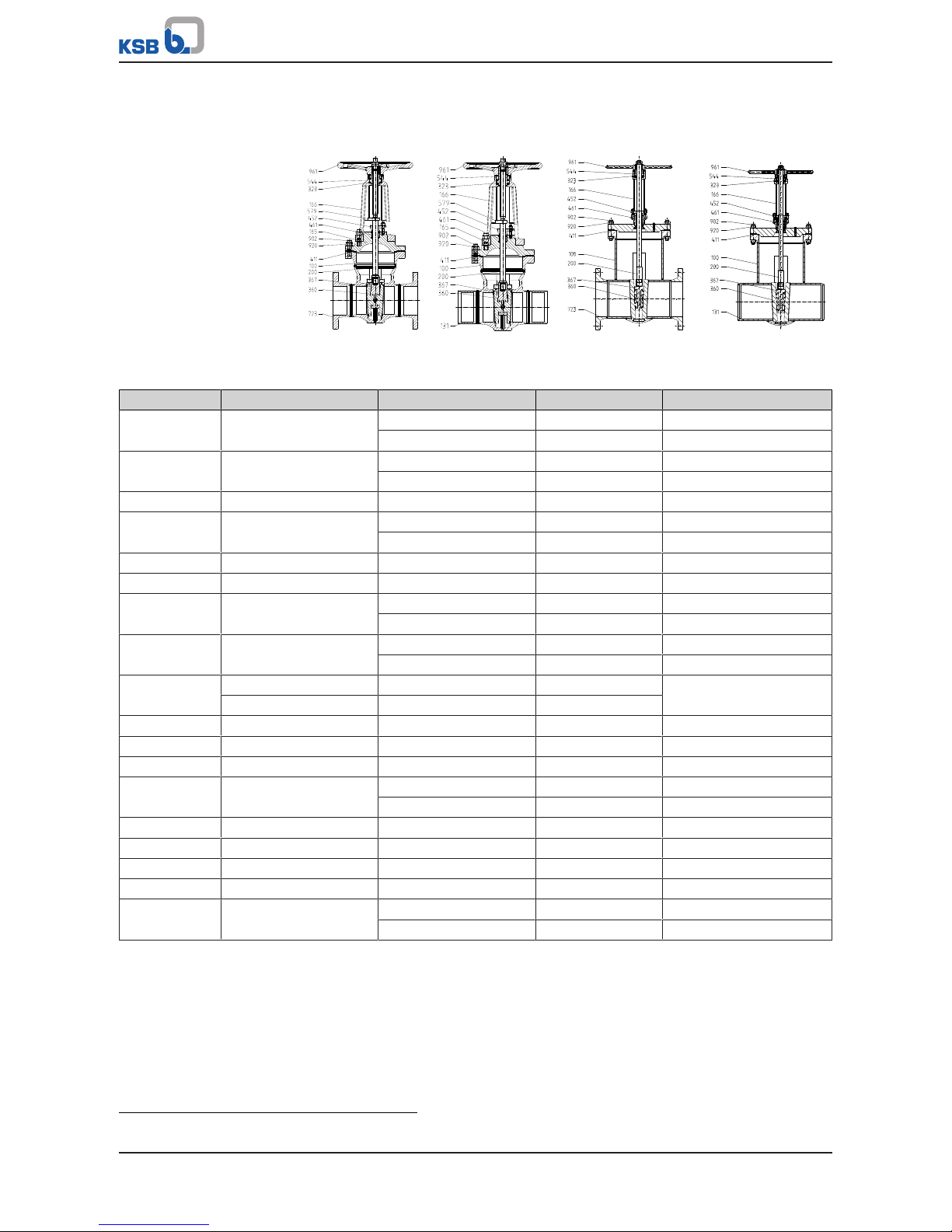
4.3.1 Function of gate valves with bolted bonnet
The valve consists of the pressure-retaining parts, i.e. body 100 and yoke 166, and the
functional unit.
Body 100 and yoke 166 are connected by studs 902.1 or grub screws 904 and nuts
920.1, and the joint is sealed off by joint ring 411.1.
Page 15
4 Valve Description
15 of 68
The functional unit consists mainly of wedge holder 367, flexibly mounted wedge
discs 360 and stem 200. The actuating element is either a handwheel 961 or an
actuator.
The seating faces of body 100 and wedge discs 360 are hard-faced. Gland packing
461, which seals off stem 200, is tightened via gland follower 452 by means of studs
902.3 or hinged bolts and nuts 920.2.
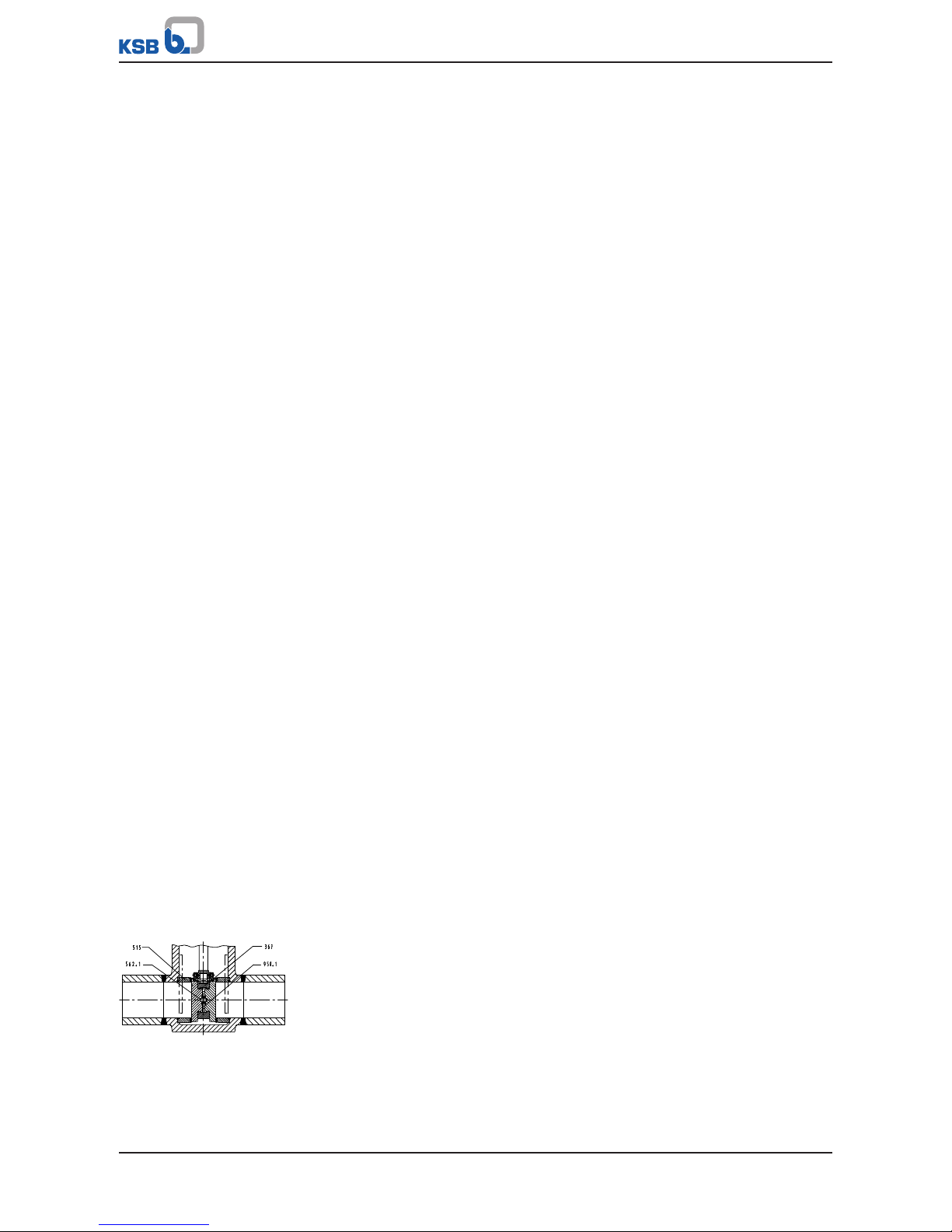
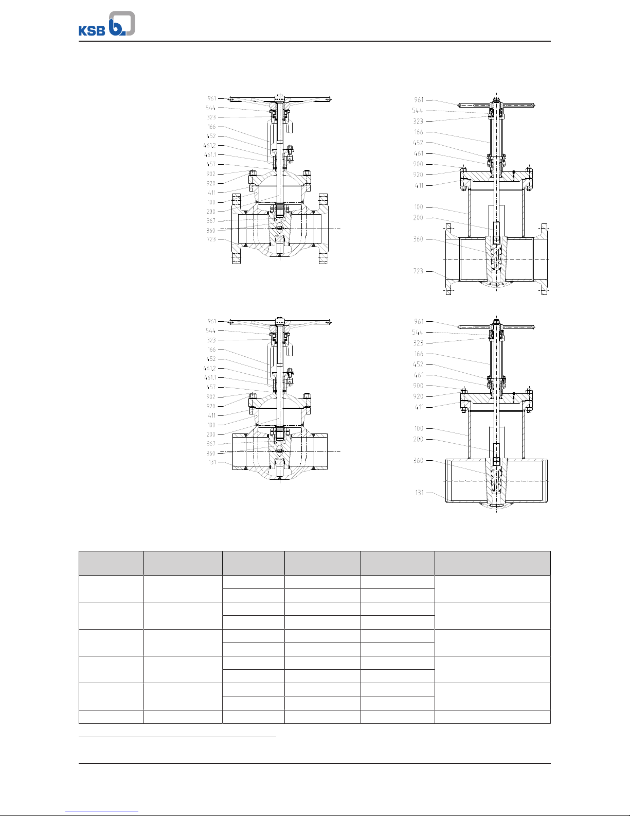
4.3.2 Function of gate valves with pressure seal bonnet
Gate valves with wedge discs 360 consist of body 100 with welded stellited seat rings
515, wedge discs 360 with stellited seating faces, bonnet 139 with gland packing 461
and yoke 166 with the actuating element.
Shut-off is performed by two wedge discs 360 pressed against seat rings 515; they are
flexibly mounted in wedge holder 367 and supported by replaceable thrust inserts
553 via pins 563.
Wedge holder 367 is screwed onto stem 200. A retainer prevents wedge discs 360
from twisting in wedge holder 367. To prevent twisting of the obturator
components, the wedge holder is guided in the body by lateral guide ribs 752. The
valve is equipped with a pressure seal bonnet.
The pressure inside body 100 presses bonnet 139 against joint ring 411.1, which is
supported by compression ring 501. The studs 902.2 and hexagon nuts 920.6, which
are supported by thrust plate 414 ensure that bonnet 139 is held in position against
joint ring 411.1, even if there is no pressure inside body 100.
For fitting a body pressure relief valve (ðSection4.4.1,Page29) (see type series
booklet 7300.1) a 22/14x74mm connection branch 131.2 is welded to body 100. The
connection branch is closed upon delivery.
Body pressure relief valves, if ordered, are supplied unassembled, i.e. attached loosely
to the gate valve.
Instead of fitting a body pressure relief valve, the operator may also provide a means
of pressure balancing between the body's middle section and the gate valve's
pressurised connection branch, e.g.:
▪ a pressure balancing hole in the seat ring or
▪ an external balancing line.
In this case the gate valve can be used for one flow direction only.
If gate valves and swing check valves in pressure seal design (bonnet 139) are fitted in
close proximity to one another, meaning that the trapped liquid could heat up if the
valves are closed, the operator must fit a body pressure relief valve.
Gland packing 461, which seals off stem 200, is tightened via gland follower 452 by
means of studs 902.3 and nuts 920.1. Stem 200 is moved in axial direction by the
rotating threaded bush 544, which is fitted with cylindrical roller bearings 323. Stem
200 lifts off wedge discs 360 or presses them against seat rings 515.
Threaded bush 544 is positioned in the yoke head by intermediate flange 729 and
hexagon socket head cap screws 914.1. Handwheel 961 sits on threaded bush 544, to
which it is joined via key 940. It is secured by circlip 932.
The stop nut 920.3 fitted on stem 200 serves as a travel stop in closing direction. It
prevents jamming of the wedge assembly in the seat and is secured by parallel pin
562.3.
Fig.2: Parallel discs
Unlike wedge gate valve designs, slide gate valves feature two parallel discs 368,
which are flexibly mounted in disc holder 367. The discs are supported by replaceable
disc springs 950.1 via parallel pins 562.1, which press them against seat rings 515.
Page 16
4 Valve Description
16 of 68
4.3.3 Gate Valves to DIN/EN with Bolted Bonnet
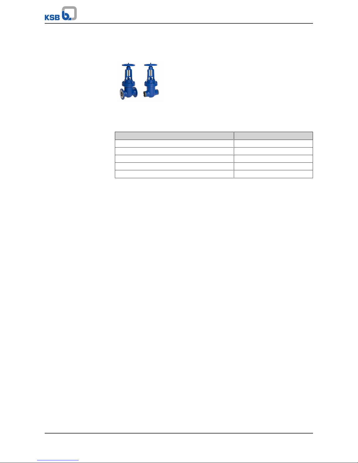
4.3.3.1 STAAL 40 AKD/AKDS
4.3.3.1.1 Operating data
Table5: Operating properties
Characteristic Value
Nominal pressure PN 10 - 40
Nominal size DN 50 - 600
Max. permissible pressure [bar] 40
Min. permissible temperature [°C] ≥-10
Max. permissible temperature [°C] ≤+450
Selection as per pressure/temperature ratings (ðSection4.3.3.1.4,Page17)
4.3.3.1.2 Fluids handled
▪ Water
▪ Steam
▪ Other non-aggressive fluids such as gas or oil on request.
4.3.3.1.3 Design details
Design
▪ Body of forged or welded steel construction
▪ Bolted bonnet
▪ Non-rotating stem with external screw
▪ Split wedge
▪ Standard position indicator ≤ DN200
▪ Yoke head suitable for mounting electric actuators (DINISO5210)
▪ The valves satisfy the safety requirements of AnnexI of the European Pressure
Equipment Directive2014/68/EU (PED) for fluids in Groups1and2.
▪ The valves do not have a potential internal source of ignition and can be used in
potentially explosive atmospheres, GroupII, category2 (zones1+21) and
category3 (zones2+22) to ATEX2014/34/EU.
Variants
▪ Stem protecting tube
▪ Stem protecting tube with position indicator (≥ DN250)
▪ Stem protecting tube with position switch (≥ DN250)
▪ Position switch(es) mounted on yoke (≤DN200)
▪ Bypass
▪ Drain branch
▪ Barrier water connection
▪ Electric actuators
Page 17

4 Valve Description
17 of 68
▪ Actuator installation kit
▪ Seat/disc interface made of wear-resistant and corrosion-proof Stellite
▪ Stem made of 1.4122
▪ TA-Luft-compliant model (with or without spring loading) for applications to
VDI2440 at temperatures ≤ 250°C and > 250°C (400°C maximum)
▪ Other flange designs or butt weld end designs
▪ Inspections to technical codes such as TRD/TRB/AD2000 – German Steam Boiler /
Pressure Vessel Regulations – or to customer specification
▪ ≥ DN 700 on request
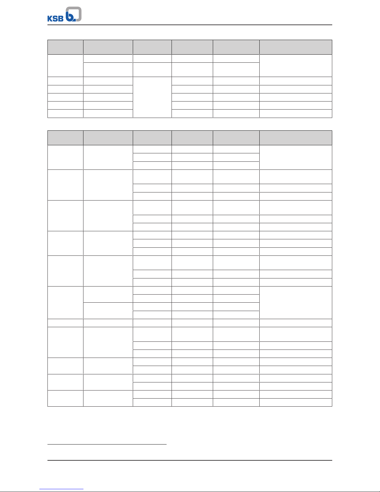
4.3.3.1.4 Pressure/temperature ratings
Table6: Permissible operating pressure [bar] (to EN 1092-1)
4)
PN Material [°C]
RT
5)
100 150 200 250 300 350 400 450
10 P250GH / P265GH 10,0 9,2 8,8 8,3 7,6 6,9 6,4 5,9 3,2
16 16,0 14,8 14,0 13,3 12,1 11,0 10,2 9,5 5,2
25 25,0 23,2 22,0 20,8 19,0 17,2 16,0 14,8 8,2
40 40,0 37,1 35,2 33,3 30,4 27,6 25,7 23,8 13,1
4) Operating pressures in accordance with DIN 2401 are also permissible.
5) RT: room temperature (-10°C to +50°C)
Page 18
4 Valve Description
18 of 68
4.3.3.1.5 Materials
PN 10 - 40
DN 50 - 200
PN 40
DN 250 - 600
AKD AKDS AKD AKDS
Table7: Parts list
Part No. Description Material Material number Note
100 Body P 250 GH 1.0460 -
P265GH 1.0425 ≥ DN 250
131.1 Connection branch P 235 GH 1.0345 P265GH 1.0425 ≥ DN 500
165 Bonnet P 250GH 1.0460 166 Yoke GP 240 GH+N 1.0619+N -
P265GH 1.0425 ≥ DN 250
200
6)
Stem X 20 Cr 13+QT800 1.4021+QT800 -
323
6)
Thrust bearing Steel - -
360
6)
Wedge discs GP 240 GH+N 1.0619+N -
P265GH 1.0425 ≥ DN 250
367
6)
Disc/wedge holder P 250 GH 1.0460 -
P265GH 1.0425 ≥ DN 250
Seat/disc
interface
Body X20CrMo171 1.4115 17% chrome steel
Wedge discs X8CrTi18 1.4502
411
6)
Joint ring CrNi steel/graphite - 452 Gland follower P250GH/P265GH 1.0460 / 1.0425 461
6)
Gland packing Pure graphite - 544
6)
Threaded bush 46S20+C 1.0727+C DN 50-200, nitrocarburised
11SMn30+C 1.0715+C ≥ DN 250, nitrided
579 Stop S235JR - 723 Flange P 250 GH 1.0460 902 Stud 25CrMo4 1.7218 920 Hexagon nut C35E 1.1181 961 Handwheel EN-GJL-250 5.1301 DN 50-200
Steel - ≥ DN 250
6) Recommended spare parts
Page 19
4 Valve Description
19 of 68
4.3.3.2 STAAL 100 AKD/AKDS
4.3.3.2.1 Operating data
Table8: Operating properties
Characteristic Value
Nominal pressure PN 63 - 100
Nominal size DN 50 - 500
Max. permissible pressure [bar] 100
Min. permissible temperature [°C] ≥-10
Max. permissible temperature [°C] ≤+530
Selection as per pressure/temperature ratings (ðSection4.3.3.2.4,Page20)
4.3.3.2.2 Fluids handled
▪ Water
▪ Steam
▪ Other non-aggressive fluids such as gas or oil on request.
4.3.3.2.3 Design details
Design
▪ Body of forged or welded steel construction
▪ Bolted bonnet
▪ Non-rotating stem with external screw
▪ Split wedge
▪ Yoke head suitable for mounting electric and pneumatic actuators (DINISO5210)
▪ The valves satisfy the safety requirements of Annex I of the European Pressure
Equipment Directive 2014/68/EU(PED) for fluids in Groups1and2.
▪ The valves do not have a potential internal source of ignition and can be used in
potentially explosive atmospheres, GroupII, category2 (zones1+21) and
category3 (zones2+22) to ATEX2014/34/EU.
Page 20
4 Valve Description
20 of 68
Variants
▪ Stem protecting tube
▪ Stem protecting tube with position indicator
▪ Limit switch(es)
▪ Bypass
▪ Drain branch
▪ Hard-faced back seat
▪ Threaded bush free from non-ferrous metals
▪ Electric actuators
▪ Pneumatic actuators
▪ Spur gear
▪ Bevel gear
▪ Actuating bush for remote actuation
▪ Other flange designs or butt weld end designs
▪ Inspections to technical codes such as TRD/TRB/AD2000 – German Steam Boiler /
Pressure Vessel Regulations – or to customer specification
▪ Die-forged model for DN300/250 on request.
▪ DN 500 and above on request
4.3.3.2.4 Pressure/temperature ratings
Table9: Permissible operating pressure [bar] (to EN 1092-1)
7)
PN Material [°C]
Designation Number RT8)100 150 200 250 300 350 400 450 460 470 480 490 500 510 520 530
63 P250GH 1.0460 63,0 58,5 55,5 52,5 48,0 43,5 40,5 37,5 20,7 - - - - - - - -
P265GH 1.0425 63,0 58,5 55,5 52,5 48,0 43,5 40,5 37,5 20,7 - - - - - - - 16Mo3 1.5415 63,0 63,0 63,0 63,0 61,5 54,0 51,0 47,1 43,5 40,3 37,2 34,1 31,0 27,9 - - 13CrMo4-5 1.7335 63,0 63,0 63,0 63,0 63,0 63,0 60,0 56,7 53,1 50,5 47,9 45,4 42,8 41,1 34,8 28,2 23,4
100 P250GH 1.0460 100,0 92,8 88,0 83,3 76,1 69,0 64,2 59,5 32,8 - - - - - - - -
P265GH 1.0425 100,0 92,8 88,0 83,3 76,1 69,0 64,2 59,5 32,8 - - - - - - - 16Mo3 1.5415 100,0 100,0 100,0 100,0 100,0 97,6 80,9 74,7 69,0 64,0 59,1 54,2 49,2 44,2 - - 13CrMo4-5 1.7335 100,0 100,0 100,0 100,0 100,0 100,0 95,2 90,0 84,2 80,2 76,1 72,0 68,0 65,2 55,2 44,7 37,1
7) Operating pressures in accordance with DIN 2401 are also permissible.
8) RT: room temperature (-10°C to +50°C)
Page 21
4 Valve Description
21 of 68
4.3.3.2.5 Materials
DN 50/50-250/250 DN 300/300-500/500
AKD AKD
AKDS AKDS
Table10: Parts list DN 50/50-250/250
Part No. Description Temperature
[°C]
Material Material number Note
100 Body ≤ 450 P 250 GH 1.0460 Body die-forged and
welded
≤ 530 13CrMo4-5 1.7335
723 Flange ≤ 450 P 250 GH 1.0460 -
≤ 530 13CrMo4-5 1.7335
131.1 Connection
branch
≤ 450 P 250 GH 1.0460 Material can be matched to
pipeline material
≤ 530 13CrMo4-5 1.7335
360
9)
Wedge discs ≤ 450 P 250 GH 1.0460 -
≤ 530 13CrMo4-5 1.7335
367
9)
Disc/wedge holder ≤ 450 P 250 GH 1.0460 -
≤ 530 13CrMo4-5 1.7335
166 Yoke ≤ 450 P 250 GH 1.0460 -
9) Recommended spare parts
Page 22

4 Valve Description
22 of 68
Part No. Description Temperature
[°C]
Material Material number Note
166 Yoke ≤ 530 13CrMo4-5 1.7335 Seat/disc
interface
Body ≤ 450 X20CrMo17-1 1.4115 Hard-faced
Wedge discs ≤ 530 Stellite
200
9)
Stem ≤ 530 X39CrMo17-1 1.4122 -
411
9)
Joint ring 1.4541/graphite - Serrated gasket
452 Gland follower P250GH 1.0460 457
9)
Neck ring G-X70CrMo292 1.4136 -
461.1/.2
9)
Gland packing Graphite - Compression-moulded
rings (confined)
544
9)
Threaded bush CuZn35Ni2 2.0540 On axial needle bearing
902.1 Stud 21CrMoV5-7 1.7709 -
920.1 Hexagon nut 25CrMo4 1.7218 961 Handwheel GG-25 0.6025 Non-rising
Table11: Parts list DN 300/300-500/500
Part No. Description Temperature
[°C]
Material Material number Note
100 Body ≤ 450 P265GH 1.0425 Body of welded steel
construction
≤ 500 16Mo3 1.5415
≤ 530 13CrMo4-5 1.7335
723 Flange ≤ 450 P 250 GH/P 265GH1.0460/1.0425 -
≤ 500 16Mo3 1.5415 ≤ 530 13CrMo4-5 1.7335 -
131.1 Connection
branch
≤ 450
≤ 500
≤ 530
P265GH
16Mo3
13CrMo4-5
1.0425
1.5415
1.7335
Material can be matched to
pipeline material
360
9)
Wedge discs 367
9)
Disc/wedge holder 166 Yoke Seat/disc
interface
Body ≤ 450 X20CrMo17-1 1.4115 Hard-faced
≤ 530 Stellite -
Wedge discs ≤ 450 X8CrTi18 1.4502
≤ 530 Stellite -
200
9)
Stem ≤ 530 X39CrMo17-1 1.4122 411
9)
Joint ring ≤ 530 1.4541/graphite - Serrated gasket
452 Gland follower P 250 GH/P 265GH1.0460/1.0425 -
461
9)
Gland packing Graphite - Compression-moulded
rings (confined)
544
9)
Threaded bush CuZn35Ni2 2.0540 On axial bearing
900 Screw ≤ 450 25CrMo4 1.7218 -
≤ 530 21CrMoV5-7 1.7709 -
920 Hexagon nut ≤ 450 25CrMo4 1.7218 -
≤ 530 25CrMo4 1.7218 -
961 Handwheel ≤ 530 Steel - Non-rising
Page 23
4 Valve Description
23 of 68
4.3.4 Gate Valves to DIN/EN in Pressure Seal Design
4.3.4.1 AKG-A/AKGS-A
4.3.4.1.1 Operating data
Table12: Operating properties
Characteristic Value
Nominal pressure PN 63 - 160
Nominal size DN 80/80-300/250
Max. permissible pressure [bar] 160
Min. permissible temperature [°C] ≥-10
Max. permissible temperature [°C] ≤+550
Selection as per pressure/temperature ratings (ðSection4.3.4.1.4,Page24)
4.3.4.1.2 Fluids handled
▪ Water
▪ Steam
▪ Other non-aggressive fluids such as gas or oil on request.
4.3.4.1.3 Design details
Design
▪ Pressure seal design
▪ Non-rotating stem
▪ Split wedge
▪ Yoke head suitable for mounting electric and pneumatic actuators (DINISO5210)
▪ The valves satisfy the safety requirements of Annex I of the European Pressure
Equipment Directive 2014/68/EU(PED) for fluids in Groups1and2.
▪ The valves do not have a potential internal source of ignition and can be used in
potentially explosive atmospheres, GroupII, category2 (zones1+21) and
category3 (zones2+22) to ATEX2014/34/EU.
Page 24

4 Valve Description
24 of 68
Variants
▪ Body made of forged steel
▪ Position indicator
▪ Limit switch(es)
▪ Drain branch
▪ Hard-faced back seat
▪ Disc spring supported yoke head
▪ Parallel discs
▪ Bypass
▪ Spur gear
▪ Bevel gear
▪ Electric actuators
▪ Pneumatic actuators
▪ Actuating bush for remote actuation
▪ Other flange designs
▪ Other butt weld end versions
▪ Inspections to technical codes such as TRD/TRB/AD2000 – German Steam Boiler /
Pressure Vessel Regulations – or to customer specification
4.3.4.1.4 Pressure/temperature ratings
Flanged ends, type AKG-A
Table13: Permissible operating pressures [bar]
10)
(to EN 1092-1)
11)
PN
Material [°C]
Designation Number RT
12)
100 150 200 250 300 350 400 450 460 470 480 490 500 510 520 530 540 550
63
P250GH 1.0460 63,0 58,5 55,5 52,5 48,0 43,5 40,5 37,5 20,7 - - - - - - - - - 13CrMo4-5 1.7335 63,0 63,0 63,0 63,0 63,0 63,0 60,0 56,7 53,1 50,5 47,9 45,4 42,8 41,1 34,8 28,2 23,4 18,3 14,7
100
P250GH 1.0460 100,0 92,8 88,0 83,3 76,1 69,0 64,2 59,5 32,8 - - - - - - - - - 13CrMo4-5 1.7335 100,0 100,0 100,0 100,0 100,0 100,0 95,2 90,0 84,2 80,2 76,1 72,0 68,0 65,2 55,2 44,7 37,1 29,0 23,3
160
P250GH 1.0460 160,0 148,5 140,9 133,3 121,9 110,4 102,8 95,2 52,5 - - - - - - - - - 13CrMo4-5 1.7335 160,0 160,0 160,0 160,0 160,0 160,0 152,3 144,0 134,8 128,3 121,8 115,3 108,8 104,3 88,3 71,6 59,4 46,4 37,3
Butt weld ends, unmachined, type AKGS-A
Table14: Permissible operating pressures [bar]
10)
PN
Material [°C]
Designation Number Up to
120
200 250 300 350 400 425 450 475 500 510 520 530 540 550
160
P250GH 1.0460 160 160 140 120 100 80 72 60 - - - - - - 13CrMo4-5 1.7335 160 160 160 160 160 150 147 145 140 118 100 80 67 52 42
10) The valves are suitable for temperatures down to -10 °C.
11) Operating pressures in accordance with DIN2401 are also permissible.
12) RT: room temperature (-10°C to +50°C)
Page 25

4 Valve Description
25 of 68
4.3.4.1.5 Materials
AKG-A AKGS-A
Table15: Parts list DN 50/50-250/200
Part No. Description Temperature
[°C]
Material Material number Note
100 Body ≤ 450 P 250 GH 1.0460 Body die-forged and welded
≤ 550 13CrMo4-5 1.7335
723 Flange ≤ 450 P 250 GH 1.0460 -
≤ 550 13CrMo4-5 1.7335 -
131.1 Connection branch ≤ 450 P 250 GH 1.0460 Material can be matched to
pipeline material
≤ 550 13CrMo4-5 1.7335
139 Bonnet ≤ 450 P 250 GH 1.0460 -
≤ 550 13CrMo4-5 1.7335
360
13)
Wedge discs ≤ 450 P 250 GH 1.0460 -
≤ 550 13CrMo4-5 1.7335
367
13)
Disc/wedge holder ≤ 450 P 250 GH 1.0460 -
≤ 550 13CrMo4-5 1.7335
162 Yoke bonnet ≤ 550 C22N 1.0402 Welded design
131.2 Connection branch 13CrMo4-5 1.7335 Seat/disc
interface
Body ≤ 450 Hard-faced 1.4115 Hard-faced
Wedge discs ≤ 550 Stellite hard-
faced
-
200
13)
Stem ≤ 550 X39CrMo17-1 1.4122 -
411.1
13)
Joint ring Pure graphite - 452 Gland follower 13CrMo4-5 1.7335 461
13)
Gland packing Pure graphite - With packing end rings
501 Segmental ring 13CrMo4-5 1.7335 544
13)
Threaded bush CuZn35Ni2 2.0540 On cylindrical roller bearings
961
13)
Handwheel EN-GJL-250 5.1301 ≥DN150 made of steel
(welded)
13) Recommended spare parts
Page 26
4 Valve Description
26 of 68
4.3.4.2 ZTS
4.3.4.2.1 Operating data
Table16: Operating properties
Characteristic Value
Design pressure [bar] ~ 600
Nominal size DN 50 - 800
Max. permissible pressure [bar] ~ 600
Min. permissible temperature [°C] ≥-10
Max. permissible temperature [°C] ≤+650
Selection as per pressure/temperature ratings (ðSection4.3.4.2.4,Page27)
4.3.4.2.2 Fluids handled
▪ Water
▪ Steam
▪ Other non-aggressive fluids such as gas or oil on request.
4.3.4.2.3 Design details
Design
▪ Body made of forged steel
▪ Pressure seal design
▪ Non-rotating stem
▪ Split wedge
▪ Yoke head suitable for mounting electric and pneumatic actuators (DINISO5210)
▪ Seat/disc interface made of wear-resistant and corrosion-proof Stellite
▪ The valves satisfy the safety requirements of Annex I of the European Pressure
Equipment Directive 2014/68/EU(PED) for fluids in Groups1and2.
▪ The valves do not have a potential internal source of ignition and can be used in
potentially explosive atmospheres, GroupII, category2 (zones1+21) and
category3 (zones2+22) to ATEX2014/34/EU.
Page 27

4 Valve Description
27 of 68
Variants
▪ Flanged ends
▪ Bypass
▪ Drain branch
▪ Parallel discs (type GTS)
▪ Pressure relief connections (3-branch system)
▪ Balancing hole in seat ring
▪ Hard-faced back seat
▪ Lantern ring in gland packing
▪ Disc spring supported threaded bush
▪ Packing combination for high-temperature applications
▪ Pressure seal joint ring capped with stainless steel
▪ Position indicator
▪ Limit switch(es)
▪ Spur gear
▪ Bevel gear
▪ Electric actuators
▪ Pneumatic actuators
▪ Actuating bush for remote actuation
▪ Threaded bush free from non-ferrous metals
▪ Locking device
▪ Inspections to technical codes such as TRD/TRB/AD2000 – German Steam Boiler /
Pressure Vessel Regulations – or to customer specification
4.3.4.2.4 Pressure/temperature ratings
Subseries B
14)
Table17: Permissible operating pressure [bar]
15)
Material Subseries
16)
[°C]
20 300 350 400 425 450 475 500 510 520 530 540 550 560 570 580 590 600
16Mo3
1.5415
B 100 86 81 75 72 69 57 44 - - - - - - - - - -
13CrMo4-5
1.7335
B 100 100 95 90 87 84 74 65 55 45 37 - - - - - - -
10CrMo9-10
1.7380/
11CrMo9-10
1.7383
B 100 100 98 93 90 88 76 64 56 49 43 37 32 - - - - -
X10CrMoVNb9-1
1.4903
B 100 100 100 100 100 100 100 100 100 100 96 87 79 71 64 57 50 45
Subseries C, D, E and F
Table18: Permissible operating pressure [bar]
15)17)
Material Subseries
16)
[°C]
20
100
150
200
250
300
350
400
425
450
475
500
510
520
530
540
550
560
570
580
590
600
610
620
630
640
650
P250GH
1.0460
C 212 202 181 161 141 126 105 85 76 66 - - - - - - - - - - - - - - - - D 323 308 277 246 215 192 161 130 115 100 - - - - - - - - - - - - - - - - E 426 407 366 325 284 254 213 172 152 132 - - - - - - - - - - - - - - - - -
14) DN 350-800
15) The valves are suitable for temperatures down to -10 °C.
16) The subseries determines the maximum operating pressure per temperature. The gate valve is designed and marked for the
actual design data specified in the purchase order.
17) The test pressure is defined in accordance with the provisions of the technical codes PED2014/68/EC; DINEN12516-2 and
EN12266-1.
Page 28

4 Valve Description
28 of 68
Material Subseries
16)
[°C]
20
100
150
200
250
300
350
400
425
450
475
500
510
520
530
540
550
560
570
580
590
600
610
620
630
640
650
P250GH
1.0460
F 521 496 446 397 347 310 260 210 186 160 - - - - - - - - - - - - - - - - -
15NiCuMoNb5
1.6368
C 367 367 367 367 367 356 341 327 314 242 - - - - - - - - - - - - - - - - CS
18)
445 445 445 445 445 430 415 400 380 300 - - - - - - - - - - - - - - - - -
D
19)
558 558 558 558 558 539 518 498 476 374 - - - - - - - - - - - - - - - - -
E 738 738 738 738 738 711 685 658 629 495 - - - - - - - - - - - - - - - - -
16Mo3
1.5415
C 268 237 214 192 177 151 147 141 140 136 134 94 66 52 42 - - - - - - - - - - - D 408 361 326 292 269 231 223 215 211 207 205 143 100 79 63 - - - - - - - - - - - E 539 478 432 386 356 304 294 284 279 275 269 189 132 104 83 - - - - - - - - - - - F 657 583 527 471 434 372 359 347 341 335 329 231 162 128 102 - - - - - - - - - - - -
13CrMo4-5
1.7335
C 268 243 228 213 202 187 177 167 162 157 155 138 118 95 79 61 49 - - - - - - - - - D 408 369 346 323 308 284 269 254 246 238 235 211 178 145 119 93 75 - - - - - - - - - E 539 488 457 427 407 376 355 335 325 315 310 277 236 191 158 124 100 - - - - - - - - - F 657 596 558 521 496 459 434 409 397 385 378 341 288 233 193 151 121 - - - - - - - - - -
10CrMo9-10
1.7380/
11CrMo9-10
1.7383
C 268 248 232 217 213 202 187 177 173 167 162 136 119 104 91 79 69 58 51 - - - - - - - D 408 377 354 331 323 308 284 269 262 254 246 207 181 158 138 119 104 89 78 - - - - - - - E 539 498 467 437 427 407 376 355 345 335 325 275 239 210 183 158 138 117 103 - - - - - - - F 657 608 570 533 521 496 459 434 422 409 397 335 292 255 223 193 168 144 126 - - - - - - - -
X10CrMoVNb9-1
1.4903
C - - - - - - - - - - - - - 245 225 204 185 166 148 131 116 102 89 78 67 59 50
D - - - - - - - - - - - - - 324 296 270 244 214 195 174 154 135 117 103 87 77 67
E - - - - - - - - - - - - - 470 429 391 353 316 283 251 221 197 170 148 126 112 96
F - - - - - - - - - - - - - 514 472 428 387 347 311 275 244 215 186 162 139 122 105
X10CrWMoVNb9-2
1.4901
C - - - - - - - - - - - - - - - - - - - 134 120 107 94 82 71 61 53
D - - - - - - - - - - - - - - - - - - - 201 180 160 142 123 106 92 79
E - - - - - - - - - - - - - - - - - - - 262 234 208 184 160 138 120 103
F - - - - - - - - - - - - - - - - - - - 314 281 250 221 192 166 144 124
4.3.4.2.5 Materials
DN 50/50 - 200/175 DN 200/200 - 500/450
with connection branch extensions without connection branch
extensions
18) Weights, dimensions and differential pressures on request.
19) Special CD subseries version on request. Depending on the nominal size, permissible operating pressures up to the
subseriesD pressure/temperature ratings are possible (subject to differential pressure limitations compared to subseriesD,
however).
20) Recommended spare parts
Page 29
4 Valve Description
29 of 68
Table19: Parts list
Part No. Description Materials for operating temperatures [°C] up to
450 530 550 570 600 650
101 Lower body section P250 GH
1.0460
15NiCuMoNb5
1.6368
16Mo3
1.5415
13CrMo4-5
1.7335
10CrMo9-10
1.7380/
11CrMo9-10
1.7383
X10CrMoVNb9-1
1.4903
X10CrWMoVNb 9-2
1.4901
102 Upper body section
108 Main body
131.1 Connection branch
139 Bonnet 10CrMo9-10
1.7380/
11CrMo9-10
1.7383
10CrMo9-10
1.7380/
11CrMo9-10
1.7383
501
20)
Segmental ring
360
20)
Wedge discs
hard-faced with
Stellite6
368
20)
Parallel discs
hard-faced with
Stellite6
515 Seat ring
hard-faced with
Stellite6
13CrMo4-5
1.7335
13CrMo4-5
1.7335
10CrMo9-10
1.7380/
11CrMo9-10
1.7383
131.2 Connection branch 13CrMo4-5
1.7335
11CrMo9-10
1.7383
X10CrMoVNb9-1
1.4903
166 Yoke 13CrMo4-5
1.7335
11CrMo9-10
1.7383
X10CrMoVNb9-1
1.4903
200
20)
Stem X39CrMo17-1
1.4122
X22CrMoV11-1
1.4923
X22CrMoV11-1
1.4923
X5NiCrTi2615
1.4980
367
20)
Disc/wedge holder 13CrMo4-5
1.7335
15NiCuMoNb5
1.6368
10CrMo9-10
1.7380/
11CrMo9-10
1.7383
X10CrMoVNb9-1
1.4903
411.1
20)
Joint ring Pure graphite, capped with stainless steel
452 Gland follower 13CrMo4-5
1.7335
10CrMo9-10
1.7380/
11CrMo9-10
1.7383
461
20)
Gland packing Pure graphite/stainless steel capped packing end rings
544
20)
Threaded bush Copper base alloys
961 Handwheel Steel
4.4 Body Pressure Relief Valve
4.4.1 UGS
4.4.1.1 Operating data
Table20: Operating properties
Characteristic Value
Nominal pressure ≥ PN 40
Nominal size DN 15
Max. permissible pressure 25 - 750bar
Page 30

4 Valve Description
30 of 68
4.4.1.2 Fluids handled
▪ Water
▪ Steam
▪ Other non-aggressive fluids such as gas or oil on request.
4.4.1.3 Design details
Design
▪ Body made of forged steel
▪ Stainless steel valve disc (UGS and UGSV)
▪ Adjustable, needle bearing supported spring assembly (UGS and UGSV)
▪ Blow-off pressure is set via screw-type body
▪ Stellited seat
▪ Lead-sealed screw prevents unauthorised manipulation of set blow-off pressure
▪ The valves satisfy the safety requirements of Annex I of the European Pressure
Equipment Directive 2014/68/EU(PED) for fluids in Groups1and2.
▪ The valves do not have a potential internal source of ignition and can be used in
potentially explosive atmospheres, GroupII, category2 (zones1+21) and
category3 (zones2+22) to ATEX2014/34/EU.
Variants
▪ Bursting disc (UGSV and UGSVA)
▪ Blocking device
▪ With lockable shut-off valve
Page 31

4 Valve Description
31 of 68
4.4.1.4 Materials
1)
1)
3)
2)
1)
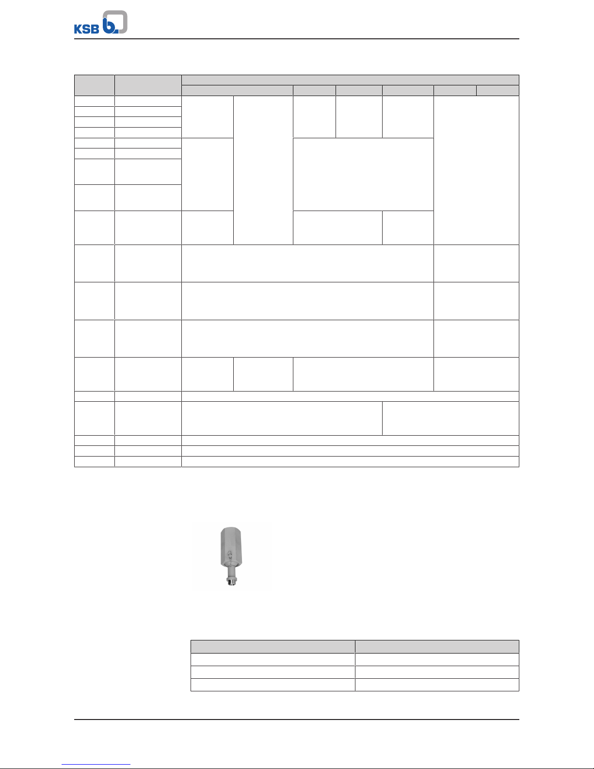
UGS:
without bursting disc, spring-loaded
UGSV:
with bursting disc, spring-loaded
UGSVA:
with bursting disc, without spring
loading
To be used in combination with
lockable globe valve only .
1) Lead-sealed 2) Paint dot
3) Name plate for bursting disc
Table21: Parts list
Part No. Description Material Material number Note
32-2 Axial needle bearing Steel - 160 Cover P250GH 1.0460 350 Valve disc X39CrMo17-1 1.4122 500 Ring X6CrNiTi18-10 1.4541 520 Sleeve 13CrMo4-5 1.7335 Stellited
550.1 Disc X20Cr13 1.4021 -
550.2 Bursting disc 316 SS - 574 Rod X39CrMo17-1 1.4122 731 Pipe union P250GH 1.0460 Stellited
13CrMo4-5 1.7335
10CrMo9-10/
11CrMo9-10
1.7380
1.7383
X10CrMoVNb9-1 1.4903
734 Screw-type body 9 SMn28 k - 900 Screw 5.8 - 901 Hexagon head bolt 8.8 - -
Page 32

4 Valve Description
32 of 68
Part No. Description Material Material number Note
920 Hexagon nut 8 - 950 Disc spring Inconel 718 - -
4.4.1.5 Heating up of trapped liquids
The heating up of trapped liquids primarily occurs inside gate valves.
If liquid remains in the body after pressure testing, for instance, or if condensate
develops due to certain operating conditions, there is a risk of an impermissible
pressure increase if the body is heated up by hot water or steam in one or both the
connected pipes. The potential pressure increase depends both on the temperature
and the extent to which the body is filled with liquid and may reach impermissible
values very quickly.
The problem of trapped liquids heating up inside the valve is particularly dangerous
on gate valves with a pressure seal bonnet as the bonnet seal becomes tighter with
rising pressure. The pressure may reach several times the operating pressure.
On gate valves with a bolted bonnet, an impermissible increase in pressure will be
relieved through leaks developing at the bonnet gasket.
Gate valves with a pressure seal bonnet, by contrast, must be fitted with body
pressure relief valves if excessive heating of trapped liquids is potentially a problem.
The body pressure relief valve ensures that the body is protected against excessive
loads and deformation under all operating conditions, thus avoiding incidents which
may compromise safety.
The likelihood of trapped liquid heating up varies depending on the system and must
be individually assessed for each gate valve by the purchaser. It is therefore necessary
to order the body pressure relief valve and the gate valve separately.
4.4.1.6 Function
Body pressure relief valves are available in three different designs:
▪ Spring-loaded body pressure relief valve (UGS)
▪ Spring-loaded body pressure relief valve with bursting disc (UGSV)
▪ Non-spring-loaded designs with bursting disc in combination with a lockable
globe valve (UGSVA).
Spring-loaded body
pressure relief valve (UGS)
Stainless steel valve disc 350 is pressed onto the stellited seat of pipe union 731 by
means of adjustable spring assembly 950 via disc 550.1 and rod 574, ensuring tight
closure.
The required pre-loading of disc springs 950 is adjusted via screw-type body 734,
supported by needle bearing 32-2. Screw-type body 734 is locked in position by
means of screw 900.
The blow-off pressure is always set at the supplying factory and stamped on the body
pressure relief valve. It is determined by the respective valve type, the operating data
and the max. permissible body load.
Every body pressure relief valve is tested and lead-sealed. Removal of the lead seal
will result in forfeiture of any warranty claims.
Setting and testing are performed on the basis of work instructions or parts list
specifications using special testing equipment. Re-setting can only be performed at
the supplying factory.
Spring-loaded body
pressure relief valve with
bursting disc (UGSV)
The body pressure relief valve with pre-fitted bursting disc basically consists of two
assemblies:
▪ Bursting disc with fastening elements
▪ Downstream spring-loaded body pressure relief valve
Bursting disc 550.2 is clamped between pipe union 731 and sleeve 520 and sealed by
means of intermediate ring 500.
It is combined with the downstream spring-loaded body pressure relief valve
described above.
Page 33

4 Valve Description
33 of 68
If bursting disc 550.2 bursts as a result of excessive pressure inside the gate valve, the
space between bursting disc 550.2 and the body pressure relief valve's seat is also
subjected to this excessive pressure. This causes valve disc 350 to lift off its seat and
the body pressure relief valve to blow off.
Excess pressure is relieved and the body is thus protected against excessive loads.
After blowing off, the body pressure relief valve closes again.
Despite the damaged bursting disc, operation of the gate valve with the body
pressure relief valve can be continued until the next maintenance inspection is due.
The bursting disc must then be renewed.
A paint dot at the point where the rod (574) passes through the screw-type body
(734) serves as a visual indicator. It indicates that the body pressure relief valve has
tripped and the bursting disc must have burst. When the body pressure relief valve
trips, this paint dot will burst open.
The paint dot must therefore be checked at regular intervals. The paint dot does not
affect the body pressure relief valve's functioning.
NOTE
Rupture of the bursting disc always indicates an impermissible pressure increase.
Before replacing the bursting disc, investigate the cause of this malfunction to rule
out any negative effects on the proper functioning of the valve.
Non-spring-loaded design
with bursting disc (UGSVA)
WARNING
Fluid escaping following rupture of bursting disc
Burns/scalding and damage/hazard to the environment!
▷ Take appropriate measures, e.g. fence off area.
Under normal operating conditions, the globe valve is locked in the open position. If
the globe valve is closed, the pressure relief function is not available.
The globe valve must be capable of reducing the amount of fluid escaping after the
bursting has ruptured, e.g. while the system is being shut down.
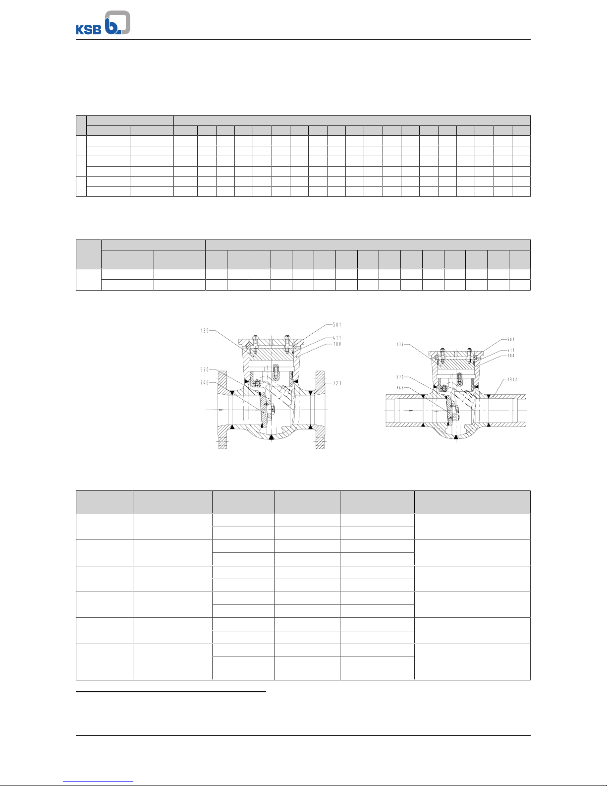
4.5 Swing check valves
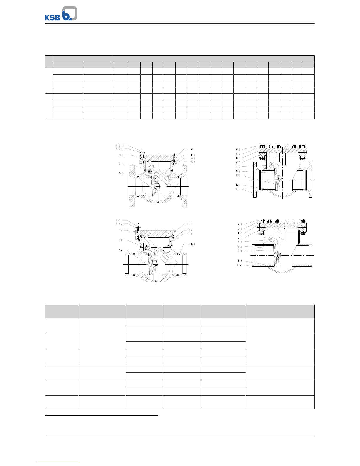
4.5.1 Function of swing check valves with bolted cover
Swing check valves consist of forged body 100 with hard-faced seating faces. Fluid
flow is shut off by hard-faced valve disc 746, which is flexibly mounted on hanger
arm 570. This connection is secured with a nut and a locking pin.
Body 100 is joined to cover 161 by studs 902.1 and sealed to atmosphere by joint ring
411.1. The disc assembly is pivot-mounted on hinge 230 welded to cover 161 or on
hinge pin 210 mounted in the body.
4.5.2 Function of swing check valves with pressure seal cover
The swing check valve is equipped with a pressure seal cover. The pressure inside
body 100 presses bonnet 139 against joint ring 411.1; the latter is supported by
segmental ring 501, which rests in a groove inside the body, via compression ring
500. Studs 902.2 and hexagon nuts 920.6, which are supported by cover 161, ensure
that bonnet 139 is held in place against joint ring 411.1, even if there is no pressure
inside body 100.
Hinge pin 210 held by bearing bushes 545 acts as a pivotal point for hanger arm 570
with valve disc 746. Together with plate 198, the hanger arm forms a complete
assembly that is inserted into body 100 and clamped and locked in place in a
circumferential groove inside the body by locking plates 196.
Page 34

4 Valve Description
34 of 68
4.5.3 Swing Check Valves with Bolted Cover
4.5.3.1 STAAL 40 AKK/AKKS
4.5.3.1.1 Operating data
Table22: Operating properties
Characteristic Value
Nominal pressure PN 10 - 40
Nominal size DN 80 - 400
Max. permissible pressure [bar] 40
Min. permissible temperature [°C] ≥-10
Max. permissible temperature [°C] ≤+450
Selection as per pressure/temperature ratings (ðSection4.5.3.1.4,Page35)
4.5.3.1.2 Fluids handled
▪ Water
▪ Steam
▪ Other non-aggressive fluids such as gas or oil on request.
4.5.3.1.3 Design details
Design
▪ Body of forged or welded steel construction
▪ Bolted cover
▪ Internally mounted hinge pin
▪ The valves satisfy the safety requirements of Annex I of the European Pressure
Equipment Directive 2014/68/EU(PED) for fluids in Groups1and2.
▪ The valves do not have a potential internal source of ignition and can be used in
potentially explosive atmospheres, GroupII, category2 (zones1+21) and
category3 (zones2+22) to ATEX2014/34/EU.
Variants
▪ Extended hinge pin from DN 250 (for lever and weight operation)
▪ Other flange designs
▪ Other butt weld end versions
▪ Drain branch
▪ Seat/disc interface made of wear-resistant and corrosion-proof Stellite
▪ Inspections to technical codes such as TRD/TRB/AD2000 – German Steam Boiler /
Pressure Vessel Regulations – or to customer specification
▪ DN 500 and above on request
21) Operating pressures in accordance with DIN2401 are also permissible.
Page 35

4 Valve Description
35 of 68
4.5.3.1.4 Pressure/temperature ratings
Table23: Permissible operating pressure [bar] (to EN 1092-1)
21)
PN Material [°C]
RT
22)
100 150 200 250 300 350 400 450
10 P235GH / P265GH 10,0 9,2 8,8 8,3 7,6 6,9 6,4 5,9 3,2
16 16,0 14,8 14,0 13,3 12,1 11,0 10,2 9,5 5,2
25 25,0 23,2 22,0 20,8 19,0 17,2 16,0 14,8 8,2
40 40,0 37,1 35,2 33,3 30,4 27,6 25,7 23,8 13,1
4.5.3.1.5 Materials
AKK AKKS
Table24: Parts list
Part No. Description Material Material number Note
100 Body P 235 GH 1.0345 -
P265GH 1.0425 -
131.1 Connection branch P 235 GH 1.0305 161 Body cover P265GH 1.0425 210
23)
Hinge pin X 20 Cr 13 1.4021 -
Seat/disc
interface
Body X20CrMo171 1.4115 17% chrome steel
Valve disc X8CrTi18 1.4502
411
23)
Joint ring Pure graphite - -
570
23)
Hanger arm P265GH 1.0425 723 Flange P 250 GH 1.0460 746
23)
Valve disc P265GH 1.0425 900 Screw 25CrMo4 1.7218 920 Hexagon nut C35E 1.1181 -
22) RT: room temperature (-10 °C to +50 °C)
23) Recommended spare parts
Page 36

4 Valve Description
36 of 68
4.5.3.2 STAAL 100 AKK/AKKS
4.5.3.2.1 Operating data
Table25: Operating properties
Characteristic Value
Nominal pressure PN 63 - 100
Nominal size DN 80 - 400
Max. permissible pressure [bar] 100
Min. permissible temperature [°C] ≥-10
Max. permissible temperature [°C] ≤+530
Selection as per pressure/temperature ratings (ðSection4.5.3.2.4,Page37)
4.5.3.2.2 Fluids handled
▪ Water
▪ Steam
▪ Other non-aggressive fluids such as gas or oil on request.
4.5.3.2.3 Design details
Design
▪ Body of forged or welded steel construction
▪ Bolted cover
▪ Internally mounted hinge pin
▪ The valves satisfy the safety requirements of Annex I of the European Pressure
Equipment Directive 2014/68/EU(PED) for fluids in Groups1and2.
▪ The valves do not have a potential internal source of ignition and can be used in
potentially explosive atmospheres, GroupII, category2 (zones1+21) and
category3 (zones2+22) to ATEX2014/34/EU.
Variants
▪ Extended hinge pin from DN 250 (for lever and weight operation)
▪ Other flange designs
▪ Other butt weld end versions
▪ Drain branch
▪ Inspections to technical codes such as TRD/TRB/AD2000 – German Steam Boiler /
Pressure Vessel Regulations – or to customer specification
▪ DN 50 and DN 65 on request
▪ DN 400 and above on request.
25) RT: room temperature (-10°C to +50°C)
Page 37
4 Valve Description
37 of 68
4.5.3.2.4 Pressure/temperature ratings
Table26: Permissible operating pressure [bar] (to EN1092-1)
25)
PN
Material [°C]
Designation Number RT
25)
100 150 200 250 300 350 400 450 460 470 480 490 500 510 520 530
63
P250GH 1.0460 63,0 58,5 55,5 52,5 48,0 43,5 40,5 37,5 20,7 - - - - - - - P265GH 1.0425 63,0 58,5 55,5 52,5 48,0 43,5 40,5 37,5 20,7 - - - - - - - 16Mo3 1.5415 63,0 63,0 63,0 63,0 61,5 54,0 51,0 47,1 43,5 40,3 37,2 34,1 31,0 27,9 - - 13CrMo4-5 1.7335 63,0 63,0 63,0 63,0 63,0 63,0 60,0 56,7 53,1 50,5 47,9 45,4 42,8 41,1 34,8 28,2 23,4
100
P250GH 1.0460 100,0 92,8 88,0 83,3 76,1 69,0 64,2 59,5 32,8 - - - - - - - P265GH 1.0425 100,0 92,8 88,0 83,3 76,1 69,0 64,2 59,5 32,8 - - - - - - - 16Mo3 1.5415 100,0 100,0 100,0 100,0 100,0 97,6 80,9 74,7 69,0 64,0 59,1 54,2 49,2 44,2 - - 13CrMo4-5 1.7335 100,0 100,0 100,0 100,0 100,0 100,0 95,2 90,0 84,2 80,2 76,1 72,0 68,0 65,2 55,2 44,7 37,1
4.5.3.2.5 Materials
DN 80/80-250/250 DN 300/300-400/400
AKK AKK
AKKS AKKS
Table27: Parts list DN 80/80-250/250
Part No. Description Temperature
[°C]
Material Material number Note
100 Body ≤ 450 P 250 GH 1.0460 Body die-forged and welded
≤ 530 13CrMo4-5 1.7335
723 Flange ≤ 450 P 250 GH 1.0460 -
≤ 530 13CrMo4-5 1.7335
131.1 Connection branch ≤ 450 P 250 GH 1.0460 Material can be matched to
pipeline material.
≤ 530 13CrMo4-5 1.7335
161 Body cover ≤ 450 P 250 GH 1.0460 -
≤ 530 13CrMo4-5 1.7335
746
26)
Valve disc ≤ 450 P 250 GH 1.0460 -
≤ 530 13CrMo4-5 1.7335
Seat/disc
interface
Body ≤ 450 X20CrMo17-1 1.4115 Hard-faced
24) Operating pressures in accordance with DIN2401 are also permissible.
26) Recommended spare parts
Page 38
4 Valve Description
38 of 68
Part No. Description Temperature
[°C]
Material Material number Note
Seat/disc
interface
Body ≤ 530 Stellite - Hard-faced
Valve disc ≤ 530 X15CrNiMn18-81.4370
411
26)
Joint ring ≤ 530 1.4541/graphite - Serrated gasket
570
26)
Hanger arm 13CrMo4-5 1.7335 -
210 Hinge pin X39CrMo17-1 1.4122 -
902.1 Stud 21CrMoV5-7 1.7709 -
920.1 Hexagon nut 25CrMo4 1.7218 -
Table28: Parts list DN 300/300-400/400
Part No. Description Temperature
[°C]
Material Material number Note
100 Body ≤ 450 P265GH 1.0425 Body of welded steel
construction
≤ 500 16Mo3 1.5415
≤ 530 13CrMo4-5 1.7335
723 Flange ≤ 450 P 250 GH/P 265GH1.0460/1.0425 -
≤ 500 16Mo3 1.5415 ≤ 530 13CrMo4-5 1.7335 -
131.1 Connection branch ≤ 450 P265GH 1.0425 Material can be matched to
pipeline material.
≤ 500 16Mo3 1.5415 ≤ 530 13CrMo4-5 1.7335 -
161 Body cover ≤ 450 P265GH 1.0425 -
≤ 500 16Mo3 1.5415 ≤ 530 13CrMo4-5 1.7335 -
746
27)
Valve disc ≤ 450 P 250 GH/P 265GH1.0460/1.0425 -
≤ 500 16Mo3 1.5415 ≤ 530 13CrMo4-5 1.7335 -
Seat/disc
interface
Body ≤ 450 X20CrMo17-1 1.4115 Hard-faced
≤ 530 Stellite -
Valve disc ≤ 450 X8CrTi18 1.4502
≤ 530 Stellite -
411
27)
Joint ring ≤ 530 1.4541/graphite - Serrated gasket
570
27)
Hanger arm ≤ 450 P 250 GH/P 265GH1.0460/1.0425 -
≤ 530 16Mo3 1.5415 ≤ 530 13CrMo4-5 1.7335 -
210
27)
Hinge pin ≤ 450 X20Cr13 1.4021 -
≤ 530 X39CrMo17-1 1.4122 -
900 Screw ≤ 450 25CrMo4 1.7218 -
≤ 530 21CrMoV5-7 1.7709 -
920 Hexagon nut ≤ 450 25CrMo4 1.7218 -
≤ 530 25CrMo4 1.7218 -
27) Recommended spare parts
Page 39

4 Valve Description
39 of 68
4.5.4 Swing check valves with pressure seal cover
4.5.4.1 AKR/AKRS
4.5.4.1.1 Operating data
Table29: Operating properties
Characteristic Value
Nominal pressure PN 63 - 160
Nominal size DN 80/80-300/250
Max. permissible pressure [bar] 160
Min. permissible temperature [°C] ≥-10
Max. permissible temperature [°C] ≤+550
Selection as per pressure/temperature ratings (ðSection4.5.4.1.4,Page40)
4.5.4.1.2 Fluids handled
▪ Water
▪ Steam
▪ Other non-aggressive fluids such as gas or oil on request.
4.5.4.1.3 Design details
Design
▪ Body of forged or welded steel construction
▪ Pressure seal design
▪ Internally mounted hinge pin
▪ The valves satisfy the safety requirements of Annex I of the European Pressure
Equipment Directive 2014/68/EU(PED) for fluids in Groups1and2.
▪ The valves do not have a potential internal source of ignition and can be used in
potentially explosive atmospheres, GroupII, category2 (zones1+21) and
category3 (zones2+22) to ATEX2014/34/EU.
Variants
▪ Other flange designs
▪ Other butt weld end versions
▪ Inspections to technical codes such as TRD/TRB/AD2000 – German Steam Boiler /
Pressure Vessel Regulations – or to customer specification
30) RT: room temperature (-10°C to +50°C)
Page 40
4 Valve Description
40 of 68
4.5.4.1.4 Pressure/temperature ratings
Flanged ends, type AKR (to EN1092-1)
29)
Table30: Permissible operating pressures [bar]
30)
PN
Material [°C]
Designation Number RT
30)
100 150 200 250 300 350 400 450 460 470 480 490 500 510 520 530 540 550
63
P250GH 1.0460 63,0 58,5 55,5 52,5 48,0 43,5 40,5 37,5 20,7 - - - - - - - - - 13CrMo4-5 1.7335 63,0 63,0 63,0 63,0 63,0 63,0 60,0 56,7 53,1 50,5 47,9 45,4 42,8 41,1 34,8 28,2 23,4 18,3 14,7
100
P250GH 1.0460 100,0 92,8 88,0 83,3 76,1 69,0 64,2 59,5 32,8 - - - - - - - - - 13CrMo4-5 1.7335 100,0 100,0 100,0 100,0 100,0 100,0 95,2 90,0 84,2 80,2 76,1 72,0 68,0 65,2 55,2 44,7 37,1 29,0 23,3
160
P250GH 1.0460 160,0 148,5 140,9 133,3 121,9 110,4 102,8 95,2 52,5 - - - - - - - - - 13CrMo4-5 1.7335 160,0 160,0 160,0 160,0 160,0 160,0 152,3 144,0 134,8 128,3 121,8 115,3 108,8 104,3 88,3 71,6 59,4 46,4 37,3
Butt weld ends, machined, type AKRS
28)
Table31: Permissible operating pressures [bar]
29)
PN Material [°C]
Designation Number Up to
120
200 250 300 350 400 425 450 475 500 510 520 530 540 550
63/160 P250GH 1.0460 160 160 140 120 100 80 72 60 - - - - - - -
13CrMo4-5 1.7335 160 160 160 160 160 150 147 145 140 118 100 80 67 52 42
4.5.4.1.5 Materials
AKR AKRS
Table32: Parts list
Part No. Description Temperature
[°C]
Material Material number Note
100 Body ≤ 450°C P 250GH 1.0460 Body die-forged and welded
≤ 550°C 13CrMo4-5 1.7335
723 Flange ≤ 450°C P 250GH 1.0460 -
≤ 550°C 13CrMo4-5 1.7335
131.1 Connection branch ≤ 450°C P 250GH 1.0460 Material can be matched to
pipeline material.
≤ 550°C 13CrMo4-5 1.7335
746
31)
Valve disc ≤ 450°C P 250GH 1.0460 -
≤ 550°C 13CrMo4-5 1.7335
139 Bonnet ≤ 450°C P 250GH 1.0460 -
≤ 550°C 13CrMo4-5 1.7335
Seat/disc
interface
Body ≤ 450°C Hard-faced 1.4115 Hard-faced
≤ 550°C Stellite hard-
faced
-
28) Operating pressures in accordance with DIN2401 are also permissible.
29) The valves are suitable for temperatures down to -10 °C.
31) Recommended spare parts
Page 41

4 Valve Description
41 of 68
Part No. Description Temperature
[°C]
Material Material number Note
Seat/disc
interface
Valve disc ≤ 550°C Stainless steel
hard-faced
1.4370 Hard-faced
411
31)
Joint ring ≤ 550°C Pure graphite - 501 Segmental ring 13CrMo4-5 1.7335 570 Hanger arm 13CrMo4-5 1.7335 -
4.5.4.2 ZRS
4.5.4.2.1 Operating data
Table33: Operating properties
Characteristic Value
Design pressure [bar] ~ 600
Nominal size DN 50/50-500/450
Max. permissible pressure [bar] ~ 600
Min. permissible temperature [°C] ≥-10
Max. permissible temperature [°C] ≤+650
Larger nominal sizes on request.
Selection as per pressure/temperature ratings (ðSection4.5.4.2.4,Page43)
4.5.4.2.2 Fluids handled
▪ Water
▪ Steam
▪ Other non-aggressive fluids such as gas or oil on request.
4.5.4.2.3 Design details
Design
▪ Body made of forged steel
▪ Pressure seal design
▪ Internally mounted hinge pin
▪ Seat/disc interface made of wear-resistant and corrosion-proof Stellite
▪ The valves satisfy the safety requirements of Annex I of the European Pressure
Equipment Directive 2014/68/EU(PED) for fluids in Groups1and2.
▪ The valves do not have a potential internal source of ignition and can be used in
potentially explosive atmospheres, GroupII, category2 (zones1+21) and
category3 (zones2+22) to ATEX2014/34/EU.
Page 42

4 Valve Description
42 of 68
Variants
▪ Flanged ends
▪ Minimum flow connections
▪ Other butt weld end versions
▪ Inspections to technical codes such as TRD/TRB/AD2000 – German Steam Boiler /
Pressure Vessel Regulations – or to customer specification
Page 43

4 Valve Description
43 of 68
4.5.4.2.4 Pressure/temperature ratings
Table34: Permissible operating pressure [bar]
32)33)
Material Subseries
34)
[°C]
20
100
150
200
250
300
350
400
425
450
475
500
510
520
530
540
550
560
570
580
590
600
610
620
630
640
650
P250GH
1.0460
C 212 202 181 161 141 126 105 85 76 66 - - - - - - - - - - - - - - - - D 323 308 277 246 215 192 161 130 115 100 - - - - - - - - - - - - - - - - E 426 407 366 325 284 254 213 172 152 132 - - - - - - - - - - - - - - - - F 521 496 446 397 347 310 260 210 186 160 - - - - - - - - - - - - - - - - -
15NiCuMoNb5
1.6368
C 367 367 367 367 367 356 341 327 314 242 - - - - - - - - - - - - - - - - CS
35)
445 445 445 445 445 430 415 400 380 300 - - - - - - - - - - - - - - - - -
D
36)
558 558 558 558 558 539 518 498 476 374 - - - - - - - - - - - - - - - - -
E 738 738 738 738 738 711 685 658 629 495 - - - - - - - - - - - - - - - - -
16Mo3
1.5415
C 268 237 214 192 177 151 147 141 140 136 134 94 66 52 42 - - - - - - - - - - - D 408 361 326 292 269 231 223 215 211 207 205 143 100 79 63 - - - - - - - - - - - E 539 478 432 386 356 304 294 284 279 275 269 189 132 104 83 - - - - - - - - - - - F 657 583 527 471 434 372 359 347 341 335 329 231 162 128 102 - - - - - - - - - - - -
13CrMo4-5
1.7335
C 268 243 228 213 202 187 177 167 162 157 155 138 118 95 79 61 49 - - - - - - - - - D 408 369 346 323 308 284 269 254 246 238 235 211 178 145 119 93 75 - - - - - - - - - E 539 488 457 427 407 376 355 335 325 315 310 277 236 191 158 124 100 - - - - - - - - - F 657 596 558 521 496 459 434 409 397 385 378 341 288 233 193 151 121 - - - - - - - - - -
10CrMo9-10
1.7380/
11CrMo9-10
1.7383
C 268 248 232 217 213 202 187 177 173 167 162 136 119 104 91 79 69 58 51 - - - - - - - D 408 377 354 331 323 308 284 269 262 254 246 207 181 158 138 119 104 89 78 - - - - - - - E 539 498 467 437 427 407 376 355 345 335 325 275 239 210 183 158 138 117 103 - - - - - - - F 657 608 570 533 521 496 459 434 422 409 397 335 292 255 223 193 168 144 126 - - - - - - - -
X10CrMoVNb9-1
1.4903
C - - - - - - - - - - - - - 245 225 204 185 166 148 131 116 102 89 78 67 59 50
D - - - - - - - - - - - - - 324 296 270 244 214 195 174 154 135 117 103 87 77 67
E - - - - - - - - - - - - - 470 429 391 353 316 283 251 221 197 170 148 126 112 96
F - - - - - - - - - - - - - 514 472 428 387 347 311 275 244 215 186 162 139 122 105
X10CrWMoVNb9-2
1.4901
C - - - - - - - - - - - - - - - - - - - 134 120 107 94 82 71 61 53
D - - - - - - - - - - - - - - - - - - - 201 180 160 142 123 106 92 79
E - - - - - - - - - - - - - - - - - - - 262 234 208 184 160 138 120 103
F - - - - - - - - - - - - - - - - - - - 314 281 250 221 192 166 144 124
32) The valves are suitable for temperatures down to -10 °C.
33) The test pressure is defined in accordance with the provisions of the technical codes PED2014/68/EC; DINEN12516-2 and
EN12266-1.
34) The subseries defines the maximum operating pressure possible for the respective temperature. The swing check valve is
selected and marked according to the actual design data specified in the order.
35) Weights, dimensions and differential pressures on request.
36) Special design subseries CD on request. Depending on the nominal size, permissible operating pressures up to the
maximum pressure and temperature of subseries D are possible (however, with restrictions regarding the differential
pressure for subseries D).
Page 44

4 Valve Description
44 of 68
4.5.4.2.5 Materials
DN 50/50 - 200/175 DN 200/200 - 500/450
with connection branch extensions without connection branch
extensions
Table35: Parts list
Part No. Description Materials for operating temperatures [°C] up to
450 530 550 570 600 650
101 Lower body section P 250 GH
1.0460
15NiCuMoNb5
1.6368
16 Mo 3
1.5415
13 CrMo 4-5
1.7335
10CrMo9-10
1.7380/
11CrMo9-10
1.7383
X10CrMoVNb 9-1
1.4903
X10CrWMoVNb 9-2
1.4901
102 Upper body section
108 Main body
131.1 Connection branch
139 Bonnet 10CrMo9-10
1.7380/
11CrMo9-10
1.7383
10CrMo9-10
1.7380/
11CrMo9-10
1.7383
501
37)
Segmental ring
746
37)
Valve disc
hard-faced
1.7380 NP 1.6368 H21 1.7380 NP 1.4903 H21
515 Seat ring
hard-faced
13 CrMo 4-5
1.7335 H21
1.6368 H6 13 CrMo 4-5
1.7335 H21
10CrMo9-10
1.7380 H6/
11CrMo9-10
1.7383 H6
1.4903 H6
196 Locking plate 13 CrMo 4-5
1.7335
10CrMo9-10
1.7380/
11CrMo9-10
1.7383
X10CrMoVNb 9-1
1.4903
198 Plate 13 CrMo 4-5
1.7335
10CrMo9-10
1.7380/
11CrMo9-10
1.7383
X10CrMoVNb 9-1
1.4903
210
37)
Hinge pin X39CrMo17-1
1.4122
X20CrMoV11-1
1.4922
411.1
37)
Joint ring Pure graphite
570
37)
Hanger arm 13 CrMo 4-5
1.7335
10CrMo9-10
1.7380/
11CrMo9-10
1.7383
X10CrMoVNb 9-1
1.4903
37) Recommended spare parts
Page 45

4 Valve Description
45 of 68
4.6 Line Blind Valve
4.6.1 VTS
4.6.1.1 Operating data
Table36: Operating properties
Characteristic Value
Design pressure [bar] ~ 600
Nominal size DN 200 - 500
Max. permissible pressure [bar] ~ 600
Min. permissible temperature [°C] ≥-10
Max. permissible temperature [°C] ≤+650
Selection as per pressure/temperature ratings (ðSection4.6.1.4,Page46)
4.6.1.2 Fluids handled
▪ Water
▪ Steam
▪ Other non-aggressive fluids such as gas or oil on request.
4.6.1.3 Design details
Design
▪ Body made of forged steel
▪ Pressure seal design
▪ Position indicator
▪ The valves satisfy the safety requirements of Annex I of the European Pressure
Equipment Directive 2014/68/EU(PED) for fluids in Groups1and2.
▪ The valves do not have a potential internal source of ignition and can be used in
potentially explosive atmospheres, GroupII, category2 (zones1+21) and
category3 (zones2+22) to ATEX2014/34/EU.
Variants
▪ Limit switch(es)
▪ Flanged ends
▪ Extended nozzles
▪ Blow-out attachment
▪ Inspections to technical codes such as TRD/TRB/AD2000 – German Steam Boiler /
Pressure Vessel Regulations – or to customer specification
Page 46
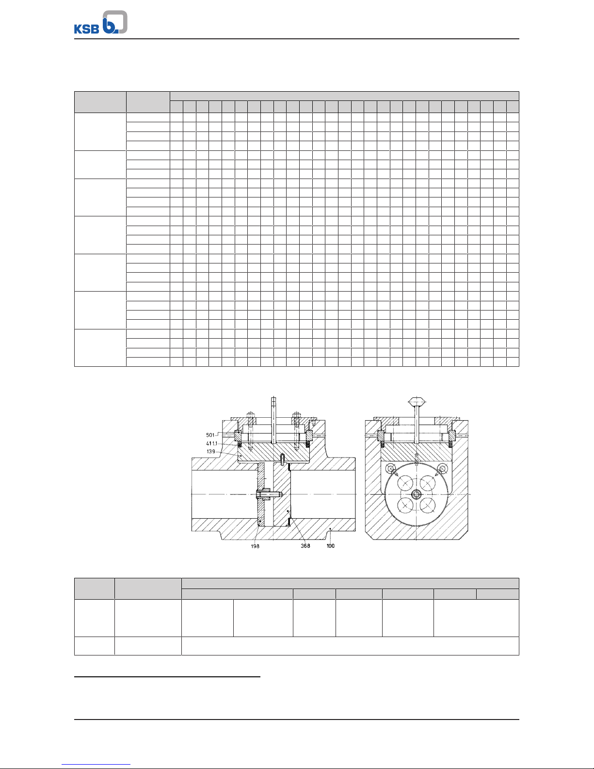
4 Valve Description
46 of 68
4.6.1.4 Pressure/temperature ratings
Table37: Permissible operating pressure [bar]
38)39)
Material Subseries [°C]
20
100
150
200
250
300
350
400
425
450
475
500
510
520
530
540
550
560
570
580
590
600
610
620
630
640
650
P250GH
1.0460
C 212 202 181 161 141 126 105 85 76 66 - - - - - - - - - - - - - - - - D 323 308 277 246 215 192 161 130 115 100 - - - - - - - - - - - - - - - - E 426 407 366 325 284 254 213 172 152 132 - - - - - - - - - - - - - - - - F 521 496 446 397 347 310 260 210 186 160 - - - - - - - - - - - - - - - - -
15NiCuMoNb5
1.6368
C 429 407 394 380 367 356 341 327 314 242 - - - - - - - - - - - - - - - - D 660 618 598 578 558 539 518 498 476 374 - - - - - - - - - - - - - - - - E 869 814 789 764 738 711 685 658 629 495 - - - - - - - - - - - - - - - - -
16Mo3
1.5415
C 268 237 214 192 177 151 147 141 140 136 134 94 66 52 42 - - - - - - - - - - - D 408 361 326 292 269 231 223 215 211 207 205 143 100 79 63 - - - - - - - - - - - E 539 478 432 386 356 304 294 284 279 275 269 189 132 104 83 - - - - - - - - - - - F 657 583 527 471 434 372 359 347 341 335 329 231 162 128 102 - - - - - - - - - - - -
13CrMo4-5
1.7335
C 268 243 228 213 202 187 177 167 162 157 155 138 118 95 79 61 49 - - - - - - - - - D 408 369 346 323 308 284 269 254 246 238 235 211 178 145 119 93 75 - - - - - - - - - E 539 488 457 427 407 376 355 335 325 315 310 277 236 191 158 124 100 - - - - - - - - - F 657 596 558 521 496 459 434 409 397 385 378 341 288 233 193 151 121 - - - - - - - - - -
10CrMo9-10
1.7380/
11CrMo9-10
1.7383
C 268 248 232 217 213 202 187 177 173 167 162 136 119 104 91 79 69 58 51 - - - - - - - D 408 377 354 331 323 308 284 269 262 254 246 207 181 158 138 119 104 89 78 - - - - - - - E 539 498 467 437 427 407 376 355 345 335 325 275 239 210 183 158 138 117 103 - - - - - - - F 657 608 570 533 521 496 459 434 422 409 397 335 292 255 223 193 168 144 126 - - - - - - - -
X10CrMoVNb9-1
1.4903
C - - - - - - - - - - - - - 245 225 204 185 166 148 131 116 102 89 78 67 59 50
D - - - - - - - - - - - - - 324 296 270 244 214 195 174 154 135 117 103 87 77 67
E - - - - - - - - - - - - - 470 429 391 353 316 283 251 221 197 170 148 126 112 96
F - - - - - - - - - - - - - 514 472 428 387 347 311 275 244 215 186 162 139 122 105
X10CrWMoVNb9-2
1.4901
C - - - - - - - - - - - - - - - - - - - 134 120 107 94 82 71 61 53
D - - - - - - - - - - - - - - - - - - - 201 180 160 142 123 106 92 79
E - - - - - - - - - - - - - - - - - - - 262 234 208 184 160 138 120 103
F - - - - - - - - - - - - - - - - - - - 314 281 250 221 192 166 144 124
4.6.1.5 Materials
Fig.3: VTS
Table38: Parts list
Part No. Description Materials for operating temperatures [°C] up to
450 530 550 570 600 650
100 Body
hard-faced with
17%Cr steel
P 250 GH
1.0460
15NiCuMoNb5
1.6368
16 Mo 3
1.5415
13 CrMo 4-5
1.7335
10CrMo9-10
1.7380/
11CrMo9-10
1.7383
X10CrMoVNb 9-1
1.4903
X10CrWMoVNb 9-2
1.4901
134 Blow-out attachment 16 Mo 3
1.5415
38) The valves are suitable for temperatures down to -10°C.
39) The test pressure is defined in accordance with the provisions of the technical codes PED2014/68/EU; DINEN12516-2 and
EN12266-1.
Page 47

4 Valve Description
47 of 68
Part No. Description Materials for operating temperatures [°C] up to
450 530 550 570 600 650
139 Bonnet P 250 GH
1.0460
15NiCuMoNb5
1.6368
16 Mo 3
1.5415
13 CrMo 4-5
1.7335
10CrMo9-10
1.7380/
11CrMo9-10
1.7383
X10CrMoVNb 9-1
1.4903
X10CrWMoVNb 9-2
1.4901
198 Plate 16 Mo 3
1.5415
368
40)
Blind plate
hard-faced with
CrNi steel
10CrMo9-10
1.7380/
11CrMo9-10
1.7383
15NiCuMoNb5
1.6368
10CrMo9-10
1.7380/
11CrMo9-10
1.7383
X10CrMoVNb 9-1
1.4903
X10CrWMoVNb 9-2
1.4901
411.1 Joint ring Pure graphite, capped with stainless steel
501 Segmental ring 10CrMo9-10
1.7380/
11CrMo9-10
1.7383
15NiCuMoNb5
1.6368
10CrMo9-10
1.7380/
11CrMo9-10
1.7383
X10CrMoVNb 9-1
1.4903
X10CrWMoVNb 9-2
1.4901
Typical applications
Free passage (blind plate removed) Closed passage (blind plate fitted)
40) Recommended spare parts
Page 48

4 Valve Description
48 of 68
4.6.1.6 Function
The line blind valve consists of body 100, bonnet 139 and blind plate 368 which shuts
off fluid flow in body 100. The seating faces of body 100 and blind plate 368 are
hard-faced. Blind plate 368 rests against plate 198 in the body seat via threaded pin
563 and nut 920.2.
The line blind valve is equipped with a pressure seal cover. The pressure inside the
body presses bonnet 139 against joint ring 411.1, which is supported by segmental
ring 501 via compression ring 500. Hexagon nuts 920.2, which are supported by cover
160 via studs 902.1, can be used to pre-load the pressure seal cover and to re-tighten
it at system pressure.
4.7 Scope of supply
▪ Valve
▪ One valve operating manual per packaging unit
4.8 Dimensions and weights
For dimensions and weights please refer to the type series booklet.
Page 49
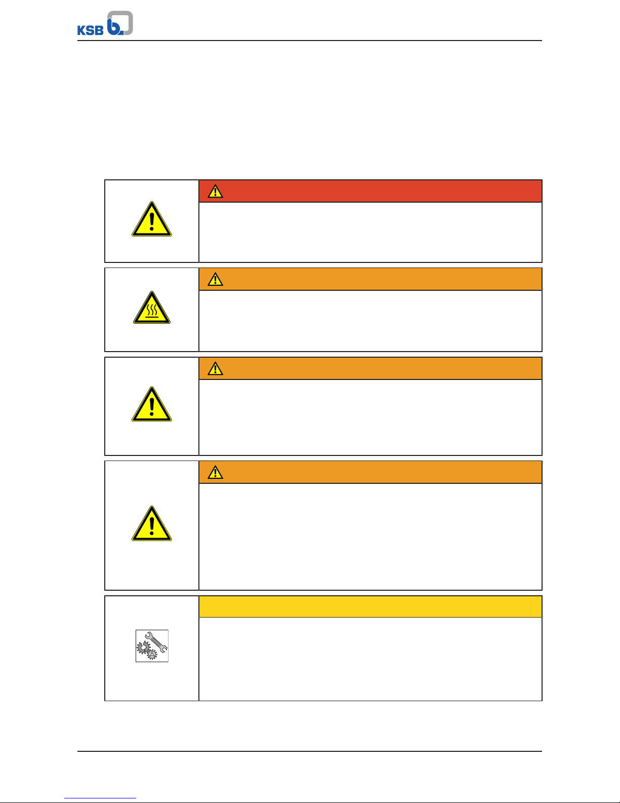
5 Installation at Site
49 of 68
5 Installation at Site
5.1 General information/Safety regulations
The operator ensures that maintenance, inspection and installation is performed by
authorised, qualified specialist personnel who are thoroughly familiar with the
manual.
The consultant, construction company or operator are responsible for positioning
and installing the valves. Planning errors and installation errors may impair the
reliable function of the valves and pose a substantial safety hazard.
DANGER
Dead-end valve
High-pressure hazard!
Risk of burns!
▷ Protect the valve against unauthorised and/or unintentional opening.
WARNING
Cold/hot piping and/or valve
Risk of thermal injury!
▷ Insulate the valve.
▷ Fit warning signs.
WARNING
Exposed rotating parts
Risk of injury!
▷ Do not touch rotating parts.
▷ When the equipment is in operation, perform any work with utmost caution.
▷ Take suitable precautions, e.g. provide safety covers.
WARNING
Impermissible loads resulting from operating conditions and valve-mounted
components, e.g. actuators
Leakage from or rupture of the valve body!
▷ Lay the piping in such a way that detrimental thrust and bending forces are
kept away from the valve body.
▷ Additional loads, e.g. traffic, wind or earthquakes are not taken into account
for standard variants; these require a separate design.
▷ Provide adequate support.
CAUTION
Condensation forming in air-conditioning systems, cooling systems and
refrigerating systems
Ice forming!
Actuating element blockage!
Damage due to corrosion!
▷ Insulate the valve to prevent diffusion.
Page 50

5 Installation at Site
50 of 68
CAUTION
Improper installation
Damage to the valve!
▷ Protect the body and body bonnet/cover from any impacts.
CAUTION
Outdoor installation
Damage due to corrosion!
▷ Protect the valve appropriately against moisture.
CAUTION
Painting of pipes
Impairment of the valve's function and loss of information!
▷ Protect stem and plastic components prior to applying paint.
▷ Protect printed name plates prior to applying paint.
CAUTION
Impermissible load
Damage to the actuating element!
▷ Do not use the valve as a foothold.
NOTE
Only use fasteners (e.g. to DINEN1515-4) and flange gaskets (e.g. to DINEN1514)
made of materials approved for the respective valve size. Always use all flange bolt
holes provided when connecting the valve to the piping. Refer to the type series
booklet for details on flange connections.
NOTE
For the valves to reach the documented Kv values, the flow direction must
correspond to the flow direction arrow.
NOTE
The mating flange faces must be clean and undamaged and the gaskets on the
mating flanges must be properly centred.
NOTE
Use an appropriate tool to evenly tighten the bolts crosswise, applying the
permissible torques.
5.2 Installation position and location
Gate valves For gate valves installed in horizontal pipes a vertical stem position is recommended
(handwheel or actuator on top, see position (a) shown below). Installation with the
stem in an inclined or horizontal position, e.g. as in vertical pipes (positions b, c, g, h),
is permitted. In this case, however, the actuator must be adequately supported at the
site. Avoid any installation positions with the actuator hanging downward (positions
d, e, f – risk of dirt ingress into the packing area via the back seat).
Page 51
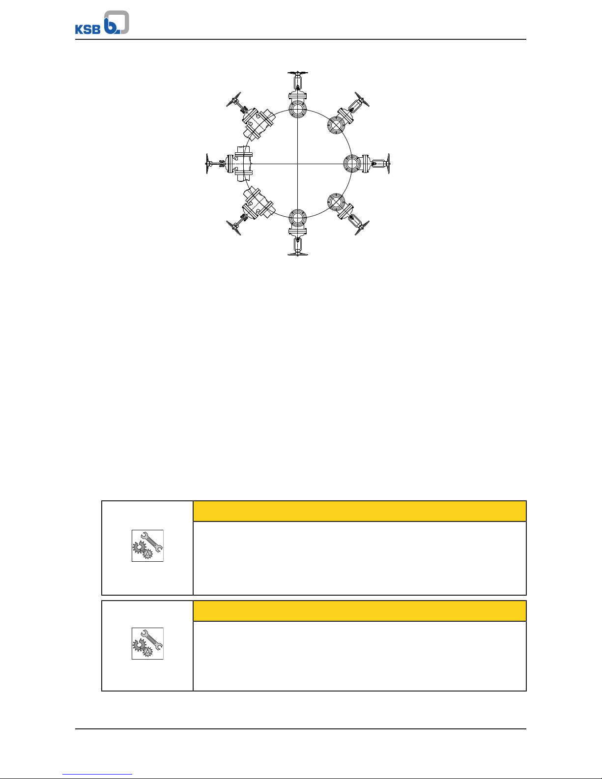
5 Installation at Site
51 of 68
(a)
(b)
(h)
(g)
(c)
(f)
(d)
(e)
Fig.4: Gate valve installation positions
Swing check valves Preferably install swing check valves in horizontal pipes. When installing them in
vertical pipes, make sure that the flow direction is upward. In the unpressurised
condition, the valve disc will then be closed by its own weight.
Line blind valve Line blind valves are mainly used for pressure testing the boiler or a run of piping in
a plant. For this purpose, the line blind valve must be installed in such a way that the
boiler pressure presses blind plate 368 against the body seat. When the shut-off
elements are not fitted, flow may pass through the valve in either direction.
When blind plate 368 is fitted, the protruding parallel pin 562.1 must point upwards.
This ensures that bonnet 139 can only be fitted with pointer 572 positioned
perpendicular to the flow direction. This indicates that the flow passage is closed.
When installing the line blind valve without the shut-off elements (normal operating
condition), make sure bonnet 139 is fitted so that the pointer is oriented in flow
direction. This indicates that the fluid passage is open.
Installation location The valve must not be fitted downstream of tees and level or three-dimensional
double bends.
5.3 Welding into the pipeline
Responsibility for welding the valve into the piping and for any heat treatment
required lies with the commissioned construction company or the plant operator.
CAUTION
Weld beads, scale and other impurities
Damage to the valve!
▷ Take suitable measures to protect the valve against impurities.
▷ Remove any impurities from the piping.
▷ If necessary, install a strainer.
CAUTION
Incorrect earthing during welding work on the piping
Damage to the valve (scorching)!
▷ Fully open the valve during welding. If the valve is equipped with a back seat,
run the obturator to an intermediate position.
▷ Never earth the electric welding equipment on the valve's functional parts.
Page 52

5 Installation at Site
52 of 68
CAUTION
Non-compliance with the max. permissible application temperature
Damage to the valve!
▷ Complete the weld seam in several steps to ensure that the temperature in the
middle of the body does not exceed the max. permissible application
temperature.
NOTE
For valves with socket weld ends, comply with the insertion depth given in the
applicable technical code. A gap between the pipe end and the base of the weld
socket prevents impermissible stress on the weld.
ü The valve is installed in accordance with the appropriate pipeline isometry.
ü Comply with the welding processes, filler metals and welding data laid down in
the welding plan.
1. Run the valve disc to the middle position prior to welding.
2. Verify that the butt weld ends are clean and undamaged.
3. Weld the valve into the piping in such a way that the valve/pipe welds are not
subjected to stresses, strains or torsion. During the welding process, ensure
constancy of the gap to the pipeline without radial offset.
4. When installing the valve with the stem in a horizontal position, adequately
support the weight of the actuator or gearbox.
5.4 Valves with actuator
Installation position and location (ðSection5.2,Page50)
Mounted actuators are factory-set and ready for operation. Changes to these
settings, e.g. changes to the set switching points of the limit positions, may impair
the valve's function and result in damage to the actuator, valve or the system.
DANGER
Unqualified personnel performing work on valves with actuator
Danger of death from electric shock!
▷ Ensure that the connection to the power supply and the process control system
is performed by a trained electrician.
▷ Observe regulations IEC60364 and, for explosion-proof models, EN60079.
DANGER
Work on valves with energy storage, e.g. spring mechanisms or compressed air
storage
Danger to life resulting from incorrect assembly
▷ Ensure that work on the actuator is performed by qualified specialist personnel.
▷ Mount/remove the actuator in accordance with the operating manual.
NOTE
If the valves are fitted with actuators, ensure that the actuator's operating manual
is also observed.
On valves with electric, pneumatic or hydraulic actuators, the actuator strokes/forces
must be limited.
Page 53

5 Installation at Site
53 of 68
Electric actuators Electric actuators are factory-set ready for operation and wired as follows:
▪ Valve "CLOSED": travel-dependent
▪ Valve "OPEN": travel-dependent
The wiring diagrams are located in the terminal boxes.
Pneumatic/hydraulic
actuators
For pneumatic or hydraulic actuators, the control pressures specified in the order
confirmation must be observed. Non-observance may damage the actuator.
If required, consult the manufacturer for closing and opening torques or actuating
forces.
5.5 Insulation
NOTE
Any insulation fitted on the valve must not impair the valve's function. The sealing
areas at the cover/bonnet joint and at the stem passage (gland packing) must be
directly accessible and visible.
Page 54

5 Installation at Site
54 of 68
5.6 Body pressure relief valve
Spring-loaded body
pressure relief valve (UGS)
DANGER
Valve blowing off downwards or upwards
High-pressure hazard!
Leakage of hot and/or toxic fluids!
Risk of burns!
▷ UGS and UGSV blow off downwards.
▷ UGSVA blows off upwards.
▷ Suitable measures must be taken to mark the hazardous area.
▷ Secure the hazardous area by fitting appropriate protective devices.
CAUTION
Incorrect installation of the body pressure relief valve
Damage to the valve!
▷ Do not weld the body pressure relief valve directly to connection branch 131.2;
connect it via pipe 710 in a vertical, upright position.
▷ Observe a distance of at least 200 mm outside the insulation when fitting the
body pressure relief valve.
NOTE
Use the body pressure relief valve only for the purpose of protecting the valve
body, never to protect piping systems, etc.
A body pressure relief valve is necessary if, with the gate valve closed, there is a
danger of the liquid trapped inside the valve body heating up and causing an
unacceptable pressure increase inside the valve. A warning sign is affixed to the yoke
arm near the name plate.
② 731
710 131.2
100 ③
①
Fig.5: UGS/UGSV body pressure relief valve on gate valve in pressure seal design
① 200mm minimum
distance
② Body pressure relief valve for both
flow directions
③ Insulation 100 Body
131.2 Connection branch 710 Pipe, not included in KSB’s scope of
supply
731 Pipe union
Page 55

5 Installation at Site
55 of 68
All gate valves with pressure seal bonnet manufactured by KSB are factory-supplied
with a closed connection branch 131.2 with connection dimensions Ø22 / Ø14.1
(suitable for pipe Ø21.3x3.6).
④
⑤
131.2
(ø 12,3)
ø 22
ø 14,1
ø 10
66
70
30°
Fig.6: Closed connection branch for body pressure relief valve
④ Welding groove ⑤ When connecting to pipe 710, cut here
and bevel the face to obtain a welding
groove.
131.2 Connection branch
To allow the installation to be matched to the structural requirements, the body
pressure relief valve is supplied with the gate valve, but not fitted.
CAUTION
Weld beads, scale and other impurities
Damage to the valve!
▷ Take suitable measures to protect the valve against impurities.
▷ Remove any impurities from the piping.
▷ If necessary, install a strainer.
Prior to welding, open closed connection branch 131.2 by sawing off the branch end
(the branch length should be 70mm) and bevel the face to obtain a welding groove.
CAUTION
Tripping of body pressure relief valve during commissioning
Damage to the seating faces due to foreign particles!
▷ Lock the body pressure relief valve in the closed position: The valve disc can be
pressed into the closed position via the rod by means of cover 160 fitted to
screw-type body 734, thus ensuring tight closure.
▷ Tapped holes are provided in screw-type body 734 for this purpose. The
relevant parts can be ordered at the supplying factory.
▷ The blocking device must be removed after the pressure test has been
completed.
Page 56

5 Installation at Site
56 of 68
1)
Blocking device
Spring-loaded body
pressure relief valve with
bursting disc (UGSV)
The body pressure relief valve with bursting disc is supplied fully assembled, i.e.
equipped with the bursting disc.
The installation is performed as described above.
Non-spring-loaded design
with bursting disc (UGSVA)
Always operate the UGSVA variant in combination with a lockable globe valve. Never
replace the bursting disc during operation. To do so, the pressure in the gate valve
must have been released.
The installation is performed as described above.
Page 57

6 Commissioning/Start-up/Shutdown
57 of 68
6 Commissioning/Start-up/Shutdown
6.1 Commissioning/Start-up
6.1.1 Prerequisites for commissioning/start-up
Before commissioning/start-up of the valve, ensure that the following requirements
are met:
▪ The material, pressure and temperature data on the valve complies with the
operating conditions of the piping. (ðSection4,Page14) .
▪ The material's chemical resistance and stability under load have been checked.
The nominal pressure classes only apply at room temperature. For values for higher
temperatures, refer to the pressure/temperature ratings tables.
(ðSection4,Page14) . Using the valve in conditions deviating from those specified
will lead to overload which the valves cannot withstand.
CAUTION
Welding beads, scale and other impurities in the piping
Damage to the valve!
▷ Remove any impurities from the piping.
▷ If necessary, install a strainer.
1. Thoroughly clean, flush and blow through all vessels, pipelines and connections
(especially of new installations).
2. Remove the valve's flange covers before installing it in the piping.
3. Check that the inside of the valve is free from any foreign objects. Remove any
foreign objects.
4. If required, install a strainer in the piping.
DANGER
Surge pressure/water hammer potentially occurring at high temperatures
Danger to life caused by burns or scalds!
▷ The max. permissible valve pressure must not be exceeded
(ðSection4,Page14) .
▷ Use valves made of nodular cast iron or steel.
▷ Operator shall provide general safety measures for the system.
CAUTION
Steam hammer potentially occurring at high temperatures
Damage to the valve!
▷ Drain the valve body completely.
▷ Specify drainage requirements in the purchase order.
▷ Unless otherwise agreed, drain branches shall be used exclusively for draining
the valve body.
Page 58
6 Commissioning/Start-up/Shutdown
58 of 68
CAUTION
Aggressive flushing and pickling agents
Damage to the valve!
▷ Match the cleaning operation mode and duration of flushing and pickling to
the body and seal materials used.
▷ Responsibility for the compatibility of the pickling media used and the pickling
procedure itself lies with the pickling company.
Functional check The following functions must be checked:
1. Check the shut-off function of the installed valve prior to commissioning/startup by opening and closing it several times.
2. Check gland packing 461 for leakage when it is subjected to full operating
pressure and operating temperature for the first time.
3. If gland follower 452 is loose, evenly re-tighten nuts 920.1/920.2.
4. Always tighten nuts 920.4/920.6 of the studs 902.2 pre-loading bonnet 139 and
joint ring 411 under operating conditions to ensure that leakage at the pressure
seal bonnet/cover, which might be caused by bonnet 139 sinking as pressure
inside body 100 decreases, is avoided.
5. Check the joint between the body and the bonnet/cover established by bolting
902.1/904/920.1 and joint ring 411.1 for tightness after the valve has been
subjected to load conditions or heated up for the first time.
6. To avoid stress or distortion, open the valve by approx. two full counterclockwise handwheel turns.
7. If bonnet/cover bolting 902.1/904/920.1 has loosened, evenly re-tighten it
crosswise.
NOTE
Re-tightening the bonnet/cover bolting is particularly important for valves operated
at temperatures exceeding 200°C.
Valves with actuators On valves with electric, pneumatic or hydraulic actuators, the actuator strokes/forces
must be limited.
DANGER
Unqualified personnel performing work on valves with actuator
Danger of death from electric shock!
▷ Ensure that the connection to the power supply and the process control system
is performed by a trained electrician.
▷ Observe regulations IEC60364 and, for explosion-proof models, EN60079.
WARNING
Incorrect connection to the mains
Damage to the mains network, short circuit!
▷ Observe the technical specifications of the local energy supply companies.
NOTE
If the valves are fitted with actuators, ensure that the actuator's operating manual
is also observed.
1. Check the available mains voltage against the data on the name plate of the
actuator.
2. Select an appropriate start-up method.
Page 59
6 Commissioning/Start-up/Shutdown
59 of 68
Electric actuators are factory-set ready for operation and wired as follows:
▪ Valve "CLOSED": travel-dependent
▪ Valve "OPEN": travel-dependent
The wiring diagrams are located in the terminal boxes.
For pneumatic or hydraulic actuators, the control pressures specified in the order
confirmation must be observed. Non-observance may damage the actuator.
If required, consult the manufacturer for closing and opening torques or actuating
forces.
Line blind valve The line blind valve is supplied in pre-assembled condition. After the pressure test the
shut-off elements (368 and 198) are dismantled in the following sequence:
DANGER
Valve under pressure
High-pressure hazard!
Leakage of hot and/or toxic fluids!
Risk of burns!
▷ Make sure that there is no system pressure on the inlet or outlet side of the
valve!
▷ Allow the valve to cool down so that the temperature is below the fluid's
vaporisation temperature in all areas in contact with the fluid in order to
effectively prevent any risk of scalding.
▷ Use appropriate spare parts and tools, even in emergencies.
1. Undo hexagon nut 920.1 and lift out cover 160.
2. Push bonnet 139 downwards and take segmental ring 501 out of the groove.
3. Lift out bonnet 139 complete with parts 500 and 411.
4. Loosen nut 920.2 and lift out shut-off assembly 368 and 198 connected by
threaded pin 563. Eyebolts 900 facilitate this step.
When re-installing shut-off elements 368 and 198 for another pressure test, it is
essential to do so in the reverse sequence of dismantling.
WARNING
Incorrect installation of the flow direction pointer
Leakage of hot and/or toxic fluids!
Damage to the system!
▷ Flow passage open = Pointer in flow direction
▷ Flow passage closed = Pointer perpendicular to the flow direction
▷ Having removed the shut-off assembly after the pressure test, make sure that
the bonnet is reassembled with the pointer pointing into the direction of flow.
When installing the pressure seal bonnet/cover ensure that parallel pin 562.1 is
aligned with the hole in bonnet 139.
Gate valves Shut-off valves are not suitable for regulating volume flow. Gate valves are used in
such a way that they are either fully open or fully closed. An intermediate position
(throttling function) is not permitted.
6.1.2 Valve actuation
NOTE
Viewed from above, the valve is closed by turning the handwheel in clockwise
direction, and opened by turning the handwheel in counter-clockwise direction.
Direction symbols are found on the top of the handwheel.
Page 60
6 Commissioning/Start-up/Shutdown
60 of 68
CAUTION
Excessively long idle periods
Damage to the valve!
▷ Check the function by opening and closing the valve at least once or twice a
year.
CAUTION
Use of levers
Damage to the valve as a result of excessive forces!
▷ Only actuate handwheel-operated valves by hand.
▷ Levers may only be used in exceptional cases and in compliance with the
following tables.
▷ Do not use levers in the area of the position indicator.
6.1.3 Information on the mechanical components
6.1.3.1 Moving parts
The valve/actuator combination comprises moving parts which are not fully enclosed.
Depending on the type and design, these include the following:
▪ Stem
▪ Stop
▪ Position switches
▪ Coupling
▪ Other force-transmitting equipment
Depending on the actuator type and design, further moving parts may be present,
e.g. emergency handwheels turning along with the actuator.
Valve commissioning/start-up is not permitted until both valve ends have been
connected to the pipeline and any risk of injuries can be ruled out.
6.1.3.2 Electric actuator overtravel
Depending on the mass to be accelerated, electric actuators may be subject to a
corresponding overtravel effect. Take into account this overtravel effect when setting
the actuator.
NOTE
If the valves are fitted with actuators, ensure that the actuator's operating manual
is also observed.
6.1.3.3 Self-locking function
As standard, the trapezoidal stem thread is self-locking. For special designs, e.g.
multiple threads, the self-locking function is taken over by the actuator assembly.
The self-locking effect may be reduced over time due to wear.
Page 61

6 Commissioning/Start-up/Shutdown
61 of 68
6.1.3.4 Uncontrolled movements
In the following cases, the valve's position may change in an uncontrolled manner
due to the system's pressure with resultant effects on the plant:
▪ Control failure
▪ Signal error
▪ Power supply failure during operation
▪ Incorrect actuator setting
▪ De-activation of the position switches in the actuator
Page 62

6 Commissioning/Start-up/Shutdown
62 of 68
6.2 Shutdown
6.2.1 Measures to be taken for shutdown
During prolonged shutdown periods, ensure that the following conditions are met:
1. Drain fluids which change their physical condition due to changes in
concentration, polymerisation, crystallisation, solidification, etc. from the piping.
2. If required, flush the piping with the valves fully opened.
6.2.2 Servicing/Maintenance
The valve has been designed to be largely maintenance-free. The materials of the
sliding parts have been selected for minimum wear.
NOTE
The user is responsible for defining appropriate intervals for checks and
maintenance, depending on the application of the valve.
NOTE
If several valves are serviced at the same time, take appropriate measures to
prevent the dismantled parts from getting mixed up.
The service life can be extended by taking the following measures:
▪ Checking the function by opening and closing the valve at least twice a year
▪ Lubricating the moving parts such as stem 200 and gland bolts (not for oxygen
valves) using appropriate lubricants (e.g. lubricants suitable for high
temperatures)
▪ Adding or replacing packing rings in gland packing 461 in time
▪ Re-tightening or replacing the bonnet/cover gasket 411.1 in time
Testing overhauled valves After reassembly and prior to commissioning/start-up, the valves must be subjected
to shell testing and leak testing to DINEN12266-1.
Body pressure relief valve
DANGER
Gate valve is not closed.
High-pressure hazard!
Leakage of hot and/or toxic fluids!
Risk of burns!
▷ Close the gate valve.
▷ Perform work with utmost care, making sure that all safety measures are
complied with.
Leakages at the seat caused by foreign objects between the body seat and valve disc
can be removed by briefly lifting rod 574 and allowing valve disc 350 to snap back
onto the seat. This is done by inserting two screw drivers on opposite sides into the
rod's groove.
If leakage cannot be eliminated, this indicates that the seating faces are damaged. If
this is the case, the body pressure relief valve needs to be replaced the next time that
the system is shut down.
Page 63
6 Commissioning/Start-up/Shutdown
63 of 68
CAUTION
Bursting discs are not marked
Risk of mixing up bursting discs!
▷ Always select the bursting disc according to the name plate in its packaging.
▷ Do not mix up bursting discs.
CAUTION
Incorrect installation position of bursting disc
Damage to the valve!
▷ Observe the installation position.
▷ The concave curvature must face the pressure side.
NOTE
Bursting discs are safety elements and must be handled with utmost care.
If the bursting disc needs replacing, the following steps must be observed:
ü Make sure the gate valve is not pressurised.
1. Remove sleeve 520 from pipe union 731.
2. Remove defective bursting disc 550.2. Do not damage the lead seal of the
spring-loaded body pressure relief valve.
3. Clean the sealing surfaces and ring 500.
4. Carefully take a new bursting disc 550.2 out of its packaging.
5. Insert bursting disc 550.2 into pipe union 731.
6. Place ring 500 onto the bursting disc.
7. Screw the complete body pressure relief valve into pipe union 731 and tighten
using a torque wrench.
PN ≤ 160: tightening torque 130 Nm
PN > 160: tightening torque as required
8. Remove the old name plate and replace with the new one.
9. Renew the paint dot at the point where rod 574 passes through screw-type
body 734.
Page 64

7 Servicing/Maintenance
64 of 68
7 Servicing/Maintenance
7.1 Safety regulations
The operator ensures that maintenance, inspection and installation is performed by
authorised, qualified specialist personnel who are thoroughly familiar with the
manual.
DANGER
Valve under pressure
Risk of injury!
Leakage of hot and/or toxic fluids!
Risk of burns!
▷ The valve and its surrounding system must be depressurised prior to any
maintenance and installation work.
▷ If the bellows are defective and fluid escapes, ensure the valve is depressurised.
▷ Ensure the valve is depressurised before removing any drain, opening or vent
plugs.
▷ Allow the valve to cool down so that the temperature is below the fluid's
vaporisation temperature in all areas in contact with the fluid in order to
effectively prevent any risk of scalding.
▷ Never vent the valve by removing the bonnet/cover bolting or gland packing.
▷ Use appropriate spare parts and tools, even in emergencies.
WARNING
Fluids, consumables and supplies which are hot and/or pose a health hazard
Risk of injury!
▷ Observe all relevant laws.
▷ When draining the fluid take appropriate measures to protect persons and the
environment.
▷ Decontaminate valves used for handling fluids posing a health hazard.
NOTE
Before removing the valve from the piping, ensure that the pipe has been taken
out of service and released for repair/maintenance work.
A regular maintenance schedule will help avoid expensive repairs and contribute to
trouble-free, reliable operation of the valve with a minimum of maintenance
expenditure and work.
NOTE
All maintenance, service and installation work can be carried out by KSB Service or
authorised workshops. For contact details please refer to the enclosed "Addresses"
booklet or visit "www.ksb.com/contact" on the Internet.
Never use force when dismantling and reassembling the valve.
Page 65
8 Trouble-shooting
65 of 68
8 Trouble-shooting
WARNING
Improper remedial work on the valve
Risk of injury!
▷ For any work performed in order to remedy faults on the valve observe the
relevant information given in this operating manual and/or the product
literature provided by the accessories manufacturers.
If problems occur that are not described in the following table, consultation with the
KSB customer service is required.
Table39: Trouble-shooting
Problem Possible cause Remedy
Leakage at the seat ▪ Contaminations or solids in the
fluid
▪ Erosion, corrosion or abrasion
▪ Excessive loads from pipeline
forces or thermal stresses
1. Dismantle bonnet/cover bolting
902.1/920.1.
2. Rework the seating faces of valve
disc and body using a suitable reseating tool.
3. Continue re-seating until the
seating faces exhibit a consistently
smooth and even ring.
Leakage at the gland packing Unevenly tightened gland packing 1. Re-tighten hexagon nuts 920/920.2
as specified in the manual.
Defective gland packing 1. Undo hexagon nuts 920/920.2.
2. Lift gland follower 452.
3. Clean the gland packing chamber.
4. Insert split packing rings in such a
manner that the cut ends of the
rings are offset by between 120°
and 180°.
Leakage at bonnet/body joint or
cover/body joint (bolted bonnet/
cover design)
Unevenly tightened bonnet/cover
bolts
1. Re-tighten bonnet/cover bolting
902.1/920.1 as specified in the
manual.
Defective bonnet/cover gasket 1. Dismantle bonnet/cover bolting
902.1/920.1.
2. Clean sealing surfaces.
3. Replace joint ring 411.
The tightening torques must be
observed.
Leakage at the bonnet/body joint or
cover/body joint (for pressure seal
design)
Unevenly tightened hexagon head
bolts
1. Re-tighten hexagon head bolts
901.1/920.1 as specified in the
manual.
Defective joint ring 1. Remove pressure seal bonnet/cover.
2. Clean sealing surfaces.
3. Replace joint ring 411.1.
The tightening torques must be
observed.
Page 66

9 EU Declaration of Conformity
66 of 68
9 EU Declaration of Conformity
9.1 EU Declaration of Conformity for STAAL40, STAAL100, AKG-A/AKGS-A,
AKR/AKRS, ZTS, ZRS, VTS
Herewith we, KSB SE & Co. KGaA
Bahnhofplatz 1
91257 Pegnitz
Registered office: Frankenthal (Pfalz)
Germany
declare that the product:
Gate valves
STAAL40 AKD/AKDS PN10 - 40 DN50 - 1400
STAAL100 AKD/AKDS PN63 - 100 DN50 - 800
AKG-A/AKGS-A PN63 - 160 DN 80 - 300
ZTS Pmax. = 600 bar DN50 - 800
Swing check valves
STAAL 40 AKK/AKKS PN10 - 40 DN80 - 400
STAAL 100 AKK/AKKS PN63 - 100 DN80 - 400
AKR/AKRS PN63 - 160 DN80 - 300
ZRS Pmax. = 600 bar DN 50 - 800
Line blind valve
VTS Pmax. = 600 bar DN200 - 500
Body pressure relief valve
UGS/UGSV/UGSVA ≥ PN40 DN 15
satisfies the safety requirements laid down in the Pressure Equipment Directive 2014/68/EU.
Codes applied:
AD2000 code of the German Pressure Vessel Society
Suitable for:
Fluids in Groups 1 and 2
Conformity assessment procedure:
Module H
Name and address of the notified body responsible for approval and surveillance:
TÜV SÜD Industrie Service GmbH
Westendstraße 199
80686 München (Germany)
Identification number of the notified body:
0036
For models with by-pass, the assembly's conformity with the Pressure Equipment Directive 2014/68/EU is confirmed.
The EU Declaration of Conformity was issued in/on:
Frankenthal, 1 February 2018
Wolfgang Glaub Dr. Christopher Lange
Vice President Integrated Management Germany Head of Corporate Unit Valves
Page 67

Index
67 of 68
Index
C
CE marking14
Commissioning57
D
Design16, 19, 23, 26, 34, 36, 41, 45
Design details
AKG-A/AKGS-A23
AKR/AKRS39
STAAL 100 AKD/AKDS19
STAAL 100 AKK/AKKS36
STAAL 40 AKD/AKDS16
STAAL 40 AKK/AKKS34
VTS45
ZRS41
ZTS26
Disposal13
E
Event of damage6
F
Faults
Causes and remedies65
Fluids in Group 114
Fluids in Group 214
Function
AKG-A/AKGS-A15
AKR/AKRS33
STAAL 100 AKK/AKKS33
STAAL 40 AKK/AKKS33
UGS32
VTS48
ZRS33
ZTS15
I
Intended use8
K
Key to safety symbols/markings7
M
Maintenance62, 64
Marking14
Materials
AKG-A/AKGS-A25
AKR/AKRS40
STAAL 100 AKD/AKDS21
STAAL 100 AKK/AKKS37
STAAL 40 AKD/AKDS18
STAAL 40 AKK/AKKS35
UGS31
VTS46
ZRS44
ZTS29
O
Operating data
AKG-A/AKGS-A23
AKR/AKRS39
STAAL 100 AKD/AKDS19
STAAL 100 AKK/AKKS36
STAAL 40 AKD/AKDS16
STAAL 40 AKK/AKKS34
VTS45
ZRS41
ZTS26
Operating limits8
Other applicable documents6
P
Personnel8
Pressure Equipment Directive 2014/68/EU14
Pressure/temperature ratings
AKG-A/AKGS-A24
AKR/AKRS40
STAAL 100 AKD/AKDS20
STAAL 100 AKK/AKKS37
STAAL 40 AKD/AKDS17
STAAL 40 AKK/AKKS35
VTS46
ZRS43
ZTS27
Q
Qualification8
R
Return to supplier13
S
Safety7
Safety awareness9
Scope of supply48
Shutdown62
Storage12
T
Transport11
W
Warnings7
Warranty claims6
Page 68

KSB SE & Co. KGaA
Johann-Klein-Straße 9 • 67227 Frankenthal (Germany)
Tel. +49 6233 86-0
www.ksb.com
0570.81/16-EN
 Loading...