

KSB STAAL 40 AKD, STAAL 100 AKGS-A, STAAL 100 ZTS, STAAL 40 AKKS, STAAL 100 AKK Operating Manual
...
STAAL 40 AKD/AKDS, STAAL 100 AKD/AKDS,
AKG-A/AKGS-A, ZTS,
STAAL 40 AKK/AKKS, STAAL 100 AKK/AKKS,
AKR/AKRS, ZRS, VTS, UGS
Operating Manual

Legal information/Copyright
Operating Manual
Original operating manual
All rights reserved. The contents provided herein must neither be distributed, copied, reproduced,
edited or processed for any other purpose, nor otherwise transmitted, published or made available to a
third party without the manufacturer's express written consent.
Subject to technical modification without prior notice.
© KSB SE & Co. KGaA, Frankenthal 04/10/2018

Contents
3 of 68
Contents
Glossary .................................................................................................................................................. 5
1 General.................................................................................................................................................... 6
1.1 Principles ...........................................................................................................................................................6
1.2 Target group.....................................................................................................................................................6
1.3 Other applicable documents............................................................................................................................6
1.4 Symbols .............................................................................................................................................................6
2 Safety...................................................................................................................................................... 7
2.1 Key to safety symbols/markings.......................................................................................................................7
2.2 General..............................................................................................................................................................7
2.3 Intended use .....................................................................................................................................................8
2.3.1 Prevention of foreseeable misuse.......................................................................................................8
2.4 Personnel qualification and training...............................................................................................................8
2.5 Consequences and risks caused by non-compliance with this manual .........................................................8
2.6 Safety awareness ..............................................................................................................................................9
2.7 Safety information for the operator/user.......................................................................................................9
2.8 Safety information for maintenance, inspection and installation ................................................................9
2.9 Unauthorised modes of operation..................................................................................................................9
3 Transport/Temporary Storage/Disposal............................................................................................. 11
3.1 Checking the condition upon delivery..........................................................................................................11
3.2 Transport.........................................................................................................................................................11
3.3 Storage/preservation......................................................................................................................................12
3.4 Return to supplier...........................................................................................................................................13
3.5 Disposal ...........................................................................................................................................................13
4 Valve Description ................................................................................................................................. 14
4.1 General description ........................................................................................................................................14
4.2 Marking...........................................................................................................................................................14
4.3 Gate Valves .....................................................................................................................................................14
4.3.1 Function of gate valves with bolted bonnet....................................................................................14
4.3.2 Function of gate valves with pressure seal bonnet .........................................................................15
4.3.3 Gate Valves to DIN/EN with Bolted Bonnet .....................................................................................16
4.3.4 Gate Valves to DIN/EN in Pressure Seal Design ................................................................................23
4.4 Body Pressure Relief Valve.............................................................................................................................29
4.4.1 UGS .....................................................................................................................................................29
4.5 Swing check valves .........................................................................................................................................33
4.5.1 Function of swing check valves with bolted cover ..........................................................................33
4.5.2 Function of swing check valves with pressure seal cover ................................................................33
4.5.3 Swing Check Valves with Bolted Cover ............................................................................................34
4.5.4 Swing check valves with pressure seal cover....................................................................................39
4.6 Line Blind Valve ..............................................................................................................................................45
4.6.1 VTS ......................................................................................................................................................45
4.7 Scope of supply...............................................................................................................................................48
4.8 Dimensions and weights ................................................................................................................................48
5 Installation at Site................................................................................................................................ 49
5.1 General information/Safety regulations .......................................................................................................49
5.2 Installation position and location..................................................................................................................50
5.3 Welding into the pipeline..............................................................................................................................51
5.4 Valves with actuator.......................................................................................................................................52
5.5 Insulation ........................................................................................................................................................53
5.6 Body pressure relief valve ..............................................................................................................................54
6 Commissioning/Start-up/Shutdown................................................................................................... 57
6.1 Commissioning/Start-up.................................................................................................................................57
6.1.1 Prerequisites for commissioning/start-up .........................................................................................57

Contents
4 of 68
6.1.2 Valve actuation ..................................................................................................................................59
6.1.3 Information on the mechanical components...................................................................................60
6.2 Shutdown........................................................................................................................................................62
6.2.1 Measures to be taken for shutdown ................................................................................................62
6.2.2 Servicing/Maintenance ......................................................................................................................62
7 Servicing/Maintenance........................................................................................................................ 64
7.1 Safety regulations...........................................................................................................................................64
8 Trouble-shooting.................................................................................................................................. 65
9 EU Declaration of Conformity............................................................................................................. 66
9.1 EU Declaration of Conformity for STAAL40, STAAL100, AKG-A/AKGS-A, AKR/AKRS, ZTS, ZRS, VTS ......66
Index ..................................................................................................................................................... 67

Glossary
5 of 68
Glossary
Pressure Equipment Directive (PED)
The 2014/68/EU Directive sets out the
requirements to be met by pressure equipment
intended to be placed on the market in the
European economic area.
Technical literature
Refer to the product catalogue for the technical
literature on our products at www.ksb.com.
1 General
6 of 68
1 General
1.1 Principles
This operating manual is supplied as an integral part of the type series and variants
indicated on the front cover.
The manual describes the proper and safe use of this equipment in all phases of
operation.
In the event of damage, immediately contact your nearest KSB sales organisation
responsible to maintain the right to claim under warranty.
1.2 Target group
This operating manual is aimed at the target group of trained and qualified specialist
technical personnel.
1.3 Other applicable documents
Table1: Overview of other applicable documents
Document Contents
Type series booklet Description of the valve
Flow characteristics
1)
Information on Kv and zeta values
General assembly drawing
2)
Sectional drawing of the valve
Sub-supplier product literature3)Operating manuals and other product literature
for the accessories
Observe the relevant manufacturer's product literature for the accessories.
1.4 Symbols
Table2: Symbols used in this manual
Symbol Description
✓ Conditions which need to be fulfilled before proceeding with the
step-by-step instructions
⊳ Safety instructions
⇨
Result of an action
⇨ Cross-references
1.
2.
Step-by-step instructions
Note
Recommendations and important information on how to handle
the product
1) If any
2) If inclusion in the scope of supply has been agreed; otherwise refer to the type series booklet.
3) If inclusion in the scope of supply has been agreed.
2 Safety
7 of 68
2 Safety
!
DANGER
All the information contained in this section refers to hazardous situations.
In addition to the present general safety information the action-related safety
information given in the other sections must be observed.
2.1 Key to safety symbols/markings
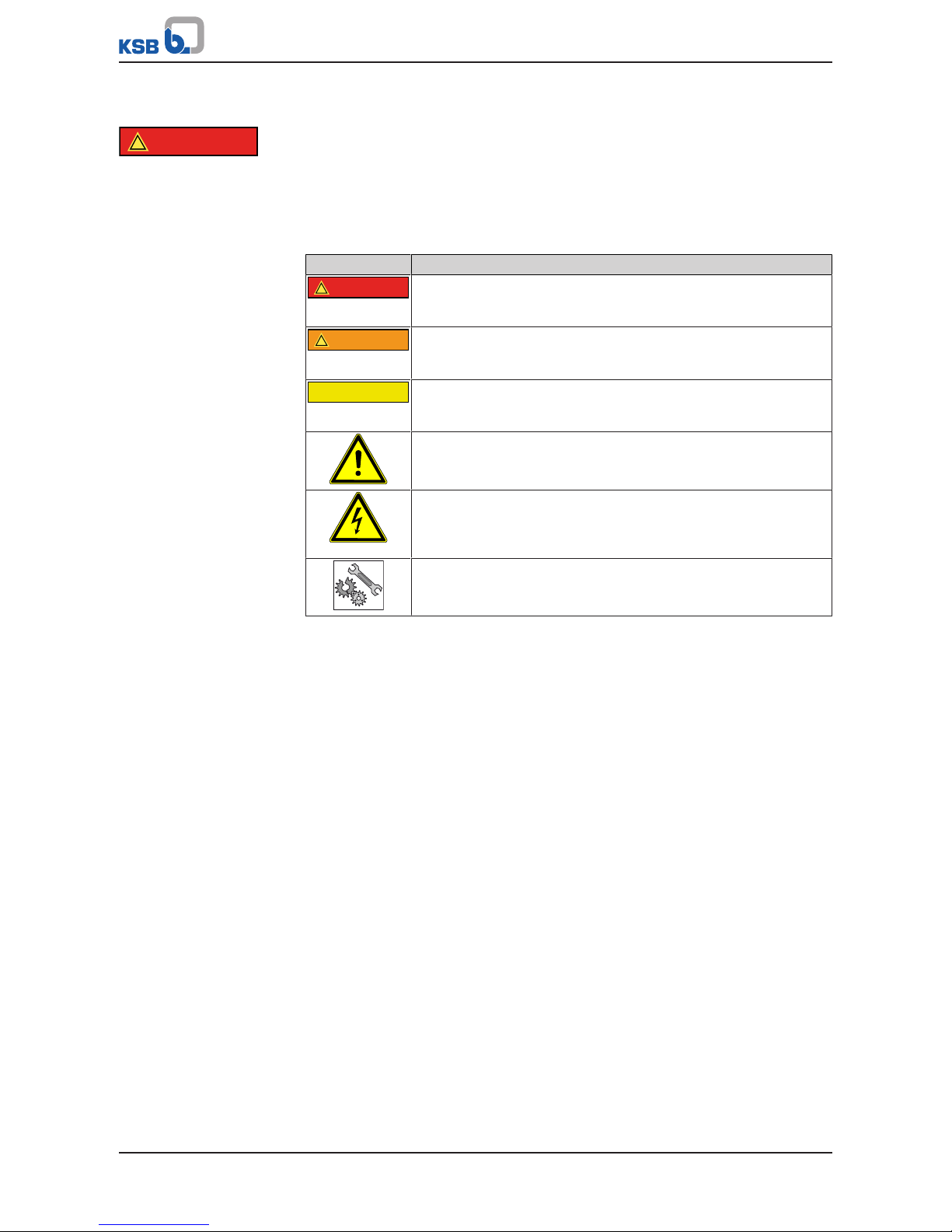
Table3: Definition of safety symbols/markings
Symbol Description
!
DANGER
DANGER
This signal word indicates a high-risk hazard which, if not avoided,
will result in death or serious injury.
!
WARNING
WARNING
This signal word indicates a medium-risk hazard which, if not
avoided, could result in death or serious injury.
CAUTION
CAUTION
This signal word indicates a hazard which, if not avoided, could
result in damage to the machine and its functions.
General hazard
In conjunction with one of the signal words this symbol indicates a
hazard which will or could result in death or serious injury.
Electrical hazard
In conjunction with one of the signal words this symbol indicates a
hazard involving electrical voltage and identifies information about
protection against electrical voltage.
Machine damage
In conjunction with the signal word CAUTION this symbol indicates
a hazard for the machine and its functions.
2.2 General
This operating manual contains general installation, operating and maintenance
instructions that must be observed to ensure safe operation of the system and
prevent personal injury and damage to property.
The safety information in all sections of this manual must be complied with.
The operating manual must be read and understood by the responsible specialist
personnel/operators prior to installation and commissioning.
The contents of this operating manual must be available to the specialist personnel
at the site at all times.
Information and markings attached directly to the product must always be complied
with and kept in a perfectly legible condition at all times. This applies to, for
example:
▪ Flow direction arrow
▪ Manufacturer
▪ Type designation
▪ Nominal pressure, nominal size
▪ Year of construction
▪ Body material
The operator is responsible for ensuring compliance with all local regulations not
taken into account in this operating manual.
The design, manufacture and the testing of the valve are subject to a QM system to
DINENISO9001 as well as the current European Pressure Equipment Directive.
European Pressure Equipment Directive (PED) Compliance with these requirements,
however, is based on normal, predominantly static loading.

2 Safety
8 of 68
Bear in mind that valves exposed to creep-rupture conditions have a limited service
life and have to meet the applicable regulations stipulated in the technical codes.
In the case of customised special variants, further restrictions may apply with regard
to the operating mode and service life. Refer to the relevant sales documentation for
applicable limitations.
This operating manual does not take into account:
▪ Any eventualities or incidents occurring during installation performed by the
customer, operation and maintenance.
▪ Local regulations; the operator must ensure that such regulations are strictly
observed by all, including the personnel called in for installation.
2.3 Intended use
▪ Only operate valves which are in perfect technical condition.
▪ Do not operate the valve in partially assembled condition.
▪ Only use the valve for fluids specified in the product literature. Take the material
variant into account.
▪ Only operate the valve within the operating limits described in the other
applicable documents.
▪ The valve's design and rating are based on predominantly static loading in
accordance with the codes applied. Consult the manufacturer if the valve is
subjected to dynamic loads or any other additional influences.
▪ Consult the manufacturer about any other modes of operation not described in
the product literature.
▪ Do not use the valve as a foothold.
2.3.1 Prevention of foreseeable misuse
▪ Never exceed the permissible application and operating limits specified in the
product literature regarding pressure, temperature, etc.
▪ Observe all safety information and instructions in this manual.
2.4 Personnel qualification and training
All personnel involved must be fully qualified to transport, install, operate, maintain
and inspect the product this manual refers to and be fully aware of the interaction
between the valve and the system.
The responsibilities, competence and supervision of all personnel involved in
transport, installation, operation, maintenance and inspection must be clearly
defined by the operator.
Deficits in knowledge must be rectified by means of training and instruction
provided by sufficiently trained specialist personnel. If required, the operator can
commission the manufacturer/supplier to train the personnel.
Hands-on training at the valve must always be supervised by specialist technical
personnel.
2.5 Consequences and risks caused by non-compliance with this manual
▪ Non-compliance with these operating instructions will lead to forfeiture of
warranty cover and of any and all rights to claims for damages.
▪ Non-compliance can, for example, have the following consequences:
– Hazards to persons due to electrical, thermal, mechanical and chemical
effects and explosions
– Failure of important product functions
– Failure of prescribed maintenance and servicing practices
– Hazard to the environment due to leakage of hazardous substances

2 Safety
9 of 68
2.6 Safety awareness
In addition to the safety information contained in this manual and the intended use,
the following safety regulations shall be complied with:
▪ Accident prevention, health regulations and safety regulations
▪ Explosion protection regulations
▪ Safety regulations for handling hazardous substances
▪ Applicable standards, directives and laws
2.7 Safety information for the operator/user
Actuator-operated valves are intended for use in areas which cannot be accessed by
unauthorised persons. Operation of these valves in areas which can be accessed by
unauthorised persons is only permitted if appropriate protective devices are fitted at
the site. This must be ensured by the operator.
▪ Fit protective equipment (e.g. contact guards) supplied by the operator for hot,
cold or moving parts, and check that the equipment functions properly.
▪ Do not remove any protective equipment (e.g. contact guards) during operation.
▪ Provide the personnel with protective equipment and make sure it is used.
▪ Contain leakages (e.g. at the stem seal) of hazardous fluids (e.g. explosive, toxic,
hot) so as to avoid any danger to persons and the environment. Adhere to all
relevant laws.
▪ Eliminate all electrical hazards. (In this respect refer to the applicable national
safety regulations and/or regulations issued by the local energy supply
companies.)
2.8 Safety information for maintenance, inspection and installation
▪ Modifications or alterations of the valve require the manufacturer's prior
consent.
▪ Use only original spare parts or parts/components authorised by the
manufacturer. The use of other parts/components can invalidate any liability of
the manufacturer for resulting damage.
▪ The operator ensures that maintenance, inspection and installation is performed
by authorised, qualified specialist personnel who are thoroughly familiar with
the manual.
▪ Carry out work on the valve during standstill only.
▪ The valve body must have cooled down to ambient temperature.
▪ The pressure in the valve body must have been released and the valve must have
been drained.
▪ When taking the valve out of service always adhere to the procedure described
in the manual.
▪ Decontaminate valves which handle fluids posing a health hazard.
▪ Protect the valve body and body bonnet/cover from any impacts.
▪ As soon as the work has been completed, re-install and re-activate any safety-
relevant devices and protective devices. Before returning the product to service,
observe all instructions on commissioning. (ðSection6.1,Page57)
2.9 Unauthorised modes of operation
Never operate the valve outside the limits stated in the data sheet and in this
operating manual.
The warranty relating to the operating reliability and safety of the valve supplied is
only valid if the valve is used in accordance with its intended use.
(ðSection2.3,Page8)
Shut-off valves are not suitable for regulating volume flow.

2 Safety
10 of 68
Gate valves are used in such a way that they are either fully open or fully closed. An
intermediate position (throttling function) is not permitted.
3 Transport/Temporary Storage/Disposal
11 of 68
3 Transport/Temporary Storage/Disposal
3.1 Checking the condition upon delivery
1. On transfer of goods, check each packaging unit for damage.
2. In the event of in-transit damage, assess the exact damage, document it and
notify KSB or the supplying dealer and the insurer about the damage in writing
immediately.
3.2 Transport
Always close the valve manually before transporting it. The valve is delivered ready
for operation and its line connection ports may still be closed with caps, if applicable.
Original spare parts are only ready for operation following assembly/installation and
subsequent shell and leak testing of the valve.
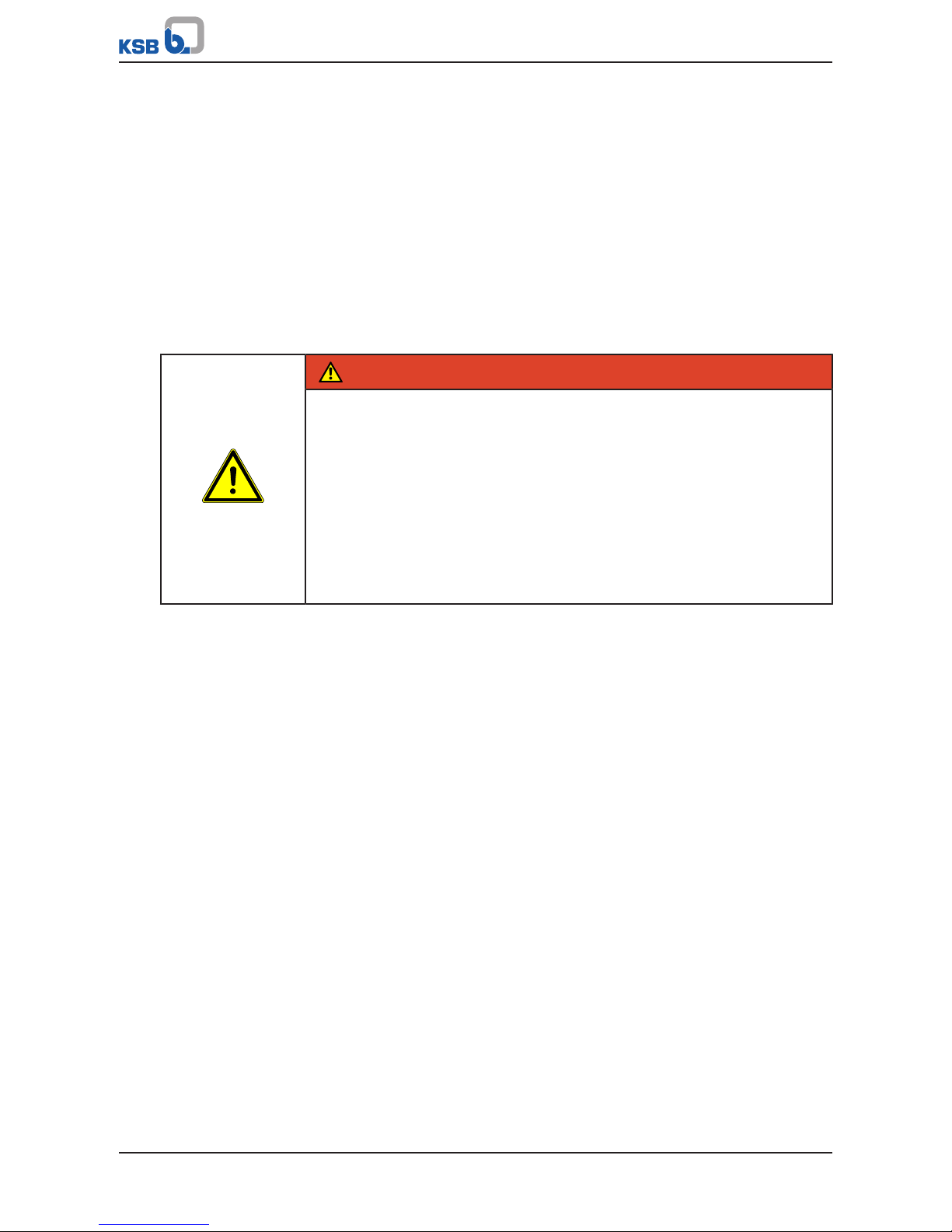
DANGER
The valve could slip out of the suspension arrangement
Danger to life from falling parts!
▷ Only transport the valve in the specified position.
▷ Never suspend the valve from its handwheel.
▷ Pay attention to the weight data and the centre of gravity.
▷ Observe the applicable local accident prevention regulations.
▷ Use suitable, permitted lifting accessories.
▷ Transport devices (if any) on the actuator may not be suitable for being
attached to a suspension arrangement in order to transport the valve/actuator
assembly. Refer to the actuator operating manual for the permissible loads.
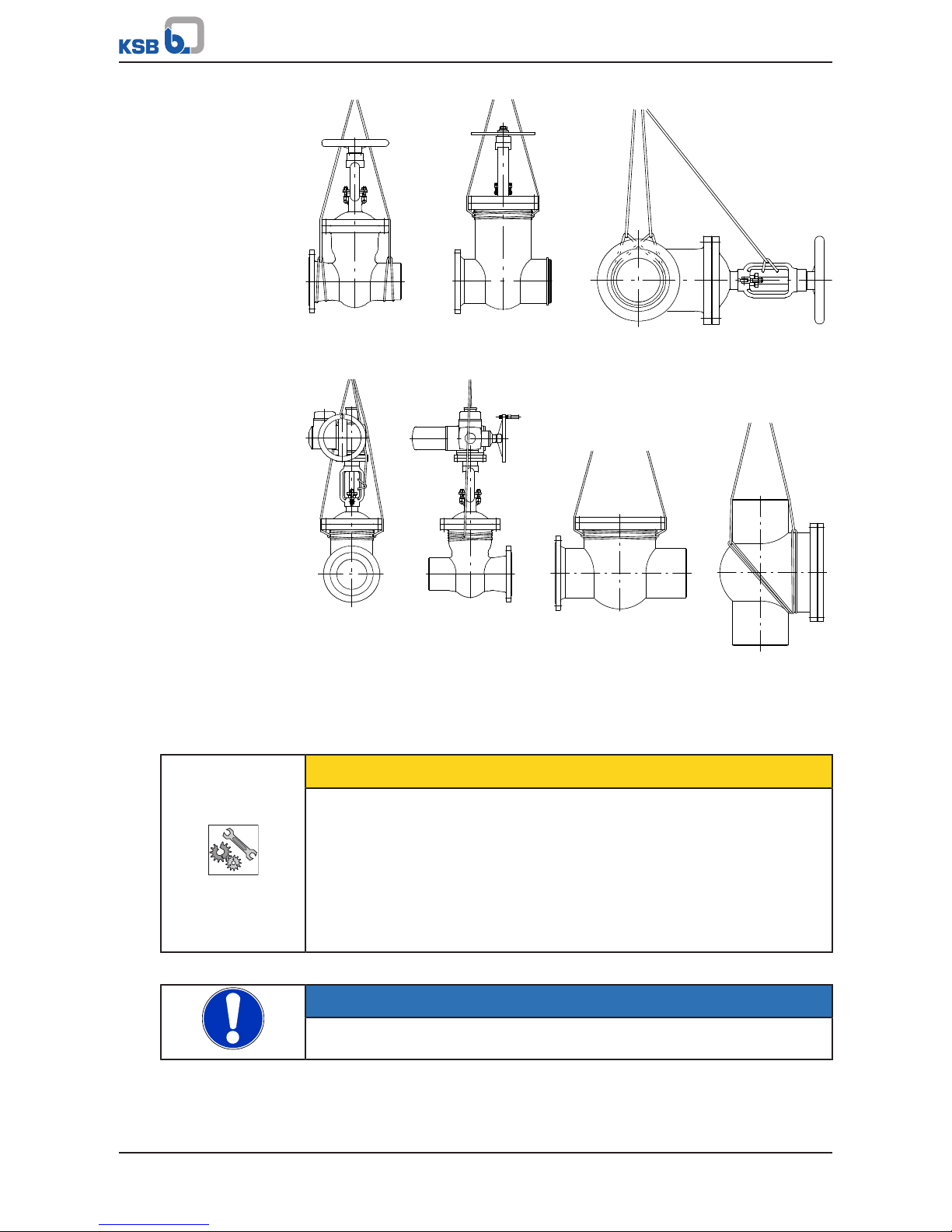
To transport the valve, suspend it from the lifting tackle as illustrated.
3 Transport/Temporary Storage/Disposal
12 of 68
Fig.1: Transporting the valve
3.3 Storage/preservation
If commissioning is to take place some time after delivery, we recommend that the
following measures be taken for storing the valve:
CAUTION
Incorrect storage
Damage to the valve due to dirt, corrosion, moisture and/or frost!
▷ Store the valve in a dust- and vibration-free, frost-proof room where the
atmospheric humidity is as constant as possible (use suitable caps or film for
protection).
▷ Close the valve using little force and store in the closed position.
▷ Protect the valve from contact with solvents, lubricants, fuels or other
chemicals.
If properly stored indoors, the equipment is protected for a maximum of 12 months.
NOTE
For actuated valves, also observe the actuator's operating manual.
3 Transport/Temporary Storage/Disposal
13 of 68
3.4 Return to supplier
1. Drain the valve as described in the manual.
2. Flush and clean the valve, particularly if it has been used for handling noxious,
explosive, hot or other hazardous fluids.
3. If the valve has handled fluids whose residues could lead to corrosion damage in
the presence of atmospheric humidity or could ignite upon contact with oxygen
also neutralise the valve and blow through with anhydrous inert gas to ensure
drying.
4. When returning valves used for handling Fluids in Group1 always complete and
enclose a certificate of decontamination.
Indicate any safety measures and decontamination measures taken.
NOTE
If required, a blank certificate of decontamination can be downloaded from the
following web site: www.ksb.com/certificate_of_decontamination
3.5 Disposal
WARNING
Fluids handled, consumables and supplies which are hot or pose a health hazard
Hazard to persons and the environment!
▷ Collect and properly dispose of flushing fluid and any residues of the fluid
handled.
▷ Wear safety clothing and a protective mask if required.
▷ Observe all legal regulations on the disposal of fluids posing a health hazard.
1. Dismantle the valve.
Collect greases and other lubricants during dismantling.
2. Separate and sort the valve materials, e.g. by:
- Metals
- Plastics
- Electronic waste
- Greases and other lubricants
3. Dispose of materials in accordance with local regulations or in another
controlled manner.
4 Valve Description
14 of 68
4 Valve Description
4.1 General description
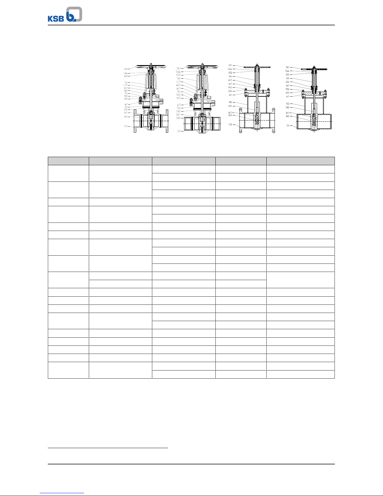
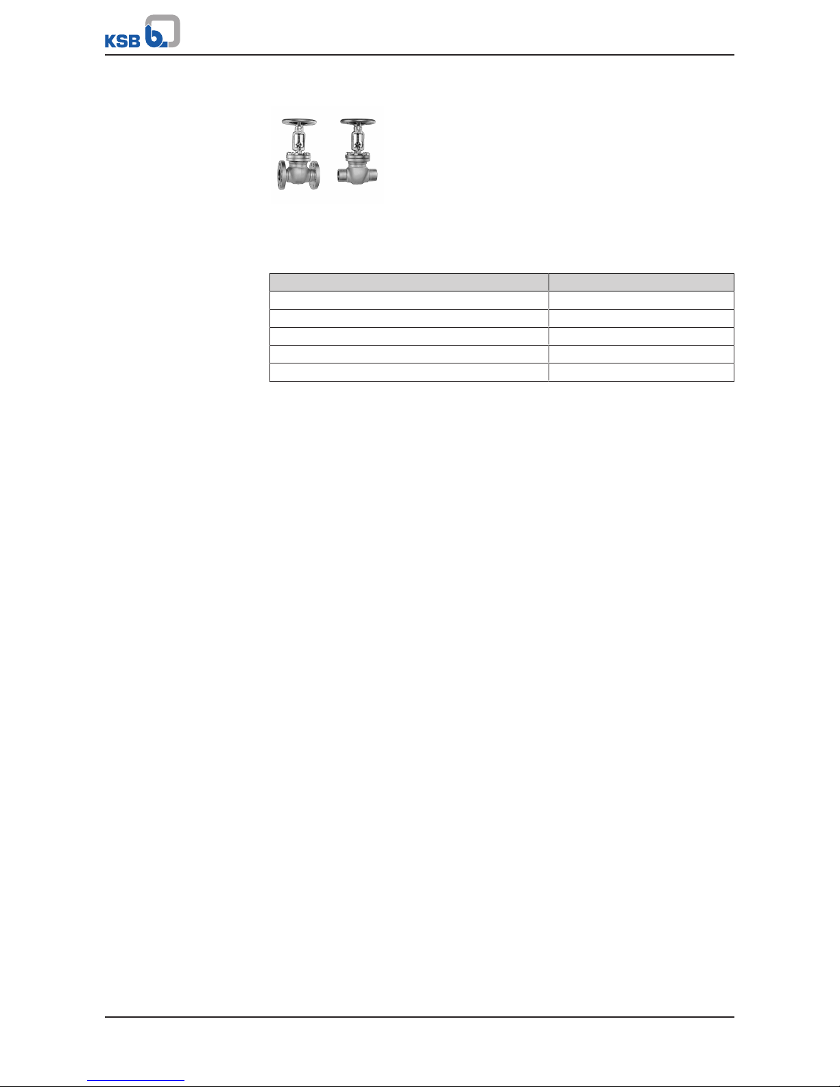
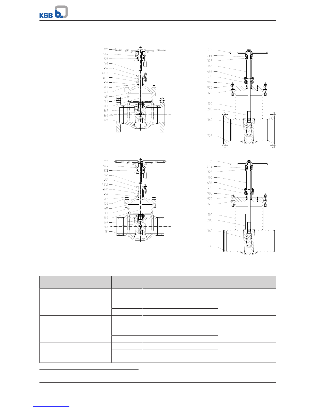
The sectional drawings below provide examples of the general design/configuration
of the valve. For additional and more detailed information, refer to the respective
type series booklet.
4.2 Marking
Table4: General marking
Nominal size DN ...
Nominal pressure class and/or max. permissible pressure/
temperature
PN ... / ... bar / ...
°C
Manufacturer KSB
Type series/model and/or order number NORI...
Year of construction 20..
Material .......
Flow direction arrow →
Traceability of the material .......
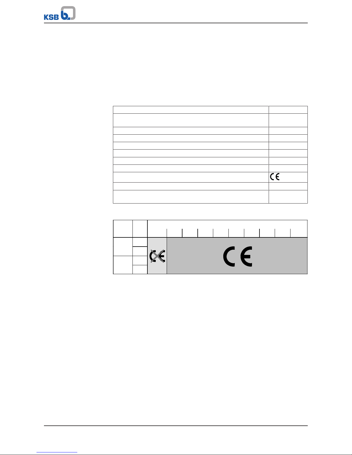
CE marking PED
Identification number of the notified body 0036
Customer's marking e.g. plant/
system No., etc.
The CE marking on the valve indicates that it is in conformity with the European
Pressure Equipment Directive 2014/68/EU.
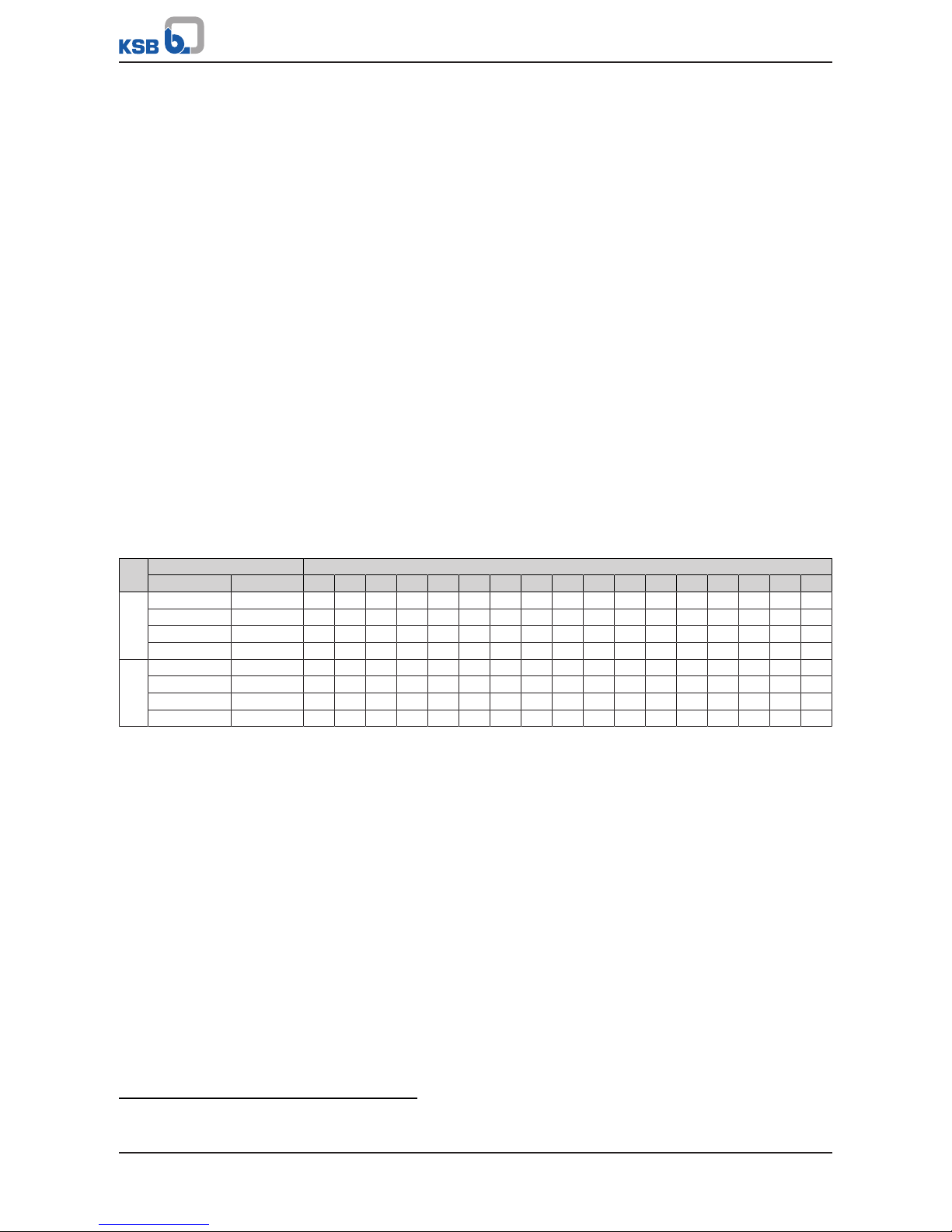
Fluids in Groups 1 and 2
Class PN DN
≤25 32 40 50 65 80 100 125 150 ≥200
10
16
25
≥
≥40
150
300
Fluid groups In accordance with Article13 Para.1 of Pressure Equipment Directive 2014/68/EU,
Group 1 comprises all fluids posing physical or health hazards, e.g. fluids defined as
▪ Explosive
▪ Extremely flammable
▪ Highly flammable
▪ Flammable: The maximum allowable temperature is above flashpoint
▪ Very toxic
▪ Toxic
▪ Oxidising
Group 2 comprises all other fluids not referred to in Group 1.
4.3 Gate Valves
4.3.1 Function of gate valves with bolted bonnet
The valve consists of the pressure-retaining parts, i.e. body 100 and yoke 166, and the
functional unit.
Body 100 and yoke 166 are connected by studs 902.1 or grub screws 904 and nuts
920.1, and the joint is sealed off by joint ring 411.1.
4 Valve Description
15 of 68
The functional unit consists mainly of wedge holder 367, flexibly mounted wedge
discs 360 and stem 200. The actuating element is either a handwheel 961 or an
actuator.
The seating faces of body 100 and wedge discs 360 are hard-faced. Gland packing
461, which seals off stem 200, is tightened via gland follower 452 by means of studs
902.3 or hinged bolts and nuts 920.2.
4.3.2 Function of gate valves with pressure seal bonnet
Gate valves with wedge discs 360 consist of body 100 with welded stellited seat rings
515, wedge discs 360 with stellited seating faces, bonnet 139 with gland packing 461
and yoke 166 with the actuating element.
Shut-off is performed by two wedge discs 360 pressed against seat rings 515; they are
flexibly mounted in wedge holder 367 and supported by replaceable thrust inserts
553 via pins 563.
Wedge holder 367 is screwed onto stem 200. A retainer prevents wedge discs 360
from twisting in wedge holder 367. To prevent twisting of the obturator
components, the wedge holder is guided in the body by lateral guide ribs 752. The
valve is equipped with a pressure seal bonnet.
The pressure inside body 100 presses bonnet 139 against joint ring 411.1, which is
supported by compression ring 501. The studs 902.2 and hexagon nuts 920.6, which
are supported by thrust plate 414 ensure that bonnet 139 is held in position against
joint ring 411.1, even if there is no pressure inside body 100.
For fitting a body pressure relief valve (ðSection4.4.1,Page29) (see type series
booklet 7300.1) a 22/14x74mm connection branch 131.2 is welded to body 100. The
connection branch is closed upon delivery.
Body pressure relief valves, if ordered, are supplied unassembled, i.e. attached loosely
to the gate valve.
Instead of fitting a body pressure relief valve, the operator may also provide a means
of pressure balancing between the body's middle section and the gate valve's
pressurised connection branch, e.g.:
▪ a pressure balancing hole in the seat ring or
▪ an external balancing line.
In this case the gate valve can be used for one flow direction only.
If gate valves and swing check valves in pressure seal design (bonnet 139) are fitted in
close proximity to one another, meaning that the trapped liquid could heat up if the
valves are closed, the operator must fit a body pressure relief valve.
Gland packing 461, which seals off stem 200, is tightened via gland follower 452 by
means of studs 902.3 and nuts 920.1. Stem 200 is moved in axial direction by the
rotating threaded bush 544, which is fitted with cylindrical roller bearings 323. Stem
200 lifts off wedge discs 360 or presses them against seat rings 515.
Threaded bush 544 is positioned in the yoke head by intermediate flange 729 and
hexagon socket head cap screws 914.1. Handwheel 961 sits on threaded bush 544, to
which it is joined via key 940. It is secured by circlip 932.
The stop nut 920.3 fitted on stem 200 serves as a travel stop in closing direction. It
prevents jamming of the wedge assembly in the seat and is secured by parallel pin
562.3.
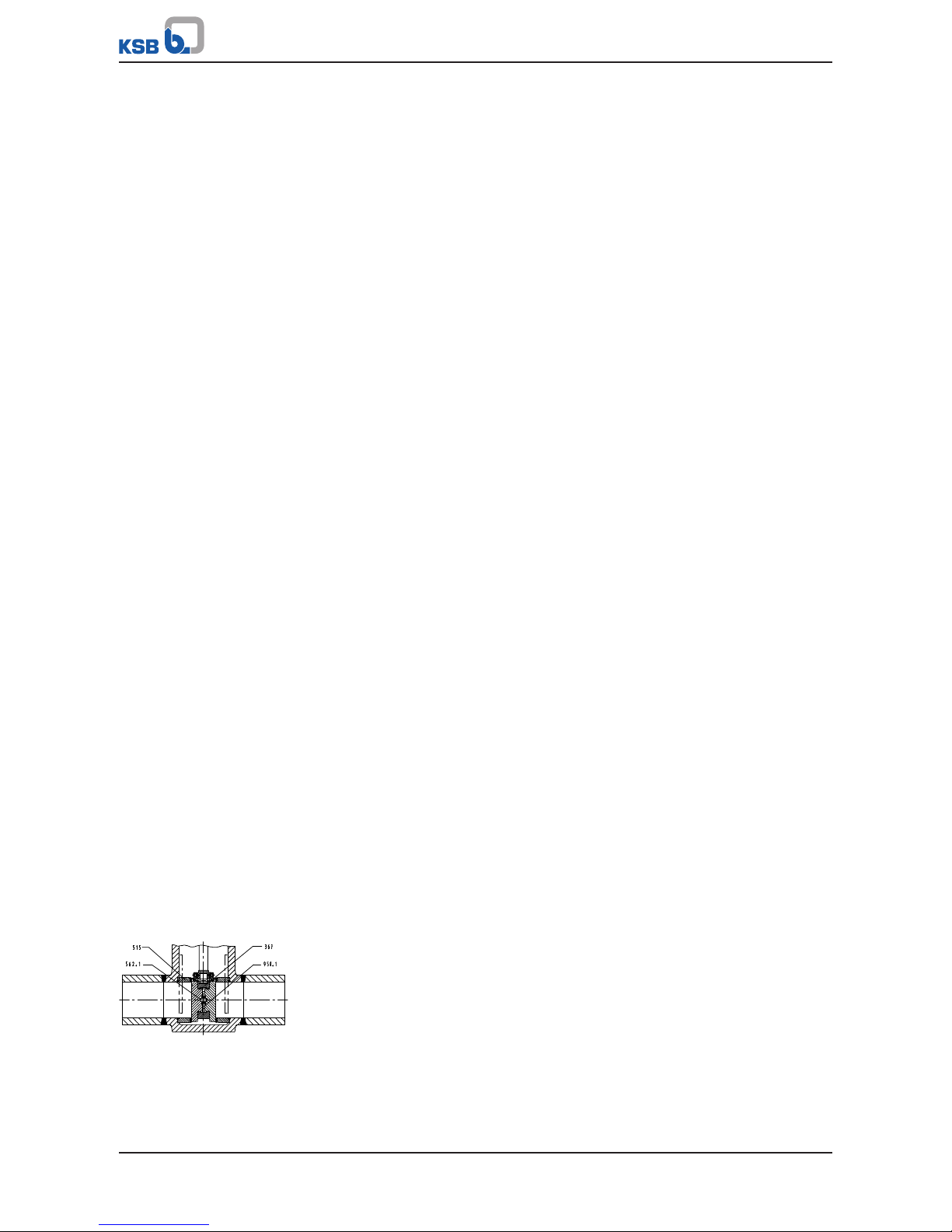
Fig.2: Parallel discs
Unlike wedge gate valve designs, slide gate valves feature two parallel discs 368,
which are flexibly mounted in disc holder 367. The discs are supported by replaceable
disc springs 950.1 via parallel pins 562.1, which press them against seat rings 515.
4 Valve Description
16 of 68
4.3.3 Gate Valves to DIN/EN with Bolted Bonnet
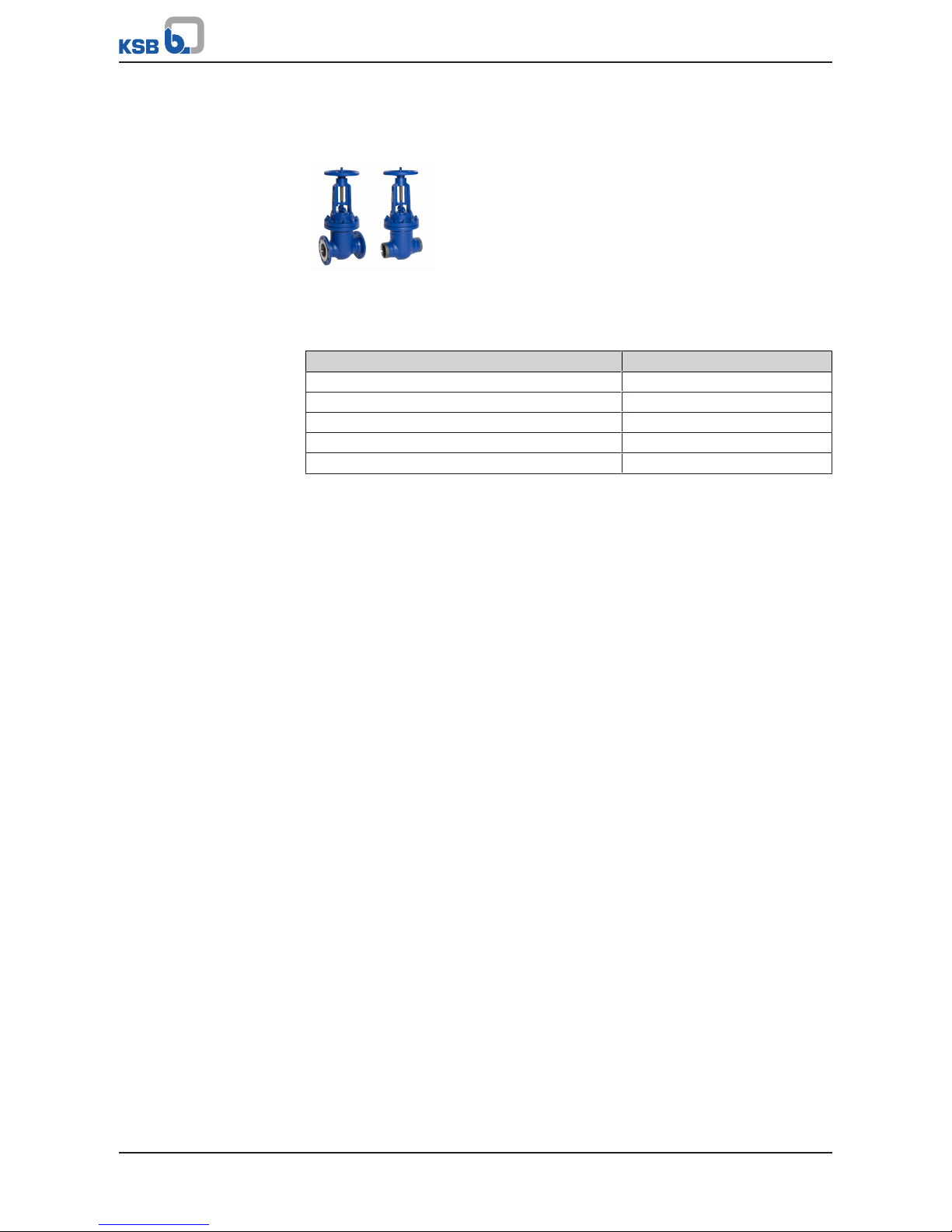
4.3.3.1 STAAL 40 AKD/AKDS
4.3.3.1.1 Operating data
Table5: Operating properties
Characteristic Value
Nominal pressure PN 10 - 40
Nominal size DN 50 - 600
Max. permissible pressure [bar] 40
Min. permissible temperature [°C] ≥-10
Max. permissible temperature [°C] ≤+450
Selection as per pressure/temperature ratings (ðSection4.3.3.1.4,Page17)
4.3.3.1.2 Fluids handled
▪ Water
▪ Steam
▪ Other non-aggressive fluids such as gas or oil on request.
4.3.3.1.3 Design details
Design
▪ Body of forged or welded steel construction
▪ Bolted bonnet
▪ Non-rotating stem with external screw
▪ Split wedge
▪ Standard position indicator ≤ DN200
▪ Yoke head suitable for mounting electric actuators (DINISO5210)
▪ The valves satisfy the safety requirements of AnnexI of the European Pressure
Equipment Directive2014/68/EU (PED) for fluids in Groups1and2.
▪ The valves do not have a potential internal source of ignition and can be used in
potentially explosive atmospheres, GroupII, category2 (zones1+21) and
category3 (zones2+22) to ATEX2014/34/EU.
Variants
▪ Stem protecting tube
▪ Stem protecting tube with position indicator (≥ DN250)
▪ Stem protecting tube with position switch (≥ DN250)
▪ Position switch(es) mounted on yoke (≤DN200)
▪ Bypass
▪ Drain branch
▪ Barrier water connection
▪ Electric actuators

4 Valve Description
17 of 68
▪ Actuator installation kit
▪ Seat/disc interface made of wear-resistant and corrosion-proof Stellite
▪ Stem made of 1.4122
▪ TA-Luft-compliant model (with or without spring loading) for applications to
VDI2440 at temperatures ≤ 250°C and > 250°C (400°C maximum)
▪ Other flange designs or butt weld end designs
▪ Inspections to technical codes such as TRD/TRB/AD2000 – German Steam Boiler /
Pressure Vessel Regulations – or to customer specification
▪ ≥ DN 700 on request
4.3.3.1.4 Pressure/temperature ratings
Table6: Permissible operating pressure [bar] (to EN 1092-1)
4)
PN Material [°C]
RT
5)
100 150 200 250 300 350 400 450
10 P250GH / P265GH 10,0 9,2 8,8 8,3 7,6 6,9 6,4 5,9 3,2
16 16,0 14,8 14,0 13,3 12,1 11,0 10,2 9,5 5,2
25 25,0 23,2 22,0 20,8 19,0 17,2 16,0 14,8 8,2
40 40,0 37,1 35,2 33,3 30,4 27,6 25,7 23,8 13,1
4) Operating pressures in accordance with DIN 2401 are also permissible.
5) RT: room temperature (-10°C to +50°C)
4 Valve Description
18 of 68
4.3.3.1.5 Materials
PN 10 - 40
DN 50 - 200
PN 40
DN 250 - 600
AKD AKDS AKD AKDS
Table7: Parts list
Part No. Description Material Material number Note
100 Body P 250 GH 1.0460 -
P265GH 1.0425 ≥ DN 250
131.1 Connection branch P 235 GH 1.0345 P265GH 1.0425 ≥ DN 500
165 Bonnet P 250GH 1.0460 166 Yoke GP 240 GH+N 1.0619+N -
P265GH 1.0425 ≥ DN 250
200
6)
Stem X 20 Cr 13+QT800 1.4021+QT800 -
323
6)
Thrust bearing Steel - -
360
6)
Wedge discs GP 240 GH+N 1.0619+N -
P265GH 1.0425 ≥ DN 250
367
6)
Disc/wedge holder P 250 GH 1.0460 -
P265GH 1.0425 ≥ DN 250
Seat/disc
interface
Body X20CrMo171 1.4115 17% chrome steel
Wedge discs X8CrTi18 1.4502
411
6)
Joint ring CrNi steel/graphite - 452 Gland follower P250GH/P265GH 1.0460 / 1.0425 461
6)
Gland packing Pure graphite - 544
6)
Threaded bush 46S20+C 1.0727+C DN 50-200, nitrocarburised
11SMn30+C 1.0715+C ≥ DN 250, nitrided
579 Stop S235JR - 723 Flange P 250 GH 1.0460 902 Stud 25CrMo4 1.7218 920 Hexagon nut C35E 1.1181 961 Handwheel EN-GJL-250 5.1301 DN 50-200
Steel - ≥ DN 250
6) Recommended spare parts
4 Valve Description
19 of 68
4.3.3.2 STAAL 100 AKD/AKDS
4.3.3.2.1 Operating data
Table8: Operating properties
Characteristic Value
Nominal pressure PN 63 - 100
Nominal size DN 50 - 500
Max. permissible pressure [bar] 100
Min. permissible temperature [°C] ≥-10
Max. permissible temperature [°C] ≤+530
Selection as per pressure/temperature ratings (ðSection4.3.3.2.4,Page20)
4.3.3.2.2 Fluids handled
▪ Water
▪ Steam
▪ Other non-aggressive fluids such as gas or oil on request.
4.3.3.2.3 Design details
Design
▪ Body of forged or welded steel construction
▪ Bolted bonnet
▪ Non-rotating stem with external screw
▪ Split wedge
▪ Yoke head suitable for mounting electric and pneumatic actuators (DINISO5210)
▪ The valves satisfy the safety requirements of Annex I of the European Pressure
Equipment Directive 2014/68/EU(PED) for fluids in Groups1and2.
▪ The valves do not have a potential internal source of ignition and can be used in
potentially explosive atmospheres, GroupII, category2 (zones1+21) and
category3 (zones2+22) to ATEX2014/34/EU.
4 Valve Description
20 of 68
Variants
▪ Stem protecting tube
▪ Stem protecting tube with position indicator
▪ Limit switch(es)
▪ Bypass
▪ Drain branch
▪ Hard-faced back seat
▪ Threaded bush free from non-ferrous metals
▪ Electric actuators
▪ Pneumatic actuators
▪ Spur gear
▪ Bevel gear
▪ Actuating bush for remote actuation
▪ Other flange designs or butt weld end designs
▪ Inspections to technical codes such as TRD/TRB/AD2000 – German Steam Boiler /
Pressure Vessel Regulations – or to customer specification
▪ Die-forged model for DN300/250 on request.
▪ DN 500 and above on request
4.3.3.2.4 Pressure/temperature ratings
Table9: Permissible operating pressure [bar] (to EN 1092-1)
7)
PN Material [°C]
Designation Number RT8)100 150 200 250 300 350 400 450 460 470 480 490 500 510 520 530
63 P250GH 1.0460 63,0 58,5 55,5 52,5 48,0 43,5 40,5 37,5 20,7 - - - - - - - -
P265GH 1.0425 63,0 58,5 55,5 52,5 48,0 43,5 40,5 37,5 20,7 - - - - - - - 16Mo3 1.5415 63,0 63,0 63,0 63,0 61,5 54,0 51,0 47,1 43,5 40,3 37,2 34,1 31,0 27,9 - - 13CrMo4-5 1.7335 63,0 63,0 63,0 63,0 63,0 63,0 60,0 56,7 53,1 50,5 47,9 45,4 42,8 41,1 34,8 28,2 23,4
100 P250GH 1.0460 100,0 92,8 88,0 83,3 76,1 69,0 64,2 59,5 32,8 - - - - - - - -
P265GH 1.0425 100,0 92,8 88,0 83,3 76,1 69,0 64,2 59,5 32,8 - - - - - - - 16Mo3 1.5415 100,0 100,0 100,0 100,0 100,0 97,6 80,9 74,7 69,0 64,0 59,1 54,2 49,2 44,2 - - 13CrMo4-5 1.7335 100,0 100,0 100,0 100,0 100,0 100,0 95,2 90,0 84,2 80,2 76,1 72,0 68,0 65,2 55,2 44,7 37,1
7) Operating pressures in accordance with DIN 2401 are also permissible.
8) RT: room temperature (-10°C to +50°C)
4 Valve Description
21 of 68
4.3.3.2.5 Materials
DN 50/50-250/250 DN 300/300-500/500
AKD AKD
AKDS AKDS
Table10: Parts list DN 50/50-250/250
Part No. Description Temperature
[°C]
Material Material number Note
100 Body ≤ 450 P 250 GH 1.0460 Body die-forged and
welded
≤ 530 13CrMo4-5 1.7335
723 Flange ≤ 450 P 250 GH 1.0460 -
≤ 530 13CrMo4-5 1.7335
131.1 Connection
branch
≤ 450 P 250 GH 1.0460 Material can be matched to
pipeline material
≤ 530 13CrMo4-5 1.7335
360
9)
Wedge discs ≤ 450 P 250 GH 1.0460 -
≤ 530 13CrMo4-5 1.7335
367
9)
Disc/wedge holder ≤ 450 P 250 GH 1.0460 -
≤ 530 13CrMo4-5 1.7335
166 Yoke ≤ 450 P 250 GH 1.0460 -
9) Recommended spare parts
 Loading...