

KSB Sewabloc Series Operating Manual

Dry-installed Volute Casing Pump
Sewabloc
50 / 60 Hz
DIN / IEC motors
Installation/Operating Manual
Mat. No.: 01104323

Legal information/Copyright
Installation/Operating Manual Sewabloc
Original operating manual
All rights reserved. The contents provided herein must neither be distributed, copied, reproduced,
edited or processed for any other purpose, nor otherwise transmitted, published or made available to a
third party without the manufacturer's express written consent.
Subject to technical modification without prior notice.
© KSB SE & Co. KGaA, Frankenthal 24/08/2018

Contents
3 of 60
Sewabloc
Contents
Glossary .................................................................................................................................................. 5
1 General.................................................................................................................................................... 6
1.1 Principles ...........................................................................................................................................................6
1.2 Installation of partly completed machinery....................................................................................................6
1.3 Target group.....................................................................................................................................................6
1.4 Other applicable documents............................................................................................................................6
1.5 Symbols .............................................................................................................................................................6
2 Safety...................................................................................................................................................... 8
2.1 Key to safety symbols/markings.......................................................................................................................8
2.2 General..............................................................................................................................................................8
2.3 Intended use .....................................................................................................................................................9
2.4 Personnel qualification and training...............................................................................................................9
2.5 Consequences and risks caused by non-compliance with this manual .......................................................10
2.6 Safety awareness ............................................................................................................................................10
2.7 Safety information for the operator/user.....................................................................................................10
2.8 Safety information for maintenance, inspection and installation ..............................................................10
2.9 Unauthorised modes of operation................................................................................................................11
2.10 Explosion protection ......................................................................................................................................11
2.10.1 Marking ..............................................................................................................................................11
3 Transport/Temporary Storage/Disposal............................................................................................. 12
3.1 Checking the condition upon delivery..........................................................................................................12
3.2 Transport.........................................................................................................................................................12
3.3 Storage/preservation......................................................................................................................................13
3.4 Return to supplier...........................................................................................................................................13
3.5 Disposal ...........................................................................................................................................................14
4 Description of the Pump (Set)............................................................................................................. 15
4.1 General description ........................................................................................................................................15
4.2 Designation.....................................................................................................................................................16
4.3 Name plate......................................................................................................................................................16
4.4 Design details..................................................................................................................................................16
4.5 Configuration and function...........................................................................................................................17
4.6 Noise characteristics .......................................................................................................................................17
4.7 Scope of supply...............................................................................................................................................18
4.8 Dimensions and weights ................................................................................................................................18
5 Installation at Site................................................................................................................................ 19
5.1 Safety regulations...........................................................................................................................................19
5.2 Checks to be carried out prior to installation...............................................................................................19
5.3 Setting up the pump set ................................................................................................................................19
5.4 Piping ..............................................................................................................................................................21
5.4.1 Connecting the piping.......................................................................................................................21
5.4.2 Permissible forces and moments at the pump nozzles....................................................................22
5.4.3 Vacuum balance line..........................................................................................................................23
5.5 Auxiliary connections .....................................................................................................................................24
5.6 Checking the lubricants..................................................................................................................................24
5.7 Electrical connection ......................................................................................................................................25
5.8 Checking the direction of rotation................................................................................................................26
5.9 Priming and venting the pump .....................................................................................................................26
6 Commissioning/Start-up/Shutdown................................................................................................... 27
6.1 Commissioning/Start-up.................................................................................................................................27
6.1.1 Prerequisites for commissioning/start-up .........................................................................................27
6.1.2 Start-up...............................................................................................................................................27

Contents
4 of 60
Sewabloc
6.1.3 Shutdown ...........................................................................................................................................28
6.2 Operating limits..............................................................................................................................................28
6.2.1 Maximum operating pressure ...........................................................................................................29
6.2.2 Frequency of starts.............................................................................................................................30
6.2.3 Fluid handled .....................................................................................................................................30
6.3 Shutdown/storage/preservation ....................................................................................................................30
6.4 Returning to service .......................................................................................................................................31
7 Servicing/Maintenance........................................................................................................................ 32
7.1 Safety regulations...........................................................................................................................................32
7.2 Servicing/Inspection........................................................................................................................................33
7.2.1 Supervision of operation ...................................................................................................................33
7.2.2 Inspection work..................................................................................................................................34
7.2.3 Lubrication and lubricant change.....................................................................................................35
7.3 Drainage/cleaning ..........................................................................................................................................38
7.4 Dismantling the pump set..............................................................................................................................38
7.4.1 General information/Safety regulations...........................................................................................38
7.4.2 Preparations for dismantling ............................................................................................................39
7.4.3 Separating the pump from the piping .............................................................................................39
7.4.4 Removing the pump set ....................................................................................................................40
7.4.5 Removing the motor..........................................................................................................................40
7.4.6 Removing the impeller ......................................................................................................................40
7.4.7 Dismantling the mechanical seal ......................................................................................................42
7.4.8 Removing shaft and rolling element bearing ..................................................................................43
7.4.9 Removing the wear plate (for D type impellers only) .....................................................................44
7.5 Reassembling the pump set...........................................................................................................................44
7.5.1 General information/Safety regulations...........................................................................................44
7.5.2 Installing the shaft and rolling element bearings ...........................................................................45
7.5.3 Installing the mechanical seal ...........................................................................................................45
7.5.4 Fitting the impeller ............................................................................................................................48
7.5.5 Installing the back pull-out unit .......................................................................................................49
7.5.6 Leak test .............................................................................................................................................50
7.6 Tightening torques.........................................................................................................................................50
7.7 Spare parts stock.............................................................................................................................................51
7.7.1 Ordering spare parts..........................................................................................................................51
7.7.2 Recommended spare parts stock for 2 years' operation to DIN24296 ..........................................51
8 Trouble-shooting.................................................................................................................................. 52
9 Related Documents.............................................................................................................................. 54
9.1 General assembly drawing – Sewabloc .........................................................................................................54
9.2 Exploded view of a Sewabloc ........................................................................................................................55
10 EU Declaration of Conformity............................................................................................................. 56
11 Certificate of Decontamination........................................................................................................... 57
Index ..................................................................................................................................................... 58

Glossary
5 of 60
Sewabloc
Glossary
Certificate of decontamination
A certificate of decontamination is enclosed by the
customer when returning the product to the
manufacturer to certify that the product has been
properly drained to eliminate any environmental
and health hazards arising from components in
contact with the fluid handled.
Discharge line
The pipeline which is connected to the discharge
nozzle
Hydraulic system
The part of the pump in which the kinetic energy
is converted into pressure energy
Pump
Machine without drive, additional components or
accessories
Pump set
Complete pump set consisting of pump, drive,
additional components and accessories
Suction lift line/suction head line
The pipeline which is connected to the suction
nozzle
1 General
6 of 60
Sewabloc
1 General
1.1 Principles
This operating manual is supplied as an integral part of the type series and variants
indicated on the front cover.
The manual describes the proper and safe use of this equipment in all phases of
operation.
The name plate indicates the type series and size, the main operating data, the order
number and the order item number. The order number and order item number
clearly identify the pump set and serve as identification for all further business
processes.
In the event of damage, immediately contact your nearest KSB Service centre to
maintain the right to claim under warranty.
1.2 Installation of partly completed machinery
To install partly completed machinery supplied by KSB refer to the sub-sections under
Servicing/Maintenance. (ðSection7.5.5,Page49)
1.3 Target group
This operating manual is aimed at the target group of trained and qualified specialist
technical personnel. (ðSection2.4,Page9)
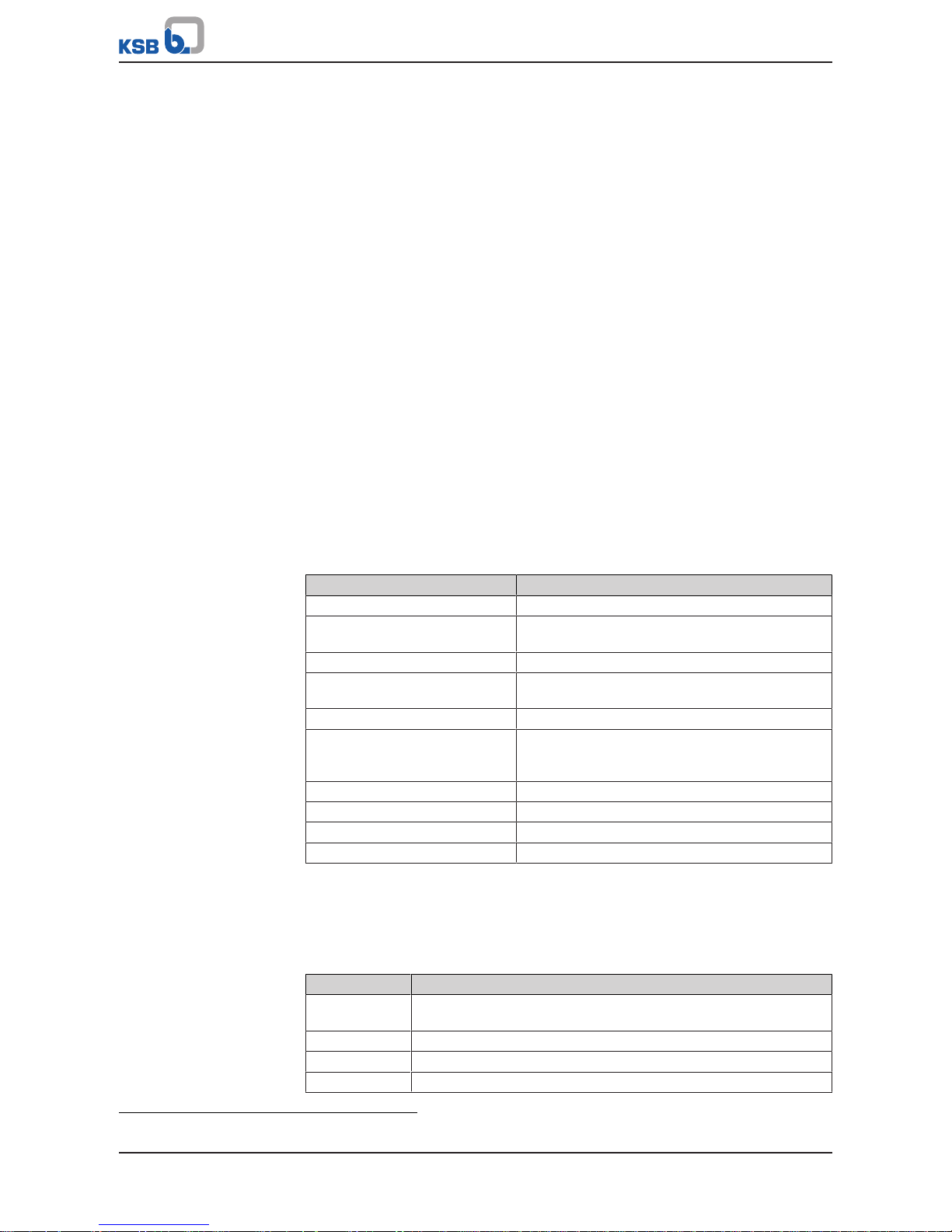
1.4 Other applicable documents
Table1: Overview of other applicable documents
Document Contents
Data sheet Description of the technical data of the pump (set)
General arrangement drawing/
outline drawing
Description of mating and installation dimensions
for the pump (set), weights
Drawing of auxiliary connections Description of auxiliary connections
Hydraulic characteristic curve Characteristic curves showing head, NPSH
required, efficiency and power input
General assembly drawing
1)
Sectional drawing of the pump
Sub-supplier product literature1)Operating manuals and other product literature
describing accessories and integrated machinery
components
Spare parts lists
1)
Description of spare parts
Piping layout
1)
Description of auxiliary piping
List of components
1)
Description of all pump components
Drawing for assembly
1)
Sectional drawing of the installed shaft seal
For accessories and/or integrated machinery components observe the relevant
manufacturer's product literature.
1.5 Symbols
Table2: Symbols used in this manual
Symbol Description
✓ Conditions which need to be fulfilled before proceeding with the
step-by-step instructions
⊳ Safety instructions
⇨
Result of an action
⇨ Cross-references
1) If agreed upon in scope of supply

1 General
7 of 60
Sewabloc
Symbol Description
1.
2.
Step-by-step instructions
Note
Recommendations and important information on how to handle
the product
2 Safety
8 of 60
Sewabloc
2 Safety
!
DANGER
All the information contained in this section refers to hazardous situations.
In addition to the present general safety information the action-related safety
information given in the other sections must be observed.
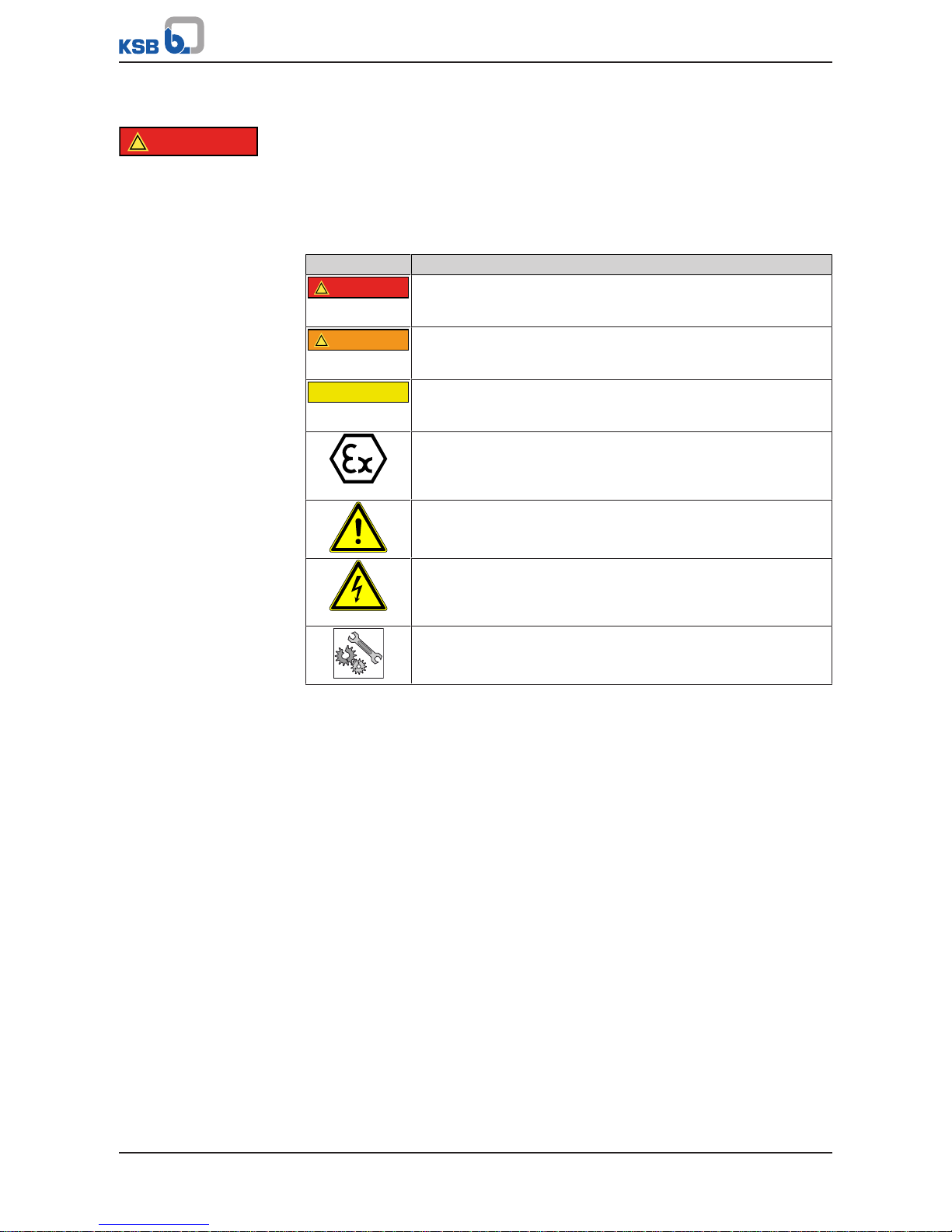
2.1 Key to safety symbols/markings
Table3: Definition of safety symbols/markings
Symbol Description
!
DANGER
DANGER
This signal word indicates a high-risk hazard which, if not avoided,
will result in death or serious injury.
!
WARNING
WARNING
This signal word indicates a medium-risk hazard which, if not
avoided, could result in death or serious injury.
CAUTION
CAUTION
This signal word indicates a hazard which, if not avoided, could
result in damage to the machine and its functions.
Explosion protection
This symbol identifies information about avoiding explosions in
potentially explosive atmospheres in accordance with EU Directive
2014/34/EU (ATEX).
General hazard
In conjunction with one of the signal words this symbol indicates a
hazard which will or could result in death or serious injury.
Electrical hazard
In conjunction with one of the signal words this symbol indicates a
hazard involving electrical voltage and identifies information about
protection against electrical voltage.
Machine damage
In conjunction with the signal word CAUTION this symbol indicates
a hazard for the machine and its functions.
2.2 General
This operating manual contains general installation, operating and maintenance
instructions that must be observed to ensure safe operation of the system and
prevent personal injury and damage to property.
The safety information in all sections of this manual must be complied with.
The operating manual must be read and understood by the responsible specialist
personnel/operators prior to installation and commissioning.
The contents of this operating manual must be available to the specialist personnel
at the site at all times.
Information attached directly to the product must always be complied with and kept
in a perfectly legible condition at all times. This applies to, for example:
▪ Arrow indicating the direction of rotation
▪ Markings for connections
▪ Name plate
The operator is responsible for ensuring compliance with all local regulations not
taken into account in this operating manual.
2 Safety
9 of 60
Sewabloc
2.3 Intended use
▪ The pump set must only be operated within the operating limits described in the
other applicable documents.
▪ Only operate pump sets which are in perfect technical condition.
▪ Do not operate partially assembled pump sets.
▪ Only use the pump to handle the fluids described in the data sheet or product
literature of the pump model.
▪ Never operate the system without the fluid to be handled.
▪ Observe the limits for continuous duty specified in the data sheet or product
literature (Q
min
and Q
max
) (to prevent damage such as shaft fracture, bearing
failure, mechanical seal damage, etc).
▪ When untreated waste water is handled, the duty points in continuous operation
lie within 0.7 to 1.2×Q
opt
to minimise the risk of clogging/hardening.
▪ Avoid duty points for continuous operation at very low speeds and small flow
rates (<0.7×Q
opt
).
▪ Observe the minimum flow rate and maximum flow rate indicated in the data
sheet or product literature (to prevent overheating, mechanical seal damage,
cavitation damage, bearing damage, etc).
▪ Do not throttle the flow rate on the suction side of the system (prevention of
cavitation damage).
▪ Consult the manufacturer about any use or mode of operation not described in
the data sheet or product literature.
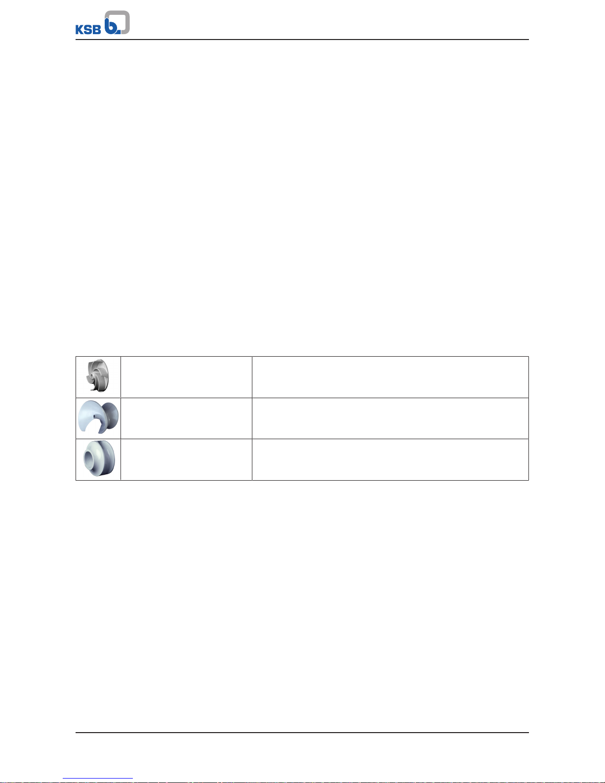
▪ Only use the respective impeller types in combination with the fluids described
below.
Free-flow impeller
(impeller type F/F-max)
Suitable for the following fluids:
fluids containing solids and stringy material as well as fluids with
entrapped air or entrapped gas
Open, diagonal single-channel
impeller
(impeller type D)
Suitable for the following fluids:
fluids containing solid substances and long fibres
Closed multi-channel impeller
(impeller type K/K-max)
Suitable for the following fluids:
contaminated, solids-laden, non-gaseous fluids without stringy
material
Prevention of foreseeable misuse
▪ Observe the minimum flow velocities required to fully open the swing check
valves to prevent the reduction of pressure and risk of clogging.
(Contact the manufacturer for the required minimum flow velocities/loss
coefficients.)
▪ Never exceed the permissible application and operating limits specified in the
data sheet or product literature regarding pressure, temperature, etc.
▪ Observe all safety information and instructions in this manual.
2.4 Personnel qualification and training
All personnel involved must be fully qualified to transport, install, operate, maintain
and inspect the machinery this manual refers to.
The responsibilities, competence and supervision of all personnel involved in
transport, installation, operation, maintenance and inspection must be clearly
defined by the operator.
Deficits in knowledge must be rectified by means of training and instruction
provided by sufficiently trained specialist personnel. If required, the operator can
commission the manufacturer/supplier to train the personnel.

2 Safety
10 of 60
Sewabloc
Training on the pump (set) must always be supervised by technical specialist
personnel.
2.5 Consequences and risks caused by non-compliance with this manual
▪ Non-compliance with these operating instructions will lead to forfeiture of
warranty cover and of any and all rights to claims for damages.
▪ Non-compliance can, for example, have the following consequences:
– Hazards to persons due to electrical, thermal, mechanical and chemical
effects and explosions
– Failure of important product functions
– Failure of prescribed maintenance and servicing practices
– Hazard to the environment due to leakage of hazardous substances
2.6 Safety awareness
In addition to the safety information contained in this manual and the intended use,
the following safety regulations shall be complied with:
▪ Accident prevention, health regulations and safety regulations
▪ Explosion protection regulations
▪ Safety regulations for handling hazardous substances
▪ Applicable standards, directives and laws
2.7 Safety information for the operator/user
▪ Fit protective equipment (e.g. contact guards) supplied by the operator for hot,
cold or moving parts, and check that the equipment functions properly.
▪ Do not remove any protective equipment (e.g. contact guards) during operation.
▪ Provide the personnel with protective equipment and make sure it is used.
▪ Contain leakages (e.g. at the shaft seal) of hazardous fluids handled (e.g.
explosive, toxic, hot) so as to avoid any danger to persons and the environment.
Adhere to all relevant laws.
▪ Eliminate all electrical hazards. (In this respect refer to the applicable national
safety regulations and/or regulations issued by the local energy supply
companies.)
▪ If shutting down the pump does not increase potential risk, fit an emergency-
stop control device in the immediate vicinity of the pump (set) during pump set
installation.
2.8 Safety information for maintenance, inspection and installation
▪ Modifications or alterations of the pump (set) are only permitted with the
manufacturer's prior consent.
▪ Use only original spare parts or parts/components authorised by the
manufacturer. The use of other parts/components can invalidate any liability of
the manufacturer for resulting damage.
▪ The operator ensures that maintenance, inspection and installation is performed
by authorised, qualified specialist personnel who are thoroughly familiar with
the manual.
▪ Only carry out work on the pump (set) during standstill of the pump.
▪ Only perform work on the pump set when it has been disconnected from the
power supply (de-energised).
▪ The pump (set) must have cooled down to ambient temperature.
▪ Pump pressure must have been released and the pump must have been drained.
2 Safety
11 of 60
Sewabloc
▪ When taking the pump set out of service always adhere to the procedure
described in the manual.
▪ Decontaminate pumps which handle fluids posing a health hazard.
(ðSection7.3,Page38)
▪ As soon as the work has been completed, re-install and re-activate any safety-
relevant devices and protective devices. Before returning the product to service,
observe all instructions on commissioning. (ðSection6.1,Page27)
2.9 Unauthorised modes of operation
Never operate the pump (set) outside the limits stated in the data sheet and in this
manual.
The warranty relating to the operating reliability and safety of the supplied pump
(set) is only valid if the equipment is used in accordance with its intended use.
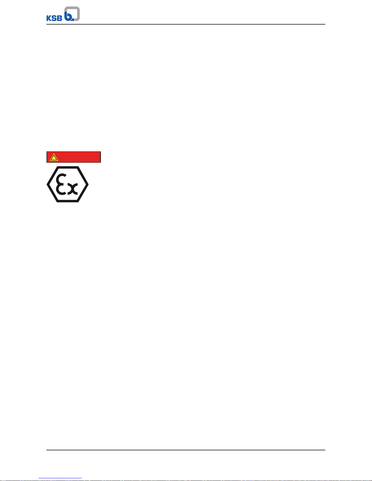
2.10 Explosion protection
!
DANGER
Always observe the information on explosion protection given in this section when
operating an explosion-proof pump set.
Sections of the manual marked by the symbol opposite apply to explosion-proof
pump sets also when temporarily operated outside of potentially explosive
atmospheres.
Only pumps/pump sets marked as explosion-proof and identified as such in the data
sheet may be used in potentially explosive atmospheres.
Special conditions apply to the operation of an explosion-proof pump set to
EUDirective 2014/34/EU (ATEX).
Especially adhere to the sections in this manual marked with the symbol opposite.
The explosion-proof status of the pump set is only assured if the pump set is used in
accordance with its intended use.
Never operate the pump set outside the limits stated in the data sheet and on the
name plate.
Prevent impermissible modes of operation.
2.10.1 Marking
Pump The marking on the pump refers to the pump part only.
Example of such marking:
II 2 G c IIB TX (EN 13463-1) or II 2 G Ex h IIB T5 -T1 Gb (ISO 80079-36)
Refer to the individual Temperature Limits table for the temperatures permitted for
the individual pump variants.
The pump complies with the requirements of type of protection constructional safety
"c" to ISO80079-37.
Shaft coupling An EC manufacturer's declaration is required for the shaft coupling; the shaft
coupling must be marked accordingly.
Motor The motor must be considered separately.

3 Transport/Temporary Storage/Disposal
12 of 60
Sewabloc
3 Transport/Temporary Storage/Disposal
3.1 Checking the condition upon delivery
1. On transfer of goods, check each packaging unit for damage.
2. In the event of in-transit damage, assess the exact damage, document it and
notify KSB or the supplying dealer and the insurer about the damage in writing
immediately.
3.2 Transport
DANGER
The pump (set) could slip out of the suspension arrangement
Danger to life from falling parts!
▷ Always transport the pump (set) in the specified position.
▷ Observe the applicable local accident prevention regulations.
▷ Give due attention to the weight data, centre of gravity and fastening points.
▷ Use suitable, permitted lifting accessories, e.g. self-tightening lifting tongs.
WARNING
Uncontrolled lifting of the pump (set) or drive
Risk of injury!
▷ Maintain adequate safety distance during lifting operations (load may swing
when being lifted).
WARNING
Placing the pump set on unsecured and uneven surfaces
Personal injury and damage to property!
▷ Only place the pump set on a surface of sufficient load-carrying capacity.
▷ Use appropriate means to secure the pump set against tilting or tipping over.
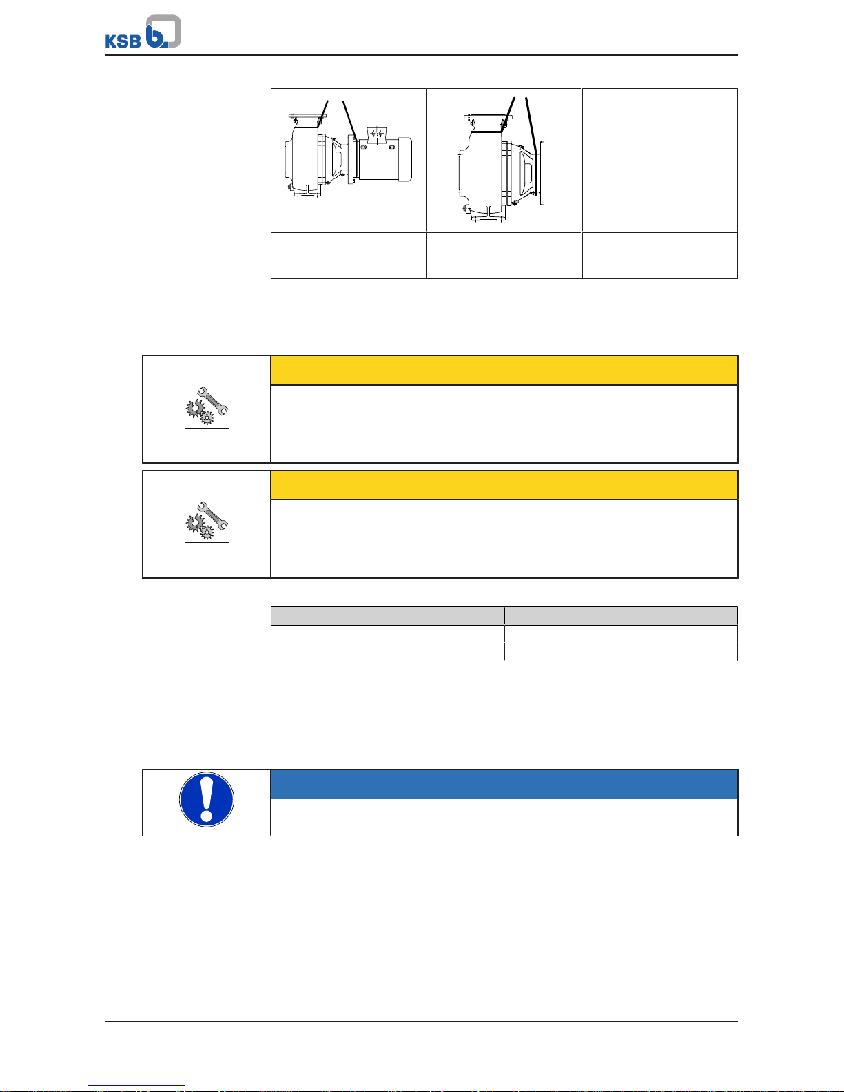
To transport the pump/pump set suspend it from the lifting tackle as shown.
Table4: Transport options
Vertical transport
Close-coupled pump V
Vertical transport
Close-coupled pump VF
Vertical transport
Close-coupled pump
without motor
3 Transport/Temporary Storage/Disposal
13 of 60
Sewabloc
Horizontal transport
Close-coupled pump
Horizontal transport
Close-coupled pump
without motor
3.3 Storage/preservation
If commissioning is to take place some time after delivery, we recommend that the
following measures be taken:
CAUTION
Damage during storage due to humidity, dirt or vermin
Corrosion/contamination of the pump (set)!
▷ For outdoor storage cover the pump (set) or the packaged pump (set) and
accessories with waterproof material.
CAUTION
Wet, contaminated or damaged openings and connections
Leakage or damage to the pump!
▷ Clean and cover pump openings and connections as required prior to putting
the pump into storage.
Table5: Ambient conditions for storage
Ambient condition Value
Relative humidity 5% to 85% (non-condensing)
Ambient temperature -20°C to +70°C
▪ Store the pump set in dry, vibration-free conditions and in its original packaging.
(ðSection6.3,Page30)
1. Spray-coat the inside wall of the pump casing and, in particular, the impeller
clearance areas with a preservative.
2. Spray preservative through the suction nozzle and discharge nozzle.
It is advisable to then close the pump nozzles (e.g. with plastic caps or similar).
NOTE
Observe the manufacturer's instructions for application/removal of the preservative.
3.4 Return to supplier
1. Drain the pump as per operating instructions. (ðSection7.3,Page38)
2. Flush and clean the pump, particularly if it has been used for handling noxious,
explosive, hot or other hazardous fluids.
3 Transport/Temporary Storage/Disposal
14 of 60
Sewabloc
3. If the pump has handled fluids whose residues could lead to corrosion damage
in the presence of atmospheric humidity or could ignite upon contact with
oxygen also neutralise the pump and blow through with anhydrous inert gas to
ensure drying.
4. Always complete and enclose a certificate of decontamination when returning
the pump.
Indicate any safety measures and decontamination measures taken.
(ðSection11,Page57)
NOTE
If required, a blank certificate of decontamination can be downloaded from the
following web site: www.ksb.com/certificate_of_decontamination
3.5 Disposal
WARNING
Fluids handled, consumables and supplies which are hot and/or pose a health
hazard
Hazard to persons and the environment!
▷ Collect and properly dispose of flushing fluid and any fluid residues.
▷ Wear safety clothing and a protective mask if required.
▷ Observe all legal regulations on the disposal of fluids posing a health hazard.
1. Dismantle the pump (set).
Collect greases and other lubricants during dismantling.
2. Separate and sort the pump materials, e.g. by:
- Metals
- Plastics
- Electronic waste
- Greases and other lubricants
3. Dispose of materials in accordance with local regulations or in another
controlled manner.
4 Description of the Pump (Set)
15 of 60
Sewabloc
4 Description of the Pump (Set)
4.1 General description
Pump for handling untreated sewage and all types of waste water.
▪ Close-coupled pump with shaft seal
▪ Directly flanged standardised motor
▪ Direct drive electric motor
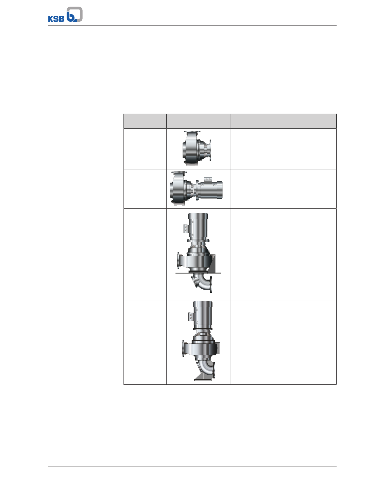
Table6: Installation types
Installation
type
Illustration Description
Close-coupled
pump without
motor
Pump can be supplied without motor,
horizontal installation
Figur Bloc Pump set with directly flanged motor
(construction type B5/V1), horizontal
installation
Figur Bloc V Pump set with directly flanged motor
(construction type B5/V1), vertical
installation, with soleplate and suction
elbow, underfloor installation
Close-coupled
pump VF
Pump set with directly flanged motor
(construction type B5/V1), vertical
installation, with suction duckfoot bend
4 Description of the Pump (Set)
16 of 60
Sewabloc
4.2 Designation
Example: Sewabloc F100-250GV
Table7: Designation key
Code Description
Sewabloc Type series
F Impeller type
100 Nominal discharge nozzle diameter [mm]
250 Nominal impeller diameter [mm]
G Material variant
V Installation type
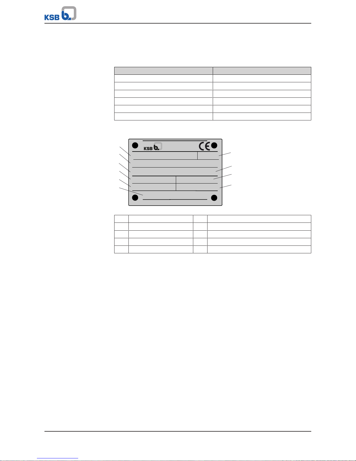
4.3 Name plate
SEWABLOC F 100 - 250
P-No. 9971402925 / 000200
Q 110,32 l/s H 4,87 m
n 949 1/min LD = 260
2016
Gew. 140 kg
SNr. 24 17 41
1
2
5
4
3
10
9
8
7
6
Johann-Klein-Straße 9
Deutschland
67227 Frankenthal
KSB SE & Co. KGaA
Fig.1: Name plate (example)
1 Series number 2 Identification of the pump set
3 Order number 4 Flow rate
5 Speed 6 Weight of the pump as close-coupled pump
7 Year of supply 8 Order item number
9 Head 10 Impeller diameter
4.4 Design details
Design
▪ Volute casing pump
▪ Close-coupled pump with shaft seal
▪ Various, application-oriented installation types (ðSection4.1,Page15)
Shaft seal
▪ Two bi-directional mechanical seals in tandem arrangement, with liquid reservoir
Impeller type
▪ Various application-oriented impeller types (ðSection2.3,Page9)
Bearings
▪ Grease-packed, zero-maintenance deep groove ball bearings (sealed for life) on
pump and drive end
4 Description of the Pump (Set)
17 of 60
Sewabloc
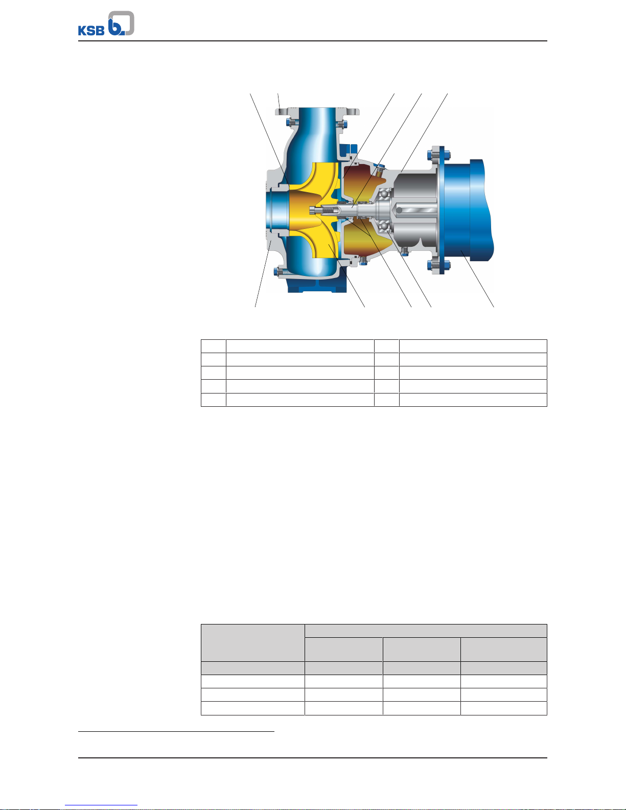
4.5 Configuration and function
2
3 4 5
10987
6
1
Fig.2: Sectional drawing Sewabloc with K impeller
1 Clearance gap 2 Discharge nozzle
3 Discharge cover 4 Shaft
5 Bearing bracket 6 Suction nozzle
7 Impeller 8 Shaft seal
9 Rolling element bearing 10 Motor
Design The hydraulic system and the motor are firmly connected and form a close-coupled
unit.
Impeller (7) and motor are arranged on a common shaft (4).
Function The fluid enters the pump via the suction nozzle (6) and is accelerated outward by
the rotating impeller (7). In the flow passage of the pump casing the kinetic energy
of the fluid is converted into pressure energy. The fluid is pumped to the discharge
nozzle (2), where it leaves the pump. The clearance gap (1) prevents any fluid from
flowing back from the casing to the suction nozzle. At the rear side of the impeller,
the shaft (4) enters the casing via the discharge cover (3). The shaft passage through
the discharge cover is sealed to the atmosphere with a dynamic shaft seal (8). The
shaft runs in a rolling element bearing (9), which is supported by a bearing bracket
(5) linked with the pump casing and/or motor (10).
Sealing The pump is sealed by two bi-directional mechanical seals in tandem arrangement.
A lubricant reservoir in-between the seals ensures cooling and lubrication of the
mechanical seals.
4.6 Noise characteristics
Table8: Surface sound pressure level L
pA
2)
Rated power input
P
N
Pump set
2900 / 3500 rpm 1450 / 1750 rpm 960 /1160 rpm
760 / 875 rpm
[kW] [dB] [dB] [dB]
1,5 62,5 56,5 55,0
2,2 65,0 58,5 57,5
3,0 67,0 60,5 59,0
2) Measured at a distance of 1m from the pump outline (as per DIN 45635 Part 1 and 24)

4 Description of the Pump (Set)
18 of 60
Sewabloc
Rated power input
P
N
Pump set
2900 / 3500 rpm 1450 / 1750 rpm 960 /1160 rpm
760 / 875 rpm
[kW] [dB] [dB] [dB]
4,0 68,5 62,0 60,5
5,5 70,0 63,5 63,0
7,5 71,0 65,0 63,5
11,0 72,5 67,0 65,5
15,0 73,5 68,0 66,5
18,5 74,0 68,5 67,5
22,0 74,5 69,0 68,0
30,0 75,0 70,5 69,0
37,0 76,0 71,0 69,5
4.7 Scope of supply
Depending on the model, the following items are included in the scope of supply:
▪ Pump without motor or with directly flanged standardised motor
▪ Suction-side flanged spacer or suction elbow with inspection hole
▪ Foundation rails
3)
▪ Soleplate
4)
▪ Suction elbow
4)
▪ Suction duckfoot bend
4)
4.8 Dimensions and weights
For dimensions and weights please refer to the data sheet of the pump (set).
▪ Pump weight: See name plate of the pump.
▪ Motor weight: See motor product literature.
▪ Weight of the shipping unit base frame with pump: See weight indicated on the
base frame.
▪ Weight of the shipping unit base frame with pump and motor: See weight
indicated on the base frame.
NOTE
Some individual components weigh more than 25 kg. Observe the weights
indicated (or other applicable documents).
3) For horizontal installation
4) For vertical installation
 Loading...