

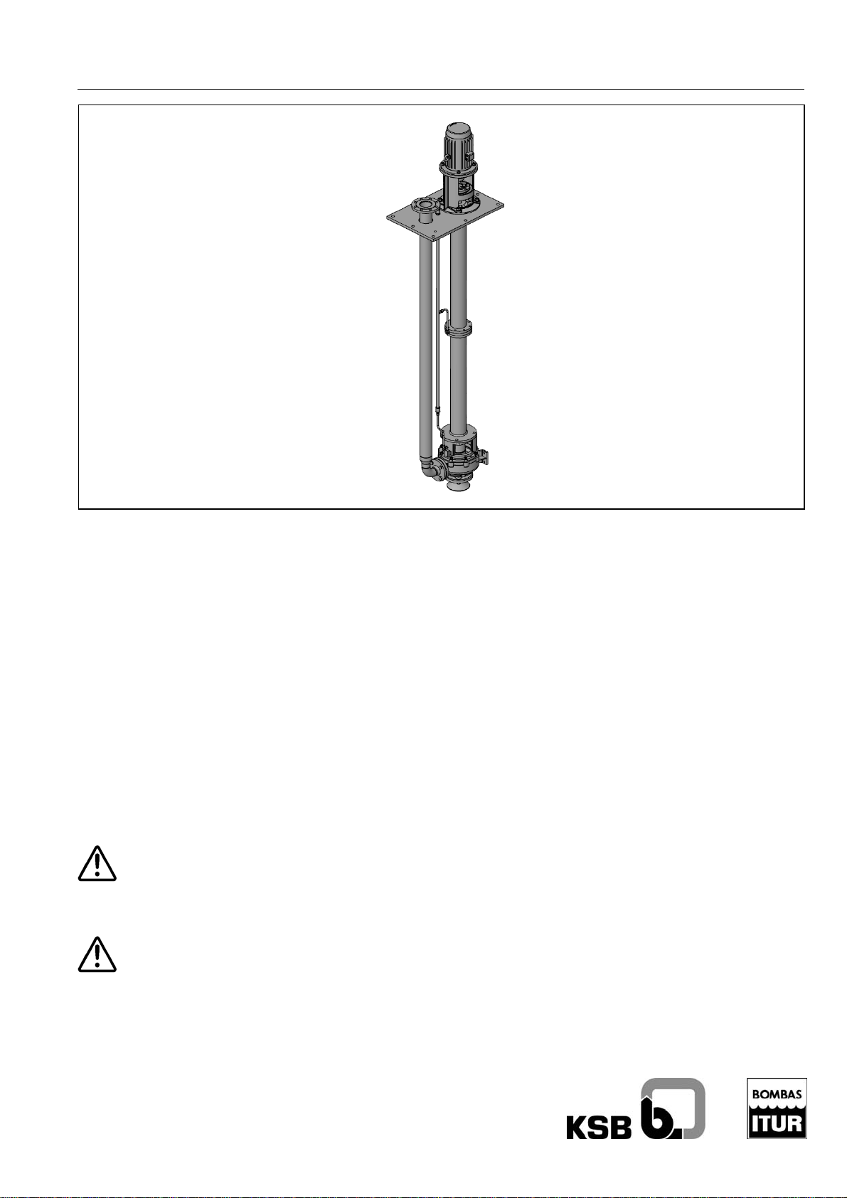
KSB RWCN, RWCP Original Manual
Instructions manual
MIF-4900/02-I [02-2010]
RWCP, RWCN
Vertical pumps for tanks
Original manual
This manual contains important instructions and warnings.
You must read them before mounting, making the electrical
connections and starting up. You must also co mply with the
instructions for the components related to this pump.
You should also remember that it is essential to keep this
Manual close to the motor pump equipment.

Index
RWCP, RWCN
GENERAL.................................................................. 3
1
2 SAFETY ..................................................................... 3
2.1 MARKING OF WARNINGS IN THIS MANUAL..................... 3
2.2 PERSONNEL QUALIFICATIONS AND INSTRUCTION.......... 3
2.3 RISKS OF FAILING TO COMPLY WITH THE SAFETY
INSTRUCTIONS
................................................................. 3
2.4 CONSCIENTIOUS SAFETY AT WORK............................. 3
2.5 SAFETY INSTRUCTIONS FOR USERS AND SERVICE
PERSONNEL
.................................................................... 3
2.6 SAFETY INSTRUCTIONS FOR MAINTENANCE, INSPECTION
AND ASSEMBLY WORK
....................................................... 3
2.7 MODIFICATIONS AND ARBITRARY MANUFACTURE OF
SPARE PARTS
.................................................................. 4
2.8 UNAUTHORISED OPERATION MODES ........................... 4
2.9 WARNINGS FOR EQUIPMENT WITH MARKING ...... 4
3 TRANSPORT AND STORAGE.................................. 5
3.1 TRANSPORT AND HANDLING ...................................... 5
3.2 PROVISIONAL STORAGE/CONSERVATION..................... 5
4 GROUP DESCRIPTION............................................. 5
4.1 GENERAL DESCRIPTION ............................................ 5
4.2 DENOMINATION........................................................ 5
4.3 FORM OF CONSTRUCTION ......................................... 5
4.4 FORCES AND MOMENTS PERMITTED ........................... 6
5 INSTALLATION ......................................................... 7
5.1 CHECK BEFORE ASSEMBLY........................................ 7
5.2 GROUP POSITIONING ................................................ 7
5.2.1 Vertical groups...............................................7
5.3 PIPE JOINT .............................................................. 7
5.3.1 Auxiliary connections.....................................8
5.4 ELECTRICAL CONNECTION:........................................ 8
5.4.1 Motor connection...........................................8
5.4.2 Time relay adjustment...................................9
5.4.3 Rotation direction. Check...............................9
6 START UP.................................................................. 9
6.1 FIRST START-UP ...................................................... 9
6.1.1 Lubricant........................................................9
6.1.2 Filling (priming) of the pump..........................9
6.1.3 Final control...................................................9
6.1.4 Impeller adjustment.....................................10
6.1.5 Start-up........................................................10
6.1.6 Shutdown.....................................................10
6.2 SERVICE LIMITS ......................................................10
6.2.1 Switching frequency ....................................10
6.2.2 Temperature of the liquid to be pumped......10
6.2.3 Density of the liquid to be pumped ..............10
6.2.4 Temperature of the liquid to be pumped......11
6.2.5 Maximum pump speed ................................11
6.3 STARTING UP AFTER STORAGE .................................11
7 MAINTENANCE/CONSERVATION.......................... 11
7.1 GENERAL INSTRUCTIONS.........................................11
7.2 MAINTENANCE/INSPECTION ..................................... 11
7.2.1 Checking instructions.................................. 11
7.2.2 Lubrication .................................................. 11
7.3 EMPTYING/DRAINAGE ............................................. 12
7.4 DI MANTLING......................................................... 12 S
7.4.1 Fundamental instructions/observations....... 12
7.4.2 Coupling...................................................... 12
7.4.3 Mechanical seal (when fitted)...................... 12
7.4.4 Packing (where fitted) .................................12
7.4.5 Pump .......................................................... 13
7.5 ASSEMBLY............................................................. 13
7.5.1 Coupling...................................................... 13
7.5.2 Mechanical seal (when fitted)...................... 14
7.5.3 Packing (where fitted) .................................14
7.5.4 Pump .......................................................... 14
7.5.5 Tightening torque of the screws/nuts.......... 14
7.6 RECOMMENDED SPARE PARTS .................................15
7.7 PREVENTATIVE MAINTENANCE.................................. 15
8 TROUBLE-SHOOTING ............................................16
9 ANNEXES.................................................................17
9.1 SECTIONAL PLANS ..................................................17
9.2 MINIMUM SUBMERGENCE CHART AND EXTERIOR
BEARINGS WATER CONSUMPTION
. .................................... 19
2
1 General
Note
manufactured with great care and put through continuous
Quality Control. The present Instructions Manual will provide
you with knowledge of the pump and the ways it can be
applied.
It contains important instructions to operate the pump
appropriately and profitably. It is important to comply with the
manual in order to guarantee reliability and a long useful life
for the pump, whilst avoiding any possible risks.
This manual does not include any local regulations or any
instructions with regards to assembly personnel, which the
user shall be responsible for.
(rpm), density, pressure and temperature, and with regards to
the motor power or anything else set out in the instructions
manual and contractual documentation. Check with the
manufacturer as appropriate.
The factory plate shows the model/size, the main service data
and the manufacture number of the pump. Please include
these data in any queries, subsequent orders or requests for
spare parts.
If you require any additional information or have problems with
regards to failures, please contact the nearest KSB ITUR
service.
This KSB ITUR pump has been developed in
line with state-of-the-art technology,
This group cannot be used in conditions in excess of
those established in the technical documentation
with regards to the liquid to be pumped, flow, speed
2 Safety
This instructions manual contains fundamental instructions
which must be complied with in assembly, service and
maintenance. It must be read by assembly personnel,
competent technical personnel and users before installing and
starting up, and it must be available at all times at the place of
location of the machine.
Proceed not only in line with this main safety chapter, but also
observing the instructions described in other similarly
important safety points.
2.1 Marking of warnings in this manual
The instructions which may involve hazard if not observed are
highlighted with the following general symbols:
Safety instructions which may involve a hazard to
people and facilities if not complied with in
accordance with ISO 7000-0434.
Safety instructions to prevent electrical hazards in
accordance with IEC 417-5036.
Note
with.
Safety instructions to prevent the risk of explosion.
Only applicable to groups with ATEX plate, specially
designed to satisfy Directive 94/9/EC on the prevention of the
risk of explosion.
The details shown directly on the machine, such as:
- Rotation direction arrow
- Fluid connection identifications
These must be observed, and conserved in a manner which
ensures they are legible.
Safety instructions which may affect the
equipment and its operation if not complied
RWCP, RWCN
2.2 Personnel qualifications and instruction
All Service, Maintenance, Inspection and Assembly personnel
must be duly qualified. The terms regarding responsibility,
competence and supervision of personnel must be regulated
by the user in an exact manner.
Any personnel lacking appropriate know-how must be duly
instructed. This preparation can be obtained upon request by
the machine user to the manufacturer or supplier of the
machine.
Finally, the user must ensure that all personnel have fully
understood the content of the instructions manual.
2.3 Risks of failing to comply with the safety
instructions
Failure to comply with the safety instructions may lead to risks
both for people, the environment and the machine, and may
lead to the loss of any entitlement to claims.
In particular, failure to comply may cause the following
hazards:
- Failure of important machine/facility functions.
- Failure of the prescribed maintenance and conservation
methods.
- Personal hazard resulting from electrical, mechanical or
chemical effects.
- Danger to the environment due to escaping noxious
products.
2.4 Conscientious safety at work
The safety instructions contained in this Manual must be
observed, as must international prescriptions on Health and
Safety at Work and any possible Safety Regulations at the
workplace of the user.
2.5 Safety instructions for users and service
personnel
The operator is responsible for keeping the
temperature of the fluid within the pump classification
temperature limits.
- The installer must ensure that the parts of the machine
which may create danger due to heat or cold are
protected against accidental contact. The operator shall
check as well that the coupling guard is in place and
firmly secured.
- The contact protections of moving parts (e.g. couplings)
must not be removed whilst the machine is in service.
- Provide the personnel with protective equipment and
make sure it is used.
- Any possible leaks (e.g. through the shaft sealing) of
hazardous products must be channelled in such a
manner as they do not present any risk to people or the
environment, in line with corresponding legislation.
- Follow safety instructions due to use of power. In this
respect refer to the applicable national safety regulations
and/or regulations issued by the energy supply comp
2.6 Safety instructions for maintenance,
inspection and assembly work
The user must ensure that all maintenance, inspection and
assembly tasks are carried out by authorised, qualified,
specialised personnel who have been sufficiently informed
through careful study of the instructions manual.
3
It is a fundamental principle that any work on the machine
must be carried out whilst it is shutdown. It is essential to
respect the pump shutdown procedure described in the
instructions manual.
When the pump is stopped it is liable to remain under
pressure. The pump frame must have returned to
environmental temperature. Before dismantling it, is must be
depressurised by making drain openings (or air vents) leading
to a safe area.
All pumps or motor pumps which pump hazardous materials
must be decontaminated.
Connect an earth conductor to the metal casing of the pump
or baseplate if the fluid handled is electrostatically charged.
Never connect the earth of the electric welding equipment to
pump or baseplate.
As soon as the work is complete, all safety and protection
devices must be installed and put into operation.
Before starting up again, all that described in the First Start-Up
section must be fulfilled.
Due to the fact that the unit contains small parts such as
nuts, screws, etc., whose accidental contact may lead to
small cuts on the hands, operators are recommended to
use gloves when handling.
The following additional risk-prevention instructions
shall be fulfilled:
The pumped liquid may cause injuries, burns, poisoning, etc. It
is therefore necessary:
- To check the temperature and amount of leaks occurring
at the mechanical seal or packing area. Conduct such
leaks to a safe area through a controlled drainage
system, specially indicated for the case of break of
mechanical seal.
- To take appropriate measures to avoid direct contact with
the pumped liquid when it is necessary to prime or fill the
pump or unit.
- Before dismantling the pump, if the liquid is toxic or
dangerous, it must be decontaminated. For this purpose
the unit must be cleaned inside by introducing a cleaning
liquid into the pump and emptying it subsequently
through the drainage connection. The cleaning liquid
must not create hazardous situations and must be
compatible with the pump components (CONSULT)
- To take appropriate measures to avoid contact with the
pump if liquids are pumped at temperatures over 40ºC.
- In the event of a liquid with high steam pressure being
used, beware of the danger of explosion due to pressure
confinement with the pump stopped. This confinement
must be avoided by opening inlet or discharge valves, or
by providing a properly conducted air-vent connection in
the pump discharge for liquid evacuation.
For rotating parts:
- The pump should never work without its coupling guard
in place and firmly secured.
- Do not wear loose or baggy clothing or wear long hair
loose near rotation areas to avoid clothes or hair getting
caught and causing serious accidents.
- Do not force jammed rotating parts manually when the
pump is in operation.
When the pump is joined to considerably long piping,
waterhammer may occur when it is stopped. Should this arise,
appropriate anti-waterhammer elements must be put in place.
All the safety regulations indicated by the pump drive
manufacturer must be observed and complied with.
Inappropriate installation may lead to the unit breaking and
consequent risks to persons and/or the environment. It is
therefore necessary to:
- Vent the pumps appropriately before operation, checking
that the pump is full of liquid.
- Check that the pump discharge and suction valves are
fully open and that there is no dirt or foreign bodies in the
piping.
Regarding overload conditions:
- Do not exceed the maximum permitted values
(temperature, suction pressure, discharge pressure,
rpm.) indicated in this instructions manual, offer and
technical catalogue.
- Do not exceed the maximum loads permitted on the
suction and discharge connections.
- The pumps must only be used in the conditions and with
the liquid indicated in the offer and/or order.
An unforeseen failure in the drive power may lead to danger
due to spontaneous start-up of the unit; it is up to the
customer to take the necessary steps to avoid this.
When the CONTROL SYSTEM is not supplied by KSB ITUR,
the customer is responsible for the entire machine complying
with the machine safety directive, including these controls
RWCP, RWCN
2.7 Modifications and arbitrary manufacture of
spare parts
The machine must not be modified or changed without prior
agreement from the manufacturer. Only original spare parts
and accessories approved by the manufacturer can guarantee
safety. The use of other parts invalidates any liability of KSB
ITUR for consequential damage.
2.8 Unauthorised operation modes
The safe service of the supplied pump can only be guaranteed
through correct use, in line with section 0 of the Instructions
Manual. The operation limits established in the Datasheet
must not be exceeded under any circumstance.
2.9 Warnings for equipment with marking
KSB ITUR pumps marked with the ATEX plate are
valid for group II category 2 and 3, zones 1, 21, 2 and
22 temperature class as shown on the plate and Conformity
Certificate.
Reliability may be lost through incorrect use, poor
connections or any modifications, however small.
It is necessary to take into account the rules on the
connection and use of electrical devices in hazardous
areas, in particular national regulations on installation. Only
qualified personnel who are familiar with these rules should
handle this type of machine.
Any repair made by the end user, unless explicitly
approved by KSB ITUR, shall release the
manufacturer from any liability relating to Directive 94/9/EC.
Individual pieces supplied as spare parts must be originals,
supplied and checked by KSB ITUR.
4
P
3 Transport and storage
3.1 Transport and handling
The transport and handling of the equipment must be
carried out using suitable means in line with the
weight to be supported. The weight is generally
shown on the delivery note or on the data plate. If it is not, and
the equipment cannot be handled safely, please contact KSB
ITUR.
Remember that the equipment should never be lifted using the
ring bolts of each of the elements, e.g. the motor and pump
ring bolts, which are exclusively for independent transport.
Note
couplings.
Note
motor and pump support.
Note
the well on the ground, place a wood plug at the height of the
casing in order to prevent the suction hood from being a
support point for the pump.
It is also important not to use the pump and
pipe flanges or joining elements, e.g.
If the equipment is to be lifted using straps,
these must always be run underneath the
Do not position the pump on the filter/suction
hood. When positioning the pump outside of
4 Group description
4.1 General description
Vertical centrifugal pump designed for wells, ditches and
tanks. For neutral or aggressive liquids with significant solid
content.
RWCP, RWCN
When the pumps are dismounted from their transport
pallet, suitable means must be used to ensure the
stability of the equipment, until it is finally secured at
its definitive location.
3.2 Provisional storage/conservation
During provisional storage, it is only necessary to protect with
preservation products those low alloy parts in contact with the
liquid (e.g. grey cast, nodular cast, etc). Preservation products
available on the sector market can be used, in line with the
manufacturer's instructions on application and disposal.
The pump, or motor pump, shall be deposited in a dry site
where the relative humidity is as constant as possible.
When stored outside, it is necessary to keep the pump/motor
pump in an impermeable box, ensuring it does not come into
contact with external humidity.
Note
openings must remain closed, and must not be opened until
necessary during assembly!
The shiny (mechanised) parts and surfaces of the pump must
be protected from corrosion using silicone-free oil or grease.
in vertical position and disconnected.
Protect the stored product from humidity, dirt,
parasites and unauthorised access! All
The electric motor must be disconnected, the
connection cables removed and the terminal box
closed with its cover on. The switchboards must be
RWC
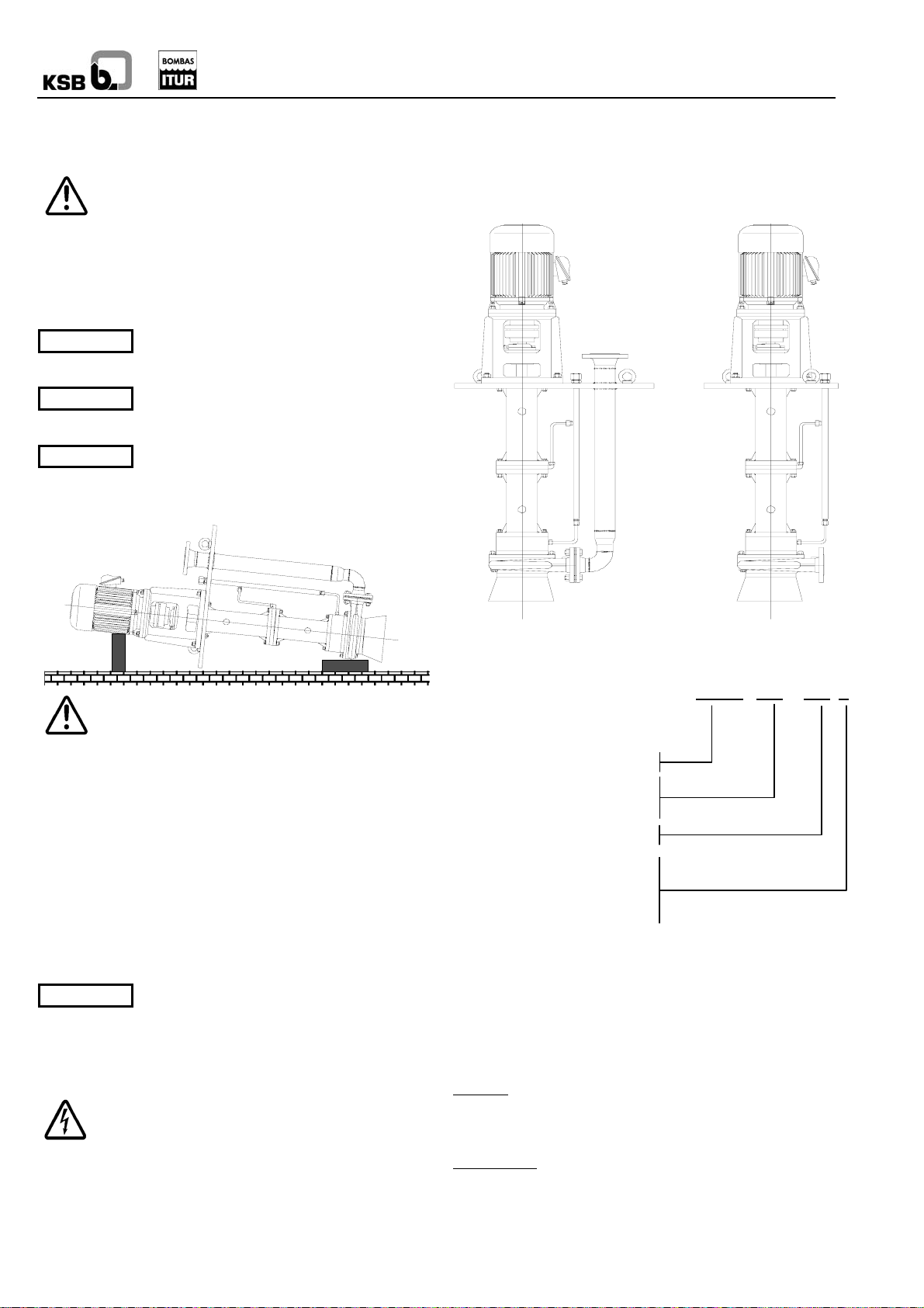
4.2 Denomination
RWCP
RWCN
- 100 / 250 V
Discharge nozzle DN
Series
[mm]
DN impeller [mm]
Impeller type:
- A (semi-open)
- C (channel)
- V (vortex)…
4.3 Form of construction
Volute pump casing with axial suction and radial impulsion.
Single-stage impeller semi-open, channel or vortex. Suction
hood.
The RWCP series has a discharge pipe to the outside of the
base plate.
The RWCN series does not have a discharge pipe.
Bearings
grease-lubricated ballbearings or friction bearings lubricated
by the pumped liquid (when possible) or through the exterior
injection of liquid or grease.
Shaft sealing
retainer. This can be done optionally using a packing or
mechanical seal.
: Both series are fitted with two classes of bearing:
: The standard sealing system is by way of a
5
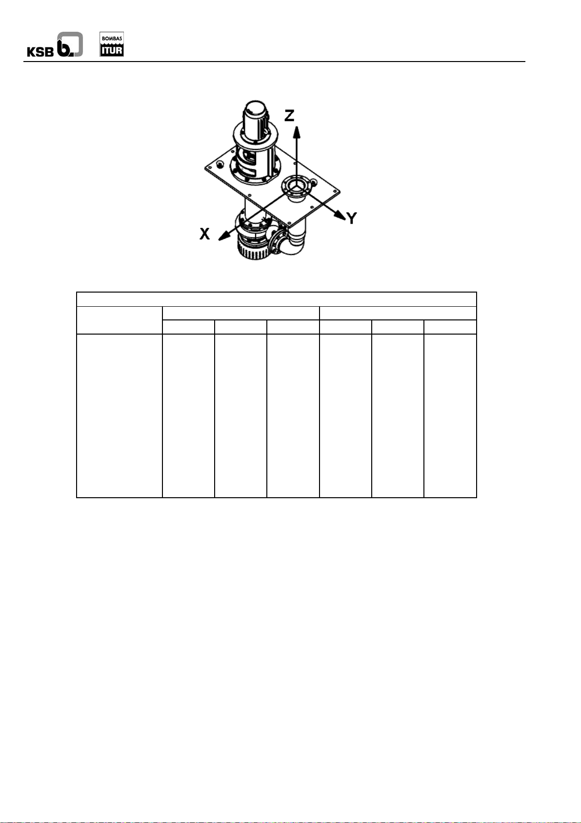
4.4 Forces and moments permitted
Maximum permitted strain in the upper discharge flange, RWCP series exclusively
DN
32 – 1 ¼” 630 510 540 450 510 660
40 – 1 ½” 750 600 660 540 630 780
50 – 2” 990 810 900 600 690 840
65 – 2 ½” 1260 1020 1110 660 720 900
80 – 3” 1500 1230 1350 690 780 960
100 – 4” 2010 1620 1800 750 870 1050
125 – 5” 2370 1920 2130 900 1140 1260
150 – 6” 3000 2430 2700 1050 1230 1500
200 – 8” 4020 3240 3600 1380 1590 1950
250 – 10” 5010 4050 4470 1890 2190 2670
300 – 12” 6000 4830 5370 2580 2970 3630
350 – 14” 6990 5640 6270 3300 3810 4650
400 – 16” 7980 6450 7170 4140 4770 5820
The RWCN series does not admit any strain on the discharge flang e.
Fz Fx Fy Mz Mx My
Force [N] Moment [N·m]
RWCP, RWCN
6
 Loading...