

KSB RPH Series Operating Instructions Manual
Operating instructions
1316.8014/2-10 G3
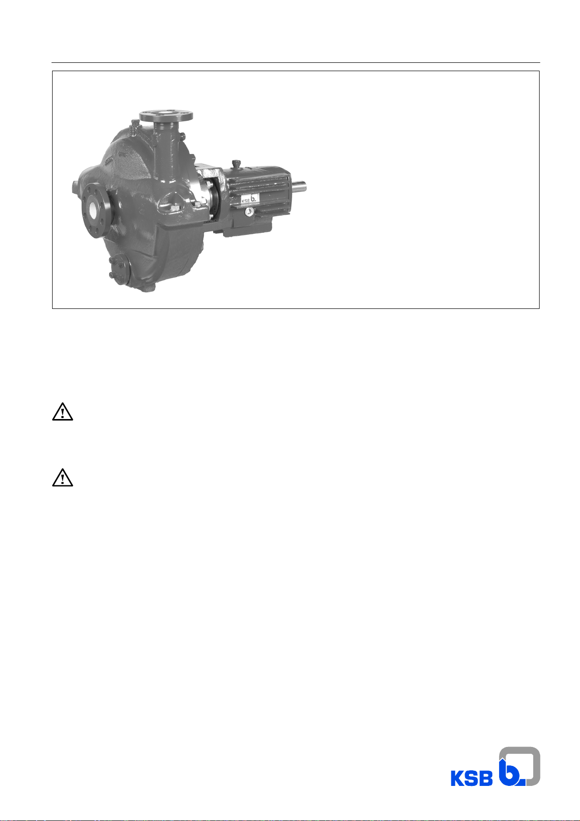
RPH
RPH process pump
to API 610, 10th edition and DIN ISO 13709
and Directive 94/9/EC
Standard bearing assemblies B 02 to B 06
Tandem bearing assemblies B 02 to B 06
cooled/uncooled
Mechanical seal
Made by KSB
Works No.: __________________________________
Type series: __________________________________
These operating instructions contain fundamental
information and precautionary notes. Please read
the manual thoroughly prior to installation of unit,
connection to the power supply and commissioning. It is
imperative to comply with all other operating instructions
referring to components of this unit.
This manual shall always be kept close to the unit’s
location of operation or directly on the pump set.

Contents
Page
1 General 4
2 Safety 4
2.1 Marking of instructions in the manual 4
2.2 Personnel qualification and training 4
2.3 Non-compliance with safety instructions 4
2.4 Safety awareness 4
2.5 Safety instructions for the operator / user 4
2.6 Safety instructions for maintenance,
inspection and installation work
2.7 Unauthorized modification and manufacture
of spare parts
2.8 Unauthorized modes of operation 5
2.9 Explosion protection 5
2.9.1 Unit fill 5
2.9.2 Marking 5
2.9.3 Checking the direction of rotation 5
2.9.4 Pump operating mode 5
2.9.5 Temperature limits 5
2.9.6 Maintenance 6
3 Transport and interim storage 6
3.1 Transport 6
3.2 Interim storage/Preservation 6
4 Description of the product and
accessories
4.1 Technical specification 6
4.2 Designation 6
4.3 Design details 6
4.3.1 Pump casing 6
4.3.2 Impeller 7
4.3.3 Shaft seal 7
4.3.4 Bearings 7
4.3.5 Permissible forces and moments at the
pump nozzles
4.3.6 Noise characteristics 8
4.4 Accessories 8
4.5 Dimensions and weights 8
5 Installation at site 8
5.1 Safety regulations 8
5.2 Checks to be carried out prior to installation 8
5.3 Installing the pump / unit 9
5.3.1 Aligning the pump / drive 9
5.3.2 Place of installation 9
5.4 Connecting the piping 10
5.4.1 Auxiliary connections 10
5.4.2 Coupling guard 10
5.5 Final check 10
5.6 Connection to power supply 10
6 Commissioning, start-up / shutdown 10
6.1 Commissioning 10
6.1.1 Lubricants 10
6.1.2 Shaft seal 11
6.1.3 Priming the pump and checks to be carried
out
6.1.4 Checking the direction of rotation 11
6.1.5 Cleaning the plant piping 11
6.1.6 Start-up strainer 11
5
6.1.7 Start-up 12
6.1.8 Shutdown 12
5
6.2 Operating limits 12
6.2.1 Temperature of fluid handled / ambient
temperature
6.2.2 Switching frequency 12
6.2.3 Density of fluid pumped 12
6.2.4 Abrasive fluids 12
6.2.5 Minimum/Maximum Flow 12
6.3 Shutdown / Storage /
Preservation
6.3.1 Storage of new pumps 12
6.3.2 Measures to be taken for prolonged
shutdown
6.4 Returning to service after storage 13
6
7 Servicing / maintenance 13
7.1 General instructions 13
7.2 Servicing / inspection 13
7.2.1 Supervision of operation 13
7.2.2 Lubrication and lubricant change 13
7.3 Drainage / disposal 13
7.4 Dismantling 14
7.4.1 Fundamental instructions and
7
7.4.2 Dismantling (general) 14
7.5 Reassembly 14
7.5.1 General instructions 14
7.5.2 Reassembly (general) 15
7.5.3 Tightening torques 15/16
7.5.4 Mechanical seal installation 16
7.5.5 Clearances 17
7.6 Spare parts stock 18
7.6.1 Recommended spare parts stock for 2
7.6.2 Interchangeability of pump components 19
8 Trouble-shooting 20
9 General assembly drawings/lists of
9.1 Material class S, cooled/uncoooled 21
9.2 Bearing bracket B 06, cooled/uncooled 22
9.3 Design variants 23
recommendations
years’ operation
components
RPH
Page
11
12
12
13
14
18
21-24
2

Index
Section Page
Abrasive fluids 6.2.4 12
Accessories 4.4 8
Aligning the pump / drive 5.3.1 9
Auxiliary connections 5.4.1 10
Bearing bracket B 06, cooled/uncooled 9.2 22
Bearings 4.3.4 7
Checking the direction of rotation 2.9.3/
6.1.4
Checks to be carried out prior to installation 5.2 8
Cleaning the plant piping 6.1.5 11
Clearances 7.5.5 17
Commissioning 6.1 10
Commissioning, start-up / shutdown 6 10
Connecting the piping 5.4 10
Connection to power supply 5.6 10
Coupling guard 5.4.2 10
Density of fluid pumped 6.2.3 12
Description of the product and accessories 4 6
Design details 4.3 6
Design variants 9.3 23
Designation 4.2 6
Dimensions and weights 4.5 8
Dismantling 7.4 14
Dismantling (general) 7.4.2 14
Drainage / disposal 7.3 13
Explosion protection 2.9 5
Final check 5.5 10
Fundamental instructions and
recommendations
General 1 4
General assembly drawings/lists of
components
General instructions 7.1/
Impeller 4.3.2 7
Installation at site 5 8
Installing the pump / unit 5.3 9
Interchangeability of pump components 7.6.2 19
Interim storage/Preservation 3.2 6
Lubricants 6.1.1 10
Lubrication and lubricant change 7.2.2 13
Maintenance 2.9.6 6
Marking 2.9.2 5
Marking of instructions in the manual 2.1 4
Material class S, cooled/uncoooled 9.1 21
Measures to be taken for prolonged
shutdown
Mechanical seal installation 7.5.4 16
Minimum/Maximum Flow 6.2.5 12
7.4.1 14
9 21-24
7.5.1
6.3.2 13
11
13/
14
Noise characteristics 4.3.6 8
Non-compliance with safety instructions 2.3 4
Operating limits 6.2 12
Permissible forces and moments at the
pump nozzles
Personnel qualification and training 2.2 4
Place of installation 5.3.2 9
5/
Priming the pump and checks to be carried
out
Pump casing 4.3.1 6
Pump operating mode 2.9.4 5
Reassembly 7.5 14
Reassembly (general) 7.5.2 15
Recommended spare parts stock for
2 years’ operation
Returning to service after storage 6.4 13
Safety 2 4
Safety awareness 2.4 4
Safety instructions for maintenance,
inspection and installation work
Safety instructions for the operator / user 2.5 4
Safety regulations 5.1 8
Servicing / inspection 7.2 13
Servicing / maintenance 7 13
Shaft seal 4.3.3/
Shutdown 6.1.8 12
Shutdown / Storage /
Preservation
Spare parts stock 7.6 18
Start-up 6.1.7 12
Start-up strainer 6.1.6 11
Storage of new pumps 6.3.1 12
Supervision of operation 7.2.1 13
Switching frequency 6.2.2 12
Technical specification 4.1 6
Temperature limits 2.9.5 5
Temperature of fluid handled / ambient
temperature
Tightening torques 7.5.3 15/16
Transport 3.1 6
Transport and interim storage 3 6
Trouble-shooting 8 20
Unauthorized modes of operation 2.8 5
Unauthorized modification and manufacture
of spare parts
Unit fill 2.9.1 5
RPH
Section Page
4.3.5 7
6.1.3 11
7.6.1 18
2.6 5
6.1.2
6.3 12
6.2.1 12
2.7 5
11
7/
3

RPH
1 General
Caution
is manufactured with utmost care and subject to continuous
quality control.
These operating instructions are intended to facilitate
familiarization with the unit and its designated use.
The manual contains important information for reliable, proper
and efficient operation. Compliance with the operating
instructions is of vital importance to ensure reliability and a long
service life of the unit and to avoid any risks.
These operating instructions do not take into account local
regulations; the operator must ensure that such regulations are
strictly observed by all, including the personnel called in for
installation.
This pump / unit must not be operated beyond the limit
values for the fluid handled, capacity, speed, density,
pressure, temperature and motor rating specified in the
technical documentation. Make sure that operation is in
accordance with the instructions laid down in this manual or in
the contract documentation. Contact the manufacturer, if
required.
The name plate indicates the type series / size, main operating
data and works number; please quote this information in all
queries, repeat orders and particularly when ordering spare
parts.
If you need any additional informationor instructions exceeding
the scope of this manual or in case of damage please contact
KSB’s nearest customer service centre.
Noise characteristics see section 4.3.6.
This KSB product has been developed in
accordance with state-of-the-art technology; it
2 Safety
These operating instructions contain fundamental information
which must be complied with during installation, operation,
monitoring and maintenance. Therefore this operating manual
must be read and understood both by the installing personnel
and the responsible trained personnel / operators prior to
installation and commissioning, and it must always be kept
close to the location of operation of the machine / unit for easy
access.
Not only must the general safety instructions laid down in this
chapter on ”Safety” be complied with, but also the safety
instructions outlined under specific headings, particularly if the
pump/unit is operated in potentially explosive atmospheres
(see section 2.9).
The word
Caution
is used to introduce safety instructions whose non-observance
may lead to damage to the machine and its functions.
Instructions attached directly to the machine, e.g.
- arrow indicating the direction of rotation
- markings for fluid connections
must always be complied with and be kept in a perfectly legible
condition at all times.
2.2 Personnel qualification and training
All personnel involved in the operation, maintenance,
inspection and installation of the unit must be fully qualified to
carry out the work involved.
Personnel responsibilities, competence and supervision must
be clearly defined by the operator. If the personnel in question
is not already in possession of the requisite know-how,
appropriate training and instruction must be provided. If
required, the operator may commission the manufacturer /
supplier to take care of such training. In addition, the operator
is responsible for ensuring that the contents of the operating
instructions are fully understood by the responsible personnel.
2.3 Non-compliance with safety instructions
Non-compliance with safety instructions can jeopardize the
safety of personnel, the environment and the machine / unit
itself. Non-compliance with these safety instructions will also
lead to forfeiture of any and all rights to claims for damages.
In particular, non-compliance can, for example, result in:
- failure of important machine/system functions,
- failure of prescribed maintenance and servicing practices,
- hazard to persons by electrical, mechanical and chemical
effects as well as explosion,
- hazard to the environment due to leakage of hazardous
substances.
2.4 Safety awareness
It is imperative to comply with the safety instructions contained
in thismanual, the relevant nationaland international explosion
protection regulations, health and safety regulations and the
operator’s own internal work, operation and safety regulations.
Ex symbol relates to additional requirements which
must be adhered to when the pump is operated in
potentially explosive atmospheres.
2.1 Marking of instructions in the manual
The safety instructions contained in this manual whose
non-observance might cause hazards to persons are specially
marked with the symbol
general hazard sign to ISO 7000-0434
the electrical danger warning sign is
safety sign to IEC 417 - 5036.,
and special instructions concerning explosion protection are
marked
4
2.5 Safety instructions for the operator / user
- Any hot or cold components that could pose a hazard must
be equipped with a guard by the operator.
- Guards which are fitted to prevent accidental contact with
moving parts (e.g. coupling) must not be removed whilst the
unit is operating.
- Leakages (e.g. at the shaft seal) of hazardous fluids
handled (e.g. explosive,toxic, hot) must be contained so as
to avoid any danger to persons or the environment. All
relevant laws must be heeded.
- Electrical hazards must be eliminated. (In this respect refer
to the relevant safety regulations applicable to different
countries and/or the local energy supply companies.)
- Any components in contact with the fluid pumped,
especially in the case of abrasive fluids, shall be inspected
for wear at regular intervals and replaced by original spare
parts (see section 2.7) in due time.
If the pumps/units are located in potentially explosive
atmospheres, it is imperative to make sure that
unauthorized modes of operation are prevented.
Non-compliance may result in the specified temperature limits
being exceeded.
RPH
2.6 Safety instructions for maintenance,
inspection and installation work
The operator is responsible for ensuring that all maintenance,
inspection and installation work be performed by authorized,
qualified specialist personnel who are thoroughly familiar with
the manual.
The pump must have cooled down to ambient temperature,
pump pressure must have been released and the pump must
have been drained.
Work on the machine / unit must be carried out only during
standstill. The shutdown procedure described in the manual for
taking the unit out of service must be adhered to without fail.
Pumps or pump units handling fluids injurious to health must be
decontaminated.
Immediately following completion of the work, all
safety-relevant and protective devices must be re-installed
and/or re-activated.
Please observe all instructions set out in the chapter on
”Commissioning” before returning the unit to service.
2.7 Unauthorized modification and
manufacture of spare parts
Modifications or alterations of the equipment supplied are only
permitted after consultation with the manufacturer and to the
extent permitted by the manufacturer . Original spare parts and
accessories authorized by the manufacturer ensure safety.The
use of other parts can invalidate any liability of the manufacturer
for consequential damage.
2.8 Unauthorized modes of operation
The warranty relating to theoperatingreliability and safety of the
unit supplied is only valid ifthe equipment is used inaccordance
with its designated use as described in the following sections.
The limits stated in the data sheet must not be exceeded under
any circumstances.
2.9 Explosion protection
If the pumps/units are installed in potentially explosive
atmospheres, the measures and instructions given in
the following sections 2.9.1 to 2.9.6 must be adhered to without
fail, to ensure explosion protection.
by starting up the unfilled pump unit, even for a short period, to
prevent temperature increases resulting from contact between
rotating and stationary components.
2.9.4 Pump operating mode
Make sure that the pump is always started up with the
suction-side shut-off valve fully open and the discharge-side
shut-off valve slightly open. However, the pump can also be
started up against a closed swing check valve. The
discharge-side shut-off valve shall be adjusted to comply with
the duty point immediately following the run-up process (see
6.1.7 ).
Pump operation with the shut-off valves in the suction
and/or discharge pipes closed is not permitted.
Caution
after a very short time, due to a rapid temperature rise in the
pumped fluid inside the pump.
Additionally, the resulting rapid pressure build-up inside the
pump may cause excessive stresses on the pump materials or
even bursting.
The minimumflows indicated in section 6.2.5 refer to water and
water-like liquids. Longer operating periods with these liquids
and at the flow rates indicated will not cause an additional
increase in the temperatures on the pump surface. However, if
the physical properties of the fluids handled are different from
water, it is essential to check if an additional heat build-up may
occur and if theminimum flow rate must therefore be increased.
To check, proceed as described in section 6.2.5.
In addition, the instructions given in section 6 of this operating
manual must be observed.
Both gland packings and mechanical seals may
exceed the specified temperature limits if run dry.
Dry running may not only result from an inadequately filled
seal chamber, but also from excessive gas content in the
fluid handled.
Pump operation outside its specified operating range may
also result in dry running.
In potentiallyexplosive atmospheres, gland packingsshall
only be used if combined with a suitable temperature
monitoring device.
In this condition, there is a risk of the pump
casing taking on high surface temperatures
2.9.1 Unit fill
It is assumed that the system of suction and discharge
lines and thus the wetted pump internals are completely
filled with the product to be handled at all times during pump
operation, so that an explosive atmosphere is prevented.
If the operatorcannot warrantthis condition, appropriate
monitoring devices must be used.
Caution
seal and the heating and cooling systems are properly filled.
2.9.2 Marking
The marking on the pump only refers to the pump part,
i.e.the coupling and motor must be regardedseparately.
The coupling must have an EC manufacturer’s declaration.The
driver must be regarded separately.
Example of marking on the pump part:
The marking indicates the theoretically available temperature
range as stipulated by the respective temperature classes.The
temperatures permitted for the individual pump variants are
outlined in section 2.9.5.
2.9.3 Checking the direction of rotation (see also 6.1.4)
If the explosion hazard also exists during the installation
phase, the direction of rotation must never be checked
In addition, it is imperative to make sure that the
seal chambers, auxiliary systems of the shaft
Ex II 2 G T1 - T5
2.9.5 Temperature limits
In normalpump operation, the highest temperatures are
to be expected on the surfaceof the pump casing, at the
shaft seal and in the bearingareas. The surface temperature at
the pump casing corresponds to the temperature of the fluid
handled.
If the pump is heated, it must be ensured that the temperature
classes stipulated for the plant are observed.
In the bearing bracket area, the unit surfaces must be freely exposed to the atmosphere.
In any case, responsibility for compliance with the
specified fluid temperature (operating temperature) lies
with the plant operator. The maximum permissible fluid
temperature depends on the temperature class to be
complied with.
The table below lists the temperature classes to EN 13463-1
and the resulting theoretical temperature limits of the fluid
handled. In stipulating these temperatures, any temperature
rise in the shaft seal area has already been taken into account.
Temperature class
to EN 13463-1:
T5
T4
T3
T2
T1
*) depending on material variant
Temperature limit of fluid handled
85 °C
120 °C
185 °C
280 °C
max. 400 °C
*)
5
Safety note:
Caution
sheet. If the pump is to be operatedat a higher temperature,the
data sheet is missing or if the pump is part of a pool of pumps,
the maximum permissible operating temperature must be
enquired from the pump manufacturer.
Based on an ambient temperature of 40 °C and proper
maintenance and operation, compliance with temperature
class T4 is warranted in the area of the rolling element bearings.
A special design is required to comply with temperature class
T6 in the bearing area. In such cases, and if ambient
temperature exceeds 40 °C, contact the manufacturer.
2.9.6 Maintenance
Only a pump unit which is properly serviced and maintai-
ned in perfect technical condition will give safe and reliable operation.
This also applies to the reliable function of the rolling element
bearings whose actual lifetime largely depends on the operating mode and operating conditions.
Regular checks of the lubricant and the running noises will prevent the risk of excessive temperatures as a result of bearings
running hot or defective bearing seals (also see section
7.2.2.2).
The correct function of the shaft sealmust be checked regularly.
Any auxiliary systems installed must be monitored, if necessary, to make sure they function correctly.
Gland packings must be tightened correctly, to prevent excessive temperatures due to packings running hot.
The permissible operating temperature of the
pump in question is indicated on the data
3 Transport and interim storage
RPH
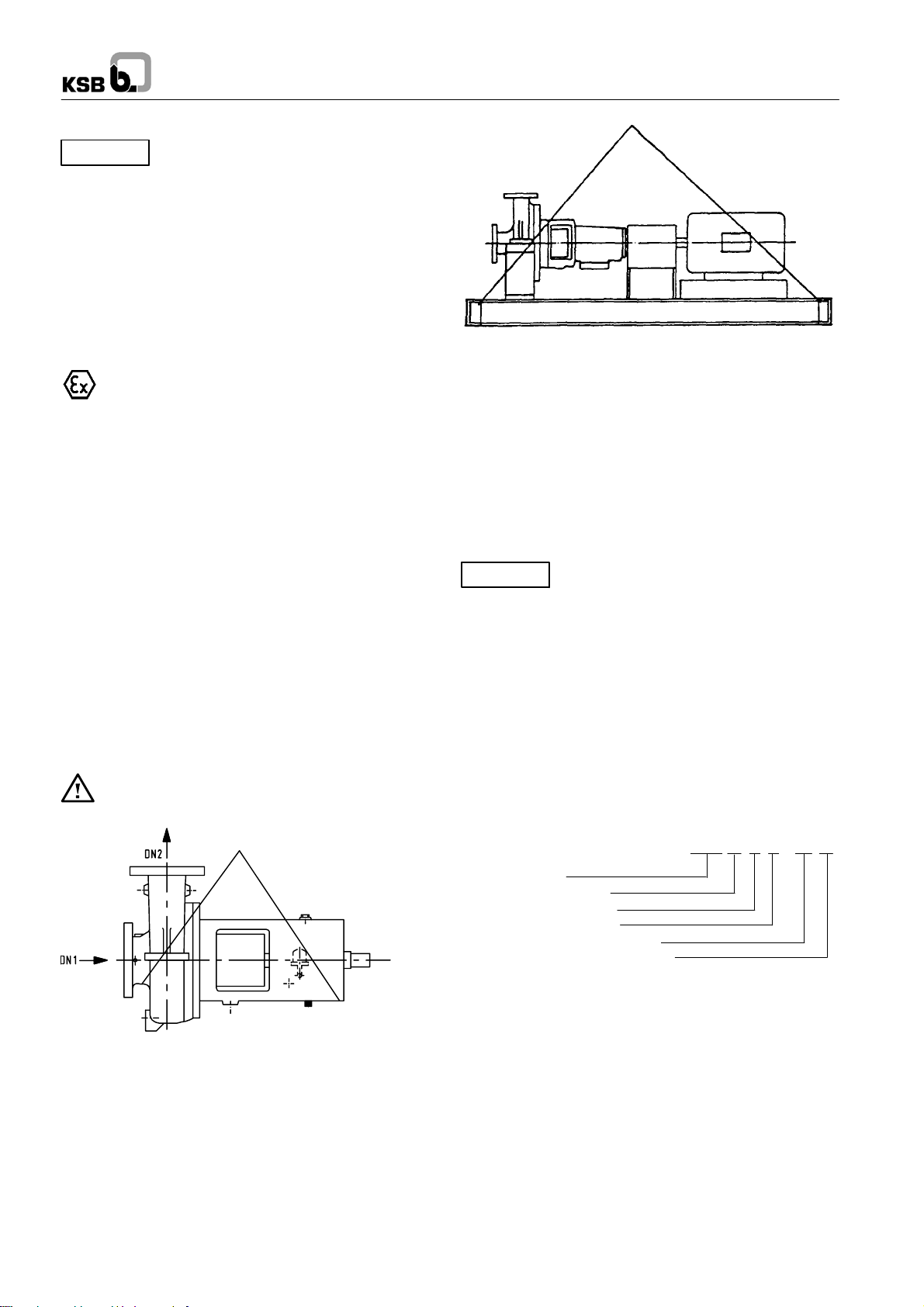
Fig. 2 Transport of the complete unit
3.2 Interim storage (indoors) / Preservation
When the unit is temporarily put into storage, only the wetted
low alloy components (e.g. JL 1040, JS 1030, A 216 Gr. WCB,
etc.) must be preserved. Commercially available preservatives
can be used for this purpose. Please observe the
manufacturer’s instructions for application/removal.
The relevant procedure is described in section 6.3.
The unit / pump should be stored in a dry room where the
atmospheric humidity is as constant as possible.
If stored outdoors, the unit and crates must be covered by
waterproof material to avoid any contact with humidity.
Caution
of the assembled unit components are closed and must onlybe
opened when required during installation.
All blank parts and surfaces of the pump are oiled or greased
(silicone-free oil and grease) to protect them against corrosion.
Protect all stored goods against humidity, dirt,
vermin and unauthorized access! All openings
3.1 Transport
Transport of the unit requires proper preparation and handling.
Always make sure that the pump or the unit remains in
horizontal position during transport and cannot slip out of the
transport suspension arrangement. Do not use a lifting sling on
the free shaft end of the pump or on the motor eyebolt.
If the pump / unit slips out of the suspension
arrangement, it may cause personal injury and damage
to property!
D00311
Fig. 1 Transport of the pump
4 Description of the product and
accessories
4.1 Technical specification
RPH pumps are used for handling the large variety of crude oil
products, mainly in refineries and chemical and petrochemical
plants.
4.2 Designation
RPH S1 I 80 - 280 B
Type series
Material variant
Version with inducer
Discharge nozzle DN
Nominal impeller dia. in mm
Special hydraulics (B-hydraulics)
4.3 Design details
Horizontal, radially split volute casing pumps in back pull-out
design, to API 610, 10th edition and ISO 13709, with radial
impeller, single-flow, single-stage, centreline pump feet.
4.3.1 Pump casing
Radially split, consisting of volute casing with casing wear ring
and casing cover. The volute casing, the casing cover and the
seal cover form the internal pump chamber.
The wall thickness of the casing includes a corrosion allowance
of 3 mm (0.12 in.).
On some pump sizes, pump casings have a double volute, in
order to compensate radial forces.
6
RPH
The casing cover is designed for holding the discharge-side
casing wear ring, ifthis is required for balancing the axial thrust.
The casing cover includes the heating or cooling chamber for
the shaft s eal, if required.
For handling combustible fluids, the pump casing must
be made of ductile material with a maximum magnesium
content of 7.5 % (see EN 13463-1). This is a standard feature
in all KSB supplies.
4.3.1.1 Position of pump feet
Generally centreline pump feet.
Centreline pump feet are generally specified by API 610,
10th edition.
Fig. 3 Casing with centreline pump feet
4.3.1.2 Nozzle positions
Axial inlet nozzle, radial discharge nozzle pointing vertically
upwards on pumps from DN 250 or
with a nominal impeller
diameter from 500 and on pump size 200-401. All other pumps
with tangential discharge nozzle pointing vertically upwards.
4.3.2 Impeller
Closed radial impeller. Impellers are supplied with wear rings
both on the suction and the discharge sideor only on the suction
side.
Wear rings are locked with grub screws.
(can also be locked with three weld spots).
Balancing:
Axial thrust is balanced by means of sealing gap and balancing
holes. The size of the balancing holes depends on the inlet
pressure.
For high inlet pressures and thus impellers withoutbalancing of
axial thrust, the discharge-side casing and impeller wear rings
are not fitted.
4.3.4.2 Bearing bracket designation
B03
Back pull-out bearing bracket
Size code (based on dimensions of seal chamber,
shaft end and bearings)
For the applicable bearing bracket version please refer to the
data sheet.
4.3.4.3 Bearings used and bearing design
KSB designation
FAG designation SKF designation
B.MUA B. MP. UA BECBM
Standard bearing assembly
Bearing
bracket
B02
B03
B05
B06
Rolling element bearing
Pump end Motor end
NU 211 C3
NU 213 C3
NU 316 C3
NU 324 C3
2 x 7309 B-MUA
2x7311B-MUA
2 x 7315 B-MUA
2 x 7224 B-MUA
Reinforced bearing assembly (triple bearing assembly)
Bearing
bracket
B02
B03
B05
B06
Rolling element bearing
Pump end Motor end
NU 211 C3
NU 213 C3
NU 316 C3
NU 324 C3
3 x 7309 B-MUA
3x7311B-MUA
3 x 7315 B-MUA
3 x 7224 B-MUA
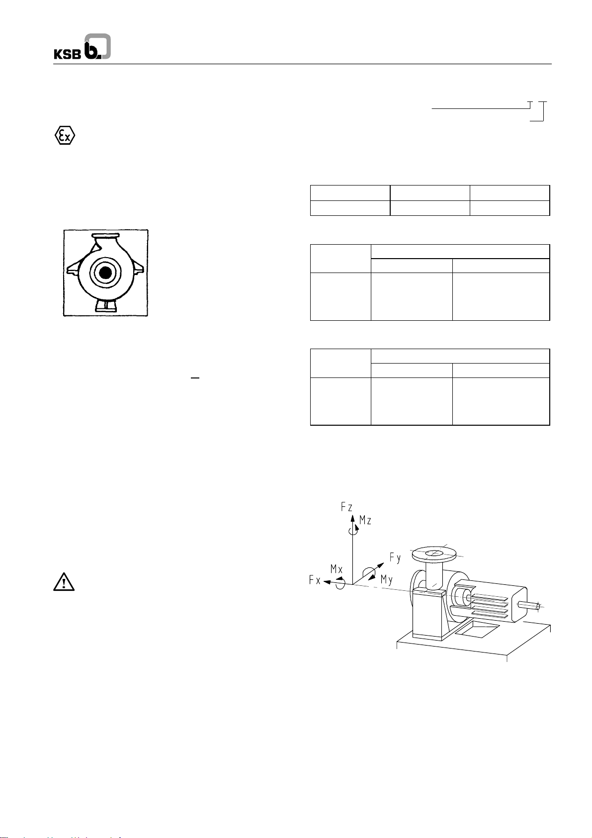
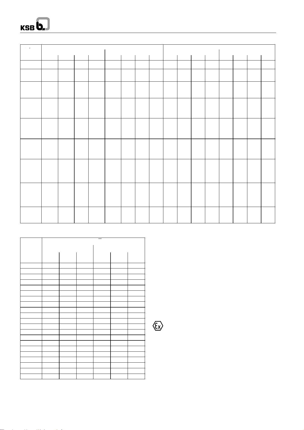
4.3.5 Permissible forces and moments at the pump
nozzles
RPH pumps are designed towithstand higher piping forces and
moments than required by API 610, tables 2-1A and 2-1B.
Forces and moments of RPH
Discharge nozzle
4.3.3 Shaft seal - Mechanical seal
Mechanical seal designs and types other than specified
herein shall only be used in exceptional cases and only
after prior consultation with the KSB factory.
The relevant seal version is shown in the mechanical seal
drawing.
4.3.4 Bearings
4.3.4.1 Design specifications
The shaft is supported byoil lubricatedrolling element bearings.
The motor end bearing is a fixed bearing whose axial bearing
clearance limits the axial movement of the rotor. The standard
motor end bearing is a paired angular contact ball bearing. For
high inlet pressures, a triple bearing assembly is used (see
section 9, design variants).
The bearing bracketsare provided withoil bath lubrication.Both
oil ring lubrication and oil mist lubrication are available as
special pump designs.
On the standard pump design, the bearing bracket is uncooled.
A cooled bearing bracket is available as special pump design.
During pump standstill the oil level can be checked against the
mark next to the oil level sight glass.
Suction nozzle
D01046
7
RPH
Pum
p
Pump
sizes
100-180
100-230
100-280
100-360
100-450
150-230
150-280
150-360
150-450
150-501
150-630
200-280
200-360
200-401
200-450
200-501
200-670
250-401
250-501
250-630
250-710
25-180
25-230
40-180
40-230
40-280
40-181
40-231
40-281
40-361
50-180
50-230
50-280
50-360
50-450
80-180
80-230
80-280
80-360
80-450
Forces (in N) Moments (in Nm) Forces (in N) Moments (in Nm)
F
1780 1430 1160 2560 920 460 710 1250 1430 1160 1780 2560 920 460 710 1250
1780 1430 1160 2560 920 460 710 1250 1430 1160 1780 2560 920 460 710 1250
1780 1430 1160 2560 920 460 710 1250 1430 1160 1780 2560 920 460 710 1250
2670 2140 1780 3860 1900 950 1440 2570 1430 1160 1780 2560 920 460 710 1250
3560 2840 2320 5110 2660 1360 2010 3600 2140 1780 2670 3860 1900 950 1440 2570
6230 4980 4090 8960 4610 2360 3530 6270 2850 2310 3560 5110 2660 1360 2010 3600
9790 7560 6230 13850 7050 3530 5150 9420 4980 4100 6230 8970 4610 2360 3530 6270
13350 10680 8900 19270 10030 4880 7590 13490 7560 6230 9790 13850 7060 3530 5150 9420
16000 13340 10680 23410 12200 5960 9220 16412 10680 8900 13340 19267 10040 4880 7600 13505
F
x
y
Suction nozzle Discharge nozzle
F
F
z
M
M
res
x
y
MzM
F
res
F
x
y
Fig. 4 Forces and moments Coordinate axes as per API 610
4.3.6 Noise characteristics
Rated
power
input P
N
(kW) 2900
Sound pressure level pA (dB)
L
Pump only Pump with motor
1450
1/min
1/min
960/760
1/min
2900
1/min
1.5 53.5 52.5 51.5 63.0 58.0 55.5
2.2 55.5 54.5 53.0 66.0 60.0 58.0
3.0 57.0 56.0 54.5 67.5 61.5 59.5
4.0 59.0 57.5 56.0 69.0 63.0 61.0
5.5 60.5 59.0 57.5 70.5 64.5 62.0
7.5 62.0 61.0 59.0 72.0 66.0 63.5
11. 0 64.0 63.0 61.0 74.0 67.5 65.0
15.0 66.0 64.5 62.5 75.0 69.0 66.5
18.5 67.0 65.5 63.5 76.0 70.0 67.5
22.0 68.0 66.5 64.5 76.5 70.5 68.0
30.0 70.0 68.0 66.0 78.0 72.0 69.5
37.0 71.0 69.5 67.0 78.5 72.5 70.0
45.0 72.0 70.5 68.0 79.5 73.5 71.0
55.0 73.0 71.5 69.0 80.0 74.0 71.5
75.0 74.5 73.0 70.5 81.0 75.5 72.5
90.0 75.5 74.0 71.0 81.5 76.0 73.0
110.0 77.0 75.0 72.0 82.0 76.5 74.0
132.0 78.0 76.0 73.0 82.5 77.0 74.5
160.0 79.0 77.0 74.0 83.5 78.0 75.0
200.0 80.0 78.0 75.0 84.0 78.5 75.5
250.0 80.5 78.5 - 84.5 79.5 -
1) measured at a distance of 1 m from the pump outline as per DIN 45635,
Part 1 and 24. Room and foundation influences have not been
included. The tolerance for these factors is 1 to 2 dB.
2) Increase for 60 Hz operation
Pump without motor: --Pump with motor:
3500min
-1
: +3dB, 1750min-1: +1dB, 1160min-1: --- dB
8
1) 2)
1450
1/min
960/760
1/min
4.4 Accessories
Coupling: flexible coupling with/without spacer
Contact guard: coupling guard
Baseplate: welded for the complete unit (pump
If a complete unit is supplied, coupling and coupling guard
are provided by the supplier.
Special accessories: as required
4.5 Dimensions and weights
For dimensions and weights please refer to the general
arrangement drawing of the pump.
5 Installation at site
5.1 Safety regulations
Equipment operated in potentially explosive
atmospheres must comply with the relevant
explosion protection regulations. This is indicated on the
pump name plate and motor name plate (see 2.9).
5.2 Checks to be carried out prior to installation
All structural work required must have been prepared in
accordance with the dimensions stated in the dimension
table / general arrangement plan.
The concrete foundations shall have sufficient strength
(min. class X0) to ensure safe and functional installation in
accordance with DIN 1045 or equivalent standards.
Make sure that the concrete foundation has set firmly before
placing the unit on it. Its surface shall be truly horizontal and
even. The foundation bolts shall be inserted in the baseplate.
RPH
F
F
M
M
z
res
x
sleeve
and motor), in torsion-resistant design
y
MzM
res
 Loading...