

KSB Rio-Eco N 65-90, Rio-Eco N 25-100, Rio-Eco N 30-100, Rio-Eco Therm N Series, Rio-Eco Therm N 30-100 Installation & Operating Manual
...Page 1

High-efficiency Circulator / Drinking Water
Pump
Rio-Eco N / Rio-Eco Z N / RioEco Therm N
Rio-Eco N 25-100, 30-100 to 80-120
Rio-Eco Z N
Rio-Eco Therm N 30-100 to 65-120
Installation/Operating Manual
Page 2

Legal information/Copyright
Installation/Operating Manual Rio-Eco N / Rio-Eco Z N / Rio-Eco Therm N
Original operating manual
All rights reserved. The contents provided herein must neither be distributed, copied, reproduced, edited or
processed for any other purpose, nor otherwise transmitted, published or made available to a third party without
the manufacturer's express written consent.
Subject to technical modification without prior notice.
© KSB Aktiengesellschaft, Frankenthal 22.08.2016
Page 3

Contents
Contents
Glossary ......................................................................................................................................... 5
1 General .......................................................................................................................................... 6
1.1 Principles .........................................................................................................................................................6
1.2 Target group ...................................................................................................................................................6
1.3 Symbols ...........................................................................................................................................................6
2 Safety ............................................................................................................................................. 7
2.1 Key to safety symbols/markings .....................................................................................................................7
2.2 General ............................................................................................................................................................7
2.3 Intended use ...................................................................................................................................................7
2.4 Personnel qualification and training .............................................................................................................8
2.5 Consequences and risks caused by non-compliance with this manual .......................................................8
2.6 Safety awareness ............................................................................................................................................8
2.7 Safety information for the operator/user .....................................................................................................8
2.8 Safety information for maintenance, inspection and installation .............................................................. 9
2.9 Unauthorised modes of operation ................................................................................................................9
3 Transport/Temporary Storage/Disposal ..................................................................................... 10
3.1 Checking the condition upon delivery ........................................................................................................10
3.2 Transport .......................................................................................................................................................10
3.3 Storage/preservation ....................................................................................................................................10
3.4 Return to supplier .........................................................................................................................................10
3.5 Disposal .........................................................................................................................................................11
4 Description of the Pump (Set) .................................................................................................... 12
4.1 General ..........................................................................................................................................................12
4.2 Designation ...................................................................................................................................................12
4.3 Name plate ....................................................................................................................................................12
4.4 Design details ................................................................................................................................................13
4.5 Configuration and function .........................................................................................................................14
4.6 Noise characteristics .....................................................................................................................................14
4.7 Scope of supply .............................................................................................................................................14
4.8 Dimensions and weight ................................................................................................................................15
5 Installation at Site ....................................................................................................................... 16
5.1 Safety regulations .........................................................................................................................................16
5.2 Checks to be carried out prior to installation .............................................................................................16
5.3 Installing the pump set ................................................................................................................................16
5.4 Connecting the piping .................................................................................................................................18
5.5 Casing/insulation ..........................................................................................................................................18
5.6 Electrical connection ....................................................................................................................................19
6 Commissioning/Start-up/Shutdown ........................................................................................... 20
Rio-Eco N / Rio-Eco Z N / Rio-Eco Therm N
3 of 36
Page 4

Contents
6.1 Commissioning/start-up ...............................................................................................................................20
6.2 Shutdown ......................................................................................................................................................27
6.3 Operating limits ............................................................................................................................................28
6.4 Shutdown/storage/preservation ..................................................................................................................28
6.5 Returning to service .....................................................................................................................................29
7 Servicing/Maintenance ............................................................................................................... 30
7.1 Servicing/inspection ......................................................................................................................................30
7.2 Drainage/cleaning ........................................................................................................................................30
7.3 Removing the pump set from the piping ...................................................................................................30
8 Trouble-shooting ........................................................................................................................ 32
9 Related Documents .................................................................................................................... 33
9.1 Sectional drawing with list of components ................................................................................................ 33
9.2 Electrical connection, overview of settings, LED displays .......................................................................... 33
10 EU Declaration of Conformity ................................................................................................... 34
Index ............................................................................................................................................ 35
4 of 36
Rio-Eco N / Rio-Eco Z N / Rio-Eco Therm N
Page 5

Glossary
Glossary
Discharge line
The pipeline which is connected to the
discharge nozzle
Noise characteristics
The noise emission to be expected, indicated as
sound pressure level LpA in dB(A)
Pump
Machine without drive, additional components
or accessories
Pump set
Complete pump set consisting of pump, drive,
additional components and accessories
Suction lift line/suction head line
The pipeline which is connected to the suction
nozzle
Rio-Eco N / Rio-Eco Z N / Rio-Eco Therm N
5 of 36
Page 6
1 General
1 General
1.1 Principles
This operating manual is supplied as an integral part of the type series and variants
indicated on the front cover. The manual describes the proper and safe use of this
equipment in all phases of operation.
The name plate indicates the type series/size and main operating data. They uniquely
identify the pump (set) and serve as identification for all further business processes.
In the event of damage, immediately contact your nearest KSB service centre to
maintain the right to claim under warranty.
Noise characteristics see (⇨ Section 4.6 Page 14)
1.2 Target group
This operating manual is aimed at the target group of trained and qualified specialist
technical personnel. (⇨ Section 2.4 Page 8)
1.3 Symbols
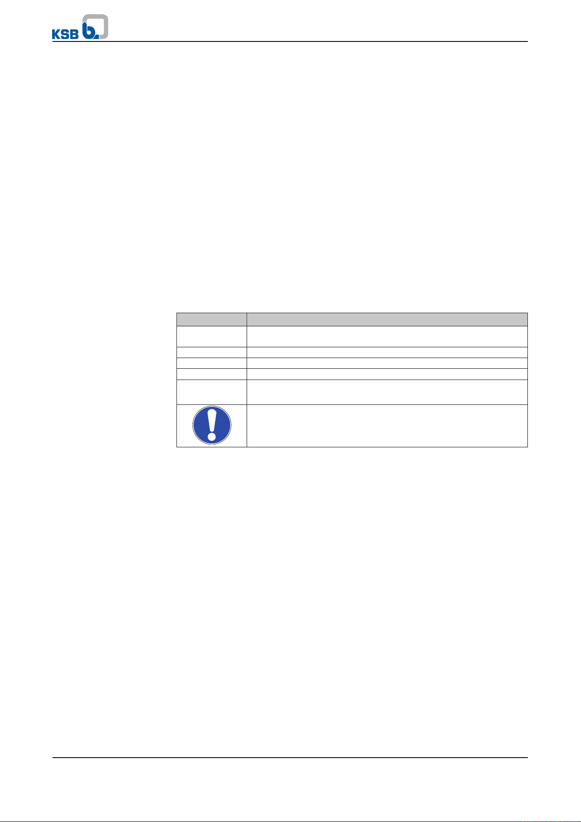
Table 1: Symbols used in this manual
Symbol Description
✓ Conditions which need to be fulfilled before proceeding with the
step-by-step instructions
⊳ Safety instructions
⇨ Result of an action
⇨ Cross-references
1.
2.
Step-by-step instructions
Note
Recommendations and important information on how to handle
the product
6 of 36
Rio-Eco N / Rio-Eco Z N / Rio-Eco Therm N
Page 7
!
DANGER
!
WARNING
CAUTION
!
DANGER
2 Safety
2 Safety
All the information contained in this section refers to hazardous situations.
2.1 Key to safety symbols/markings
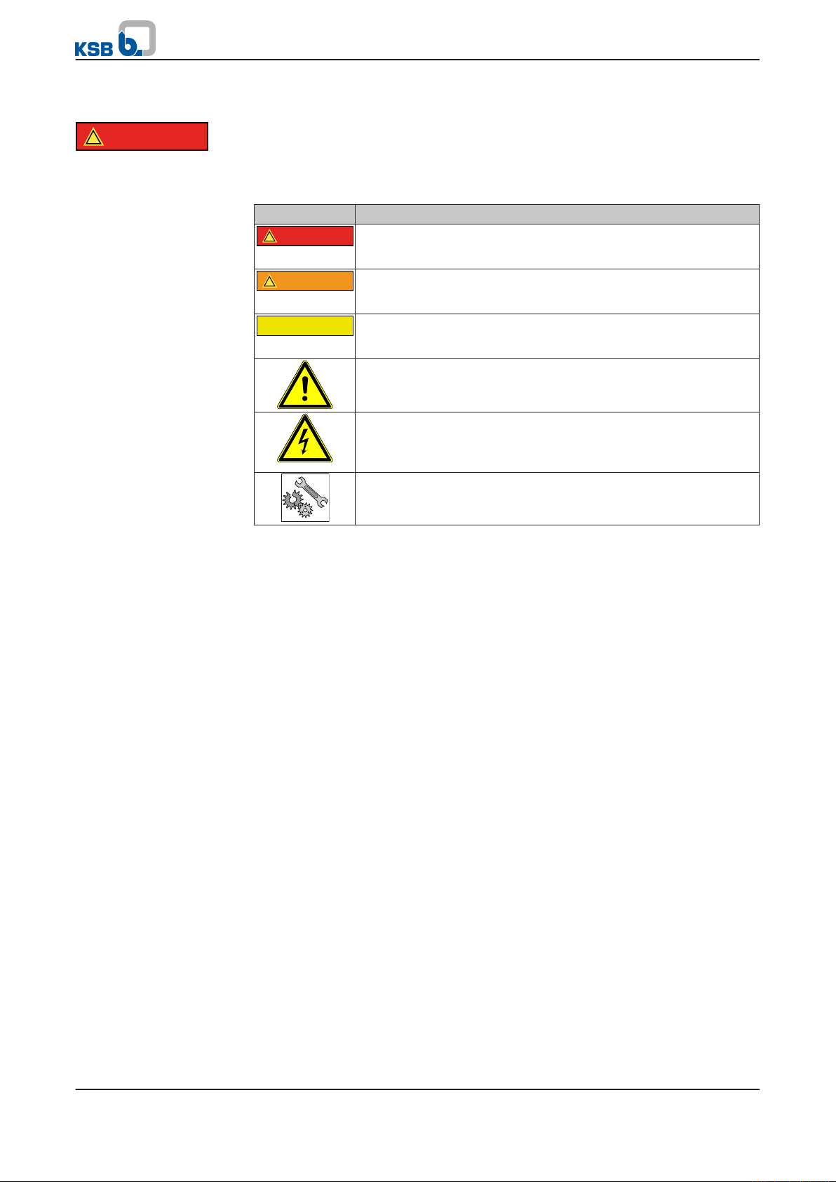
Table 2: Definition of safety symbols/markings
Symbol Description
DANGER
This signal word indicates a high-risk hazard which, if not avoided,
will result in death or serious injury.
WARNING
This signal word indicates a medium-risk hazard which, if not
avoided, could result in death or serious injury.
CAUTION
This signal word indicates a hazard which, if not avoided, could
result in damage to the machine and its functions.
General hazard
In conjunction with one of the signal words this symbol indicates a
hazard which will or could result in death or serious injury.
Electrical hazard
In conjunction with one of the signal words this symbol indicates a
hazard involving electrical voltage and identifies information about
protection against electrical voltage.
Machine damage
In conjunction with the signal word CAUTION this symbol indicates
a hazard for the machine and its functions.
2.2 General
This manual contains general installation, operating and maintenance instructions
that must be observed to ensure safe pump operation and prevent personal injury
and damage to property.
The safety information in all sections of this manual must be complied with.
This manual must be read and completely understood by the specialist personnel/
operators responsible prior to installation and commissioning.
The contents of this manual must be available to the specialist personnel at the site
at all times.
Information attached directly to the pump must always be complied with and be
kept in a perfectly legible condition at all times. This applies to, for example:
▪ Arrow indicating the direction of rotation
▪ Markings for connections
▪ Name plate
The operator is responsible for ensuring compliance with all local regulations not
taken into account in this manual.
2.3 Intended use
▪ The pump (set) must only be operated within the operating limits described in
the other applicable documents.
▪ Only operate pumps/pump sets which are in perfect technical condition.
▪ Do not operate the pump (set) in partially assembled condition.
▪ Only use the pump to handle the fluids described in the data sheet or product
literature of the pump model or variant.
▪ Never operate the pump without the fluid to be handled.
▪ Observe the minimum flow rates indicated in the data sheet or product literature
(to prevent overheating, bearing damage, etc).
Rio-Eco N / Rio-Eco Z N / Rio-Eco Therm N
7 of 36
Page 8

2 Safety
▪ Observe the maximum flow rates indicated in the data sheet or product
literature (to prevent overheating, mechanical seal damage, cavitation damage,
bearing damage, etc).
▪ Do not throttle the flow rate on the suction side of the pump (to prevent
cavitation damage).
▪ Consult the manufacturer about any use or mode of operation not described in
the data sheet or product literature.
Prevention of foreseeable misuse
▪ Never exceed the permissible operating limits specified in the data sheet or
product literature regarding pressure, temperature, etc.
▪ Observe all safety information and instructions in this manual.
2.4 Personnel qualification and training
All personnel involved must be fully qualified to transport, install, operate, maintain
and inspect the machinery this manual refers to.
The responsibilities, competence and supervision of all personnel involved in
transport, installation, operation, maintenance and inspection must be clearly
defined by the operator.
Deficits in knowledge must be rectified by means of training and instruction
provided by sufficiently trained specialist personnel. If required, the operator can
commission the manufacturer/supplier to train the personnel.
Training on the pump (set) must always be supervised by technical specialist
personnel.
2.5 Consequences and risks caused by non-compliance with this manual
▪ Non-compliance with this operating manual will lead to forfeiture of warranty
cover and of any and all rights to claims for damages.
▪ Non-compliance can, for example, have the following consequences:
– Hazards to persons due to electrical, thermal, mechanical and chemical
effects and explosions
– Failure of important product functions
– Failure of prescribed maintenance and servicing practices
– Hazard to the environment due to leakage of hazardous substances
8 of 36
2.6 Safety awareness
In addition to the safety information contained in this manual and the intended use,
the following safety regulations shall be complied with:
▪ Accident prevention, health and safety regulations
▪ Explosion protection regulations
▪ Safety regulations for handling hazardous substances
▪ Applicable standards, directives and laws
2.7 Safety information for the operator/user
▪ The operator shall fit contact guards for hot, cold and moving parts and check
that the guards function properly.
▪ Do not remove any contact guards during operation.
▪ Contain leakages (e.g. at the shaft seal) of hazardous fluids handled (e.g.
explosive, toxic, hot) so as to avoid any danger to persons and the environment.
Adhere to all relevant laws.
▪ Eliminate all electrical hazards. (In this respect refer to the applicable national
safety regulations and/or regulations issued by the local energy supply
companies.)
Rio-Eco N / Rio-Eco Z N / Rio-Eco Therm N
Page 9

2 Safety
▪ If shutting down the pump does not increase potential risk, fit an emergency-
stop control device in the immediate vicinity of the pump (set) during pump set
installation.
2.8 Safety information for maintenance, inspection and installation
▪ Modifications or alterations of the pump are only permitted with the
manufacturer's prior consent.
▪ Use only original spare parts or parts authorised by the manufacturer. The use of
other parts can invalidate any liability of the manufacturer for resulting damage.
▪ The operator ensures that maintenance, inspection and installation is performed
by authorised, qualified specialist personnel who are thoroughly familiar with
the manual.
▪ Only carry out work on the pump (set) during standstill of the pump.
▪ Any work on the pump set shall only be performed when it has been
disconnected from the power supply (de-energised).
▪ The pump casing must have cooled down to ambient temperature.
▪ Pump pressure must have been released and the pump must have been drained.
▪ When taking the pump set out of service always adhere to the procedure
described in the manual. (⇨ Section 6.4 Page 28)
▪ Decontaminate pumps which handle fluids posing a health hazard.
▪ As soon as the work has been completed, re-install and/or re-activate any safety-
relevant and protective devices. Before returning the product to service, observe
all instructions on commissioning. (⇨ Section 6.1 Page 20)
2.9 Unauthorised modes of operation
Never operate the pump (set) outside the limits stated in the data sheet and in this
manual.
The warranty relating to the operating reliability and safety of the supplied pump
(set) is only valid if the equipment is used in accordance with its intended use.
Rio-Eco N / Rio-Eco Z N / Rio-Eco Therm N
9 of 36
Page 10
3 Transport/Temporary Storage/Disposal
3 Transport/Temporary Storage/Disposal
3.1 Checking the condition upon delivery
1. On transfer of goods, check each packaging unit for damage.
2.
In the event of in-transit damage, assess the exact damage, document it and
notify KSB or the supplying dealer (as applicable) and the insurer about the
damage in writing immediately.
3.2 Transport
CAUTION
Improper pump transport
Damage to the pump!
▷ Never suspend the pump/pump set from the power cable.
▷ Prevent the pump (set) from getting knocked or dropped.
3.3 Storage/preservation
If commissioning is to take place some time after delivery, we recommend that the
following measures be taken for pump (set) storage.
CAUTION
Damage during storage by humidity, dirt, or vermin
Corrosion/contamination of the pump (set)!
▷ For outdoor storage cover the packed or unpacked pump (set) and accessories
with waterproof material.
CAUTION
Wet, contaminated or damaged openings and connections
Leakage or damage to the pump!
▷ Clean and cover pump openings and connections as required prior to putting
the pump into storage.
Store the pump (set) in a dry, protected room where the atmospheric humidity is as
constant as possible.
If properly stored indoors, the pump set is protected for a maximum of 12 months.
For storing a pump (set) which has already been operated, observe the instructions in
(⇨ Section 6.4.1 Page 28)
3.4 Return to supplier
1. Drain the pump as per operating instructions. (⇨ Section 7.2 Page 30)
2.
Always flush and clean the pump, particularly if it has been used for handling
noxious, explosive, hot or other hazardous fluids.
3. If the pump set has handled fluids whose residues could lead to corrosion
damage in the presence of atmospheric humidity or could ignite upon contact
with oxygen, the pump set must also be neutralised, and anhydrous inert gas
must be blown through the pump to ensure drying.
4. Always complete and enclose a certificate of decontamination when returning
the pump (set).
Always indicate any safety and decontamination measures taken.
10 of 36
Rio-Eco N / Rio-Eco Z N / Rio-Eco Therm N
Page 11

3 Transport/Temporary Storage/Disposal
3.5 Disposal
WARNING
Fluids, consumables and supplies which are hot and/or pose a health hazard
Hazard to persons and the environment!
▷ Collect and properly dispose of flushing fluid and any residues of the fluid
handled.
▷ Wear safety clothing and a protective mask, if required.
▷ Observe all legal regulations on the disposal of fluids posing a health hazard.
1. Dismantle the pump (set).
Collect greases and other lubricants during dismantling.
2.
Separate and sort the pump materials, e.g. by:
- Metals
- Plastics
- Electronic waste
- Greases and other lubricants
3. Dispose of materials in accordance with local regulations or in another
controlled manner.
Rio-Eco N / Rio-Eco Z N / Rio-Eco Therm N
11 of 36
Page 12

1
8
Made in EU
29134165
Rio-Eco N 40-120
230V
50Hz
Max 2,70A
EEI ≤ 0,27
Class F
PN6/10 / IP 42 / TF110
2
3
4
5
6
7
KSB Aktiengesellschaft
Johann-Klein-Straße 9
67227 Frankenthal
4 Description of the Pump (Set)
4 Description of the Pump (Set)
4.1 General
▪ Non-self-priming in-line pump
Pump for handling clean or aggressive fluids which are neither chemically nor
mechanically aggressive to the pump materials.
4.2 Designation
Example: Rio-Eco Z N 40-120
Table 3: Designation key
Code Description
Rio Type series
Eco High-efficiency pump
Therm Drinking water pump
Z Twin pump
N New generation
40 Nominal diameter of pipe connection
15 = Rp 1/2
25 = Rp 1
30 = Rp 1 1/4
40 to 80 = DN 40 to DN 80
120 Head in m x 10 (example: 120 = 12 m)
-130 Height 130 mm
4.3 Name plate
Fig. 1: Name plate (example)
1 Type series, size 2 Power supply
3 Mains frequency 4 Maximum power input
5 Energy efficiency index 6 Thermal class
7 Maximum operating pressure,
8 Material number
enclosure, temperature class
Key to the series code
Example: 1235-0867
Table 4: Key
12 of 36
Code Description
12 Year 2012
35 Week
0867 Consecutive number
Rio-Eco N / Rio-Eco Z N / Rio-Eco Therm N
Page 13

4 Description of the Pump (Set)
4.4 Design details
Design
▪ Highly efficient, maintenance-free wet rotor pump (glandless)
Drive
▪ Electronically commutated synchronous motor with permanent magnet rotor
▪ 230 V - 50 Hz
▪ IP42 enclosure
▪ Thermal class F
▪ Temperature class TF 110
▪ Variable speed electric drives to EN 61800-3 EMC requirements
▪ Interference emissions EN 61 000-6-3
▪ Interference immunity EN 61 000-6-2
Bearings
▪ Product-lubricated special plain bearing
Connections
▪ Screw-ended or flanged
Operating modes
▪ Automatic mode with variable differential pressure
▪ Open-loop control mode with external 0 - 10 V setpoint signal for speed
▪ Open-loop control mode with manual setpoint input
Automatic functions
▪ Continuous output adjustment depending on the operating mode
▪ Deblocking function
▪ Soft start (slow start)
▪ Full motor protection with integrated trip electronics
Manual functions
▪ Setting the operating mode
▪ Setting the differential pressure setpoint
▪ Setting the speed level
External control functions
▪ Control input "start/stop"
▪ Control input for remote speed adjustment 0-10 V
Signalling and display functions
▪ General fault indication (volt-free changeover contact)
▪ Fault indication, display of error codes
Interfaces
▪ Serial digital Modbus RTU interface for connecting higher-level automation
systems via the RS485 system bus
Twin pump management
▪ Duty/stand-by mode with timer-controlled pump changeover every 24 hours and
automatic changeover in the event of a fault
Rio-Eco N / Rio-Eco Z N / Rio-Eco Therm N
13 of 36
Page 14

1 2
4
5 6
3
4 Description of the Pump (Set)
4.5 Configuration and function
Design
Function
Fig. 2: Sectional drawing of the pump
1 Discharge nozzle 2 Plain bearing
3 Motor 4 Impeller
5 Suction nozzle 6 Motor shaft
The pump is designed with a radial fluid inlet and a radial outlet arranged on the
same axis. The impeller is rigidly connected to the motor shaft.
The motor housing is equipped with a terminal box. Mechanical sealing is not
required as the rotor is completely separate from the stator winding. The rotor is
lubricated and cooled by the fluid handled. The motor housing is made of
aluminium. Most of the internal parts are made of stainless steel. The advanced
lubricating system with high-quality carbon bearings combined with the precisionbalanced impeller ensure very smooth running and a long service life.
The fluid enters the pump via the suction nozzle (5) and is accelerated outward in a
cylindrical flow by the rotating impeller (4), which is driven by the motor shaft (6). In
the flow passage of the pump casing the kinetic energy of the fluid is converted into
pressure energy. The fluid is pumped to the discharge nozzle (1), where it leaves the
pump. The shaft runs in plain bearings (2), which are supported by the motor (3).
4.6 Noise characteristics
Table 5: Noise characteristics [dB A]
Sound pressure level
Rio-Eco (Therm) N 25-100 to 40-140 35 max.
Rio-Eco (Therm) N 50-70 to 80-120 50 max.
4.7 Scope of supply
Depending on the model, the following items are included in the scope of supply:
▪ Pump set
▪ Installation/operating manual
▪ Sealing elements
14 of 36
Rio-Eco N / Rio-Eco Z N / Rio-Eco Therm N
Page 15

4 Description of the Pump (Set)
4.8 Dimensions and weight
For dimensions and weights please refer to the type series booklet of the pump.
Rio-Eco N / Rio-Eco Z N / Rio-Eco Therm N
15 of 36
Page 16

5 Installation at Site
5 Installation at Site
5.1 Safety regulations
DANGER
Installation in potentially explosive atmospheres
Explosion hazard!
▷ Never install the pump in potentially explosive atmospheres.
▷ Observe the information given in the data sheet and on the name plates of the
pump system.
DANGER
Rio-Eco N and Rio-Eco Z N pumps used for drinking water or foodstuff applications
Danger of poisoning!
▷ The pump materials are not suitable for drinking water and foodstuff
applications.
Never use the pump for drinking water or foodstuff applications.
5.2 Checks to be carried out prior to installation
Before installing the pump make sure that the following requirements are met:
▪ Check the data on the name plate of the pump to make sure it can be operated
on the available mains.
▪ The fluid to be handled matches the description of suitable fluids.
▪ The above safety instructions have been complied with.
5.3 Installing the pump set
Install the pump set in an easily accessible place.
CAUTION
Ingress of fluid into the motor
Damage to the pump set!
▷ Install the pump set with the pump shaft in a horizontal position. Connect the
piping without transmitting any stresses and strains.
▷ Never install the pump set with the motor terminal box pointing downwards.
NOTE
Installing shut-off valves upstream and downstream of the pump is recommended.
Make sure that no leaking water can drip into the pump motor or terminal box.
The terminal box can be positioned correctly by turning the motor head.
16 of 36
Rio-Eco N / Rio-Eco Z N / Rio-Eco Therm N
Page 17

5 Installation at Site
Table 6: Permissible installation positions
Sizes
Rio-Eco (Therm) N 30-100, 30-120 32-120,
40-100, 40-120, 50-70, 50-90
Rio-Eco (Therm) N 40-140, 50-140, 65-90,
65-120, 80-120
Rio-Eco Z N
To do so, undo the bolts/screws and turn the motor head until it has reached its
correct position.
Tighten the bolts/screws again.
DANGER
Leakage at the pump
Leakage of hot fluids!
▷ Insert the O-ring in the correct position.
An arrow on the pump casing indicates the direction of flow.
NOTE
The direction of flow of a vertically installed pump should be upwards.
CAUTION
Air entering the pump
Damage to vertically installed pump sets whose direction of flow is downwards!
▷ Fit a vent valve at the highest point of the suction line.
NOTE
To prevent any impurities from collecting in the pump do not install the pump at
the lowest point of the system.
Screw-ended pumps
Flanged pump
1. Place the pump in the specified installation position.
Accurately insert the sealing element.
2.
3. Connect the pump and piping with a pipe union.
4. Tighten the pipe union hand tight with an assembly tool (e.g. pipe wrench).
5. Accurately insert the sealing element in the opposite pipe union.
6. Tighten the pipe union hand tight with an assembly tool (e.g. pipe wrench).
1. Place the pump in the specified installation position.
Rio-Eco N / Rio-Eco Z N / Rio-Eco Therm N
17 of 36
Page 18

5 Installation at Site
2. Accurately insert the sealing element.
Connect the pump flange to the pipe flange by means of screws.
3.
4. Tighten the screws hand-tight with an assembly tool (e.g. wrench).
5. Accurately insert the sealing element on the opposite side.
6. Connect the pump flange to the pipe flange by means of screws. Tighten the
screws hand-tight.
5.4 Connecting the piping
DANGER
Excessive loads acting on the pump nozzles
Danger to life from leakage of hot fluids!
▷ Do not use the pump as an anchorage point for the piping.
▷ Anchor the pipelines in close proximity to the pump and connect them without
transmitting any stresses or strains.
▷ Take appropriate measures to compensate thermal expansion of the piping.
CAUTION
Contamination/dirt in the piping
Damage to the pump!
▷ Flush the piping prior to commissioning or replacing the pump. Remove any
foreign matter.
NOTE
Installing check and shut-off elements in the system is recommended, depending on
the type of plant and pump. However, such elements must not obstruct proper
drainage or hinder disassembly of the pump.
✓ Suction lift lines have been laid with a rising slope, suction head lines with a
downward slope towards the pump.
✓ The nominal diameters of the pipes are equal to or greater than the nominal
diameters of the pump nozzles.
✓ The pipelines have been anchored in close proximity to the pump and
connected without transmitting any stresses or strains.
Thoroughly clean, flush and blow through all vessels, pipelines and connections
1.
(especially of new installations).
18 of 36
CAUTION
Welding beads, scale and other impurities in the piping
Damage to the pump!
▷ Free the piping from any impurities.
5.5 Casing/insulation
WARNING
The pump takes on same temperature as the fluid handled
Risk of burns!
▷ Insulate the volute casing.
▷ Fit protective equipment.
Rio-Eco N / Rio-Eco Z N / Rio-Eco Therm N
Page 19

5 Installation at Site
CAUTION
Heat building up at motor housing and pump casing
Pump overheating!
▷ Never insulate the motor and electronic system housings.
5.6 Electrical connection
DANGER
Electrical connection work by unqualified personnel
Danger of death from electric shock!
▷ Always have the electrical connections installed by a trained and qualified
electrician.
▷ Observe regulations IEC 60364 and, for explosion-proof models, EN 60079.
DANGER
Work performed on an energised terminal box
Danger of death from electric shock!
▷ Switch off the supply voltage at least 5 minutes prior to commencing work and
ensure that it cannot be switched on again unintentionally.
WARNING
Incorrect connection to the mains
Damage to the mains network, short circuit!
▷ Observe the technical specifications of the local energy supply companies.
1. Check the available mains voltage against the data on the name plate.
Select an appropriate start-up method.
2.
NOTE
The cable must be of type H05VV-F 3G1 or similar, with an outside diameter
≥ 7.2 mm. Circuit breaker: 10/16 A (minimal rated current x 1.4) slow blowing fuse
or automatic circuit breaker type C.
NOTE
If the pump set is to be switched off by means of an owner-supplied mains relay,
this relay must meet the following requirements as a minimum: rated
current ≥ 10 A, rated voltage 250 VAC.
NOTE
Connection to the power supply must be effected by means of a fixed power cable
with a minimum cross-section of 3 x 1.5 mm2, which is fitted with a plug-type
connection or an all-pole isolating switch with a minimum contact opening of
3 mm.
Rio-Eco N / Rio-Eco Z N / Rio-Eco Therm N
19 of 36
Page 20

6 Commissioning/Start-up/Shutdown
6 Commissioning/Start-up/Shutdown
6.1 Commissioning/start-up
6.1.1 Prerequisites for commissioning/start-up
Before commissioning/starting up the pump set, make sure that the following
conditions are met:
▪ The pump set has been properly connected to the power supply and is equipped
with all protection devices.
▪ The pump has been primed with the fluid to be handled. The pump has been
vented. (⇨ Section 6.1.2 Page 20)
▪ After prolonged standstill of the pump (set) the pump rotor has been rotated by
means of a screwdriver to make sure the motor is not locked.
6.1.2 Priming and venting the pump
CAUTION
Increased wear due to dry running
Damage to the pump set!
▷ Never operate the pump set without liquid fill.
▷ Never close the shut-off element in the suction line and/or supply line during
pump operation.
1. Vent the pump and suction line and prime both with the fluid to be handled.
2.
Fully open the shut-off element in the suction line.
3. During operation (at top speed) loosen the screw plug until some air escapes.
DANGER
Hot fluid handled spurting out in the vent plug area
Risk of burns!
▷ Wear protective clothing.
4. Close the screw plug again.
5.
Repeat this procedure several times until all air has escaped.
6.1.3 Start-up
DANGER
Non-compliance with the permissible pressure and temperature limits if the pump is
operated with the suction and discharge lines closed.
Leakage of hot fluids!
▷ Never operate the pump with the shut-off elements in the suction line and/or
discharge line closed.
▷ Only start up the pump set against a slightly or completely open discharge-side
shut-off element.
DANGER
Excessive temperatures due to insufficient lubrication of shaft seal
Damage to the pump set!
▷ Never operate the pump set without liquid fill.
▷ Prime the pump as per operating instructions.
▷ Always operate the pump within the permissible operating range.
20 of 36
Rio-Eco N / Rio-Eco Z N / Rio-Eco Therm N
Page 21

6 Commissioning/Start-up/Shutdown
CAUTION
Abnormal noises, vibrations, temperatures or leakage
Damage to the pump!
▷ Switch off the pump (set) immediately.
▷ Eliminate the causes before returning the pump set to service.
✓ The system piping has been cleaned.
✓ Pump, suction line and inlet tank, if any, have been vented and primed with the
fluid to be pumped.
✓ The lines for priming and venting have been closed.
Fully open the shut-off element in the suction head/suction lift line.
1.
2. Close or slightly open the shut-off element in the discharge line.
3. Start up the motor.
Rio-Eco N / Rio-Eco Z N / Rio-Eco Therm N
21 of 36
Page 22

2
1
ON
OFF
RUN
0V IN
H
Q
A
H
Q
H
Q
6 Commissioning/Start-up/Shutdown
6.1.4 Mode of operation
6.1.4.1 Automatic control
The closed-loop control mode integrated in the pump is active when the operating
mode is set to
Internal
DIP switch 1 = ON Operating mode
DIP switch 1 = OFF Operating mode
. The operating mode can be set at DIP switch 1.
External
Internal
Fig. 3: DIP switch (example: single pump in Internal mode)
The pump starts up when the terminal pair RUN is bridged (factory setting) and stops
when the terminal pair is not bridged.
Fig. 4: Terminal pair RUN
The pump is operated within the control curve for maximum pump power output
P
= Q x H (point A, dashed line) and automatically adjusts itself to different output
max
requirements. The control knob is set to its middle position (see illustration).
22 of 36
By turning the control knob at the control module the pump power output can be
adjusted manually. By turning the control knob anti-clockwise the pump power
output can be reduced, e.g. in case of flow noises. This means the control curve will
shift towards lower heads.
By turning the control knob clockwise the pump power output can be increased, e.g.
if some radiators remain cold despite hydraulic input. This means the control curve
will shift towards higher heads.
Control mode function
Closing of thermostatic valves (or similar control devices) reduces the volume flow
rate to be pumped, which also decreases the friction loss in the piping. The pump
control system recognises this event and reduces the pump input power. As the
volume flow rate decreases, the head decreases correspondingly. This ensures smooth
and trouble-free running of the pump at minimised power input.
Rio-Eco N / Rio-Eco Z N / Rio-Eco Therm N
Page 23

2
1
ON
OFF
RUN
0V IN
H
Q
1
2 3 4
2
1
ON
OFF
RUN
0V IN
6 Commissioning/Start-up/Shutdown
6.1.4.2 Open-loop control:
The closed-loop control mode integrated in the pump is active when the operating
mode is set to
Internal
DIP switch 1 = ON Operating mode
DIP switch 1 = OFF Operating mode
Fig. 5: DIP switch (example: single pump in
. The operating mode can be set at DIP switch 1.
External
Internal
Internal
mode)
The pump starts up when the terminal pair RUN is bridged (factory setting) and stops
when the terminal pair is not bridged.
Fig. 6: Terminal pair RUN
The pump is operated at the set speed level (characteristic curve). The speed can be
set to up to four different levels.
In the example (see illustration) the pump is operated at speed level 1. The required
speed level is selected by turning the control knob at the control module.
6.1.4.3 Open-loop control mode with external setpoint 0 - 10 V
The external open-loop control mode via analog signal 0-10 VDC is active when the
operating mode is set to
External
.
The operating mode can be set at DIP switch 1.
DIP switch 1 = ON Operating mode
DIP switch 1 = OFF Operating mode
External
Internal
Fig. 7: DIP switch (example: single pump in "External" mode)
The external analog signal is wired to the terminal pair (OV / IN) integrated in the
pump. The pump starts up when the terminal pair RUN is bridged (factory setting)
and stops when the terminal pair is not bridged.
Fig. 8: Terminal pair OV / IN and RUN
Rio-Eco N / Rio-Eco Z N / Rio-Eco Therm N
23 of 36
Page 24

n [min-1]
U [V]
10 V
0 V
n
max
0
2
1
ON
OFF
6 Commissioning/Start-up/Shutdown
The pump is operated in open-loop control mode depending on the external analog
speed signal (0-10 VDC) (setpoint) (0 VDC = minimum speed / 10 VDC = maximum
speed).
Fig. 9: Interdependence between the speed setpoint and the external input signal
6.1.4.4 Operation via Modbus
The pumps Rio-Eco N 25-100, 30-100 to 80-120 come with a Modbus interface
integrated in the control module. The Modbus interface (plug-type connection) is
located on the bottom of the control module. It is closed with a protective cap
(IP 42).
The Modbus operating mode is assigned top priority and is always active regardless
of the position of DIP switch 1. Active Modbus settings can be deactivated by
changing the position DIP switch 1 once. The internal pump control will then take
over controlling the pump. To return to the Modbus operating mode, the Modbus
input must be re-activated in the control station.
All Modbus data points (variables) can be read at all times (monitoring). If the
Modbus setting is activated the control module will not react to any external analog
signal which may be connected. Internal pump control with automatic or manual
output adjustment is deactivated.
For connecting the pump to a Modbus network connect the Modbus data cable,
which is available as an accessory (19075536), to the plug integrated in the control
module and to the Modbus.
Table 7: Technical data of the Modbus interface
Parameters Description/value
Terminal cross-section 1.5 mm
2
Interface RS485 (TIA-485A) optically isolated
Bus connection Shielded bus cable, twisted in pairs, 1x 2x 0.5 mm
2
Cable length 1000 m maximum, stub lines impermissible
Wave impedance 120 ohm (cable type B to TIA 485-A)
Data rate [baud] 2,400
9,600 (factory setting)
19,200
Protocol Modbus RTU (see Modbus installation/operating
manual)
Data format 8 data bits,
no parity, 1 stop bit
24 of 36
6.1.4.5 Operating mode single pump
The single pump operating mode can be set at DIP switch 2.
DIP switch 2 = ON Twin pump
DIP switch 2 = OFF Single pump
Fig. 10: DIP switch (example: single pump operating mode and control integrated in
the pump)
Rio-Eco N / Rio-Eco Z N / Rio-Eco Therm N
Page 25

2
1
ON
OFF
2
1
ON
OFF
6 Commissioning/Start-up/Shutdown
6.1.4.6 Operating mode twin pump
DIP switch 2 = ON Twin pump
DIP switch 2 = OFF Single pump
Fig. 11: DIP switch (example: twin pump operating mode and control integrated in
the pump)
The control modules of both pumps are connected with the data cable which is
contained in the scope of supply of the Rio-Eco Z N pump (also see accessories). The
terminals of the terminal pair RUN must be bridged at both pumps.
The data cable is connected to the two COM ports of the control modules, which are
also used for connecting the Modbus. This means that pumps in twin pump
operating mode cannot be connected to a higher-level automation system via
Modbus.
Function
The twin pump operating mode is activated when both pumps are started up. The
duty/stand-by operating mode becomes active after a few seconds and will stop one
of the pumps. The pump which remains active (on duty) is operated at 0 - 100 %; the
other pump will be on stand-by. The red LED of the stand-by pump will light up and
the function "external start/stop" will be deactivated for the stand-by pump,
irrespective of the wiring of the terminal pair RUN. The duty pump can be controlled
by means of the integrated functions "open loop control with external setpoint
0-10 VDC" and/or "external start/stop".
NOTE
The two pumps can be parameterised differently.
Each pump is operated in accordance with its settings. For example, one pump could
be operated in closed-loop control and the other in open-loop control. To ensure
that the changeover from duty pump to stand-by pump will not have any impact on
the operation regarding duty point and operating mode, the parameter settings of
both pumps must be identical.
The two functions (1) and (2) will be carried out automatically.
Automatic pump changeover (1)
The pumps come with an integrated timer, which switches off the duty pump after
24 hours of operation and starts up the stand-by pump. To this effect, two minutes
before the duty pump is switched off it signals a start command to the stand-by
pump. The stand-by pump will be started up and the first pump will be switched off.
Redundant operation (2)
In the event of a failure of the duty pump the stand-by pump will be started up
automatically to take over the function of the failed pump.
6.1.4.7 Operating mode dual pump
DIP switch 2 = ON Dual pump
DIP switch 2 = OFF Single pump
Fig. 12: DIP switch (example: Dual-pump Operation operating mode and control
system integrated in the pump)
Rio-Eco N / Rio-Eco Z N / Rio-Eco Therm N
25 of 36
Page 26

RUN
0V IN
NO
NC
COM
RELAY
6 Commissioning/Start-up/Shutdown
Two individual pumps of the same performance data can be controlled and operated
individually by an automation system via Modbus. In this case, the automation system
will control the operating mode and the operating status of each pump separately.
The two pumps must be connected to the automation system with the Modbus
connection cable, which is available as an option (see accessories).
6.1.4.8 External start/stop
The pump is started up/stopped as a function of a volt-free external signal.
The external signal is wired to the terminal pair RUN integrated in the pump. The
pump is switched off when the connected cable is separated from the terminals and
the red LED flashes. (⇨ Section 9.2 Page 33) .
Fig. 13: Terminal pair RUN
6.1.4.9 Alerts
The relay with volt-free NC and NO contact, which is integrated in the pump, will
react if the control module is defective. (⇨ Section 9.2 Page 33) .
The signal is wired to the terminal pair NO/NC/COM.
Fig. 14: Terminal pair NO/NC/COM
Acknowledging an alert
Disconnect the pump from the power supply.
1.
2. Re-connect the pump to the power supply.
6.1.4.10 Displays
The operating status of the pump is signalled by two LEDs at the control module of
the pump.
Table 8: Description of the LED signal
LED signal Operating status of pump
No display Pump switched off, not energised
Green Pump started up, failure-free operation
Red (permanent) Failure of the electronics
Red (flashing) Start/stop function interrupted
The red LED signals the type of failure by different flashing frequencies. The error
code is repeated every minute, approximately.
26 of 36
Rio-Eco N / Rio-Eco Z N / Rio-Eco Therm N
Page 27

Number of
flashes
2
3
4
5
6
1
1 2 3 4 5 6
1 2 3 4 5
1 2 3 4
1 2 3
1 2
1
150 150 150 150 150 150 150 150 150 150 150 150 Time in ms
Total time 2100 ms
6 Commissioning/Start-up/Shutdown
Table 9: Display of error codes
Flashing frequency
Cause of failure
1)
1 - pause - 1 Excessive electronics temperature
2 - pause - 2 Excessive motor temperature
3 - pause - 3 Motor is overloaded
4 - pause - 4 Pump is overloaded
5 - pause - 5 Internal control error
6 - pause - 6 Supplied voltage too high / too low
Fig. 15: Duration and frequency of flashing light
Trouble-shooting (⇨ Section 8 Page 32)
6.2 Shutdown
✓ The shut-off element in the suction line is and remains open.
1.
Close the shut-off element in the discharge line.
2. Switch off the motor and make sure the pump set runs down smoothly to a
standstill.
NOTE
If the discharge line is equipped with a check valve, the shut-off element in the
discharge line may remain open, provided the site's requirements and regulations
are taken into account and observed.
For prolonged shutdown periods:
Close the shut-off element in the suction line.
1.
CAUTION
Risk of freezing during prolonged pump shutdown periods
Damage to the pump!
▷ Drain the pump and the cooling/heating chambers (if any) or otherwise protect
them against freezing.
1)
The pump tries to continue its operation regardless of any failure messages.
Rio-Eco N / Rio-Eco Z N / Rio-Eco Therm N
27 of 36
Page 28

6 Commissioning/Start-up/Shutdown
6.3 Operating limits
DANGER
Non-compliance with operating limits for pressure, temperature, fluid handled and
speed
Hot fluid may escape!
▷ Comply with the operating data indicated in the data sheet.
▷ Avoid prolonged operation against a closed shut-off element.
▷ Never operate the pump at product temperatures exceeding those specified in
the data sheet or on the name plate.
6.3.1 Ambient temperature
CAUTION
Operation outside the permissible ambient temperature
Damage to the pump (set)!
▷ Observe the specified limits for permissible ambient temperatures.
Observe the following parameters and values during operation:
Table 10: Temperature of the fluid handled as a function of the ambient temperature
[°C]
Temperature of the fluid
Ambient temperature
handled
Rio-Eco (Therm) N 25-100,
30-100, 30-120, 32-120,
110 30
90 40
40-100, 40-120, 40-140,
50-70, 50-90, 50-140
Rio-Eco N 65-90, 65-120 to
80-120
90 30
70 40
6.3.2 Density of the fluid handled
The pump input power changes in proportion to the density of the fluid handled.
CAUTION
Impermissibly high density of the fluid handled
Motor overload!
▷ Observe the information on fluid density in the data sheet.
6.4 Shutdown/storage/preservation
6.4.1 Measures to be taken for shutdown
The pump (set) remains installed
✓ Sufficient fluid is supplied for the operation check run of the pump.
1.
Start up the pump (set) regularly between once a month and once every three
months for approximately five minutes during prolonged shutdown periods.
This will prevent the formation of deposits within the pump and the pump
intake area.
The pump is removed from the pipe and stored
The pump has been properly drained (⇨ Section 7.2 Page 30) and the safety
instructions for dismantling the pump have been observed.
Observe any additional instructions and information provided. (⇨ Section 3 Page 10)
28 of 36
Rio-Eco N / Rio-Eco Z N / Rio-Eco Therm N
Page 29

6 Commissioning/Start-up/Shutdown
6.5 Returning to service
For returning the pump to service observe the sections on commissioning/start-up
and the operating limits.
In addition, carry out all servicing/maintenance operations before returning the
pump (set) to service.
WARNING
Failure to re-install or re-activate protective devices
Risk of injuries by escaping fluid!
▷ As soon as the work is completed, re-install and/or re-activate any safety-
relevant and protective devices.
Also see
● Electrical connection, overview of settings, LED displays [⇨ 33]
Rio-Eco N / Rio-Eco Z N / Rio-Eco Therm N
29 of 36
Page 30

7 Servicing/Maintenance
7 Servicing/Maintenance
7.1 Servicing/inspection
The circulator pumps are almost maintenance-free.
If the pump has not been in operation for a prolonged period of time or if the
system is severely contaminated, the rotor can become blocked.
The rotor can be deblocked by undoing the screwed plug, inserting a screw driver
into the shaft end, and rotating the rotor.
NOTE
Any repairs on the pump must only be performed by one of our authorised service
partners.
In the event of a failure, please contact your heating system engineer.
7.2 Drainage/cleaning
WARNING
Fluids, consumables and supplies which are hot and/or pose a health hazard
Hazard to persons and the environment!
▷ Collect and properly dispose of flushing fluid and any residues of the fluid
handled.
▷ Wear safety clothing and a protective mask, if required.
▷ Observe all legal regulations on the disposal of fluids posing a health hazard.
1. Always flush the pump if it has been used for handling noxious, hot or other
hazardous fluids.
Always flush and clean the pump before transporting it to the workshop.
Provide a cleaning record for the pump.
7.3 Removing the pump set from the piping
7.3.1 Dismantling the complete pump set
DANGER
Work performed on an energised terminal box
Danger of death from electric shock!
▷ Switch off the supply voltage at least 5 minutes prior to commencing work and
ensure that it cannot be switched on again unintentionally.
DANGER
Strong magnetic field in the rotor area
Danger of death for persons with pacemaker!
▷ Keep a safety distance of at least 0.3 m.
DANGER
Pump acting as a generator when running in reverse
Danger to life from hazardous induction voltage at the motor terminals!
▷ Prevent the fluid from flowing back by closing the shut-off elements.
30 of 36
Rio-Eco N / Rio-Eco Z N / Rio-Eco Therm N
Page 31

7 Servicing/Maintenance
WARNING
Danger by strong magnetic field
Danger of crushing injuries when pulling out the rotor!
Due to the strong magnetic field the rotor can be suddenly pulled back into its
original position!
Danger of magnetic parts near the rotor being attracted!
▷ The rotor must generally only be removed from the motor housing by
authorised specialist personnel.
▷ Remove any magnetic parts from the vicinity of the rotor.
▷ Keep the assembly area clean.
▷ Keep a safety distance of at least 0.3 m from electronic components.
CAUTION
Strong magnetic field in the rotor area
Interference with magnetic data carriers, electronic devices, components and
instruments!
Uncontrolled magnetic attraction forces between magnetic components, tools or
similar!
▷ Remove any magnetic parts from the vicinity of the rotor.
▷ Keep the assembly area clean.
CAUTION
Danger by strong magnetic field
Negative impact on or damage to electrical devices!
▷ The rotor must generally only be removed from the motor housing by
authorised specialist personnel.
✓ The relevant notes and steps stated have been observed/carried out.
✓ The pump has cooled down to ambient temperature.
✓ A container for collecting the fluid has been positioned underneath the pump
set.
1. De-energise the pump set (disconnect the motor) and ensure that it cannot be
re-energised unintentionally.
2. Close the shut-off elements.
3. Disconnect the discharge and suction nozzles from the piping.
4. Depending on the pump/motor size, remove the supports from the pump set.
5. Remove the complete pump set from the piping.
Rio-Eco N / Rio-Eco Z N / Rio-Eco Therm N
31 of 36
Page 32

8 Trouble-shooting
8 Trouble-shooting
WARNING
Improper work to remedy faults
Risk of injury!
▷ For any work to remedy faults observe the relevant information in this manual
or in the relevant accessory manufacturer's product literature.
Table 11: Trouble-shooting
A B C D E F G H Possible cause
✘ - - - - - - - Master switch OFF, defective fuse, earth
- ✘ - - - - - - Remote start/stop contact has been
- - ✘ - - - - - Temperature of electronics increased for a
- - - ✘ - - - - Temperature of the motor increased for a
- - - - ✘ - - - Pump overloaded for a short time Check whether the impeller is polluted.
- - - - - ✘ - - Pump overloaded Check whether the impeller is polluted.
- - - - - - ✘ - Internal control error Contact KSB Service.
- - - - - - - ✘ Overvoltage of supply network (exceeding
If problems occur that are not described in the following table, consultation with the
KSB customer service is required.
Pump not running — no LED display
A
Pump starts up but stops again immediately
B
Pump not running — LED display flashes 1x - pauses - flashes 1x
C
Pump not running — LED display flashes 2x - pauses - flashes 2x
D
Pump not running — LED display flashes 3x - pauses - flashes 3x
E
Pump running irregularly — LED display flashes 4x - pauses - flashes 4x
F
Pump not running — LED display flashes 5x - pauses - flashes 5x
G
Pump not running — LED display flashes 6x - pauses - flashes 6x
H
Remedy
2)
Check master switch and fuse. Check the
conductor not or incorrectly connected
pump connection.
Fit connecting bridge for start/stop
removed
function.
Verify that the water and ambient
short time
temperature are within the indicated
temperature ranges.
Verify that the water and ambient
short time
temperature are within the indicated
temperature ranges.
Check that the pump is connected properly
the tolerance)
and verify the operating voltage against
the data on the name plate.
2)
Pump pressure must be released before attempting to remedy faults on parts which are subjected to pressure.
32 of 36
Rio-Eco N / Rio-Eco Z N / Rio-Eco Therm N
Page 33

102
230
81-59 818 814817
310
81-22
L N
Power
NO
1 2
3
4
1
2
9 Related Documents
9 Related Documents
9.1 Sectional drawing with list of components
Part No. Description Part No. Description
102 Volute casing 230 Impeller
310 Plain bearing 81-22 Terminal box cover
81-59 Stator 814 Copper windings
817 Can 818 Rotor
9.2 Electrical connection, overview of settings, LED displays
Fig. 16: Overview
1 Electrical connection 2 Setting for operation
3 LED red = alert 4 LED green = ready for operation
Rio-Eco N / Rio-Eco Z N / Rio-Eco Therm N
33 of 36
Page 34

10 EU Declaration of Conformity
10 EU Declaration of Conformity
Manufacturer: KSB Aktiengesellschaft
Johann-Klein-Straße 9
67227 Frankenthal (Germany)
The manufacturer herewith declares that the product:
Rio-Eco N, Rio-Eco Z N, Rio-Eco Therm N
Series code range: 1616 to 1752
▪ is in conformity with the provisions of the following Directives as amended from time to time:
–
Pump set: EC Machinery Directive 2006/42/EC
– Pump set: Electromagnetic Compatibility Directive 2014/30/EU
– Pump set: Ecodesign Directive 2009/125/EC, Regulations No. 641/2009 and 622/2012
The manufacturer also declares that
▪ the following harmonised international standards have been applied:
–
EN 809
– EN 60335-1, EN 60335-2-51
– EN 61800-3
– EN 16297-1, EN 16297-2
Person authorised to compile the technical file:
Christopher Hamkins
Head of Productionalisation
KSB Aktiengesellschaft
Johann-Klein-Straße 9
67227 Frankenthal (Germany)
The EU Declaration of Conformity was issued in/on:
Frankenthal, 20 April 2016
34 of 36
Joachim Schullerer
Head of Product Development Pump Systems and Drives
KSB Aktiengesellschaft
Johann-Klein-Straße 9
67227 Frankenthal
Rio-Eco N / Rio-Eco Z N / Rio-Eco Therm N
Page 35

Index
Index
A
Applications 7
Automatic functions 13
B
Bearings 13
C
Commissioning 20
Connections 13
D
Design 13
Designation 12
Disposal 11
Drive 13
E
External control functions 13
F
Faults
Causes and remedies 32
Fluid handled
Density 28
I
Intended use 7
Interfaces 13
M
Manual functions 13
Misuse 8
N
Name plate 12
O
Operating limits 28
Operating modes 13
P
Piping 18
Preservation 10, 28
Product description 12
R
Return to supplier 10
Returning to service 29
S
Safety 7
Safety awareness 8
Scope of supply 14
Shutdown 28
Signalling and display functions 13
Start-up 21
Storage 10, 28
Rio-Eco N / Rio-Eco Z N / Rio-Eco Therm N
35 of 36
Page 36

KSB Aktiengesellschaft
67225 Frankenthal • Johann-Klein-Str. 9 • 67227 Frankenthal (Germany)
Tel. +49 6233 86-0 • Fax +49 6233 86-3401
www.ksb.com
1140.82/04-EN
 Loading...