

Page 1
Self-cooling Motor-independent
Frequency Inverter
PumpDrive 2
Installation/Operating Manual
Page 2

Legal information/Copyright
Installation/Operating Manual PumpDrive 2
Original operating manual
All rights reserved. The contents provided herein must neither be distributed, copied, reproduced,
edited or processed for any other purpose, nor otherwise transmitted, published or made available to a
third party without the manufacturer's express written consent.
Subject to technical modification without prior notice.
© KSB Aktiengesellschaft, Frankenthal 21/08/2017
Page 3

Contents
3 of 212
PumpDrive 2
Contents
Glossary .................................................................................................................................................. 5
1 Safety...................................................................................................................................................... 6
1.1 Key to safety symbols/markings.......................................................................................................................6
1.2 General..............................................................................................................................................................6
1.3 Intended use .....................................................................................................................................................6
1.4 Personnel qualification and training...............................................................................................................7
1.5 Consequences and risks caused by non-compliance with this operating manual........................................ 7
1.6 Safety awareness ..............................................................................................................................................7
1.7 Safety information for the user/operator.......................................................................................................7
1.8 Safety information for maintenance, inspection and installation ................................................................7
1.9 Unauthorised modes of operation..................................................................................................................8
1.10 Software Changes.............................................................................................................................................8
1.11 Electromagnetic compatibility (EMC)..............................................................................................................8
1.11.1 Interference emission requirements ...................................................................................................8
1.11.2 Line harmonics requirements..............................................................................................................9
1.11.3 Interference immunity requirements .................................................................................................9
2 Transport/Temporary Storage/Disposal............................................................................................. 10
2.1 Checking the condition upon delivery..........................................................................................................10
2.2 Transport.........................................................................................................................................................10
2.3 Storage............................................................................................................................................................11
2.4 Disposal/recycling ...........................................................................................................................................12
3 General.................................................................................................................................................. 13
3.1 Principles .........................................................................................................................................................13
3.2 Target group...................................................................................................................................................13
3.3 Other applicable documents..........................................................................................................................13
3.4 Symbols ...........................................................................................................................................................13
4 Operation.............................................................................................................................................. 14
4.1 Graphical control panel..................................................................................................................................14
4.1.1 Graphical display................................................................................................................................ 14
4.1.2 Menu keys ..........................................................................................................................................16
4.1.3 Service interface and LED traffic light function...............................................................................21
5 Commissioning report ......................................................................................................................... 23
6 Description............................................................................................................................................ 24
6.1 General description ........................................................................................................................................24
6.2 Designation.....................................................................................................................................................24
6.3 Name plate......................................................................................................................................................26
6.4 Power range and sizes....................................................................................................................................26
6.5 Technical data.................................................................................................................................................27
6.6 Dimensions and weights ................................................................................................................................30
6.7 Mounting options...........................................................................................................................................31
7 Installation at Site................................................................................................................................ 32
7.1 Safety regulations...........................................................................................................................................32
7.2 Checks to be carried out prior to installation...............................................................................................32
7.3 Mounting PumpDrive.....................................................................................................................................32
7.3.1 Motor mounting ................................................................................................................................ 32
7.3.2 Wall/control cabinet mounting.........................................................................................................32
7.4 Electrical connection ......................................................................................................................................33
7.4.1 Safety regulations ..............................................................................................................................33
7.4.2 Information for planning the system ...............................................................................................34
7.4.3 Electrical connection.......................................................................................................................... 38
8 Commissioning/Shutdown.................................................................................................................. 64
8.1 Commissioning wizard ...................................................................................................................................64
Page 4

Contents
4 of 212
PumpDrive 2
8.2 Control point concept ....................................................................................................................................65
8.3 Setting motor parameters..............................................................................................................................65
8.4 Motor control method ...................................................................................................................................66
8.5 Automatic motor adaptation (AMA) of frequency inverter........................................................................67
8.5.1 Automatic motor adaptation (AMA) of frequency inverter for asynchronous motors.................68
8.5.2 Automatic motor adaptation (AMA) of frequency inverter for KSB SuPremE motors .................69
8.6 Entering the setpoint .....................................................................................................................................70
8.7 Pump operation..............................................................................................................................................72
8.7.1 Single-pump operation......................................................................................................................72
8.7.2 Multiple pump configuration ...........................................................................................................82
8.8 Application functions.....................................................................................................................................87
8.8.1 Aligning the frequency inverter with the pump .............................................................................87
8.8.2 Protective functions ...........................................................................................................................89
8.8.3 Flow rate estimation.......................................................................................................................... 96
8.8.4 Energy optimisation...........................................................................................................................98
8.8.5 Ramps ...............................................................................................................................................109
8.8.6 Motor standstill heater.................................................................................................................... 112
8.9 Device functions ...........................................................................................................................................112
8.9.1 Factory and user settings................................................................................................................. 112
8.9.2 Read out PumpMeter ......................................................................................................................113
8.9.3 Date and time ..................................................................................................................................114
8.10 Digital and analog inputs/Digital and analog outputs ..............................................................................114
8.10.1 Digital inputs.................................................................................................................................... 114
8.10.2 Analog inputs................................................................................................................................... 118
8.10.3 Relay outputs ...................................................................................................................................120
8.10.4 Analog outputs ................................................................................................................................ 122
8.10.5 Inputs and outputs of the I/O extension board .............................................................................123
8.11 Parameterising the M12 module.................................................................................................................127
8.12 Parameterising the field bus module..........................................................................................................130
9 Servicing/Maintenance...................................................................................................................... 133
9.1 Safety regulations.........................................................................................................................................133
9.2 Servicing/inspection......................................................................................................................................133
9.2.1 Supervision of operation .................................................................................................................133
9.3 Dismantling...................................................................................................................................................134
9.3.1 Preparing frequency inverter for dismantling ............................................................................... 134
10 Parameter List..................................................................................................................................... 135
10.1 Selection lists.................................................................................................................................................188
11 Trouble-shooting................................................................................................................................ 189
11.1 Faults/malfunctions: Trouble-shooting .......................................................................................................189
11.2 Alerts .............................................................................................................................................................190
11.3 Warnings.......................................................................................................................................................193
11.4 Information messages ..................................................................................................................................195
12 Purchase Order Specifications........................................................................................................... 196
12.1 Ordering spare parts ....................................................................................................................................196
12.2 Accessories ....................................................................................................................................................197
12.2.1 Service software ...............................................................................................................................197
12.2.2 Control panels ..................................................................................................................................197
12.2.3 Motor adapter kits........................................................................................................................... 197
12.2.4 Adapter for wall and cabinet mounting ........................................................................................ 199
12.2.5 M12 module ..................................................................................................................................... 199
12.2.6 Installation options ..........................................................................................................................200
12.2.7 Sensor system ................................................................................................................................... 202
12.2.8 Control cabinet mounting...............................................................................................................205
13 EU Declaration of Conformity........................................................................................................... 207
Index ................................................................................................................................................... 208
Page 5

Glossary
5 of 212
PumpDrive 2
Glossary
Braking resistor
Takes up the braking power produced during
generator operation.
Hydraulic blockage
Undesirable operating situation in which the
pump cannot supply fluid due to a closed inlet or
outlet.
KSB device bus
Proprietary CAN bus that is used in dual and
multiple pump configurations for facilitating
communication among the frequency inverters.
The KSB device bus cannot be used for external
communication or for communication with the
KSB local bus (PumpDrive 1).
Pump
Machine without drive, additional components or
accessories
Pump set
Complete pump set consisting of pump, drive,
additional components and accessories
RCD
Abbreviation for "residual current device"
Page 6
1 Safety
6 of 212
PumpDrive 2
1 Safety
!
DANGER
All the information contained in this section refers to hazardous situations.
1.1 Key to safety symbols/markings
Table1: Definition of safety symbols/markings
Symbol Description
!
DANGER
DANGER
This signal word indicates a high-risk hazard which, if not avoided,
will result in death or serious injury.
!
WARNING
WARNING
This signal word indicates a medium-risk hazard which, if not
avoided, could result in death or serious injury.
CAUTION
CAUTION
This signal word indicates a hazard which, if not avoided, could
result in damage to the machine and its functions.
General hazard
In conjunction with one of the signal words this symbol indicates a
hazard which will or could result in death or serious injury.
Electrical hazard
In conjunction with one of the signal words this symbol indicates a
hazard involving electrical voltage and identifies information about
protection against electrical voltage.
Machine damage
In conjunction with the signal word CAUTION this symbol indicates
a hazard for the machine and its functions.
1.2 General
This operating manual contains general installation, operating and maintenance
instructions that must be observed to ensure safe operation of the system and
prevent personal injury and damage to property.
The safety information in all sections of this manual must be complied with.
The operating manual must be read and understood by the responsible specialist
personnel/operators prior to installation and commissioning.
The contents of this operating manual must be available to the specialist personnel
at the site at all times.
Information attached directly to the product must always be complied with and kept
in a perfectly legible condition at all times. This applies to, for example:
▪ Markings for connections
▪ Name plate
The operator is responsible for ensuring compliance with all local regulations not
taken into account in this operating manual.
1.3 Intended use
▪ This product must only be operated within the limit values stated in the technical
product literature for the mains voltage, mains frequency, ambient temperature,
motor rating, fluid handled, flow rate, speed, density, pressure, temperature and
in compliance with any other instructions provided in the operating manual or
other applicable documents.
▪ The product must not be used in potentially explosive atmospheres.
Page 7

1 Safety
7 of 212
PumpDrive 2
1.4 Personnel qualification and training
All personnel involved must be fully qualified to transport, install, operate, maintain
and inspect the product this manual refers to. The responsibilities, competence and
supervision of all personnel involved in installation, operation, maintenance and
inspection must be clearly defined by the operator.
Deficits in knowledge must be rectified by means of training and instruction
provided by sufficiently trained specialist personnel. If required, the operator can
commission the manufacturer/supplier to train the personnel.
Training on the product must always be supervised by specialist technical personnel.
1.5 Consequences and risks caused by non-compliance with this operating
manual
▪ Non-compliance with this operating manual will lead to forfeiture of warranty
cover and of any and all rights to claims for damages.
▪ Non-compliance can, for example, have the following consequences:
– Hazards to persons due to electrical, thermal, mechanical and chemical
effects and explosions
– Failure of important product functions
– Failure of prescribed maintenance and servicing practices
1.6 Safety awareness
In addition to the safety information contained in this manual and the intended use,
the following safety regulations shall be complied with:
▪ Accident prevention, health and safety regulations
▪ Explosion protection regulations
▪ Safety regulations for handling hazardous substances
▪ Applicable standards, directives and legislation (e.g. EN50110-1)
1.7 Safety information for the user/operator
▪ The operator shall fit contact guards for hot, cold and moving parts and check
that the guards function properly.
▪ Do not remove any contact guards during operation.
▪ Provide the personnel with protective equipment and make sure it is used.
▪ Eliminate all electrical hazards. (In this respect refer to the applicable national
safety regulations and/or regulations issued by the local energy supply
companies.)
1.8 Safety information for maintenance, inspection and installation
▪ Modifications or alterations of the pump are only permitted with the
manufacturer's prior consent.
▪ Use only original spare parts or parts authorised by the manufacturer. The use of
other parts can invalidate any liability of the manufacturer for resulting damage.
▪ The operator ensures that maintenance, inspection and installation is performed
by authorised, qualified specialist personnel who are thoroughly familiar with
the manual.
▪ Any work on the product shall only be performed when it has been disconnected
from the power supply (de-energised).
▪ Carry out work on the product during standstill only.
▪ As soon as the work has been completed, re-install and re-activate any safety-
relevant devices and protective devices. Before returning the product to service,
observe all instructions on commissioning.
Page 8

1 Safety
8 of 212
PumpDrive 2
1.9 Unauthorised modes of operation
Never operate the product outside the limits stated in the data sheet and in this
manual.
The warranty relating to the operating reliability and safety of the product supplied
is only valid if the product is used in accordance with its intended use.
1.10 Software Changes
The software has been specially created for this product and thoroughly tested.
It is impermissible to make any changes or additions to the software or parts of the
software. Software updates supplied by KSB are excluded from this rule.
1.11 Electromagnetic compatibility (EMC)
The Electromagnetic Compatibility Directive 2004/108/EC defines the requirements
concerning the interference immunity and interference emissions of electric and
electronic equipment.
1.11.1 Interference emission requirements
The EN61800-3 EMC product standard is relevant for electric variable speed drives/
control systems. It specifies all pertinent requirements and refers to the relevant
generic standards for complying with the EMC Directive.
Frequency inverters are commonly used by operators as a part of a system, plant or
machine assembly. It should be noted that the operator bears all responsibility for
the final EMC properties of the equipment, plant or installation.
A prerequisite or requirement for complying with the relevant standards or the limit
values and inspection/test levels referenced by them is that all information and
descriptions regarding EMC-compliant installation be observed and followed.
(ðSection7.4,Page33)
In accordance with the EMC product standard, the EMC requirements to be met
depend on the purpose or intended use of the frequency inverter. Four categories
are defined in the EMC product standard:
Table2: Categories of intended use
Category Definition Limits to EN55011
C1 Frequency inverters with a supply voltage under 1000V installed in the
first environment (residential and office areas).
Class B
C2 Frequency inverters with a supply voltage under 1000V installed in the
first environment (residential and office areas) that are neither ready to
be plugged in/connected nor are mobile and must be installed and
commissioned by specialist personnel.
Class A, Group 1
C3 Frequency inverters with a supply voltage under 1000V installed in the
second environment (industrial environments).
Class A, Group 2
C4 Frequency inverters with a supply voltage over 1000V and a nominal
current over 400A installed in the second environment (industrial
environments) or that are envisaged for use in complex systems.
No borderline/
boundary
1)
The following limit values and inspection/test levels must be complied with if the
generic standard on interference emissions applies:
Table3: Classification of installation environment
Environment Generic standard Limits to EN55011
First environment (residential and office areas) EN/IEC61000-6-3
for private, business and commercial
environments
Class B
Second environment (industrial environments) EN/IEC61000-6-4
for industrial environments
Class A, Group 1
The frequency inverter meets the following requirements:
1) An EMC plan must be devised.
Page 9

1 Safety
9 of 212
PumpDrive 2
Table4: EMC properties of the frequency inverter
Power
[kW]
Cable length
[m]
Category to EN 61800-3 Limits to EN55011
≤ 11 ≤5 C1 ClassB
> 11 ≤50 C2 ClassA, Group 1
The EN61800-3 standard requires that the following warning be provided for drive
systems that do not comply with category C1 specifications:
This product can produce high-frequency interference emissions that may necessitate
targeted interference suppression measures in a residential or office environment.
1.11.2 Line harmonics requirements
The product is a device for professional applications as defined by EN 61000-3-2. The
following generic standards apply when establishing a connection to the public
power grid:
▪ EN 61000-3-2
for symmetric, three-phase devices (professional devices with a total power of up
to 1kW)
▪ EN 61000-3-12
for devices with a phase current of between 16A and 75A and professional
devices from 1kW up to a phase current of 16 A.
1.11.3 Interference immunity requirements
In general, the interference immunity requirements for a frequency inverter hinge on
the specific environment in which the inverter is installed.
The requirements for industrial environments are therefore higher than those for
residential and office environments.
The frequency inverter is designed such that the immunity requirements for
industrial environments and, thus, the lower-level requirements for residential and
office environments, are met and fulfilled.
The following relevant generic standards are used for the interference immunity test:
▪ EN 61000-4-2: Electromagnetic compatibility (EMC)
– Part 4-2: Testing and measurement techniques – Electrostatic discharge
immunity test
▪ EN 61000-4-3: Electromagnetic compatibility (EMC)
– Part 4-3: Testing and measurement techniques – Radiated, radio-frequency,
electromagnetic field immunity test
▪ EN 61000-4-4: Electromagnetic compatibility (EMC)
– Part 4-4: Testing and measurement techniques – Electrical fast transient/burst
immunity test
▪ EN 61000-4-5: Electromagnetic compatibility (EMC)
– Part 4-5: Testing and measurement techniques – Surge immunity test
▪ EN 61000-4-6: Electromagnetic compatibility (EMC)
– Part 4-6: Testing and measurement techniques – Immunity to conducted
disturbances, induced by radio-frequency fields
Page 10
2 Transport/Temporary Storage/Disposal
10 of 212
PumpDrive 2
2 Transport/Temporary Storage/Disposal
2.1 Checking the condition upon delivery
1. On transfer of goods, check each packaging unit for damage.
2. In the event of in-transit damage, assess the exact damage, document it and
notify KSB or the supplying dealer (as applicable) and the insurer about the
damage in writing immediately.
2.2 Transport
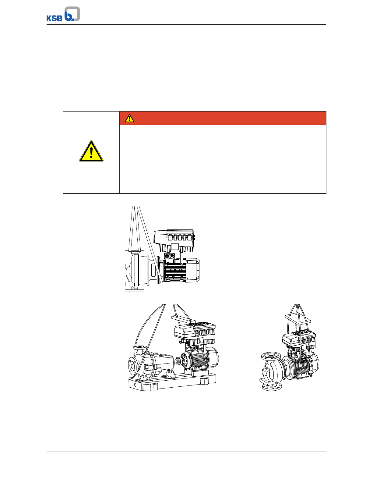
DANGER
The pump (set) could slip out of the suspension arrangement
Danger to life from falling parts!
▷ Always transport the pump (set) in the specified position.
▷ Never attach the suspension arrangement to the free shaft end or the motor
eyebolt.
▷ Give due attention to the weight data and the centre of gravity.
▷ Observe the applicable local health and safety regulations.
▷ Use suitable, permitted lifting accessories, e.g. self-tightening lifting tongs.
To transport the pump/pump set suspend it from the lifting tackle as shown.
Fig.1: Transporting a close-coupled pump set
Fig.2: Transporting a horizontal pump set
Page 11

2 Transport/Temporary Storage/Disposal
11 of 212
PumpDrive 2
Fig.3: Transporting a vertical pump set
Fig.4: Transporting the motor with frequency inverter
Fig.5: Transporting the frequency inverter with lifting gear
2.3 Storage
If the ambient conditions for storage are met, the function of the control unit is
safeguarded even after a prolonged period of storage.
Page 12

2 Transport/Temporary Storage/Disposal
12 of 212
PumpDrive 2
CAUTION
Damage during storage by humidity, dirt or vermin
Corrosion/contamination of the control unit!
▷ For outdoor storage cover the (packed or unpacked) control unit and
accessories with water-proof material.
Table5: Ambient conditions for storage
Ambient condition Value
Relative humidity 85% max. (non-condensing)
Ambient temperature -10°C to + 70°C
▪ Store the control unit in dry, vibration-free conditions and, if possible, in its
original packaging.
▪ Store the control unit in a dry room where the level of atmospheric humidity is as
constant as possible.
▪ Prevent excessive fluctuations in atmospheric humidity (see table on ambient
conditions for storage).
2.4 Disposal/recycling
The product is classified as special waste due to several installed components:
1. Dismantle product.
2. Separate materials
e.g.:
- Aluminium
- Plastic cover (recyclable plastic)
- Line chokes with copper windings
- Copper lines for internal wiring
3. Dispose of materials in accordance with local regulations or in another
controlled manner.
PCBs, power electronics, capacitors and electronic components are all special
waste.
Page 13
3 General
13 of 212
PumpDrive 2
3 General
3.1 Principles
This manual is supplied as an integral part of the type series indicated on the front
cover. The manual describes the proper and safe use of this equipment in all phases
of operation.
The name plate indicates the type series, the main operating data and the serial
number. The serial number uniquely describes the product and is used as
identification in all further business processes.
In the event of damage, immediately contact your nearest KSB service centre to
maintain the right to claim under warranty.
3.2 Target group
This operating manual is aimed at the target group of trained and qualified specialist
technical personnel.
3.3 Other applicable documents
Table6: Overview of other applicable documents
Document Contents
Operating manual Description of the proper and safe use of the
pump in all phases of operation
Wiring diagram Description of the electrical connections
Supplementary operating
manual
2)
Description of the proper and safe use of
supplementary product components
For accessories and/or integrated machinery components, observe the relevant
manufacturer's product literature.
3.4 Symbols
Table7: Symbols used in this manual
Symbol Description
✓ Conditions which need to be fulfilled before proceeding with the
step-by-step instructions
⊳ Safety instructions
⇨ Result of an action
⇨ Cross-references
1.
2.
Step-by-step instructions
Note
Recommendations and important information on how to handle
the product
2) Optional
Page 14
4 Operation
14 of 212
PumpDrive 2
4 Operation
4.1 Graphical control panel
OK
MAN
ESC
?
AUTO FUNC
OFF
3
1
2
3
4
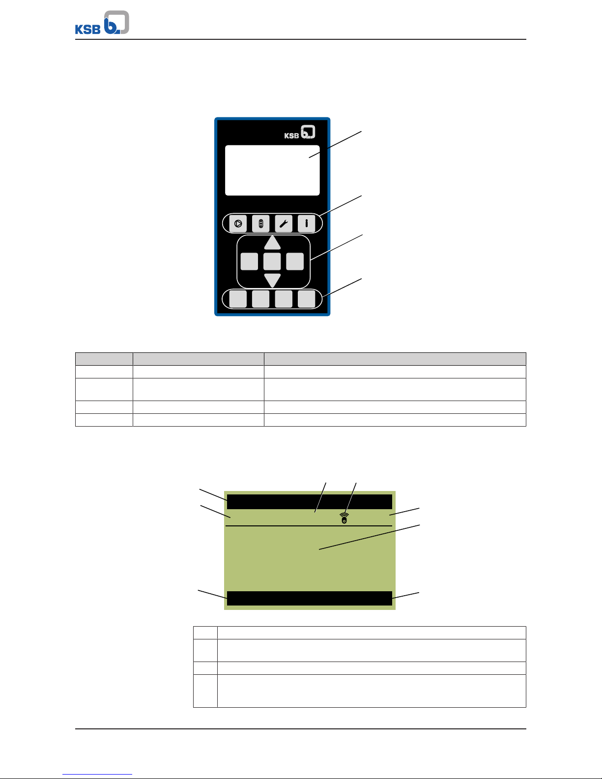
Fig.6: Graphical control panel
Table8: Description of graphical control panel
Position Description Function
1 Graphical display Displays information on frequency inverter operation
2 Menu keys Accessing the elements of the first menu level (Operation,
Diagnosis, Settings and Information)
3 Navigation keys Navigation and parameter setting
4 Operating keys Toggling operating modes
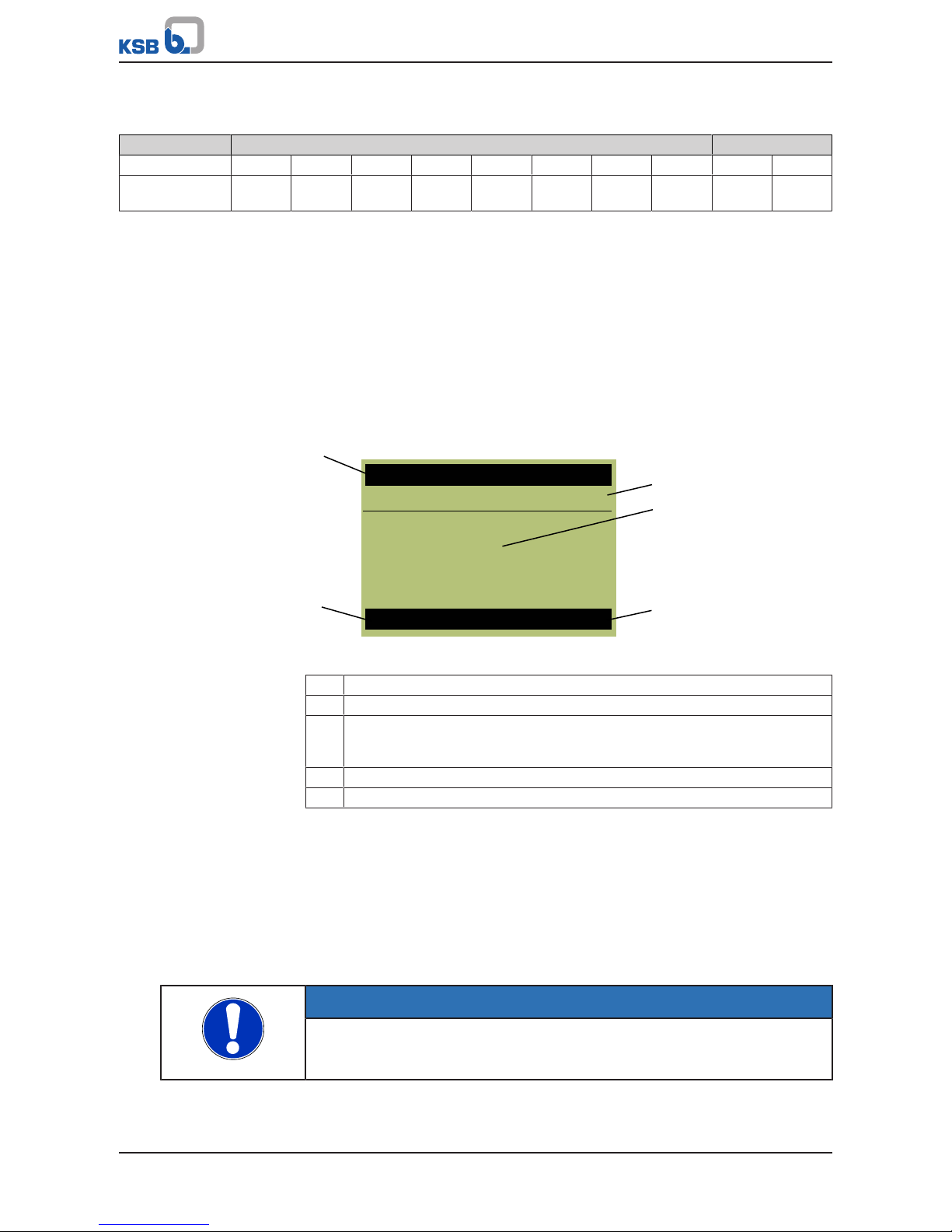
4.1.1 Graphical display
The main screen breaks down into 6areas.
C M
H
1-2-1-1
2893
rpm
17.48 m³/h
4.62 bar 642.9 V
RUN
AUTO
Speed
8
1
4
5
7
6
3
2
Fig.7: Main screen (example)
1 Motor standstill heater is switched on
2 The wireless icon illuminates when the Bluetooth module is inserted. The
wireless icon flashes when communication takes place.
3 Display of the master and login level
4 Display of up to four (4)operating values: One operating value is displayed in
large format. Three (3) operating values are displayed in small format. The
operating values scroll through cyclically.
Page 15
4 Operation
15 of 212
PumpDrive 2
5 Display of operating status
6 Display of the current operating mode
7 Parameter number of the operating value displayed in the centre
8 Name of the operating value displayed in the centre
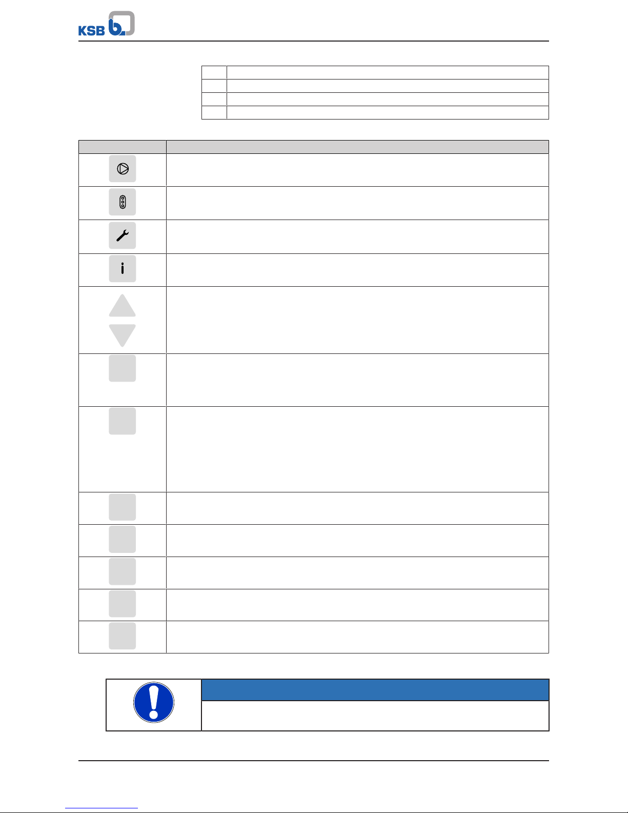
Table9: Assignment of keys
Key Function
Operation menu key
Diagnosis menu key
Settings menu key
Information menu key
Arrow keys:
▪ Move up/down in the menu options.
▪ Increase/decrease the value displayed when you are entering numerals. (When an arrow
key is pressed and held down, the response repeats in ever shorter intervals.)
ESC
Escape key:
▪ Delete/reset entry
(the entry is not saved).
▪ Move up one menu level.
OK
OK key:
▪ Confirm settings.
▪ Confirm menu selection.
▪ Move to the next digit when entering numerals.
▪ Message display: Acknowledge alert.
▪ Measured value display: Go to Favourites menu.
?
Help key:
▪ Displays a help text for each selected menu option.
MAN
MAN operating key:
▪ Starts the frequency inverter in manual operating mode.
OFF
OFF operating key:
▪ Stops the frequency inverter.
AUTO
AUTO operating key:
▪ Switches to automatic operating mode.
FUNC
FUNC operating key:
▪ Parameterisable function key
Manual mode via control panel
NOTE
After a power failure, the frequency inverter reverts to the OFF operating mode.
Manual mode must be restarted.
Page 16
4 Operation
16 of 212
PumpDrive 2
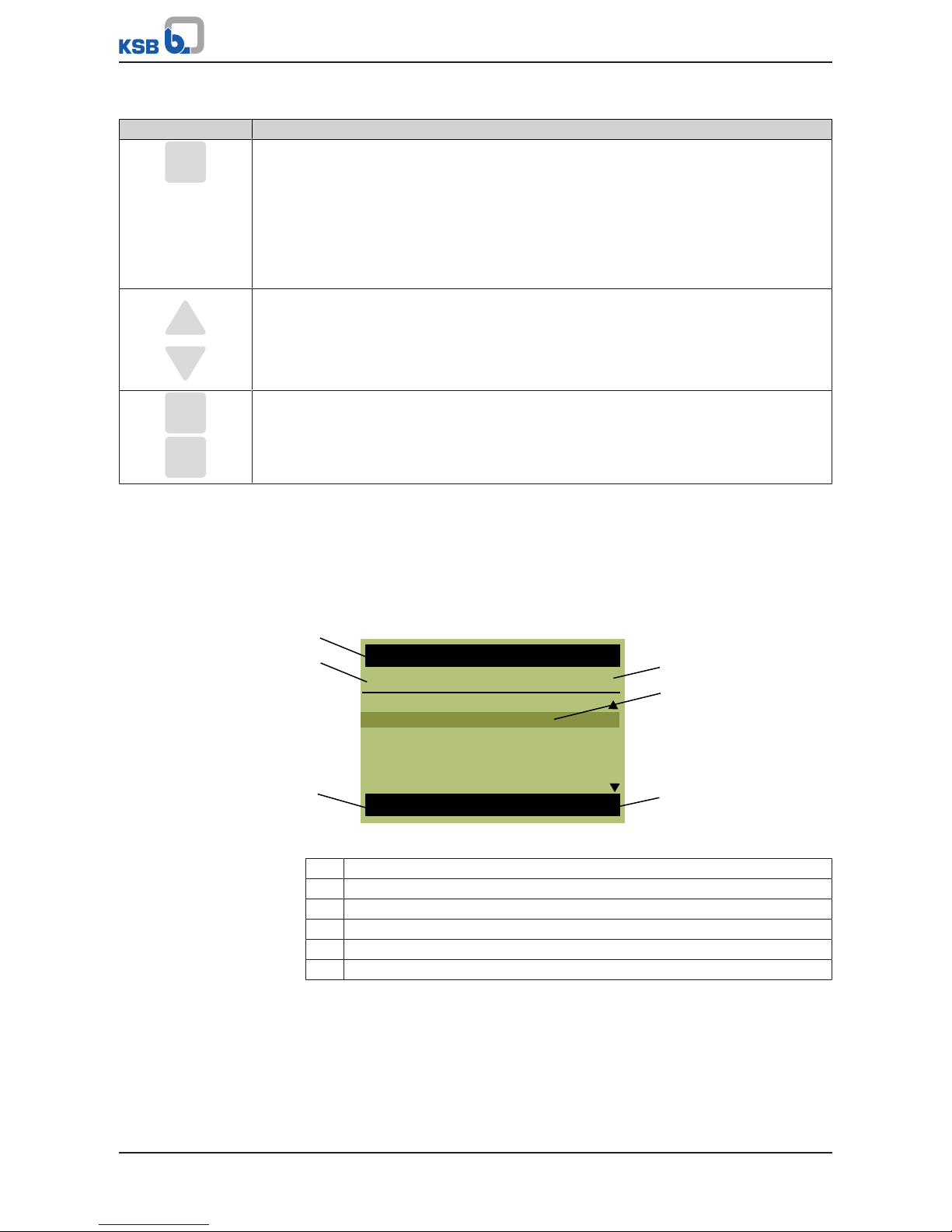
Table10: Assignment of keys for manual mode
Key Function
MAN
MAN operating key:
▪ When switching the operating mode from AUTO to MAN, the current operating speed is
used as control value (Manual) 1-3-4 and is displayed accordingly. The control point 3-6-2
must be set to Local.
▪ When switching the operating mode from OFF to MAN, the frequency inverter operates
at minimum speed. The control point 3-6-2 must be set to Local.
▪ If the control value (Manual) 1-3-4 is defined via an analog input, the analog input speed
is accepted. (ðSection8.2,Page65)
Arrow keys:
▪ Pressing the arrow keys changes and immediately accepts the control value (Manual)
1-3-4. Making a change using the arrow key has a direct effect even when not confirmed
with OK. The speed can only be changed between the set minimum speed and the
maximum speed.
ESC
OK
ESC/OK key:
▪ Press the OK or ESC key to go from digit to digit. Press the ESC key to go back. Changes
are rejected. Pressing the OK key for the right-hand digit takes you back to the main
screen.
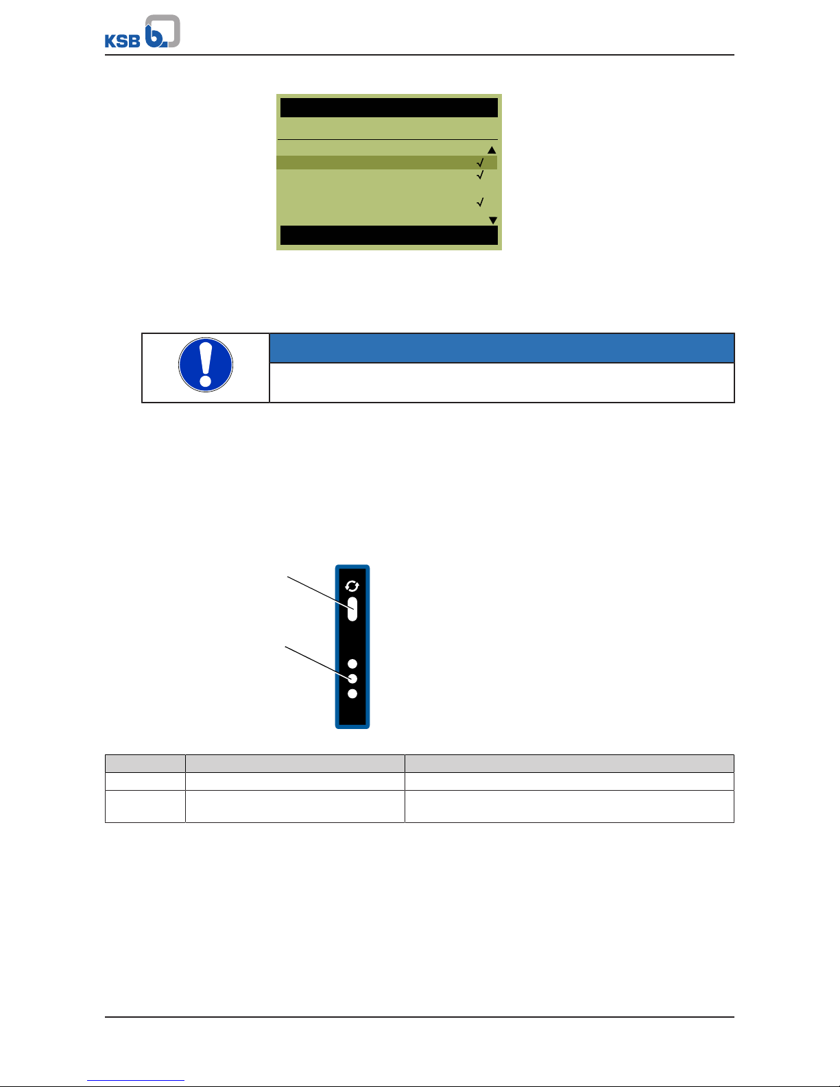
4.1.2 Menu keys
The menu keys allow you to directly access the first menu level (Operation 1-x-x-x,
Diagnosis 2-x-x-x, Settings 3-x-x-x, and Information 4-x-x-x).
The parameter numbers contain the navigation path, which helps you find a
particular parameter quickly and easily. The first digit of the parameter number
indicates the first menu level, which is called up directly via the four menu keys.
C M
STOP
3-6-1
AUTO
OFF (Open-loop Control)
Discharge Pressure
Suction Pressure
Differential Pressure
Flow Rate
Temperature (Cooling)
Type of Control
1
2
3
4
5
6
Fig.8: Menu display
1 Name of current menu/parameter
2 Parameter number of parameter selected in selection list
3 Display of the current operating mode
4 Display of the master and login level
5 Parameter/submenu selection list
6 Display of operating status
Page 17
4 Operation
17 of 212
PumpDrive 2
4.1.2.1 Menu: Operation
The Operation section contains all information required for operating the machine
and the process. This includes:
▪ Login to device with password
▪ Operating and measured values for motor, frequency inverter, pump and system
▪ Setpoints and control values
▪ Energy meter and operating hours
4.1.2.1.1 Access levels
Three access levels have been defined to prevent accidental or unauthorised access to
frequency inverter parameters:
Table11: Access levels
Access level Description
Standard (No Login) Access without password entry.
Customer Access level for the expert user with access to all parameters required for
commissioning
Customer service Access level for service personnel.
If a parameter's access level is not explicitly specified, the parameter is always
assigned the customer access level.
Table12: Access level parameters
Parameter Description Possible settings Factory setting
1-1-1 Customer Login
Log in as customer
0000...9999 0000
1-1-2 Service Login
Log in for access to special parameters for KSB
Service
0000...9999 -
1-1-4 Logout
Log out of all access levels
Run -
NOTE
If no keys are pressed for ten minutes, the system will automatically return to the
standard access level.
The password can be changed after entering the factory default password.
Table13: Parameters for changing passwords
Parameter Description Possible settings Factory setting
1-1-5 Customer Access ID
Changing the customer access ID
0000...9999 -
1-1-6 Service Access ID
Changing the service access ID
0000...9999 -
4.1.2.1.2 Operating values for input and output signals
The status of the digital inputs/relay outputs is displayed via the Digital Inputs
(1-2-4-6) and Digital Outputs (1-2-4-7) parameters.
Table14: Example of status of digital inputs (1-2-4-6). 24V is applied to digital input 1: System Start
Optional IO card Standard
Digital input DI8 DI7 DI6 DI5 DI4 DI3 DI2 DI1
Bit pattern on display 0 0 0 0 0 0 0 I
Page 18
4 Operation
18 of 212
PumpDrive 2
Table15: Example of status of digital outputs (1-2-4-7). The following is reported via relay output 1: General fault
message (configurable)
Optional IO card Standard
Digital output R8 R7 R6 R5 R4 R3 DO2 D01 R2 R1
Bit pattern on
display
0 0 0 0 0 0 0 0 0 I
4.1.2.2 Menu: Diagnosis
In the Diagnosis section, the user is provided with information about faults and
warning messages that pertain to the pump set or process. The frequency inverter
can be in fault (standstill) or warning (operational) status. The user can also find
previous messages in the history.
Messages
All monitoring and protective functions trigger warnings or alerts. These are
signalled via the amber or red LED of the LED traffic light function.
A corresponding message is output on the control panel display. If more than one
message is output, the last one is displayed. Alerts have priority over warnings.
AUTO
17.48 m³/h
4.62 bar2893 rpm
W57
rpm
C M
RUN
Low flow
1
5
2
3
4
Fig.9: Message display
1 Name of the message displayed in the centre
2 Display of the master and login level
3 Display of the message: The most recently received message is displayed in
large format on the main screen. Three operating values are displayed in small
format.
4 Display of operating status
5 Displays the current operating mode
Pending messages
If a message has occurred and been acknowledged but has not gone, this message
will be listed in the Pending Messages menu. All current messages can be displayed in
the Diagnosis menu under Pending Messages (2-1). Active warnings and alerts can
also be connected to the relay outputs.
Message history
Only messages that have come, been acknowledged, and gone are listed in the
message history. The message history can be viewed by selecting the Message History
parameter 2-2. The last 100 messages are listed here. You can use the arrow keys and
the OK key to select an entry from the list.
Acknowledging and resetting messages
NOTE
Depending on the combination of settings, the frequency inverter could
conceivably restart automatically after acknowledgement/reset or when the cause
of the malfunction or fault has been eliminated.
Acknowledgement
You can acknowledge the message once the cause has been rectified. Messages can
be acknowledged separately in the Diagnosis menu. A message can also be
acknowledged via a digital input. Digital input 2 is defaulted for this purpose.
Page 19

4 Operation
19 of 212
PumpDrive 2
Overview of warnings and alerts (ðSection11,Page189)
Messages can be acknowledged as follows:
Table16: Acknowledgement types for messages
Property of message Type of acknowledgement
Self-acknowledging Message self-acknowledges if condition for message has gone.
Self-acknowledging
(configurable)
Users can choose between self-acknowledging and acknowledging manually.
Partially selfacknowledging
Alerts that are partially self-acknowledging carry out self-acknowledgement in
increasingly large intervals after the alarm condition has gone. If the alert occurs
repeatedly within a specific time window, no additional self-acknowledgement is
carried out.
As soon as the alarm condition of a pending alert no longer exists, the time interval is
started. When this interval expires, automatic acknowledgement takes place.
If the alert occurs again within 30seconds after the time interval has started, the
interval is extended by one increment. Should this not be the case, the previous
(shorter) time interval is reverted to and corresponding action is taken again in
30seconds. The time intervals are 1second, 5seconds, 20seconds, and endless (i.e.
manual acknowledgement is required). When the 20-second interval is extended, selfacknowledgement no longer takes place.
Non-self-acknowledging Must be acknowledged manually.
Time stamp
If a message is not acknowledged and its condition comes and goes several times in
this time window, the first occurrence of the message is always used for the Message
Come time stamp. The Message Condition Gone time stamp, however, always shows
the last time the message condition was no longer active.
4.1.2.3 Menu: Settings
General settings can be made or the settings for the process optimised in the Settings
section.
4.1.2.3.1 Setting the display language
The display ships from the factory with support for 4languages (language package).
A language package can be changed using the KSB Service Tool:
Table17: Parameters for display language
Parameter Description Possible settings Factory setting
3-1-1 Language
Configurable display language
Depending on the language package:
▪ English, German, French, Italian
▪ English, French, Dutch, Danish
▪ English, Spanish, Portuguese, Turkish
▪ English, Norwegian, Swedish, Finnish
▪ English, Estonian, Latvian, Lithuanian
▪ English, Polish, Hungarian, Czech
▪ English, Slovenian, Slovakian, Croatian
▪ English, Russian, Romanian, Serbian
English, German,
French, Italian
Page 20

4 Operation
20 of 212
PumpDrive 2
4.1.2.3.2 Setting the control panel
Table18: Parameters for setting the control panel
Parameter Description Possible settings Factory setting
3-1-2-1 Operating Values on Main Screen
Display of current operating values on the main
screen
Main screen selection list -
3-1-2-2 Control Keys Require Login
Direct access to the MAN, OFF, AUTO and FUNC
operating keys can be disabled via this parameter.
▪ OFF
▪ ON
OFF
3-1-2-3 Function Key Assignment
Assigning a freely selectable function to the FUNC
key
▪ No Function
▪ System Start / Stop
▪ Setpoint (Closed-loop
Control)
▪ Control Value (Open-loop
Control)
▪ Alternative Setpoint (Closed-
loop Control)
▪ Alternative Control Value
(Open-loop Control)
▪ Immediate Pump
Changeover
▪ Immediate Functional Check
Run
▪ Language
▪ Fixed Speed 1
▪ PumpMeter Upload
▪ Remote/Local Control Point
Language
3-1-2-4 Display Contrast
Configurable contrast for the display
0...100 50
3-1-2-5 Display Backlight
Configuring the display backlight
▪ OFF
▪ ON
▪ Automatic
Automatic
3-1-2-6 Display Backlight Duration
Duration of display backlight on period in
automatic mode
0...600 30
Operating Values on Main
Screen
Up to 4operating values are simultaneously displayed on the main screen. An
operating value is displayed in large format with the associated parameter name,
parameter number and unit. Three (3) operating values are displayed in smaller
format with the associated unit. The arrow keys can be used to cycle through the
operating values. Each operating value passes through all display areas. Up to
10operating values can be selected from the predefined list for the display. The
sequence of the selection list determines the sequence of the operating values on the
main screen. If more than 4parameters are selected, the hidden parameters are also
cycled through in the background.
Selecting operating values for the main screen
1. Open parameter 3-1-2-1 in the Settings menu.
2. Using the arrow keys, select the operating value to be displayed from the list.
3. Press OK key.
4. Select additional, required operating values from the list and confirm by
pressing the OK key.
Page 21
4 Operation
21 of 212
PumpDrive 2
C M
RUN
AUTO
3-1-2-1
Speed
Motor Input Power
Motor Current
Output Frequency
Pump Suction Pressure
Pump Discharge Pressure
Operating Values on Main Scr...
Fig.10: Selecting multiple parameters from the selection list
Locking operating keys
The operating keys of the control panel can be locked via the 3-1-2-2 parameter to
prevent unauthorised operation or unauthorised acknowledgement of alerts.
Function key assignment
The FUNC operating key can be preassigned a function from a selection list.
NOTE
When the FUNC operating key is used in the System Start / Stop role, the system
must be restarted via the FUNC operating key every time the voltage is reset.
Favourites menu
Press the OK key on the main screen to call up the favourites menu, where you can
select various parameters and quickly adapt their configuration settings.
4.1.2.4 Menu: Information
All direct information about the frequency inverter is provided in the Information
section. Important details regarding the firmware version are listed here.
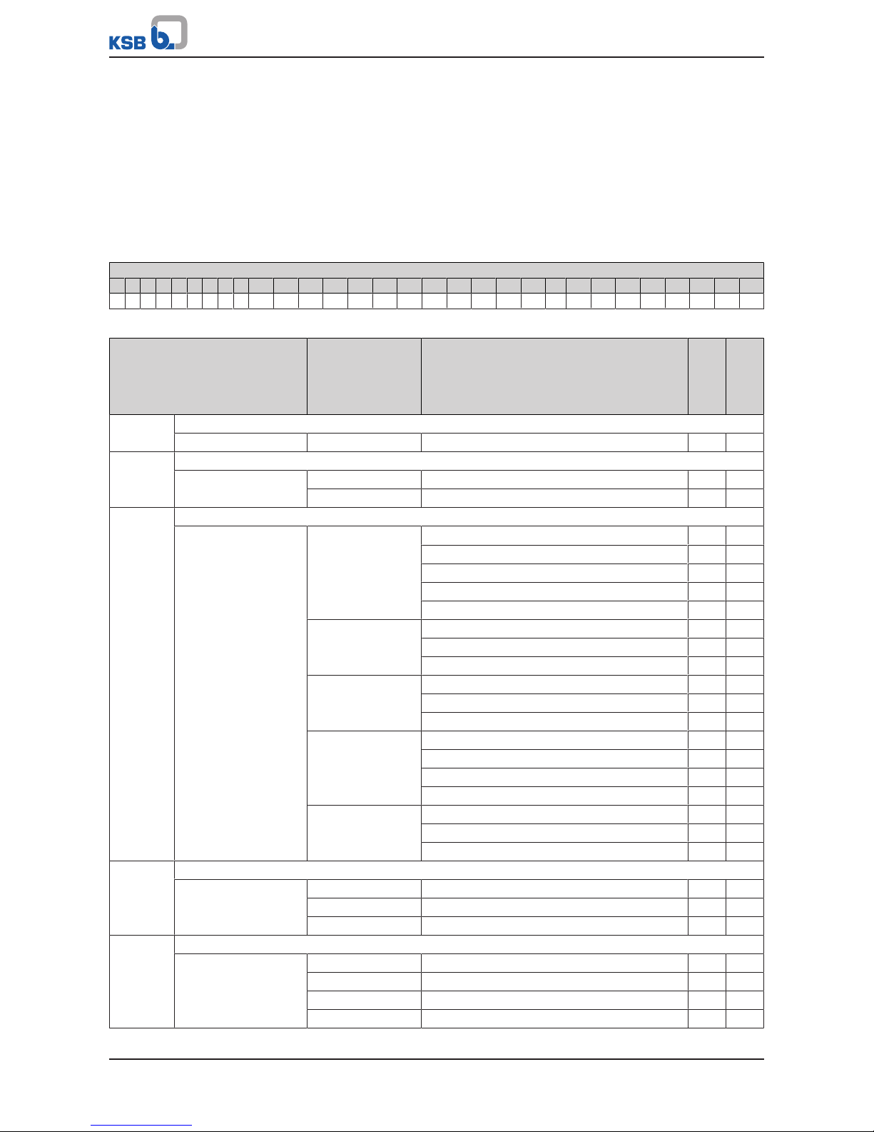
4.1.3 Service interface and LED traffic light function
2
1
Fig.11: Service interface and traffic light LEDs
Item Description Function
1 Service interface Optical interface
2 LED traffic light function The traffic light function provides information about the
system's operating status.
Service interface
The service interface allows a PC/notebook to be connected via a special cable (USB –
optical).
The following action can be taken:
▪ Configuring and parameterising the frequency inverter with the service software
▪ Software update
▪ Saving and documenting set parameters
LED traffic light function
The LED traffic light function provides information about the current PumpDrive
operating status.
Page 22

4 Operation
22 of 212
PumpDrive 2
Table19: LED description
LED Description
Red
One or more than one alert is active
Amber
One or more than one warning is active
Green
Steady light: Trouble-free operation
Page 23

5 Commissioning report
23 of 212
PumpDrive 2
5 Commissioning report
Report number: ...................................................
Purchaser
Order number ........................................................................................................................................
Customer ........................................................................................................................................
Installation location ........................................................................................................................................
Contact ........................................................................................................................................
Product
Pump type .................................................................................................................................................................
Pump works number 1. ................................................. 2. .................................................
3. ................................................. 4. .................................................
5. ................................................. 6. .................................................
Motor data ................. [kW] ..................... [A] ........................ [V] .................... [cos phi] ................... [rpm]
Type code 1. ................................................. 2. .................................................
3. ................................................. 4. .................................................
5. ................................................. 6. .................................................
Serial number 1. ................................................. 2. .................................................
(Name plate), frequency
inverter
3. ................................................. 4. .................................................
5. ................................................. 6. .................................................
Operating mode
Manual mode Application: Pressure/differential pressure/flow rate/temperature
Open-loop control mode Setpoint .......................... [Source] ............. [Unit] ................. [Value]
Closed-loop control mode Sensor .............................[sensor full-scale value]
Multiple pump
configuration
Number of frequency inverters ..... [Quantity] Number of HMIs..... [Quantity]
Master control device Number of master control devices ..... [Quantity]
Bus connection Field bus type ...................... Number of modules ..... [Quantity]
Comments
.................................................................................................................................................................................................
.................................................................................................................................................................................................
.................................................................................................................................................................................................
.................................................................................................................................................................................................
........................................................................................ ........................................................................................
KSB Customer Service/name Client/name
........................................................................................ ........................................................................................
Place, date, signature Place, date, signature
Page 24
6 Description
24 of 212
PumpDrive 2
6 Description
6.1 General description
PumpDrive is a modular, self-cooling frequency inverter which enables the motor
speed to be varied continuously by means of analog standard signals, a field bus or
the control panel.
6.2 Designation
Table20: Designation example
Item
1 2 3 4 5 6 7 8 9 10 11 12 13 14 15 16 17 18 19 20 21 22 23 24 25 26 27 28 29 30
P D R V 2 E - 0 1 1 K 0 0 M _ S 1 L E 1 E 2 P 2 _ M O O R O
Table21: Key to the designation
Item Code Description
PumpDrive 2
Eco
PumpDrive2
1-4 Generation
PDRV2 2. PumpDrive generation ✘ ✘
6 Variant
E PumpDrive 2 Eco ✘ -
- PumpDrive2 - ✘
8-13 Power
A 000K37=0,37kW ✘ ✘
000K55=0,55kW ✘ ✘
000K75=0,75kW ✘ ✘
001K10=1,1kW ✘ ✘
001K50=1,5kW ✘ ✘
B 002K20=2,2kW ✘ ✘
003K00=3kW ✘ ✘
004K00=4kW ✘ ✘
C 005K50=5,5kW ✘ ✘
007K50=7,5kW ✘ ✘
011K00=11kW ✘ ✘
D 015K00=15kW - ✘
018K50=18,5kW - ✘
022K00=22kW - ✘
030K00=30kW - ✘
E 037K00=37kW - ✘
045K00=45kW - ✘
055K00=55kW - ✘
14 Mounting option
M Motor mounting ✘ ✘
W Wall mounting ✘ ✘
C Cabinet mounting ✘ ✘
16 Motor manufacturer
K KSB ✘ ✘
S Siemens ✘ ✘
C Cantoni ✘ ✘
W Wonder ✘ ✘
Page 25

6 Description
25 of 212
PumpDrive 2
Item Code Description
PumpDrive 2
Eco
PumpDrive2
17-20 Motor type
1LE1 Siemens 1LE1/ KSB1PC3 ✘ ✘
1LA7 Siemens 1LA7/ KSB1LA7 ✘ ✘
1LA9 Siemens 1LA9/ KSB1LA9 ✘ ✘
1LG6 Siemens 1LG6/ KSB1LG6 ✘ ✘
SUPB KSB SuPremE B ✘ ✘
DMC KSB(DM) Cantoni ✘ ✘
DMW KSB(DM) Wonder ✘ ✘
21-22 Efficiency class
E1 IE1 ✘ ✘
E2 IE2 ✘ ✘
E3 IE3 ✘ ✘
E4 IE4 ✘ ✘
23-24 Number of motor poles
P2 2 poles ✘ ✘
P4 4 poles ✘ ✘
P6 6 poles ✘ ✘
26 M12 module
O None ✘ ✘
M M12 module ✘ ✘
27 Field bus module
O None ✘ ✘
L LON - ✘
P Profibus DP - ✘
M Modbus RTU ✘ ✘
B BACnet MS / TP - ✘
3)
N Profinet - ✘
3)
E Ethernet - ✘
3)
28 Optional component 1
O None ✘ ✘
I I/O extension board - ✘
29 Optional component 2
O None ✘ ✘
R Bluetooth module ✘ ✘
30 Optional component 3
O None ✘ ✘
M Master switch - ✘
3) Consult the manufacturer.
Page 26
6 Description
26 of 212
PumpDrive 2
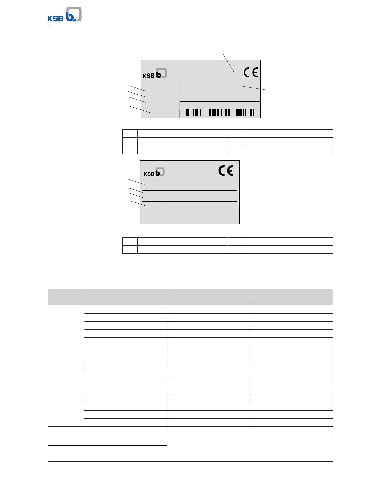
6.3 Name plate
IP55
PumpDrive
3PH 380 : 480 VAC
50-60 Hz
0105000180
18,0 A
7,5 KW
INPUT:
P D R V 2 _ _ 0 0 7K50
1
2
3
4
5
6
Fig.12: Name plate 1, frequency inverter (example)
1 Enclosure 2 Type series, size
3 Nominal power 4 Nominal current
5 Mains frequency 6 Mains voltage
IP55
PumpDrive
997257666000010002
ETN 080-065-160 GG A 11GD20150
31.07.2014
PDRV2__-015K00M_S1LE1E2P2_MPIRM
3
4
1
2
Fig.13: Name plate 2, frequency inverter (example)
1 PumpDrive type code 2 KSB order number
3 Pump designation 4 Date of manufacture
6.4 Power range and sizes
Table22: Power range4) for 2-pole (3000rpm), 4-pole (1500rpm) and 6-pole (1000) asynchronous motors and KSB
SuPremE
Size Nominal electrical power Nominal output current Mains-side input current
[kW] [A] [A]
A 0,37 1,3 1,4
0,55 1,8 2
0,75 2,5 2,7
1,10 3,5 3,7
1,50 4,9 5,2
B 2,2 6 6,3
3,0 8 8,4
4,0 10 10,4
C 5,5 14 14,6
7,5 18 18,7
11 25 25,9
D 15 33 34,1
18,5 42 43,3
22 51 52,4
30 66 67,7
E 37 81,5 83,4
4) The power ranges specified apply in full to all mounting options.
Page 27

6 Description
27 of 212
PumpDrive 2
Size Nominal electrical power Nominal output current Mains-side input current
[kW] [A] [A]
E 45 97 99
55 120 122,4
6.5 Technical data
Table23: Technical data of frequency inverter
Characteristic Value
Mains supply
Mains voltage
5)
3 ~ 380VAC - 10% to 480VAC +10%
Voltage difference between the three phases ±2% of the supply voltage
Mains frequency 50 - 60Hz ± 2 %
Mains types TN-S, TN-CS, TN-C, TT and IT mains (to IEC/EN60364)
Output data
Frequency inverter output frequency 0 - 70 Hz for asynchronous motors
0 - 140Hz for KSBSuPremE
PWM carrier frequency Range: 2 - 8 kHz
(Factory setting: 4kHz)
Phase rate of rise dv/dt
6)
5000 V/µs max. (depending on the size of the frequency
inverter)
Peak voltages 2×1,41×V
eff
Lines with a high current-carrying capacity can cause the
voltage to increase up to double the value.
Frequency inverter data
Efficiency 98 % - 95 %
7)
Noise emissions Sound pressure level of pump used + 2.5dB
8)
Environment
Enclosure IP55 (to EN 60529)
In-service ambient temperature -10°C to +50°C
In-storage ambient temperature -10 °C to +70 °C
Relative humidity Operation: 5% to 85% (non-condensing)
Storage: 5% to 95%
Transport: 95%max.
Installation altitude < 1000m above MSL, or 1 % power derating per additional
100m
Vibration resistance 16.7m/s2 max. (to EN60068-2-64)
Fluid temperature -30°C to +140°C
EMC
Frequency inverter ≤11kW EN61800-3 C1/EN55011 Class B/cable length ≤ 5m
Frequency inverter ≥ 15 kW EN 61800-3 C2/EN 55011 Class A, Group 1/cable length ≤50m
Mains feedback Integrated line chokes
Inputs and outputs
Internal power supply unit 24V ± 10 %
Maximum load 600mA DC max., short-circuit and overload-proof
5) If the mains voltage is low, the nominal torque of the motor will be lower.
6) The phase rate of rise (dv/dt) depends on the line capacity.
7) The efficiency at the nominal point of the frequency inverter varies between 98 percent for high power outputs and
95percent for low outputs, depending on the inverter's nominal power.
8) The values are for orientation purposes only. The value refers to the nominal duty point (50Hz) only. Also refer to the
pump's noise characteristics. They, too, are documented for nominal duty operation. Other values may occur during
variable speed operation.
Page 28

6 Description
28 of 212
PumpDrive 2
Characteristic Value
Residual ripple <1%
Analog inputs
Number of parameterisable analog inputs 2 (configurable for current or voltage input)
Input type Differential
Maximum voltage (with reference to GND) ± 10V
Current input 0/4 - 20mA
Input impedance 500Ohm
Accuracy 1% of full-scale value
Signal delay < 10ms
Resolution 12bit
Voltage input 0/2 - 10V
Input impedance ca. 40kOhm
Accuracy 1% of full-scale value
Signal delay < 10ms
Resolution 12bit
Reverse polarity protection Positive and negative polarity reversal possible
Analog outputs
Number of parameterisable analog outputs 1 (toggling 4 output values)
Current output 4-20mA
Maximum external working resistance 850Ohm
Output PNP transistor
Accuracy 2 % of full-scale value
Signal delay < 10ms
Reverse polarity protection Provided
Short-circuit protection and overload protection Provided
Digital inputs
Number of digital inputs 6 in total, 5 of which can be parameterised
ON level 15-30V
OFF level 0-3V
Input impedance Approx. 2 kOhm
Electrical isolation Provided, insulation voltage: 500VAC
Delay < 10ms
Reverse polarity protection Provided
Relay outputs
Number of parameterisable relay outputs 2 changeover contacts
Maximum contact rating AC: Max. 250 VAC/0.25A
DC: Max. 30 VDC/2A
PWM carrier frequency
Power derating for increased carrier frequency
Sizes A, B and C (at PWM carrier frequency > 4kHz):
I
Nominal motor current (PWM)
= I
Nominal motor current
×(1 - [f
PWM
- 4kHz]×2.5 %)
Table24: Technical data of I/O extension board
Characteristic Value
Analog inputs
Number of parameterisable analog inputs 1
Input type Differential
Maximum voltage (with reference to GND) + 10V
Current input 0/4 – 20mA
Page 29

6 Description
29 of 212
PumpDrive 2
Characteristic Value
Input impedance 500Ohm
Accuracy 1% of full-scale value
Signal delay < 10ms
Resolution 11bit
Voltage input 0/2 - 10V
Input impedance ca. 40kOhm
Accuracy 1% of full-scale value
Signal delay < 10ms
Resolution 11 bit + 1 bit sign
Reverse polarity protection Provided
Analog outputs (current output or voltage output)
Number of parameterisable analog outputs 1 (toggling 4 output values)
Current output 4 – 20mA
Maximum external working resistance 850Ohm
Output PNP transistor
Accuracy 2 % of full-scale value
Signal delay < 10ms
Reverse polarity protection Provided
Short-circuit protection and overload
protection
Provided
Voltage output 2 – 10V
Maximum output current 25mA
Output NPN transistor
Accuracy 2 % of full-scale value
Signal delay < 10ms
Reverse polarity protection Provided
Short-circuit protection and overload
protection
Provided
Digital inputs
Number of digital inputs 3 (all parameterisable)
ON level 15-30V
OFF level 0 - 3V
Input impedance Approx. 2 kOhm
Electrical isolation Provided, insulation voltage: 500VAC
Delay < 10ms
Reverse polarity protection Provided
Digital outputs
Number of digital outputs 2
Output PNP transistor
ON level 24V ±10 %
OFF level < 2V
Output current Max. 40 mA
Differential current < 100µA
Reverse polarity protection Provided
Short-circuit protection and overload protection Provided
Relay outputs
Number of parameterisable relay outputs 1 changeover contacts
5 NO contact
Page 30
6 Description
30 of 212
PumpDrive 2
Characteristic Value
Changeover contact, maximum contact rating AC: Max. 250 VAC/0.25A
DC: Max. 30 VDC/3A
NO contact, maximum contact rating AC: Max. 250 VAC/0.25A
DC: Max. 30 VDC/1A
Suitable for switching operations of contactors with a
maximum start-up current of 10A.
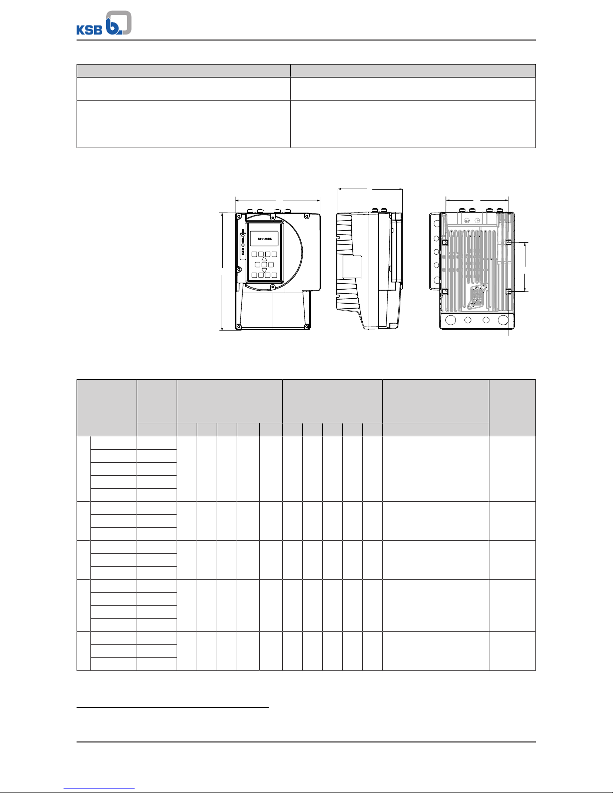
6.6 Dimensions and weights
a
b
c
d
e
F
Fig.14: Dimensions
Table25: Dimensions and weights
Size P Motor-mounted model
[mm]
Wall-/
Cabinet-mounted
model
9)
[mm]
Fastening screws/bolts Weight
10)
[kg]
[kW] a b c d e a b c d e F
A ..000K37.. 0,37 260 190 166 140 141 343 190 166 140 333 M4×10 5
..000K55.. 0,55
..000K75.. 0,75
..001K10.. 1,1
..001K50.. 1,5
B ..002K20.. 2,2 290 211 166 155 121 328 211 166 155 318 M4×10 6,5
..003K00.. 3
..004K00.. 4
C ..005K500.. 5,5 330 280 210 219 205 401 280 210 219 387 M6×12 12,5
..007K500.. 7,5
..011K000.. 11
D ..15K000.. 15 460 350 290 280 309 582 350 290 280 565 M8×14 36
..18K500.. 18,5
..22K00.. 22
..30K00.. 30
E ..37K00.. 37 700 455 340 375 475 819 455 340 375 800 M8×14 60
..45K00.. 45
..55K00.. 55
9) The dimensions provided refer to PumpDrive including the wall-mounting brackets.
10) Without motor adapter
Page 31

6 Description
31 of 212
PumpDrive 2
6.7 Mounting options
The frequency inverter is identical in design and configuration for all 3 mounting
options.
▪ Motor mounting
For the motor mounting option, the frequency inverter is mounted to the motor
via an adapter or to the pump for the Movitec configuration. Adapters for
subsequent conversion to motor mounting for existing pump systems are
available as accessories.
▪ Wall mounting
The installation kit required for the wall-mounted model is included in the scope
of supply. Installation kits for subsequent conversion to wall mounting for
existing pump systems are available as accessories.
▪ Cabinet mounting
The installation kit required for the cabinet-mounted model is included in the
scope of supply. Installation kits for subsequent conversion to cabinet mounting
for existing pump systems are available as accessories.
Page 32

7 Installation at Site
32 of 212
PumpDrive 2
7 Installation at Site
7.1 Safety regulations
DANGER
Incorrect installation
Danger to life!
▷ Install the frequency inverter in a flood-proof location.
▷ Never use the frequency inverter in potentially explosive atmospheres.
7.2 Checks to be carried out prior to installation
Place of installation
The standard configuration has IP55 enclosure protection and may only be used in
environments for which its enclosure provides adequate protection.
The place of installation must meet the following requirements:
▪ Well ventilated
▪ No direct sunlight
▪ Protected from weather
▪ Sufficient clearance for ventilation and dismantling
▪ Flood-proof
Ambient conditions
▪ Operating temperature: -10 °C to +50°C
The service life of the frequency inverter is reduced if an average temperature of
+35°C/24h is exceeded or if the inverter is operated at temperatures below 0°C
or above +40°C.
The frequency inverter switches off automatically if excessively high or low
temperatures occur.
NOTE
Contact the manufacturer if the device is to be used under ambient conditions
other than those described above.
Outdoor installation
Provide the frequency inverter with suitable protection when installed outdoors to
prevent condensation on the electronic equipment and exposure to excessive
sunlight.
7.3 Mounting PumpDrive
Depending on the selected mounting option, an adapter or installation kit is
required.
7.3.1 Motor mounting
The frequency inverter for the motor-mounted model is supplied, together with the
pump, already mounted to the motor via an adapter.
Adapters for subsequent conversion to the motor mounting configuration for
existing pump systems are available from KSB.
7.3.2 Wall/control cabinet mounting
The wall-mounted model is supplied with the installation kit required for wall
mounting as standard. Installation kits for subsequent conversion to the wall
mounting configuration for existing pump systems are available from KSB.
Page 33

7 Installation at Site
33 of 212
PumpDrive 2
The frequency inverter should rest flush against the wall so that the air flow of the
fans is directed through the heat sink.
Make sure to prevent exhaust air produced by other equipment from entering the
device's air intake in order to ensure adequate cooling of the device. The following
minimum distances must be observed:
Table26: Minimum distances for control cabinet mounting
Minimum distance from other devices Distance [mm]
Top and bottom 100
Side 20
The power dissipated in the form of heat when the frequency inverter is operated at
nominal duty values varies between 98percent for high power outputs and
95percent for low outputs, depending on the frequency inverter's nominal power.
7.4 Electrical connection
7.4.1 Safety regulations
DANGER
Incorrect electrical installation
Risk of fatal injury due to electric shock!
▷ Always have the electrical connections installed by specialist personnel.
▷ Observe the technical specifications of the local and national energy supply
companies.
DANGER
Unintentional start-up
Risk of fatal injury due to electric shock!
▷ Disconnect the frequency inverter from the mains before carrying out any
maintenance and installation work.
▷ Prevent the frequency inverter from being re-started unintentionally when
carrying out any maintenance and installation work.
DANGER
Contact with live components
Risk of fatal injury due to electric shock!
▷ Never remove the centre housing part from the heat sink.
▷ Mind the capacitor discharge time.
After switching off the frequency inverter, wait 10minutes until dangerous
voltages have discharged.
WARNING
Direct connection between power supply and motor connection (bypass)
Damage to the frequency inverter!
▷ Never establish a direct connection between the power supply and motor
connection (bypass) of the frequency inverter.
Page 34

7 Installation at Site
34 of 212
PumpDrive 2
WARNING
Simultaneous connection of several motors to the frequency inverter output
Damage to the frequency inverter!
Fire hazard!
▷ Never simultaneously connect several motors to the frequency inverter output.
CAUTION
Improper dielectric test
Damage to the frequency inverter!
▷ Never carry out dielectric tests on frequency inverter components.
▷ Only carry out dielectric tests on the motor, motor connection cable, or power
cable after having disconnected the frequency inverter connections.
NOTE
Depending on the combination of settings, the frequency inverter could
conceivably restart automatically after acknowledgement/reset or when the cause
of the malfunction or fault has been eliminated.
The frequency inverter is equipped with electronic safety devices, which in case of a
disturbance or malfunction, trip and de-energise the inverter, causing it to stop.
Use only the available cable gland holes (if necessary, in combination with double
cable glands) for establishing the cable connections. Any additional drilling could
generate metal chips and damage the equipment.
7.4.2 Information for planning the system
7.4.2.1 Power/connection cables
Selecting the power/connection cables
The type of connection cable you choose depends on various factors such as, for
example, the type of connection, the ambient conditions and the type of system.
Connection cables must be used in accordance with their intended use, and the
manufacturer specifications regarding nominal voltage, current, operating
temperature and thermal effects must be observed.
Power/connection cables must not be routed across or near hot surfaces unless they
have been designed for this kind of application.
When they are used in mobile system components, flexible or highly flexible power/
connection cables must be employed.
The cables used for connections to permanently installed devices should be as short
as possible and be properly connected to these devices.
Different earth bus bars should be used for control and power/motor connection
cables.
Power cable
Unshielded cables can be used as power cables.
The power cables must be designed with a cross-section suitable for the nominal
mains current.
If a mains contactor is used in the power cable (before the frequency inverter), this
must be configured for an AC1 duty rating; the rated current values of the frequency
inverters used are added and the result is increased by 15%.
Motor connection cable
Shielded cables must be used as motor connection cables.
Control cable
Shielded cables must be used as control cables.
Page 35

7 Installation at Site
35 of 212
PumpDrive 2
NOTE
Lines of type J-Y (ST) Y are not suitable for used as control cables.
1 2 3
Fig.15: Structure of electric cable
1 Wire end sleeve 2 Core
3 Cable
Table27: Cable cross-section, control terminals
Control terminal Core cross-section [mm²] Cable diameter
11)
[mm]
Rigid cores Flexible cores Flexible cores with
wire end sleeves
Terminal strip A, B, C 0,2-1,5 0,2-1,0 0,25-0,75 M12: 3,5-7,0
M16: 5,0-10,0
Table28: Power/connection cable properties
Size Power Cable gland for Mains-side
input
current
12)
Maximum
core cross-
section
Cable cross-
section
KSBmotor
cable
Mains
power
cable
Sensor
cable
Motor
cable
PTC
thermistor
[kW] [A] [mm²]
A .. 000K37 .. 0,37 M20 M16 M20 M16 1,4 2,5 2,5
.. 000K55 .. 0,55 2,0
.. 000K75 .. 0,75 2,7
..001K10.. 1,1 3,7
B .. 001K50 .. 1,5 M25 M16 M25 M16 5,2 2,5
.. 002K20 .. 2,2 6,3
.. 003K00 .. 3 8,4
.. 004K00 .. 4 10,4
C ..005K500.. 5,5 M32 M16 M32 M16 14,6 16 4
..007K500.. 7,5 18,7
..011K000.. 11 25,9 6
D ..15K000.. 15 M40 M32 M20 M40 34,1 50 10
..18K500.. 18,5 43,3 16
..22K00.. 22 52,4 16
..30K00.. 30 67,7 25
E ..37K00.. 37 M63 M32 M20 M63 83,4 95 35
..45K00.. 45 99 50
..55K00.. 55 122,4 70
11) Impairment of protection provided by enclosure when cable diameters other than those specified are used.
12) Observe the information on the use of line chokes provided in the Accessories and Optional Equipment section.
Page 36

7 Installation at Site
36 of 212
PumpDrive 2
Length of motor connection cable
If the frequency inverter is not mounted on the motor to be controlled, longer motor
connection cables may be required. The stray capacitance of the connection cables
may result in high-frequency discharge currents flowing to ground. The sum of the
discharge currents and motor current may exceed the output-side rated current of
the frequency inverter. This will activate the frequency inverter's protection
equipment and the motor will be stopped. The following motor connection cables
are recommended depending on the power range:
Table29: Length of motor connection cable
Power range
[kW]
Maximum cable length
[m]
Stray capacitance
[nF]
≤ 11 (Class B) 5 ≤ 5
≥ 15kW (class A, group 1) 50 ≤ 5
Output filter
Output filters can only be used in conjunction with an asynchronous motor.
If longer connection cables than those listed above are required or the connection
cable's stray capacitance value exceeds the above values, we recommend installing a
suitable output filter between the frequency inverter and the motor to be controlled.
These filters reduce the voltage ramp-up time of the frequency inverter output
voltages and limit their peaks.
7.4.2.2 Electrical protection device
Back-up fuses
Provide three fast-acting fuses in the mains power supply line to the frequency
inverter. The fuse size must be suitable for the nominal mains current supplied to the
frequency inverter.
Motor protection switch
Separate motor protection is not required because the frequency inverter has its own
safety devices (e.g. electronic overcurrent trip). Available motor protection switches
must be dimensioned in accordance with the nominal motor current.
Residual current device
If fixed connections and appropriate supplementary earthing are used (cf.
DINVDE0160), residual current devices (RCDs) are not mandatory for frequency
inverters.
If residual current devices are used, three-phase frequency inverters must in
accordance with DIN VDE 0160 be connected via universal AC/DC sensitive RCDs, as
potential direct-current components may cause standard AC sensitive RCDs to either
fail to respond or respond erroneously.
Table30: Residual current device to be selected
Size Rated current [mA]
A, B and C 150
D and E 300
If you use a long shielded cable for the mains/motor connection, the residual-current
monitoring device may be triggered by the discharge current that flows to earth
(triggered by the carrier frequency). Remedies: Replace the RCD (residual current
device) or lower the response limit.
7.4.2.3 Information on electromagnetic compatibility
Electromagnetic interference from other electrical devices can affect the frequency
inverter. Interference can also be emitted by the frequency inverter itself, however.
The interference emitted by the frequency inverter is generally conducted through
the motor connection cables. The following measures are proposed for RFI
suppression:
▪ Shielded motor connection cables for line lengths >70cm
(especially recommended for frequency inverters with low power ratings)
▪ Metal cable ducts made from a single piece with a minimum coverage of 80% (if
shielded connection cables cannot be used)
Installation at site/
environment
For more effective shielding, install the frequency inverter in a metal cabinet.
Page 37

7 Installation at Site
37 of 212
PumpDrive 2
When installing the power components in the control cabinet, make sure they are
not too close to other devices (control and monitoring devices).
Maintain a minimum distance of 0.3metres between the cabling and power
components as well as other cabling in the control cabinet.
Connecting cables
Use different earth bus bars for the control cable and power/motor connection cable.
The shield on the power/connection cable must consist of a single piece and be
earthed at both ends either just on the appropriate earth terminal or on the earth
bus bar (do not connect it to the earth bus bar in the control cabinet).
The shielded cable ensures that the high-frequency current, which normally flows as
a discharge current from the motor housing to earth or between the individual
conductors, now flows through the shielding.
The shield for the control cable (connection on frequency inverter side only) also
serves as protection against radiated emissions and must be connected to the
designated connection points in the control cable terminal housing.
Fig.16: Connecting a shield
In applications with long shielded motor cables, additional reactive resistors or
output filters must be provided to compensate the capacitive stray current to earth
and reduce the rate of voltage rise on the motor. These measures help reduce radio
frequency interference further. Using just ferrite rings or reactive resistors does not
ensure compliance with the limit values defined in the EMC directive.
NOTE
If you are using shielded cables that are longer than 10 m, check the stray
capacitance to ensure that the diffusion between the phases or to earth is not
excessive, which could cause the frequency inverter to stop.
Routing cables
Route control cable and power/motor connection cable in separate cable ducts.
When routing the control cable observe a minimum distance of 0.3metres between
the control cable and the power/motor connection cables.
If you cannot avoid crossing control and power/motor connection cables, you should
cross them at 90degrees to each other.
7.4.2.4 Earth connection
The frequency inverter must be properly earthed.
To ensure greater interference immunity, a wide contact face is required for the
different earth connections.
In the case of cabinet mounting, use two separate copper earth bus bars (mains
power supply/motor connection and control connection bar) with a suitable size and
cross-section for earthing the frequency inverter. All the earth connections are
connected to these.
The bars are connected to the earthing system at one point only.
The control cabinet is then earthed via the mains earthing system.
7.4.2.5 Line chokes
The line input currents indicated are for orientation only; they refer to operation at
nominal rating. These currents may vary depending on the actual line impedance. In
low-impedance mains, higher currents may occur.
To limit the line input current, external line chokes can be used alongside the line
chokes already integrated (in the power range up to and including 45 kW). Line
chokes also reduce mains feedback and improve the power factor. The scope of
DINEN 61000-3-2 must be heeded.
Appropriate line chokes are available from KSB. (ðSection12.2.8,Page205)
Page 38

7 Installation at Site
38 of 212
PumpDrive 2
7.4.2.6 Output filter
The maximum cable lengths must be maintained in order to meet RFI suppression
requirements to EN55011. Output filters are required if the maximum cable lengths
are exceeded.
Technical data available on request. (ðSection12.2.8,Page205)
7.4.3 Electrical connection
7.4.3.1 Removing the housing cover
DANGER
Contact with live components
Risk of fatal injury due to electric shock!
▷ Never remove the centre housing part from the heat sink.
▷ Mind the capacitor discharge time.
After switching off the frequency inverter, wait 10minutes until dangerous
voltages have discharged.
The housing cover consists of a C-shaped housing cover panel. The terminals of the
power and motor connection cables are additionally guarded by a protective cover to
prevent them from being touched.
C-shaped housing cover
Fig.17: C-shaped housing cover
1. Remove the cross-recessed head screws on the C-shaped cover.
2. Remove the C-shaped cover.
Page 39

7 Installation at Site
39 of 212
PumpDrive 2
Protective cover
Fig.18: Prying open the protective cover
1. Sizes A, B and C: The protective cover for connecting the power and motor
connection cables is push-fit. Before connecting the power and motor
connection cables, carefully pry open the protective cover using a wide
screwdriver.
Sizes D and E:Undo the screws on the protective cover.
Fig.19: Removing the protective cover
2. Remove the protective cover.
Page 40

7 Installation at Site
40 of 212
PumpDrive 2
7.4.3.2 Overview of terminal strips
L1 L2 L3
LINE
PE U V W
MOTOR
1
2
C1
C2
C3
C4
C5
C6
C7
C8
C9
C10
B1
B2
B3
B4
B5
B6
B7
B8
B9
B10
A1
A2
A3
A4
A5
A6
A7
A8
A9
A10
DI-EN
+24V
GND
DI4
DI3
DI2
DI1
+24V
DICOM1
DI5
AO1-GND
AO1
AIN2 +
+24V
AIN1 +
+24V
GND
GND
COM2
NO2
COM1
NC2
+24V
GND
+24V
AIN2 -
AIN1 -
GND
NC1
NO1
P TC
MOTOR
PE
+ BR -
Fig.20: Overview of terminal strips
1 Mains and motor connection 2 Control cables
7.4.3.3 Connecting mains and motor
DANGER
Touching or removing the terminals and connectors of the braking resistor
Risk of fatal injury due to electric shock!
▷ Never open or touch the terminals and connectors of the braking resistor.
Page 41

7 Installation at Site
41 of 212
PumpDrive 2
CAUTION
Incorrect electrical installation
Damage to the frequency inverter!
▷ Never fit a contactor (in the motor connection cable) between the motor and
the frequency inverter.
1. Route the mains or motor connection cables through the cable glands and
connect to the specified terminals.
2. Connect the line for a PTC connection/PTC thermistor to the PTC terminal strip
(3).
NOTE
In the event of a short circuit in the winding (short circuit between phase and PTC),
a fuse trips and prevents carryover of low voltages to the low-voltage level. In the
case of a fault or malfunction, this fuse can only be replaced by KSB service
personnel.
Size A
L1 L2 L3
LINE
PE U V W
MOTOR
PTC
MOTOR
PE
-
L1
L2
L3
N
PE
1
2
3
4
5
M
3~
BR
+
6
6
Fig.21: Establishing the power supply and motor connections, size A
① Mains connection ② Motor connection
③ PTC connection ④ Braking resistor
⑤ Motor PTC ⑥ Jumper for IT mains
Page 42

7 Installation at Site
42 of 212
PumpDrive 2
Size B
L1 L2 L3
LINE
PE U V W
MOTOR
PTC
MOTOR
PE
-
L1
L2
L3
N
PE
1
2
3
4
5
M
3~
BR
+
6
6
Fig.22: Establishing the power supply and motor connections, size B
① Mains connection ② Motor connection
③ PTC connection ④ Braking resistor
⑤ Motor PTC ⑥ Jumper for IT mains
Size C
L1 L2 L3
LINE
PE U V W
MOTOR
PTC
MOTOR
PE
-
L1
L2
L3
N
PE
1
2
3
4
5
M
3~
BR
+
6
Fig.23: Establishing the power supply and motor connections, size C
① Mains connection ② Motor connection
③ PTC connection ④ Braking resistor
⑤ Motor PTC ⑥ Jumper for IT mains
Page 43

7 Installation at Site
43 of 212
PumpDrive 2
Size D
L1 L2 L3
LINE
PE U V W
MOTOR
PTC
MOTOR
PE
-
L1
L2
L3
N
PE
1
2
3
4
5
M
3~
BR
+
6
Fig.24: Establishing the power supply and motor connections, size D
① Mains connection ② Motor connection
③ PTC connection ④ Braking resistor
⑤ Motor PTC ⑥ Jumper for IT mains
Size E
L1 L2 L3
LINE
PE U V W
MOTOR
PTC
MOTOR
PE
-
L1
L2
L3
N
PE
1
2
3
5
M
3~
BR
+
6
4
Fig.25: Establishing the power supply and motor connections, size E
① Mains connection ② Motor connection
③ PTC connection ④ Braking resistor
⑤ Motor PTC ⑥ Jumper for IT mains
Connecting motor
monitoring devices (PTC/
PTC thermistor)
Connect the cores for a PTC connection/PTC thermistor to the PTC terminal strip (3). If
no PTC connection is available on the motor side, parameter 3-2-3-1 (PTC Analysis)
must be deactivated.
Page 44

7 Installation at Site
44 of 212
PumpDrive 2
IT mains
DANGER
Contact with live components
Risk of fatal injury due to electric shock!
▷ Never remove the centre housing part from the heat sink.
▷ Mind the capacitor discharge time.
After switching off the frequency inverter, wait 10minutes until dangerous
voltages have discharged.
Jumper in IT mains
If the frequency inverter is to be used in an IT mains, the relevant IT mains jumpers
(See Figs. "Establishing the power supply and motor connections, size A" and
"Establishing the power supply and motor connections, size B") must be removed.
7.4.3.3.1 Connecting the power supply when the master switch is installed
If the optional master switch is in the OFF position, the frequency inverter and the
motor are disconnected from the mains.
Page 45

7 Installation at Site
45 of 212
PumpDrive 2
DANGER
Opening the protective cover with the master switch in the OFF position
Risk of fatal injury due to electric shock!
▷ Disconnect the frequency inverter from the mains before carrying out any
maintenance and installation work.
▷ Prevent the frequency inverter from being re-started unintentionally when
carrying out any maintenance and installation work.
ü The master switch has been installed in the protective cover.
1. Guide the power cable through the cable gland.
L1 L2 L3
LINE
PE U V W
MOTOR
PTC
MOTOR
PE
-
L1
L2
L3
N
PE
1
2
3
4
5
M
3~
BR
+
L1 L2 L3PE
7
8
6
6
Fig.26: Example of power supply connection and motor connection to designated
terminals, size B
① Mains connection ② Motor connection
③ PTC connection ④ Braking resistor
⑤ Motor PTC ⑥ Jumper for IT mains
⑦ Power supply connection terminal
for master switch version
⑧ Master switch
2. Sizes A, B and C: Connect the power cable and the motor connection cable to
the designated terminals on the inside of the protective cover.
Sizes D and E: Connect the power cable and motor connection cable directly to
the master switch.
Page 46

7 Installation at Site
46 of 212
PumpDrive 2
8
PE L1 L2
L3
L1 L2 L3
LINE
PE U V W
MOTOR
PTC
MOTOR
PE
-
L1
L2
L3
N
PE
1
2
3
4
5
M
3~
BR
+
6
Fig.27: Example of power supply connection and motor connection to designated
terminals, size D
① Mains connection ② Motor connection
③ PTC connection ④ Braking resistor
⑤ Motor PTC ⑥ Jumper for IT mains
⑧ Master switch
7.4.3.3.2 Directly connect motor cable without motor connector (for sizes A and B
only)
DANGER
Improper electrical connection
Risk of fatal injury due to electric shock!
▷ Never simultaneously use the motor connector with a motor cable that is
directly connected to the motor terminals.
▷ Never touch terminals and connectors of the motor connector.
When directly connecting a motor line to the designated motor terminals (U, V, W),
the motor connector fitted at the factory must first be removed.
Fig.28: Disconnecting the cores of the motor connector
1. Disconnect the cores of the motor connector at terminals U, V and W.
Page 47

7 Installation at Site
47 of 212
PumpDrive 2
Fig.29: Removing the motor connector
2. Remove the motor connector from the heat sink.
Fig.30: Inserting and fastening cover
3. Close the opening in the heat sink using the kit accompanying the frequency
inverter (comprising a cover, gasket and bolts/screws).
NOTE
IP55 enclosure protection as specified in the technical data is only provided if the
cover has been fitted properly.
7.4.3.3.3 Retrofitting a frequency inverter for a KSB SuPremE B2 motor (for sizesC, D
and E only)
Fig.31: Plug
The heat sink is closed with a plug. The following steps must be carried out to retrofit
for a KSB SuPremE B2 motor.
1. Remove screwed-in plug.
Fig.32: Removing the plug
2. Remove the nut from the plug inside the frequency inverter.
NOTE
IP55 enclosure protection as specified in the technical data is only provided if the Oring has been fitted properly.
Page 48

7 Installation at Site
48 of 212
PumpDrive 2
Fig.33: Inserting the O-ring
3. Place O-ring onto adapter.
DANGER
Pinching of power and motor connection cables
Risk of fatal injury due to electric shock!
▷ Never damage the insulation of the power and motor connection cables when
inserting into the opening of the frequency inverter.
Fig.34: Inserting motor
cables
4. Place the frequency inverter onto the motor adapter of the KSB SuPremE B2
motor and insert the motor cables of the KSB SuPremE B2 motor into the
opening of the frequency inverter.
5. Connect the motor cables as described. (ðSection7.4.3.3,Page40)
Fig.35: Connecting the
motor cables
6. Connect the PTC cables that are supplied as standard with the KSB SuPremE B2
motor.
7. Close the frequency inverter with the protective cover and the housing cover.
7.4.3.3.4 Installing the line choke and output filter
L1
L2
L3
L
C
X
C
Y
R'
R
PE
Fig.36: Installing line choke and output filter
Transformer
L
PE
C
X
C
Y
R'
R
Output filter
(for asynchronous motors only)
Line choke Motor
(asynchronous motor)
Line choke
The line input currents may vary depending on the actual line impedance. In lowimpedance mains, higher currents may occur. To limit the line input current, external
line chokes can be used alongside the line chokes already integrated in the frequency
inverter (in the power range up to and including 55kW).
Output filter
Output filters can only be used in conjunction with an asynchronous motor.
Page 49

7 Installation at Site
49 of 212
PumpDrive 2
If longer connection cables than those listed above are required or the connection
cable's stray capacitance value exceeds the above values, we recommend installing a
suitable output filter between the frequency inverter and the motor to be controlled.
These filters reduce the voltage ramp-up time of the frequency inverter output
voltages and limit their peaks.
1. Install a line choke in series (in the power cable) upstream of the frequency
inverter.
2. Install an output filter in series in the motor connection cable downstream of
the frequency inverter.
7.4.3.4 Establishing an earth connection
The frequency inverter must be earthed.
Observe the following when establishing the earth connection:
▪ Ensure that the cable lengths are as short as possible.
▪ Use different earth bus bars for the control and power/motor connection cables.
▪ The earth bus bar of the control cable must not be affected by currents from the
power/motor connection cables since this could be a source of interference.
Connect the following to the earth bus bar of the power/motor connection cable:
▪ Motor earthing connections
▪ Housing of the frequency inverter
▪ Shielding of the power/motor connection cable
Connect the following to the earth bus bar of the control cable:
▪ Shielding of the analog control connections
▪ Shielding of the sensor cables
▪ Shielding of the field bus connection cable
Installing multiple
frequency inverters
Fig.37: Establishing an earth connection
If you are installing more than one frequency inverter, the star configuration is
recommended.
7.4.3.5 Installing and connecting the M12 module
The M12 module can be used to connect multiple frequency inverters to implement
dual or multiple pump configurations. The M12 module also allows PumpMeter to be
connected to the frequency inverter via Modbus.
Page 50

7 Installation at Site
50 of 212
PumpDrive 2
DC
BA
1
3
2
Fig.38: M12 module
1
Connection for dual/multiple pump configurations (KSB device
bus)
C - D
2 Connection for PumpMeter (Modbus) A
3 Connector for the bus cable crosslink (Modbus) B
▪ Can be retrofitted
▪ Internal T-connector (bus looped through) [uninterruptible even in the event of a
frequency inverter power failure]
▪ Pre-configured cables (ðSection12.2,Page197)
▪ Connector for self assembly (ðSection12.2,Page197)
The M12 slot module can be fitted in an available slot of the frequency inverter.
Page 51

7 Installation at Site
51 of 212
PumpDrive 2
Blind cover
1
1
Fig.39: Blind cover
1 Blind cover
1. Unscrew the cross recessed head screws in the blind cover.
2. Remove the blind cover.
M12 module
Fig.40: Inserting the M12
module
1. Carefully insert the M12 module in the open slot. The M12 module is guided on
rails until it engages in the contact.
Fig.41: Securing the M12
module
2. Secure the M12 module using the 4 cross recessed head screws. IP55 enclosure
protection is not provided until the screws have been tightened.
CAUTION
Incorrect assembly
Impairment of protection provided by the enclosure (protection may be
compromised)!
▷ Cover unused M12 sockets of the M12 module with a cap (included in the scope
of supply).
Connecting dual and multiple pump configurations
Designing dual and multiple pump configurations via a cable pre-configured
especially for this connection (see Accessories)
Page 52

7 Installation at Site
52 of 212
PumpDrive 2
DC
BA
DC
BA
21 3
Fig.42: Connecting M12 modules in dual and multiple pump configurations
1 Connection for dual/multiple pump configuration, PumpDrive No.1
2 Pre-configured bus cable for dual and multiple pump configuration
(colour: light purple, connector: angled, connector: angled)
3 Connection for dual/multiple pump configuration, PumpDrive No.2
NOTE
Terminating resistors (refer to KSB accessories) that can be connected to the
unassigned M12 connector (C or D) at the M12 module are required for the bus
terminator.
Connecting PumpMeter in single-pump configurations
Use pre-configured cables to connect PumpMeter (ðSection12.2,Page197)
NOTE
Connect PumpMeter (Modbus) to the M12 module, input A.
DC
BA
1
2
3
Fig.43: Connecting the M12 module to PumpMeter in single-pump configurations
1 PumpMeter: Modbus connection
2 Pre-configured bus cable for connecting PumpMeter to M12 module
(colour: black, socket: straight, connector: angled)
3 M12 module: Connection for PumpMeter (Modbus)
Connecting PumpMeter in dual and multiple pump configurations
Pre-configured crosslink cables can be used to switch the PumpMeter Modbus signal
from frequency inverter to frequency inverter. (ðSection12.2,Page197)
Page 53

7 Installation at Site
53 of 212
PumpDrive 2
DC
BA
DC
BA
DC
BA
1 2
3
4
5 6
87
9 1010
Fig.44: Connecting PumpMeter in dual and multiple pump configurations
1 PumpMeter: Modbus connection
2 Pre-configured bus cable for connecting PumpMeter to M12 module
(colour: black, socket: straight, connector: angled)
3 M12 module, socket A: Connection for PumpMeter (Modbus)
4 M12 module, socket B: Connection for bus cable crosslink (Modbus)
5 Pre-configured bus cable crosslink for redundant connection of PumpMeter
(colour: black, connector: angled; connector: angled)
6 M12 module, socket A: Connection for bus cable crosslink (Modbus)
7 Connection for dual/multiple pump configuration, PumpDrive No.1
8 Pre-configured bus cable for dual and multiple pump configuration
(colour: light purple, connector: angled, connector: angled)
9 Connection for dual/multiple pump configuration, PumpDrive No.2
10 Terminating resistor
Pin assignment
2
1
4 3
5
Fig.45: M12 module standard assignment for M12 socket as viewed looking at the
mating face
Table31: Pin assignment, M12 module, input A/B
Pin Conductor colour coding M12 socket A assignment
parameterised for
PumpMeter Modbus
M12 socket B assignment
parameterised for
PumpMeter Modbus
M12 socket A and B
assignment
parameterised as analog
input
1 Brown 24 V output (supply to
PumpMeter)
24 V output (supply to
PumpMeter)
24 V output (supply to
PumpMeter)
2 Blue 0V 0 V 0 V
3 White D- D+ Input (4 - 20 mA)
4 Grey D+ D- 5 - - - Vent opening
Table32: Pin assignment, M12 module, input C/D
Pin Conductor colour coding M12 socket C and D assignment
1 - Shielding
2 Red 3 Black CAN GND
4 White CAN H
Page 54

7 Installation at Site
54 of 212
PumpDrive 2
Pin Conductor colour coding M12 socket C and D assignment
5 Blue CAN L
Thread - Shielding
7.4.3.6 Installing and connecting the field bus module
The field bus modules are available as plug-in modules in the following variants:
▪ Modbus RTU module
▪ Profibus DP module
▪ LON module
The field bus modules have the following properties:
▪ Can be retrofitted
▪ Internal T-connector (bus looped through) [uninterruptible even in the event of a
frequency inverter power failure]
▪ Pre-configured cables (ðSection12.2,Page197)
▪ Connector for self assembly (ðSection12.2,Page197)
Installing the field bus module
The field bus module can be fitted in an available slot of the frequency inverter.
Page 55

7 Installation at Site
55 of 212
PumpDrive 2
Blind cover
1
1
Fig.46: Blind cover
1 Blind cover
1. Unscrew the cross recessed head screws in the blind cover.
2. Remove the blind cover.
Field bus module
Fig.47: Inserting the field
bus module
1. Carefully insert the field bus module into the open slot. The plug-in module is
guided on rails until it engages in the contact.
Fig.48: Securing the M12
module
2. Secure the field bus module using the 4 cross recessed head screws. IP55
enclosure protection is not provided until the screws have been tightened.
CAUTION
Incorrect assembly
Impairment of protection provided by the enclosure (protection may be
compromised)!
▷ Cover unused M12 sockets of the M12 module with a cap (included in the scope
of supply).
Page 56

7 Installation at Site
56 of 212
PumpDrive 2
Connecting the field bus module
Observe the following when connecting the field bus module:
▪ Before the bus connection is established among the nodes, potential equalisation
must have been implemented and checked.
▪ To ensure high-frequency shielding, use suitable, shielded cables for the
respective field bus and install them in accordance with EMC requirements.
▪ A minimum distance of 0.3metres is recommended between such cables and
other electric conductors.
▪ Do not use the bus cable to make any further connections in addition to the field
bus module (for example, 230 V alert and 24 V start).
CAUTION
Incorrect installation
Damage to the field bus module!
▷ Never supply the field bus module with voltage using the M12 connector or the
M12 socket.
BA BA
21
Fig.49: Connecting the field bus module
Table33: Connecting the field bus module
Item Design M12 connector
1 Frequency inverter 1 M12 connector A: Coming
M12 socket B: Going
2 Frequency inverter 2 M12 connector A: Coming
M12 socket B: Going
Field bus control must be activated in the frequency inverter when using the field bus
module (ðSection8.12,Page130) .
NOTE
The frequency inverter is reset when a field bus module is replaced or retrofitted.
Menu 3-12 for setting the parameters of the field bus module is then enabled.
7.4.3.7 Installing and connecting the I/O extension board
Additional inputs and outputs are made available by the I/O extension board:
▪ 1 analog input/PT1000
▪ 1 analog output
▪ 3 digital inputs
▪ 2 digital outputs
▪ 1 changeover contact relay
▪ 5 NO contact relays
The I/O extension board can be pre-installed at the factory or retrofitted as an
accessory.
Page 57

7 Installation at Site
57 of 212
PumpDrive 2
Installing the I/O extension board
Fig.50: C-shaped housing cover
1. Remove C-shaped housing cover. (ðSection7.4.3.1,Page38)
Fig.51: Installing the I/O extension board
2. Connect the I/O extension board to the control PCB via the guide rails on the
housing.
3. Connect the control cables (ðSection7.4.3.8,Page57) .
4. Reconnect the C-shaped housing cover.
7.4.3.8 Connecting the control cable
1 2 3
Fig.52: Structure of electric cable
1 Wire end sleeve 2 Core
3 Cable
Table34: Cable cross-section, control terminals
Control terminal Core cross-section [mm²] Cable diameter
13)
[mm]
Rigid cores Flexible cores Flexible cores with
wire end sleeves
Terminal strip A, B, C 0,2-1,5 0,2-1,0 0,25-0,75 M12: 3,5-7,0
M16: 5,0-10,0
13) Impairment of protection provided by enclosure when cable diameters other than those specified are used.
Page 58

7 Installation at Site
58 of 212
PumpDrive 2
2
C1
C2
C3
C4
C5
C6
C7
C8
C9
C10
B1
B2
B3
B4
B5
B6
B7
B8
B9
B10
A1
A2
A3
A4
A5
A6
A7
A8
A9
A10
DI-EN
+24V
GND
DI4
DI3
DI2
DI1
+24V
DICOM1
DI5
AO1-GND
AO1
AIN2 +
+24V
AIN1 +
+24V
GND
GND
COM2
NO2
COM1
NC2
+24V
GND
+24V
AIN2 -
AIN1 -
GND
NC1
NO1
Fig.53: Control terminals
Page 59

7 Installation at Site
59 of 212
PumpDrive 2
Table35: Control terminal assignment
Terminal strip Terminal Signal Description
C1
C2
C3
C4
C5
C6
C7
C8
C9
C10
B1
B2
B3
B4
B5
B6
B7
B8
B9
B10
A1
A2
A3
A4
A5
A6
A7
A8
A9
A10
DI-EN
+24V
GND
DI4
DI3
DI2
DI1
+24V
DICOM1
DI5
AO1-GND
AO1
AIN2 +
+24V
AIN1 +
+24V
GND
GND
COM2
NO2
COM1
NC2
+24V
GND
+24V
AIN2 -
AIN1 -
GND
NC1
NO1
C10 DI-EN Digital enable input
C9 +24V +24 V DC voltage source
C8 GND Ground
C7 DICOM1 Ground for digital inputs
C6 DI5 Digital input 5
C5 DI4 Digital input 4
C4 DI3 Digital input 3
C3 DI2 Digital input 2
C2 DI1 Digital input 1
C1 +24V +24 V DC voltage source
B10 AO1-GND Ground for AN-OUT
B9 AO1 Analog current output
B8 +24V +24 V DC voltage source
B7 AIN2 + Differential analog input HI
B6 AIN2 - Differential analog input LO
B5 GND Ground
B4 +24V +24 V DC voltage source
B3 AIN1 + Differential analog input HI
B2 AIN1 - Differential analog input LO
B1 GND Ground
A10 GND Ground
A9 NC2 Relay, NC contact, "NC" No. 2
A8 NO2 Relay, NO contact, "NO" No. 2
A7 COM2 Relay, reference "COM" No. 2
A6 +24V +24 V DC voltage source
A5 GND Ground
A4 NC1 Relay, NC contact, "NC" No. 1
A3 NO1 Relay, NO contact, "NO" No. 1
A2 COM1 Relay, reference "COM" No. 1
A1 +24V +24 V DC voltage source
Digital inputs
▪ The frequency inverter is equipped with 6 digital inputs.
▪ Digital input DI-EN is permanently programmed and is used to enable the
hardware.
▪ The functions of digital inputs DI1 to DI5 can be parameterised as required.
The digital inputs are electrically isolated. The DICOM1 reference ground for the
digital inputs is thus also electrically isolated. If the internal 24V source is used, the
internal GND must also be connected to the electrically isolated DICOM1 ground of
the digital inputs. A wire jumper can be used between GND and DICOM1 for this
purpose.
Page 60

7 Installation at Site
60 of 212
PumpDrive 2
CAUTION
Differences in potential
Damage to the frequency inverter!
▷ Never connect an external +24 V DC voltage source to a digital input.
Analog outputs
▪ The frequency inverter is equipped with an analog output whose output value
can be parameterised via the control panel.
▪ Analog signals to a higher-level control station must be electrically isolated when
they are transmitted, for example by using isolating amplifiers.
Relay outputs
▪ The function of the two volt-free relays (NO/NC) can be parameterised via the
control panel.
Analog inputs
▪ Analog signals from a higher-level control station must be electrically isolated
when they are transmitted to the frequency inverter, for example by using
isolating amplifiers.
▪ If the sensor signal from a higher-level control system or a PLC is transmitted to
the frequency inverter, the reference signal (e.g. sensor GND) should also be
carried in the same line. The sensor and reference signals can then be optimally
connected to the differential inputs of the frequency inverter.
▪ If an external voltage or current source is used for the analog inputs, the ground
of the setpoint or sensor sources is applied to terminal B1 or B5.
▪ The +24V DC voltage source (terminal B4 or B8) serves as a power supply for the
sensors connected to the analog inputs.
▪ The two differential analog inputs are connected as follows:
– The sensor signal is connected to AIN1+ (terminal B3) or AIN2+ (terminal B7).
– The reference signal (0V of sensor) is connected to AIN1- (terminal B2) or
AIN2- (terminal B6).
AIN2 +
+24V
B5
B6
B7
B8
AIN2 -
GND
AIN2 +
+24V
B5
B6
B7
B8
AIN2 -
GND
AIN2 +
+24V
B5
B6
B7
B8
AIN2 -
GND
a) b) c)
Fig.54: Connecting sensors to the differential analog input
a) Current sensor
Output signal: 0/4 - 20mA
2-wire
b) Current sensor
Output signal: 0/4 - 20mA
3-wire
c) Voltage sensor
Output signal: 0/2 - 10V
3-wire
Page 61

7 Installation at Site
61 of 212
PumpDrive 2
Table36: Control terminal assignment, I/O extension board
Terminal strip
Terminal Signal Description
+24 V
GND
DI7
DICOM2
DI8
NO3
NC3
COM3
+24V
DI6
AO2-GND
AO2
AIN3+
+24 V
GND
DO2
DO1
GND
NO8
NO7
NO6
NO5
NO4
COM4-8
F8
F7
F6
F5
F4
F3
F2
F1
E10
E9
E8
E7
E6
E5
E4
E3
E2
E1
D8
D7
D6
D5
D4
D3
D2
AIN3-
D1
GND
F8 GND Ground
F7 DICOM2 Ground for digital inputs
F6 DI8 Digital input 8
F5 DI7 Digital input 7
F4 DI6 Digital input 6
F3 +24V +24 V DC voltage source
F2 AO2-GND Ground for AN-OUT
F1 AO2 Analog current/voltage output
E10 +24V +24 V DC voltage source
E9 AIN3+ Differential analog input HI
E8 AIN3- Differential analog input LO
E7 GND Ground
E6 GND Ground
E5 DO2 Digital output 2
E4 DO1 Digital output 1
E3 GND Ground
E2 NC3 Relay, NC contact, "NC" No. 3
E1 NO3 Relay, NO contact, "NO" No. 3
D8 COM3 Relay, reference "COM" No. 3
D7 +24V +24 V DC voltage source
D6 NO8 Relay, NO contact, "NO" No. 8
D5 NO7 Relay, NO contact, "NO" No. 7
D4 NO6 Relay, NO contact, "NO" No. 6
D3 NO5 Relay, NO contact, "NO" No. 5
D2 NO4 Relay, NO contact, "NO" No. 4
D1 COM4-8 Relay, reference "COM" No. 4-8
Digital Inputs
▪ Three (3) digital inputs are available on the I/O extension board.
▪ The functions of digital inputs DI6 to DI8 can be parameterised as required.
The digital inputs are electrically isolated. The DICOM1 reference ground for the
digital inputs is thus also electrically isolated. If the internal 24V source is used, the
internal GND must also be connected to the electrically isolated DICOM2 ground of
the digital inputs. A wire jumper can be used between GND and DICOM2 for this
purpose.
Page 62

7 Installation at Site
62 of 212
PumpDrive 2
CAUTION
Differences in potential
Damage to the frequency inverter!
▷ Never connect an external +24V DC voltage source to a digital input.
Analog outputs
▪ The I/O extension board is equipped with an analog output whose output
variable can be parameterised via the control panel.
▪ Analog signals to a higher-level control station must be electrically isolated when
they are transmitted, for example by using isolating amplifiers.
Relay outputs
▪ The I/O extension board has one volt-free (NO/NC) relay and five volt-free (NO)
relays.
▪ The function of the relays can be parameterised via the control panel.
Analog inputs
▪ Analog signals from a higher-level control station must be electrically isolated
when they are transmitted to the frequency inverter, for example by using
isolating amplifiers.
▪ If an external voltage or current source is used for the analog inputs, the ground
of the setpoint or sensor sources is applied to terminal E7.
▪ The +24V DC voltage source (terminal E10) serves as a power supply for the
sensors connected to the analog inputs.
▪ The two differential analog inputs are connected as follows:
– The sensor signal is connected to AIN3+ (terminal E9).
– The reference signal (0V of sensor) is connected to AIN3- (terminal E8).
7.4.3.9 Connecting the control panel
CAUTION
Electrostatic charging
Damage to the electronics!
▷ Personnel must ensure that they are free of electrostatic charges before the
control panel is opened (in the event that the wireless module is retrofitted).
Mounting the graphical control panel to the frequency inverter
The display is connected via an M12 plug-type connector and fixed using a C-shaped
cover.
1. Undo the screws on the C-shaped housing cover. Remove the display.
2. Position the graphical control panel and screw on the C-shaped housing cover.
Changing the installation position of the control panel
Table37: Possible installation positions for the control panel
Standard Rotated 180°
Page 63

7 Installation at Site
63 of 212
PumpDrive 2
The graphical control panel can be rotated 180degrees if required. The pin
assignment of the M12 connector accommodates both installation positions.
Mounting the graphical control panel separately from the frequency inverter
CAUTION
Incorrect pin assignment
Damage to the frequency inverter and/or control panel!
▷ Assign pins as described in the operating manual.
The control panel can also be mounted separately from the frequency inverter, such
as on a wall (ðSection12.2.4,Page199) . When connecting the M12 connection
cable between the control panel and frequency inverter, ensure that the correct
connection (pin assignment) is made. The connector is not protected against reverse
polarity.
12
3
5
4
1
2
3
5
4
A
B
Fig.55: Pin assignment for M12 connection cable and control panel
Conductor colour coding to EN50044
1 Brown 2 White
3 Blue 4 Black
5 Grey
A Standard assignment for device connectors/cable connectors (as viewed
looking at the mating face)
B Standard assignment for device socket/cable socket (as viewed looking at the
mating face)
NOTE
If the control panel is removed during operation and at the same time, the power
supply to the DI EN is severed at the internal 24V supply line, the frequency
inverter is deactivated.
Page 64

8 Commissioning/Shutdown
64 of 212
PumpDrive 2
8 Commissioning/Shutdown
Ensure that the following requirements are met prior to commissioning:
▪ The pump has been vented and primed with the fluid to be handled.
▪ Flow through the pump is in the design direction specified in order to avoid
generator operation of the frequency inverter.
▪ A sudden start-up of the motor or pump set does not result in personal injury or
damage to machinery.
▪ No capacitive loads, for example for reactive current compensation, are
connected to the outputs of the device.
▪ The mains voltage is in the range approved for the frequency inverter.
▪ The frequency inverter has been properly connected to the power supply
(ðSection7.4,Page33) .
▪ All enable and start commands that can start the frequency inverter are
deactivated (refer to digital inputs, DI-EN Digital Enable Input and DI1 System
Start).
▪ No voltage is applied to the power supply module of the frequency inverter.
▪ The frequency inverter and/or the pump set must not be loaded above the
permissible nominal power.
▪ The flow rate estimation function activated at the factory is required for many
pump-related functions such as starting and stopping pumps. It is therefore
recommended that the flow rate estimation function be left on.
8.1 Commissioning wizard
The commissioning wizard guides you through the most important commissioning
parameters such as the motor parameters and parameters for basic applications
including open-loop control mode, discharge pressure control, and differential
pressure control.
After the frequency inverter has been switched on for the first time, the
commissioning staff sets the language to be used on the control panel.
The system then prompts the operator to start the commissioning wizard. The
commissioning wizard guides the operator through the following settings:
▪ Setting of date and time
▪ Entry of motor data
▪ Selection of the application:
– Open-loop control mode
– Discharge pressure control
– Differential pressure control
The individual parameters can then be set for the individual applications. Press the
OK key to confirm the entry and the ESC key to cancel it.
Commissioning wizard
The commissioning wizard can be restarted by the Commissioning Wizard parameter
(3-1-5). In a first step, the default factory settings are reloaded. All the relevant
application parameters must be configured again using the commissioning wizard.
Multiple pump
configuration
After a pump system is started for the first time, a detection routine is started to
determine whether the system is a multiple pump system. For specific parameters
such as "Role in Multiple Pump System", the relevant data must be entered
separately at each frequency inverter in the system. The commissioning wizard is
therefore called up at every frequency inverter when the system is started for the
first time.
If a multiple pump system is identified, the user is prompted to specify the
corresponding parameters after having entered the motor data.
If the commissioning wizard is later started again via parameter 3-1-5, it is only run at
the frequency inverter where the start was initiated.
Page 65

8 Commissioning/Shutdown
65 of 212
PumpDrive 2
8.2 Control point concept
Possible control points are the control panel, digital/analog inputs, field buses, radio
remote control or the Service Tool. These control points are grouped into three
categories:
▪ Based on one-off event: Control panel, radio remote control, Service Tool
▪ Based on cyclic events: Field buses
▪ Based on permanent/continuous state: Digital/analog inputs
The following control functions can be realised via a control point:
▪ System Start / Stop
▪ Setpoint in closed-loop control mode, also alternative setpoint
▪ Control value in open-loop control mode, also alternative control value
▪ Control value in manual mode
▪ Toggling individual frequency inverters between Manual, OFF and Automatic
▪ Toggling between normal and alternative setpoint/control value
The Control Point parameter (3-6-2) only distinguishes between field bus and local
operation (control panel, radio remote control or Service Tool).
Digital and analog inputs
Digital and analog inputs are treated in a special manner:
A digital or analog input can be configured for each of the control functions
mentioned. Digital and analog inputs have the highest priority. For this type of
control, all other control points (e.g. control panel) are disabled, even if the control
function is configured for a field bus. When the control point is changed, the values
last set remain intact until they are also changed.
Specifications for digital and analog inputs are defined at the active master control
device (= master). Exceptions are fixed speeds, as well as the Digital Potentiometer
Manual and OFF parameter options, which only apply to the respective control
function.
8.3 Setting motor parameters
The motor parameters are typically preset at the factory. The factory default motor
parameters must be compared with the data provided on the motor name plate and
adjusted, if required.
NOTE
Motor parameters cannot be changed while the motor is in operation.
NOTE
If the motor parameters are changed, the Automatic Motor Adaptation function
must be subsequently called up in conjunction with the vector control method
(Motor Control Method parameter 3-3-1).
Table38: Motor parameters
Parameter Description Possible settings Factory setting
3-2-1-1 Nominal Motor Power
Nominal power of motor as per name plate
0,00…110,00 kW Dependent on size/
motor
3-2-1-2 Nominal Motor Voltage
Nominal voltage of motor as per name plate
400…460 V Dependent on size/
motor
3-2-1-3 Nominal Motor Frequency
Nominal frequency of motor as per name plate
0,0…200,0 Hz Dependent on size/
motor
3-2-1-4 Nominal Motor Current
Nominal current of motor as per name plate
0,00…150,00 A Dependent on size/
motor
Page 66

8 Commissioning/Shutdown
66 of 212
PumpDrive 2
Parameter Description Possible settings Factory setting
3-2-1-5 Nominal Motor Speed
Nominal speed of motor as per name plate
0…4200 rpm Dependent on size/
motor
3-2-1-6 Nominal Cos Phi Value
Cos phi of motor at nominal power
0,00…1,00 Dependent on size/
motor
3-2-2-1 Minimum Motor Speed
Minimum motor speed
0…4200 rpm Dependent on
pump
3-2-2-2 Maximum Motor Speed
Maximum motor speed
0…4200 rpm Dependent on
pump
3-2-3-1 PTC Data Analysis
Motor temperature monitoring
▪ OFF
▪ ON
Dependent on
motor
3-2-3-2 Thermal Motor Protection Behaviour
Behaviour for detection of excessive motor
temperature
▪ Non-self-acknowledging
▪ Self-acknowledging
Non-selfacknowledging
3-2-4-1 Motor Direction of Rotation
Setting the direction of rotation of the motor with
respect to the motor shaft
▪ Clockwise
▪ Anti-clockwise
Clockwise
8.4 Motor control method
The frequency inverter gives you a choice of several motor control methods:
▪ Vector control method for the KSB SuPremE motor
▪ Vector control method for the asynchronous motor
▪ V/f control method for the asynchronous motor
The V/f control method can be selected for basic applications. For more complex
applications, the vector control method can be used, which offers considerably
higher speed and torque accuracy than the V/f control method. The motor control
method can be set using the Motor Control Method parameter (3-3-1).
Table39: Parameters for control method
Parameter Description Possible settings Factory setting
3-3-1 Motor Control Method
Selecting the control method
▪ SuPremE Vector Control
▪ Asynchronous Motor Vector
Control
▪ Asynchronous Motor V/f
Control
Dependent on motor
Vector control method
No additional settings or adjustments are required for vector control methods. The
extended motor data required for the vector control method is determined by
automatic motor adaptation.
V/f control method
If the V/f control method is selected using the Motor Control Method parameter
(3-3-1), it may be necessary to adapt the preset V/f characteristic (3-3-2), depending
on the application scenario.
By changing the V/f characteristic in accordance with the pump characteristic, the
motor current can be adjusted in line with the required load torque (squared load
torque). By default, the frequency inverter is set to a linear V/f characteristic.
By increasing the first voltage data point V0 (boost voltage), a higher torque can be
generated if a higher breakaway torque is required.
Page 67

8 Commissioning/Shutdown
67 of 212
PumpDrive 2
U
4
f
4
U
3
f
3
U
2
f
2
U
1
f
1
U
0
Fig.56: V/f characteristic
Table40: Parameters for changing the V/f characteristic
Parameter Description Possible settings Refers to Factory setting
3-3-2-1 V/f Voltage 0
Data points for the V/f characteristic
0,00...15,00 % 3-2-1-2 2
3-3-2-2 V/f Voltage 1
Data points for the V/f characteristic
0,0...100,00 % 3-2-1-2 20
3-3-2-3 V/f Frequency 1
Data points for the V/f characteristic
0,0...100,00 % 3-2-1-3 20
3-3-2-4 V/f Voltage 2
Data points for the V/f characteristic
0,0...100,00 % 3-2-1-2 40
3-3-2-5 V/f Frequency 2
Data points for the V/f characteristic
0,0...100,00 % 3-2-1-3 40
3-3-2-6 V/f Voltage 3
Data points for the V/f characteristic
0,0...100,00 % 3-2-1-2 80
3-3-2-7 V/f Frequency 3
Data points for the V/f characteristic
0,0...100,00 % 3-2-1-3 80
3-3-2-8 V/f Voltage 4
Data points for the V/f characteristic
0,0...100,00 % 3-2-1-2 100
3-3-2-9 V/f Frequency 4
Data points for the V/f characteristic
0,0...100,00 % 3-2-1-3 100
NOTE
The frequency inverter compensates for motor slip irrespective of the motor control
method. The output frequency displayed (1-2-1-7) therefore corresponds with the
value that is required to actually realise the control variable defined (e.g.
3000rpm).
8.5 Automatic motor adaptation (AMA) of frequency inverter
Automatic motor adaptation (AMA) is a method that calculates or measures the
extended electrical parameters of the motor to ensure optimum motor output and
efficiency. Automatic motor adaptation is used in conjunction with the vector control
methods.
NOTE
Before starting automatic motor adaptation, ensure that the motor name plate
data was parameterised correctly.
NOTE
Automatic motor adaptation can only be started from the Auto Stop state. For this
purpose, the frequency inverter must be in automatic mode and the System Start /
Stop parameter (1-3-1) must be set to Stop.
Page 68

8 Commissioning/Shutdown
68 of 212
PumpDrive 2
NOTE
Carry out AMA only when the motor is cold to adapt the frequency inverter.
If standard AMA and extended AMA are used in conjunction with long motor
connection cables, measurement errors can occur when identifying the extended
motor data. This, in turn, can prevent the motor from being operated in an optimal
fashion or prevent it from being operated at all. In such scenarios, it is
recommended that you use offline AMA.
8.5.1 Automatic motor adaptation (AMA) of frequency inverter for asynchronous
motors
Three (3) types of AMA are available to carry out automatic motor adaptation for
asynchronous motors:
▪ Offline calculation:
Using the nominal data of the motor as a basis, the extended motor data
required for vector control is calculated.
▪ Standard AMA:
The extended motor data is determined by taking a measurement with the
motor being at a standstill.
▪ Extended AMA:
The extended motor data is determined by taking a measurement with the
motor running at approximately 10percent of its nominal speed.
The extended AMA option is the most accurate method for determining the
extended motor data and ensures very good control of the motor. Offline calculation
is the simplest method available and is sufficient for basic applications.
After starting AMA using the Start Automatic Motor Adaptation parameter (3-3-3-1),
you can select one of the above-mentioned types for automatic motor adaptation.
The motor is disabled while AMA is being carried out.
NOTE
Carrying out standard AMA and extended AMA in particular can take several
minutes, depending on the size of the motor.
NOTE
If the extended motor data cannot be determined using the AMA option, an AMA
Fault alert is output. In this scenario, the extended motor data is not saved and
AMA must be restarted.
NOTE
If a different alert is output while AMA is being carried out, the AMA process is
interrupted and the AMA Fault alert is output. In this scenario, the extended motor
data is not saved and AMA must be restarted.
The following extended motor data (3-3-3-2 to 3-3-3-5) is calculated or measured
depending on the AMA type selected under Start Automatic Motor Adaptation
(3-3-3-1):
Page 69

8 Commissioning/Shutdown
69 of 212
PumpDrive 2
Table41: Parameters for automatic motor adaptation for asynchronous motors
Parameter Description Possible settings Factory setting
3-3-3-1 Start Automatic Motor Adaptation
Function used to start automatic motor
adaptation (AMA).
1. Offline calculation: Using the nominal
data of the motor as a basis, the
extended motor data is calculated.
2. Standard AMA: The extended motor
data is determined by taking a
measurement with the motor being at
a standstill.
3. Extended AMA: The extended motor
data is determined by taking a
measurement with the motor running
at approximately 10percent of its
nominal speed.
▪ Extended AMA – Motor
Running
▪ Standard AMA – Motor at
Standstill
▪ Offline Calculation
-
3-3-3-2 Rs Motor Stator Phase Resistance
Extended motor data:
Stator phase resistance
0,0...5000,000 Dependent on motor
3-3-3-3 LS – Motor Stator Phase Inductance
Extended motor data: Stator phase
inductance
0,0...5000,0 Dependent on motor
3-3-3-4 TR – Rotor Time Constant
Extended motor data: Rotor time constant
0,0...5000,0 Dependent on motor
3-3-3-5 Km – Magnetisation Coefficient of Stator
and Rotor
Extended motor data: The magnetisation
coefficient describes the magnetic coupling
between the stator and rotor of the motor.
0,0000 ... 100,0000 Dependent on motor
8.5.2 Automatic motor adaptation (AMA) of frequency inverter for KSB SuPremE
motors
Automatic motor adaptation for the KSB SuPremE motor is started using the Update
Motor Parameters (3-3-4-1) parameter. Using the nominal motor data as a basis, the
extended motor data is determined which ensures very good control of the KSB
SuPremE motor.
Table42: Parameters for automatic motor adaptation for KSB SuPremE motors
Parameter Description Possible settings Factory setting
3-3-4-1 Update Motor Parameters
Function used to start automatic motor
adaptation (AMA) for the KSB SuPremE
motor.
Using the nominal motor data as a basis,
the extended motor data is determined
which ensures very good control of the
KSB SuPremE motor.
Run -
3-3-4-2 Selected Motor
KSB SuPremE motor variant currently
selected
- -
Page 70

8 Commissioning/Shutdown
70 of 212
PumpDrive 2
NOTE
If the extended motor data for the KSB SuPremE motor cannot be determined, a No
Matching Motor Data Available alert is output. The name plate data of the KSB
SuPremE motor should be checked and verified.
8.6 Entering the setpoint
NOTE
The parameter values and value ranges/units entered are mutually dependent. This
is why the first step in parameterising the frequency inverter is always to specify the
applicable value range and units (refer to parameter 3-11). If the value range or
unit is subsequently changed, all dependent parameters must be checked for
correctness again.
One of the control points (ðSection8.2,Page65) is used to define the setpoint and
control value:
▪ Setpoint in closed-loop control mode
▪ Control value in open-loop control mode
▪ Control value in manual mode
NOTE
When specifying several setpoints/control values, mind the priority of the control
points. (ðSection8.2,Page65)
Table43: Specifying a setpoint/manual-mode control value via the control panel
Parameter Description Possible settings Refers to Factory setting
1-3-2 Setpoint (Closed-loop Control)
Configurable setpoint. This
parameter is disabled if the setpoint
is specified via DIGIN/ANIN.
Otherwise, the setpoint source is
selected via the Control Point
parameter (Local/Field Bus).
Minimum to maximum
limit of measuring range
3-11 0,00
1-3-3 Control Value (Open-loop
Control)
Configurable control value for
speed in open-loop control mode
Minimum to maximum
speed of motor
3-11 3-2-2-1
1-3-4 Control Value (Manual)
When manual mode is activated,
the current operating speed is
accepted; otherwise, minimum
speed is used. The speed can then
be set in manual mode.
Minimum to maximum
speed of motor
3-11 3-2-2-1
System start
The system start function for starting/stopping the system in automatic mode can be
specified via a digital input or the control panel.
NOTE
When using the system start via a digital input, the start option must not be
simultaneously specified via the System Start / Stop parameter (1-3-1), as the system
start would then remain active via this parameter (1-3-1) when the digital input is
deactivated.
Page 71

8 Commissioning/Shutdown
71 of 212
PumpDrive 2
Table44: System start parameters
Parameter Description Possible settings Factory setting
1-3-1 System Start / Stop
This function is used to start the system.
▪ Start
▪ Stop
Stop
3-8-6-1 Digital Input 1 Function
Configurable function of digital input 1
(ðSection8.10.1,Page114) System Start
Alternative control value and setpoint
If the (manual-mode) control value is defined at the control panel or via the analog
input, an alternative (manual-mode) control value can be activated by way of the
time or a digital input. Using this function, it is possible to define a different setpoint
for the night than for the day (setback operation), for example.
NOTE
If a fixed speed is defined via a digital input, an alternative specification for the
(manual-mode) control value cannot be configured.
Table45: Alternative control value and setpoint parameters
Parameter Description Possible settings Refers to Factory setting
1-3-9-1 Alternative Setpoint (Closed-loop
Control)
Alternative configurable setpoint
(can be activated via time or DIGIN;
DIGIN has priority). This parameter
is disabled if the setpoint is
specified via DIGIN/ANIN.
Otherwise, the setpoint source is
selected via the Control Point
parameter (Local/Field Bus).
Minimum to maximum
limit of measuring range
3-11 0.00
1-3-9-2 Alternative Control Value (Open-
loop Control)
Alternative configurable control
value for speed in open-loop control
mode
Minimum motor speed to
maximum motor speed
3-11 500 rpm
1-3-9-3 Start of Alternative Setpoint/
Control Value
Start of toggle from setpoint/control
value to alternative setpoint/control
value
00:00…23:59 00:00
1-3-9-4 End of Alternative Setpoint/
Control Value
End of toggle from setpoint/control
value to alternative setpoint/control
value
00:00…23:59 00:00
To switch from the current setpoint or control value to an alternative setpoint or
control value via a digital input, the digital input must be set to "Alternative
Setpoint/Control Value Active" (ðSection8.10.1,Page114) .
If the setpoint or control value is specified or defined via a/the field bus module, the
control point must also be set to Local to activate the alternative setpoint or control
value.
Page 72

8 Commissioning/Shutdown
72 of 212
PumpDrive 2
Table46: Parameter for setpoint or control value via field bus module
Parameter Description Possible settings Refers to Factory setting
3-6-2 Control Point
Toggling the control point from
Local to Field Bus. DIGIN/ANIN
have the highest priority. The
actual value source must be
configured separately.
▪ Local
▪ Field Bus
- Local
8.7 Pump operation
8.7.1 Single-pump operation
8.7.1.1 Open-loop control mode
Open-loop control mode is selected via the Type of Control parameter(3-6-1) for
pumps in automatic mode (AUTO key). In open-loop control mode, the pump is
operated at the specified speed. This speed is specified using the Control Value
(Open-loop Control) parameter 1-3-3 (ðSection8.7.1.1.2,Page73) or via an analog
input (ðSection8.7.1.1.1,Page72) .
The frequency inverter starts in automatic mode if digital input 1 is supplied with
+24V DC (terminal strip C2/C1) (ðSection8.10.1,Page114) or the system start is
activated via the System Start/ Stop parameter (1-3-1).
8.7.1.1.1 Open-loop control mode using external standard signal
NOTE
The parameter values and value ranges/units entered are mutually dependent. This
is why the first step in parameterising the frequency inverter is always to specify the
applicable value range and units (refer to parameter 3-11). If the value range or
unit is subsequently changed, all dependent parameters must be checked for
correctness again.
A control value can be defined in automatic mode using an external standard signal.
D
I-
E
N
+24V
G
N
D
D
I4DI3DI2
DI1
+
24
V
DI
COM
1
DI5
AO1-
G
ND
AO1
A
I
N
2 +
+24V
A
IN
1
+
+
24V
C
OM2NO2
C
OM1
N
C
2
+
24V
+
24
V
C1
C
2C3C4C5
C6C7
C8C
9
C
10
B1
B2B3B4B5B6B7B8B
9
B10
A
1
A2A3A4
A5A6A
7
A
8A9
A
1
0
A
IN2 -
AIN
1 -
NC1N
O
1
G
N
D
GND
GN
D
GN
D
0
V
(
GN
D
)
0
.
.
.
10
V
134 2 56
Fig.57: Terminal wiring diagram, open-loop control mode (dashed line = optional)
1 Start / Stop
2 External setpoint signal (ðSection8.6,Page70)
3 Signal relay 1 (ðSection8.10.3,Page120)
4 Signal relay 2 (ðSection8.10.3,Page120)
Page 73

8 Commissioning/Shutdown
73 of 212
PumpDrive 2
5 Digital enable input
6 Ground for digital inputs
Example
At analog input 1, a control value of 2000 rpm should be set via a 0 - 10V voltage
signal. 6.66 V then corresponds to a speed of 2000rpm for a 2-pole motor. The
minimum speed set is not undershot. The system start takes place via digital input1.
Table47: Example of open-loop control mode using external standard signal
Parameter Description Possible settings Refers to Factory setting
3-6-1 Type of Control
Selecting the control method. The
controller is deactivated when OFF
(Open-loop Control) is selected.
OFF (Open-loop Control) - Dependent on pump
3-2-2-1 Minimum Motor Speed 500 rpm 3-11 500 rpm
3-2-2-2 Maximum Motor Speed 3000 rpm 3-11 2100 rpm
3-8-1-1 Analog Input Signal
Sensor signal at analog input 1
0…10V - OFF
3-8-1-2 Analog Input 1 Function
Internal operating values cannot be
used as an actual value source.
Setpoint/Control Value
(Auto)
- OFF
3-8-1-3 Analog Input 1 Lower Limit Minimum to maximum
limit of measuring range
- 0,00
3-8-1-4 Analog Input 1 Upper Limit Minimum to maximum
limit of measuring range
- 100,00
1-3-1 System Start / Stop
This function is used to start the
system.
Stop - Stop
NOTE
The System Start/ Stop parameter (1-3-1) must be set to Stop if the system start
takes place via the digital input.
8.7.1.1.2 Open-loop control mode via control panel
NOTE
The parameter values and value ranges/units entered are mutually dependent. This
is why the first step in parameterising the frequency inverter is always to specify the
applicable value range and units (refer to parameter 3-11). If the value range or
unit is subsequently changed, all dependent parameters must be checked for
correctness again.
The control value for automatic mode can be specified using the control panel. If a
control value is simultaneously specified via the analog input, this value has a higher
priority (ðSection8.2,Page65) .
Example
A 2-pole motor is to run with a speed of 2000 rpm. To this end, a control value of
2000rpm must be set via the control panel using the Control Value (Open-loop
Control) parameter (1-3-3). The system start is activated by the System Start / Stop
(1-3-1) parameter. The frequency inverter then starts as soon as it is set to automatic
or manual mode and the enable is given via DI-EN.
Page 74

8 Commissioning/Shutdown
74 of 212
PumpDrive 2
Table48: Example of open-loop control mode via control panel
Parameter Description Possible settings Refers to Factory setting
3-6-1 Type of Control
Selecting the control method. The
controller is deactivated when OFF
(Open-loop Control) is selected.
OFF (Open-loop Control) - Dependent on pump
3-2-2-1 Minimum Motor Speed 500 rpm 3-11 500 rpm
3-2-2-2 Maximum Motor Speed 3000 rpm 3-11 2100 rpm
1-3-1 System Start / Stop
This function is used to start the
system.
Start - Stop
1-3-3 Control Value (Open-loop
Control)
Configurable control value for
speed in open-loop control mode
2000 rpm - 500 rpm
8.7.1.2 Closed-loop control mode
The frequency inverter has a process controller to detect and adjust or compensate
for changes in hydraulic processes. Controlled variables such as discharge pressure,
differential pressure, flow rate and temperature are recorded and compared with the
setpoint specified. Based on the current control deviation, a new control variable is
calculated that is implemented as the new speed for the drive.
Overall structure of the process controller
3-6-3
3-6-2
3-6-1
3-6-4-2
3-6-4-3
3-6-4-4
3-6-4-8
3-6-4-6
3-6-4-5
Controlled variable
Control deviation
+
-
+
+
Setpoint
Control variable
Operating point
Setpoint ramp time
Drive and
hydraulic process
Setpoint ramp
Process controller
Fig.58: Overall structure of the process controller
The hydraulic process to be controlled, influenced by the speed of the frequency
inverter, represents the controlled system. The measured controlled variable, or in
the case of sensorless differential pressure control, the internally calculated
controlled variable, is subtracted from the setpoint to form the control deviation. The
control deviation is supplied to the actual process controller. The time taken to
achieve the setpoint can be prolonged via a setpoint ramp.
Selecting the type of control
To activate the process controller, the type of process to be controlled must be
selected via the Type of Control parameter (3-6-1). When OFF (Open-loop Control) is
selected, the process controller is deactivated and the frequency inverter runs in
open-loop control mode.
Page 75

8 Commissioning/Shutdown
75 of 212
PumpDrive 2
Table49: Selecting the type of control
Parameter Description Possible settings Factory setting
3-6-1 Type of control
Selecting the control method. The
controller is deactivated when OFF (Openloop Control) is selected.
▪ OFF (Open-loop Control)
▪ Discharge Pressure
▪ Suction Pressure
▪ Differential Pressure
▪ Differential Pressure
(Sensorless)
▪ Flow Rate
▪ Flow Rate (Sensorless)
▪ Temperature (Cooling)
▪ Temperature (Heating)
▪ Suction-side Level
▪ Discharge-side Level
Dependent on pump
The response of the frequency inverter to a positive or negative control deviation is
defined by the controller's control direction. For a normal control direction and
positive control deviation, the speed is increased; for an inverted control direction
and positive control deviation, the speed is decreased. The control direction of the
controller is implicitly defined by the type of control selected.
Table50: Control direction
Type of control Control direction Comment
Discharge pressure,
differential pressure,
differential pressure
(sensorless),
flow rate,
temperature (heating),
discharge-side level
Normal Increase in speed for
positive control deviation
Suction pressure,
temperature (cooling),
suction-side level
Inverted Decrease in speed for
positive control deviation
Setting the setpoint or control value
Parameter (3-6-2) is used to define the source of the setpoint for an activated process
controller or the source of the control value for a deactivated process controller.
When Local is selected, an analog input or the control panel may be used as the
source. When Field Bus is selected, the source of the field bus device is used.
(ðSection8.2,Page65)
Changes in the setpoint are ramped along the setpoint ramp
(ðSection8.8.5,Page109) .
Setting the actual value
Parameter (3-6-3) is used to define the source of the actual value. When Local is
selected, an analog input or the control panel may be used as the source. When Field
Bus is selected, the source of the field bus device is used. (ðSection8.10.2,Page118)
Setting the process controller
NOTE
The parameter values and value ranges/units entered are mutually dependent. This
is why the first step in parameterising the frequency inverter is always to specify the
applicable value range and units (refer to parameter 3-11). If the value range or
unit is subsequently changed, all dependent parameters must be checked for
correctness again.
Page 76

8 Commissioning/Shutdown
76 of 212
PumpDrive 2
The PID process controller is set using the following parameters:
Parameter (3-6-4-2) defines the proportional constant of the controller. The control
deviation is transferred to the control value, amplified by the proportional gain.
To avoid a permanent control deviation, an integrating controller constant is
required for many hydraulic processes. For this purpose, parameter (3-6-4-3) is used
to define the integral time of the integral constant. The control deviation is
integrated over time, weighted in relation to the integral time selected and added to
the control value. Reducing the integral time leads to faster adjustment or
compensation for the control deviation. When an integral time of 0s is selected, the
integral constant is deactivated.
By leveraging the differential constant, the controller can respond to a quick change
in the control deviation. Whether a differential constant is necessary is a function of
the dynamics of the hydraulic process; for typical centrifugal pump applications, it is
not required. When a rate time of 0s is selected, the differential constant of the
process controller is deactivated. The rate time of the differential constant is defined
using parameter (3-6-4-4). By increasing the rate time, the response to quick changes
in the control deviation is intensified. The Differential Constant Limitation parameter
(3-6-4-8) is used to define the maximum differential gain, which will help limit the
effect of measurement noise on the control value. Decreasing the limitation value
restricts the influence of the differential constant at high frequencies, and the
influence of measurement noise can be suppressed.
Table51: Parameters of the PID controller
Parameter Description Possible settings Factory setting
3-6-4-2 Proportional Constant
Setting the proportional constant of the
controller
0,01...100,00 1,00
3-6-4-3 Integral Time (Integral Constant)
Setting the integral constant of the
controller
0,0 to 9999,9 s 0,2 s
3-6-4-4 Rate Time (Differential Constant)
Setting the differential constant of the
controller
0,00... 100,00s 0,00s
3-6-4-8 Differential Constant Limitation
The maximum differential gain is limited in
order to suppress measurement noise, for
example.
1,00...20,00 3,00
Automatic determination of controller parameters
The parameters of the process controller can be determined automatically while the
hydraulic process is underway. To this end, a test sequence involving speed changes is
carried out and evaluated automatically. The test sequence is started as follows:
1. Operate the single-pump system or multiple pump system with the type of
control required using a PI controller and the relevant setpoint.
2. Run up the hydraulic system to reach the typical operating conditions in terms
of pressure and flow rate.
3. Once an adjusted and largely stable operating point is reached, start the test
sequence for automatically determining the controller parameters via
parameter 3-6-4-1-1.
ð The display now shows the Automatic Determination of Controller
Parameters Active message.
After the test sequence has been completed, the values determined for the
proportional constant, integral time and, if required, the rate time of the controller
are written to the respective parameters. In addition, the Operating Point parameter
(3-6-4-5) is als set to the current speed. The display now shows the Automatic
Determination of Controller Parameters Finished message.
The single-pump system or multiple pump system continues to operate uninterrupted
with the new controller parameters. If the process of determining the controller
parameters could not be completed correctly, the display shows the Automatic
Page 77

8 Commissioning/Shutdown
77 of 212
PumpDrive 2
Determination of Controller Parameters Cancelled message. The single-pump system
or multiple pump system then continues to operate with the unchanged controller
parameters.
The process of automatically adapting the controller parameters can be modified if
required. This is done by three parameters:
▪ The extent of the speed changes during the test sequence is defined via the
Amount of Sudden Speed Change parameter (3-6-4-1-2). Typical values lie in the
range of 5 to 15% of the pump nominal speed.
▪ The Controller Type parameter (3-6-4-1-3) specifies whether the controller
parameters should be determined for a PI controller or a PID controller.
▪ The Process Response Time parameter (3-6-4-1-4) defines the time that lapses
after a speed change until the controlled variable exhibits almost no change at
all. After this time the controlled variable has reached approximately 95% of its
full-scale value. The default value defined is sufficient for the majority of
pressure or flow rate control tasks. Especially when very slow processes are
involved, such as those of temperature control, a sufficiently long test sequence
must be ensured via this value. The duration of determining the controller
parameters automatically directly relates to the time specified here.
Table52: Automatic determination of controller parameters
Parameter Description Possible settings Factory setting
3-6-4-1-1 Start Test Sequence
Starts the test sequence for automatically
determining the controller parameters
Run
3-6-4-1-2 Amount of Sudden Speed Change
Extent of speed changes during the test
sequence for automatic determination of
the controller parameters.
0…3-2-2-2 rpm 150rpm
3-6-4-1-3 Controller Type
Selection of the controller type: PI or PID
▪ PI
▪ PID
PI
3-6-4-1-4 Process Response Time
Time that lapses after a speed change until
the controlled variable exhibits almost no
change at all (after this time, the controlled
variable has reached approximately
95percent of its full-scale value)
0,1…10000s 3s
8.7.1.2.1 Closed-loop control mode via control panel
NOTE
The parameter values and value ranges/units entered are mutually dependent. This
is why the first step in parameterising the frequency inverter is always to specify the
applicable value range and units (refer to parameter 3-11). If the value range or
unit is subsequently changed, all dependent parameters must be checked for
correctness again.
Page 78

8 Commissioning/Shutdown
78 of 212
PumpDrive 2
DI-EN
+2
4
V
GND
DI4DI
3
D
I2
D
I
1
+2
4
V
DI
C
OM
1
D
I5
A
O
1G
ND
AO1
AI
N2 +
+24
V
AIN1
+
+24V
COM2
NO2
C
O
M1
N
C2
+
2
4
V
+24V
C1
C2C3C4
C5C6
C7
C8
C9
C10
B1
B2
B3
B4
B
5
B6
B7
B8
B9
B
1
0
A1
A2A3A4A5
A6
A
7
A8
A9
A1
0
AIN2
-
AIN
1
-
NC1
NO
1
GND
G
N
D
GND
GND
2
1 56
34
Fig.59: Terminal wiring diagram, closed-loop control mode (dashed line = optional)
1 Start / Stop 2
2 Feedback value transmitter
3 Signal relay 1 (ðSection8.10.3,Page120)
4 Signal relay 2 (ðSection8.10.3,Page120)
5 Digital enable input
6 Ground for digital inputs
Example
The frequency inverter is to control the system to achieve a setpoint of 6.7bar in a
differential pressure control process. For this purpose, a differential pressure sensor
(4 - 20mA) with a measuring range of 0 to 10bar is connected to analog input 2 of
the frequency inverter. The setpoint is specified using the control panel. The system
start is activated by the System Start / Stop (1-3-1) parameter. The frequency inverter
starts as soon as it is set to automatic or manual mode and the enable is given via DIEN.
Table53: Example of closed-loop control mode with setpoint specification via the control panel
Parameter Description Possible settings Factory setting
3-6-1 Type of Control
Selecting the control method. The
controller is deactivated when OFF (Openloop Control) is selected.
Differential Pressure Dependent on pump
3-11-2-1 Minimum Pressure
Minimum limit of measuring range
0,00 -1,00 bar
3-11-2-2 Maximum Pressure
Maximum limit of measuring range
10,0 1000,0 bar
3-11-2-3 Pressure Unit
Configurable unit for pressure 1
bar bar
1-3-2 Setpoint (Closed-loop Control)
Configurable setpoint. This parameter is
disabled if the setpoint is specified via
DIGIN/ANIN. Otherwise, the setpoint
source is selected via the Control Point
parameter (Local/Field Bus).
6,7 bar 0,00 bar
3-8-2-1 Analog Input 2 Signal
Sensor signal at analog input 2
4…20mA OFF
Page 79

8 Commissioning/Shutdown
79 of 212
PumpDrive 2
Parameter Description Possible settings Factory setting
3-8-2-2 Analog Input 2 Function
Function of analog input2. Internal
operating values cannot be used as an
actual value source.
Differential Pressure OFF
3-8-2-3 Analog Input 2 Lower Limit 0,00 0,00
3-8-2-4 Analog Input 2 Upper Limit 10,00 100,00
1-3-1 System Start / Stop
This function is used to start the system.
Start Stop
NOTE
The System Start/ Stop parameter (1-3-1) must be set to Stop if the system start
takes place via the digital input.
8.7.1.2.2 Closed-loop control mode with external setpoint signal
The setpoint can be specified via an external setpoint signal. If a setpoint is
simultaneously specified via the control panel, the setpoint via the analog input has a
higher priority (ðSection8.2,Page65) .
NOTE
The parameter values and value ranges/units entered are mutually dependent. This
is why the first step in parameterising the frequency inverter is always to specify the
applicable value range and units (refer to parameter 3-11). If the value range or
unit is subsequently changed, all dependent parameters must be checked for
correctness again.
DI
-
EN
+
2
4
V
GND
DI4
DI3D
I
2
DI1
+
2
4V
DICOM1
D
I5
AO
1
-GND
A
O1
A
I
N2 +
+24
V
A
IN
1
+
+
2
4
V
COM2
NO
2
COM1
NC
2
+
2
4
V
+
24V
C
1
C2C3C4
C5C
6
C7C8C9
C
10
B1
B
2
B
3
B4B
5
B6
B7B8B9
B10
A1A2A3A
4A5A6A7
A8
A9
A
1
0
AIN2 -
A
I
N
1 -
NC1
NO
1
G
N
D
G
N
D
G
N
D
GN
D
2
1 56
34
G
ND
4.
.
.20mA
7
Fig.60: Terminal wiring diagram, closed-loop control mode (dashed line = optional)
1 Start / Stop 2
2 Feedback value transmitter
3 Signal relay 1 (ðSection8.10.3,Page120)
4 Signal relay 2 (ðSection8.10.3,Page120)
5 Digital enable input
6 Ground for digital inputs
7 External setpoint signal
Example
The frequency inverter is to control the system to achieve a setpoint of 6.7bar in a
differential pressure control process. For this purpose, a differential pressure sensor
(4 - 20mA) with a measuring range of 0 to 10bar is connected to analog input 2 of
Page 80

8 Commissioning/Shutdown
80 of 212
PumpDrive 2
the frequency inverter. The setpoint specification is made as an external setpoint
signal (4 - 20mA) via analog input1. For the desired setpoint of 6.7bar, 10.7mA
must be applied at analog input1. The system start is activated by the System Start /
Stop parameter (1-3-1). The frequency inverter starts as soon as it is set to automatic
or manual mode and the enable is given via DI-EN.
Table54: Example of closed-loop control mode with setpoint specification via external setpoint signal
Parameter Description Possible settings Factory setting
3-6-1 Type of Control
Selecting the control method. The
controller is deactivated when OFF (Openloop Control) is selected.
Differential Pressure Dependent on pump
3-11-2-1 Minimum Pressure
Minimum limit of measuring range
0,00 -1,00 bar
3-11-2-2 Maximum Pressure
Maximum limit of measuring range
10,0 1000,0 bar
3-11-2-3 Pressure Unit
Configurable unit for pressure 1
bar bar
3-8-1-1 Analog Input 1 Signal
Sensor signal at analog input 1
4…20mA OFF
3-8-1-2 Analog Input 1 Function
Function of analog input1. Internal
operating values cannot be used as an
actual value source.
Setpoint/Control Value (Auto) OFF
3-8-1-3 Analog Input 1 Lower Limit 0,00 0,00
3-8-1-4 Analog Input 1 Upper Limit 10,00 100,00
3-8-2-1 Analog Input 2 Signal
Sensor signal at analog input 2
4…20mA OFF
3-8-2-2 Analog Input 2 Function
Function of analog input2. Internal
operating values cannot be used as an
actual value source.
Differential Pressure OFF
3-8-2-3 Analog Input 2 Lower Limit 0,00 0,00
3-8-2-4 Analog Input 2 Upper Limit 10,00 100,00
1-3-1 System Start / Stop
This function is used to start the system.
Start Stop
NOTE
The System Start/ Stop parameter (1-3-1) must be set to Stop if the system start
takes place via the digital input.
8.7.1.2.3 Sensorless differential pressure control
Sensorless differential pressure control enables control to achieve a constant
differential pressure of the pump without the use of pressure sensors in a singlepump configuration. The procedure is based on the characteristic curves of the pump.
Steep power curves are conducive to high process accuracy. The process is suitable to
a limited extent if sections of the power curve are constant over the flow rate or the
pump operates outside the permissible operating range. It is activated by setting the
Type of Control parameter (3-6-1) to Differential Pressure (Sensorless). Setting the
setpoint (ðSection8.6,Page70) .
Page 81

8 Commissioning/Shutdown
81 of 212
PumpDrive 2
NOTE
To facilitate sensorless differential pressure control, all parameters of the pump
characteristic curves (3-4-1, 3-4-3-1 to 3-4-3-22) and the inside pipe diameters at the
pressure measuring points (3-5-2-1 and 3-5-2-2) must have been entered.
Table55: Parameters for sensorless differential pressure control
Parameter Description Possible settings Factory setting
3-6-1 Type of Control
Selecting the control method. The
controller is deactivated when OFF (Openloop Control) is selected.
Differential Pressure (Sensorless) Dependent on pump
8.7.1.2.4 Sensorless flow rate control
Sensorless flow rate control enables control to achieve a constant flow rate of the
pump or multiple pump system without the use of a flow rate sensor. The method is
based on the characteristic curves of the pump. Steep power curves are conducive to
high process accuracy. It is activated by setting the Type of Control parameter (3-6-2)
to Flow Rate (Sensorless), with flow rate estimation being active (3-9-8-1 set to ON).
(ðSection8.6,Page70)
The time response of the control process is influenced not only by the designated
control parameters (3-6-4-2 to 3-6-4-4), but significantly by the Attenuation of Flow
Rate Estimation parameter (3-9-8-2). The larger and more "sluggish" a hydraulic
system is, the higher the value that must be assigned to this parameter. The value
should roughly coincide with the system's response time. The response time of the
system refers to the time that lapses after a change in speed until the flow rate
exhibits almost no change at all.
NOTE
To facilitate sensorless flow rate control, all parameters of the pump characteristic
curves (3-4-1, 3-4-3-1 to 3-4-3-22) and the inside pipe diameters at the pressure
measuring points (3-5-2-1 and 3-5-2-2) must have been entered.
NOTE
For power curves with sections of the curve being constant over the flow rate (flat
characteristic curve), signals must be made available for the suction pressure and
discharge pressure of the pump.
Page 82

8 Commissioning/Shutdown
82 of 212
PumpDrive 2
Table56: Parameters for sensorless flow rate estimation
Parameter Description Possible settings Factory setting
3-9-8-1 Flow Rate Estimation ▪ ON
▪ OFF
ON
3-9-8-2 Attenuation of Flow Rate Estimation
Time constant for attenuation of flow rate
estimation. Higher values will result in
greater attenuation.
0 … 600 s 5s
3-6-1 Type of Control
Selecting the control method. The
controller is deactivated when OFF (Openloop Control) is selected.
▪ OFF (Open-loop Control)
▪ Discharge Pressure
▪ Suction Pressure
▪ Differential Pressure
▪ Differential Pressure
(Sensorless)
▪ Flow Rate
▪ Flow Rate (Sensorless)
▪ Temperature (Cooling)
▪ Temperature (Heating)
▪ Suction-side Level
▪ Discharge-side Level
Dependent on pump
8.7.2 Multiple pump configuration
8.7.2.1 Multiple pump configuration in open-loop control mode
Open-loop control mode is selected via the Type of Control parameter(3-6-1) for
pumps in automatic mode (AUTO key). In open-loop control mode, all running
pumps are operated at the specified speed. The number of running pumps is defined
via the Maximum Number of Pumps Running parameter (3-7-2). The speed is
specified using the Control Value (Open-loop Control) parameter (1-3-3)
(ðSection8.7.1.1.2,Page73) or via an analog input (ðSection8.7.1.1.1,Page72) .
Table57: Parameters for multiple pump configuration in open-loop control mode
Parameter Description Possible settings Factory setting
3-6-1 Type of Control
Selecting the control method. The
controller is deactivated when OFF (Openloop Control) is selected.
OFF (Open-loop Control) OFF (Open-loop Control)
3-7-2 Maximum Number of Pumps Running
Maximum number of pumps running
simultaneously in a multiple pump
configuration
0…6 1
1-3-3 Control Value (Open-loop Control)
Configurable control value for speed in
open-loop control mode
Minimum to maximum speed of
motor
500
8.7.2.2 Multiple pump configuration in closed-loop control mode
8.7.2.2.1 Role of the drives in multiple pump configurations
In multiple pump configurations, one of the frequency inverters assumes the function
of master control. The master control device starts and stops pumps and manages
open-loop and closed-loop control of the multiple pump system. All signals required
to control the system must be connected to the master control device. The master
control role is assigned to a frequency inverter via the Role in Multiple Pump System
parameter (3-7-1).
Page 83

8 Commissioning/Shutdown
83 of 212
PumpDrive 2
Several master control devices can be assigned to improve the availability of the
multiple pump system. One of them serves as the active master control device, while
the others act as redundant devices. The active master control device is identified by
an "M" for "master" in the second header of the control panel. In the event that the
active master control device fails, its tasks will be assumed by a redundant master
control device. To ensure that this takes place, all signals required for open-loop and
closed-loop control must also be connected to the redundant master control devices.
NOTE
If the master control device fails and a redundant master control device assumes its
tasks, a temporary drop in pressure can occur.
The maximum number of pumps running simultaneously is limited via the Maximum
Number of Pumps Running parameter (3-7-2).
Table58: Multiple pump configuration parameters
Parameter Description Possible settings Factory setting
3-7-1 Role in Multiple Pump System
Selecting the role of the frequency inverter
in a multiple pump configuration. The
active master control device is responsible
for starting and stopping pumps, as well as
for open-loop and closed-loop control. All
input variables required for open-loop or
closed-loop control must be connected to
the master control device and all redundant
master control devices. The redundant
master control device which is to serve as
active master control is selected
automatically based on a configurable
transfer time. Auxiliary control and
redundant master control devices receive
the control value from the master control
device.
▪ Master Control
▪ Auxiliary Control
Master Control
3-7-2 Maximum Number of Pumps Running
Maximum number of pumps running
simultaneously in a multiple pump
configuration
0...6 1
8.7.2.2.2 Starting and stopping
NOTE
System flow rate availability is a prerequisite for starting and stopping pumps. If the
flow rate has not been measured, flow rate estimation, parameter 3-9-8-1, must be
enabled.
Pumps are started and stopped in line with current requirements via the switching
limits displayed in diagrams 1 and 2. If the current operating point of the multiple
pump system shifts such that one of these switching limits is passed, a pump is started
or stopped. Switching limits are defined using the parameters listed in the "Start/stop
parameters" table. These switching limits are parameterised for changing over from
one to two pumps. Switching limits for starting and stopping additional pumps are
calculated automatically and do not need to be defined.
Page 84

8 Commissioning/Shutdown
84 of 212
PumpDrive 2
Table59: Start/stop parameters
Parameter Description Possible settings Refers to Factory setting
3-7-3-3 Start Speed
A pump is started when the start
speed is reached.
0…140 % Nominal
pump speed
100 %
3-7-3-4 Stop Speed
A pump is stopped when the stop
speed is reached (only required for
pumps with flat characteristic
curves).
0…90 % Nominal
pump speed
50 %
3-7-3-5 Start Flow Rate
Start flow rate for starting a second
pump at nominal speed. Value
provided in % of maximum flow rate
Q6. Switching limits for starting
additional pumps are derived from
this value.
0…100 % Maximum
flow rate
95 %
3-7-3-6 KSB PumpDynamicControl
Shift between energy-efficient (0%)
and dynamic operating mode
(100%)
0…100 % - 30 %
3-7-3-1 Min. Time Start
Minimum period of time between
two starts
0.0…600.0s - 10 s
3-7-3-2 Min. Time Stop
Minimum period of time between
two stops
0.0…600.0s - 20 s
3-2-2-1 Minimum Motor Speed 0…4000 rpm - 500 rpm
3-4-3-30 Low Flow Limit Flow Rate in %
Q
opt
Flow rate for low flow limit at
nominal speed
0…100 % Best
efficiency
point Q
opt
30 %
3-7-3-7 Time Delay_Trigger Criterion
Period of time for which a start or
stop condition (speed and/or flow
rate limit) must be continually
violated before a pump is started or
stopped.
0.1…600 s - 5 s
Detailed parameter description
NOTE
Frequency inverters that are parameterised at the factory for the pump set are
provided with parameters that have already been optimised for starting and
stopping.
The following diagram shows the switching limits of a running pump in a multiple
pump system and the associated parameters in the head / flow rate diagram.
Page 85

8 Commissioning/Shutdown
85 of 212
PumpDrive 2
H
2
Q
3-7-3-5
3-7-3-3
3-7-3-4
3-2-2-1
3-4-3-30
1
Fig.61: Switching limits of a running pump in a multiple pump system
1 Characteristic head curve of a running pump
2 Characteristic head curve of two running pumps
Stop limits: Stopping a running pump
Start limits: Starting the second pump
Arrows Effective direction of the switching limits
Coloured area Operating range of a running pump
Start Speed (3-7-3-3):
If the speed of a pump exceeds this value, an additional pump is started if available.
The diagram shows the start speed (3-7-3-3) plotted as a curve that limits, or restricts,
the operating range of the single pump. Above or to the right of this line, two
pumps are running. If the start speed (3-7-3-3) is also plotted as a curve, see the
"Switching limits of two running pumps in a multiple pump system" diagram, which
limits, or restricts, the operating range of two running pumps. Above or to the right
of this line, three pumps are running.
Start Flow Rate (3-7-3-5):
The start flow rate defines a point on the characteristic head curve where an
additional start limit intersects. It limits the operating range of the single pump.
Below or to the right of this line, two pumps are running. The start flow rate
optimised for efficiency equates to approximately 95% of the maximum flow rate
(factory setting) for most pumps.
Low Flow Limit (3-4-3-30):
When the low flow limit is reached, a (one) pump is stopped. Even if only one pump
is running, it is stopped provided that standby mode (sleep mode) is active
(ðSection8.8.4.2,Page103) . If standby mode is not active, the last pump is not
stopped. A warning message is output, however.
Stop Speed (3-7-3-4):
When the stop speed is reached, a (one) pump is stopped. Even if only one pump is
running, it is stopped provided that standby mode (sleep mode) is active.
(ðSection8.8.4.2,Page103) If standby mode is not active, the last pump is not
stopped. The minimum speed (3-2-2-1) cannot be undershot, however.
The "Switching limits of two running pumps in a multiple pump system" diagram
shows the switching limits of two running pumps in a multiple pump system and the
associated parameters in the head/flow rate diagram.
Page 86

8 Commissioning/Shutdown
86 of 212
PumpDrive 2
H
3-7-3-3
3-7-3-6
3-7-3-3
3-4-3-30
3-7-3-4
Q
1
Fig.62: Switching limits of two running pumps in a multiple pump system
1 Characteristic head curve of a running pump
2 Characteristic head curve of two running pumps
Stop limits: Stopping the second pump
Start limits: Starting the third pump
Arrows Effective direction of the switching limits
Coloured area Operating range of two running pumps
KSB PumpDynamicControl (3-7-3-6):
This parameter determines the position of the stop limits relative to the start limits;
see "Switching limits of two running pumps in a multiple pump system" diagram and
greatly impacts the dynamic response and energy efficiency of the system. The
parameter can be defined anywhere from 0% for maximum energy efficiency to
100% for maximum dynamic response.
Low values mean that only the number of pumps required from a practical energy
perspective operate, or run. Fast, extensive changes in demand may possibly be
responded to with a delay as switching operations occur relatively frequently. Values
which are set too low, however, can lead to unstable starting and stopping cycles.
High values enable quick response to fast, extensive changes in demand as a
relatively large number of pumps run and switching operations do not occur as
frequently. High values can also lead to high energy consumption, however. The
following procedure is recommended for setting this parameter: Starting with a low
value (e.g. 10%), the parameter is gradually increased until the response time of the
multiple pump system suits the application. If this is already the case with the initial
value set, decreasing the value may prove even more beneficial.
Minimum Time Between Starts (3-7-3-1):
This parameter defines the minimum period of time that must lapse before a
subsequent start is carried out. Setting this parameter can prevent a second pump
from being started while a pump that was started just before is still running up to its
target speed along the start ramp. The minimum period of time between two starts
(3-7-3-1) should therefore be coordinated with the start ramp time (3-3-5-1). An
appropriate setting is achieved by selecting roughly the same times.
Minimum Time Between Stops (3-7-3-2):
This parameter defines the minimum period of time that must lapse before a
subsequent stop is carried out. Setting this parameter can prevent a second pump
from being stopped while a pump that was stopped just before is still running down
Page 87

8 Commissioning/Shutdown
87 of 212
PumpDrive 2
along the stop ramp. The minimum period of time between two stops (3-7-3-2)
should therefore be coordinated with the stop ramp time (3-3-5-1). An appropriate
setting is achieved by selecting roughly the same times.
Time Delay_Trigger Criterion (3-7-3-7): This parameter is used to define the sensitivity
of starting and stopping to the respective application. This is the period of time for
which a start or stop condition must be continually fulfilled before a pump is started
or stopped. Reducing the time leads to greater sensitivity. Starting and stopping
occur more quickly, and the risk of switching operations triggered by measurement
outliers increases. Extending the time leads to reduced sensitivity. Starting and
stopping occur more slowly, and the risk of switching operations triggered by
measurement outliers decreases.
8.7.2.3 Automatic pump changeover
In multiple pump configurations, an automatic pump changeover for equalising the
load placed on the pumps can be activated by configuring parameter 3-7-4-1. When
the Runtime setting has been selected, pumps are changed after the defined runtime
(3-7-4-2). When the Runtime with Time of Day setting has been selected, the
changeover takes place at the time set (3-7-4-3) only if the pump has run for at least
the defined runtime. If the pump is stopped, the runtime for this pump is reset.
Table60: Automatic pump changeover parameters
Parameter Description Possible settings Factory setting
3-7-4-1 Automatic Pump Changeover
If this parameter is enabled, pump
changeover will take place after a defined
operating time.
▪ OFF
▪ Runtime
▪ Runtime with Time of Day
OFF
3-7-4-2 Pump Runtime
Runtime of pump up to the next pump
changeover. If the pump is stopped, the
runtime is reset.
0…168 h 24 h
3-7-4-3 Pump Changeover Time
Time at which pumps are changed when
the runtime is exceeded.
0:00 - 23:59 0:00
8.8 Application functions
8.8.1 Aligning the frequency inverter with the pump
The characteristic curves of the pump are described by parameters 3-4-3-1 to 3-4-3-22
and apply at the nominal speed of the pump 3-4-1. The characteristic curves provide
the basis for the following functions:
▪ Flow rate estimation
▪ Operating point monitoring
▪ Stand-by (sleep) mode
▪ Sensorless differential pressure control
▪ Multiple pump configuration
If the frequency inverter is parameterised at the factory, all pump-specific parameters
are already specified.
Page 88

8 Commissioning/Shutdown
88 of 212
PumpDrive 2
H
3-4-3-16
3-4-3-17
3-4-3-22
3-4-3-1 3-4-3-2 3-4-3-7
...
...
Q
Q
0
H
5
H
1
H
0
Q
1
Q
2
Q
3
Q
4
Q5Q
6
Fig.63: Characteristic head curve with seven data points and the relevant parameters
Flow rate Q0, i.e. parameter (3-4-3-1), is always zero. Flow rate Q6 (3-4-3-7) describes
the end of the characteristic curves and also represents the maximum permissible
flow rate of the pump.
P
3-4-3-9
3-4-3-10
3-4-3-15
3-4-3-1 3-4-3-2 3-4-3-7
...
...
QQ
0
P
5
P
1
P
0
Q
1
Q
2
Q
3
Q
4
Q5Q
6
Fig.64: Power curve with seven data points and the relevant parameters
The same flow rate values are used for the power curves as for the characteristic
head curve.
NOTE
The power curve is not converted to account for the density of the fluid handled
(3-5-1). A power curve that is consistent with the density of the fluid handled must
therefore be entered.
The optimum operating point of the pump at nominal speed is defined via the Flow
Rate Q
opt
parameter (3-4-3-8). The low flow limit of the pump at nominal speed is
defined via the Low Flow Limit Flow Rate parameter (3-4-3-30). This is a percentagebased specification that refers to the optimum operating point.
Table61: Parameters for matching PumpDrive to the pump
Parameter Description Possible settings Factory setting
3-4-3-1 Flow Rate Q_0 Minimum to maximum flow rate Pump-specific
3-4-3-2 Flow Rate Q_1 Minimum to maximum flow rate Pump-specific
Page 89

8 Commissioning/Shutdown
89 of 212
PumpDrive 2
Parameter Description Possible settings Factory setting
3-4-3-3 Flow Rate Q_2 Minimum to maximum flow rate Pump-specific
3-4-3-4 Flow Rate Q_3 Minimum to maximum flow rate Pump-specific
3-4-3-5 Flow Rate Q_4 Minimum to maximum flow rate Pump-specific
3-4-3-6 Flow Rate Q_5 Minimum to maximum flow rate Pump-specific
3-4-3-7 Flow Rate Q_6 Minimum to maximum flow rate Pump-specific
3-4-3-8 Flow Rate Q_
opt
Minimum to maximum flow rate Pump-specific
3-4-3-9 Pump Input Power P_0 Minimum to maximum flow rate Pump-specific
3-4-3-10 Pump Input Power P_1 Minimum to maximum flow rate Pump-specific
3-4-3-11 Pump Input Power P_2 Minimum to maximum flow rate Pump-specific
3-4-3-12 Pump Input Power P_3 Minimum to maximum flow rate Pump-specific
3-4-3-13 Pump Input Power P_4 Minimum to maximum flow rate Pump-specific
3-4-3-14 Pump Input Power P_5 Minimum to maximum flow rate Pump-specific
3-4-3-15 Pump Input Power P_6 Minimum to maximum flow rate Pump-specific
3-4-3-16 Head H_0 00,00...1000,00 Pump-specific
3-4-3-17 Head H_1 00,00...1000,00 Pump-specific
3-4-3-18 Head H_2 00,00...1000,00 Pump-specific
3-4-3-19 Head H_3 00,00...1000,00 Pump-specific
3-4-3-20 Head H_4 00,00...1000,00 Pump-specific
3-4-3-21 Head H_5 00,00...1000,00 Pump-specific
3-4-3-22 Head H_6 00,00...1000,00 Pump-specific
3-4-3-23 NPSH_0 00,00...1000,00 Pump-specific
3-4-3-24 NPSH_1 00,00...1000,00 Pump-specific
3-4-3-25 NPSH_2 00,00...1000,00 Pump-specific
3-4-3-26 NPSH_3 00,00...1000,00 Pump-specific
3-4-3-27 NPSH_4 00,00...1000,00 Pump-specific
3-4-3-28 NPSH_5 00,00...1000,00 Pump-specific
3-4-3-29 NPSH_6 00,00...1000,00 Pump-specific
3-4-3-30 Low Flow Limit Flow Rate in % Q 0...100 Pump-specific
8.8.2 Protective functions
8.8.2.1 Activating/deactivating thermal motor protection
Thermal overload results in immediate tripping and an alert message is output.
Restarting will only be possible after the motor has cooled down sufficiently. The
stop threshold value is set at the factory for monitoring with a PTC sensor or a
thermal circuit breaker. If other thermocouples are used, the value has to be set by
KSB Service.
NOTE
Thermal motor protection cannot be activated/deactivated while the motor is in
operation.
Table62: Thermal motor protection
Parameter Description Possible settings Factory setting
3-2-3-1 PTC Data Analysis
Motor temperature monitoring
▪ OFF
▪ ON
ON
3-2-3-2 Thermal Motor Protection Behaviour
Behaviour for detection of excessive motor
temperature
▪ Non-self-acknowledging
▪ Self-acknowledging
Non-self-acknowledging
Page 90

8 Commissioning/Shutdown
90 of 212
PumpDrive 2
8.8.2.2 Electrical motor protection by overvoltage/undervoltage monitoring
The frequency inverter monitors the mains voltage. If it falls below 380 V -10 % or
exceeds 480 V +10%, this results in tripping and an alert is output. The alert must be
acknowledged before the drive can be restarted.
8.8.2.3 Stop due to Overcurrent
NOTE
Should the Overcurrent and Short Circuit faults occur, the frequency inverter is
automatically reset (after 2s – 4s - 6s). If the fault still cannot be acknowledged,
the frequency inverter switches off for safety reasons, and fault messages A5 (Short
circuit)/A9 (Overcurrent) and A6 (Hardware fault) are output. The combination of
these faults indicates to the operator that all components of the system and their
electrical connections must be thoroughly checked. The frequency inverter can only
be restarted with a voltage reset after the fault present has been rectified.
If the Max. Motor Current in % of Nominal Motor Current (3-3-7-1) limit value is
exceeded by 5%, the partially self-acknowledging Overcurrent alert is output that
causes the motor to be stopped. The drive remains disabled as long as this event is
active. The Motor Disabled status is displayed on the control panel.
8.8.2.4 Dynamic Overload Protection by Speed Limitation
The frequency inverter is equipped with current sensors that record and limit the
motor current. When the defined overload limit is reached, the speed is lowered to
reduce the power (I²t control). The frequency inverter then no longer operates in
closed-loop control mode but maintains the operative function at a lower speed.
Based on the values set in the I²t Triggering Characteristic (3-3-7-5) and the Max.
Motor Current in % of Nominal Motor Current (3-3-7-1) parameters, a dynamic time
period is calculated during which the motor may be operated at a current higher
than the Nominal Motor Current (3-2-1-4) until I²t control takes over. The more the
motor exceeds its nominal current, the faster the I²t control mode is activated.
The first time dynamic overload protection (I²t counter=0) is activated and the
motor current is at 110% of the nominal motor current (3-2-1-4), it will take
60seconds (3-3-7-5) for I²t control to take over as defined in the default factory
settings. If the overload current is below the maximum motor current, the dynamic
time period calculated is extended by a corresponding amount. If the motor
continues to operate at its nominal current following operation in overload mode,
the I²t control mode remains active. If the current drops to a value below the nominal
current of the motor (3-2-1-4), the I²t counter is reset. This process can take up to
10minutes, depending on the current at which the motor is currently operating.
As soon as I²t control is activated, the Dynamic Overload Protection warning is
displayed. This warning is self-acknowledging and is reset when I²t control is
deactivated.
When the I²t stop speed (3-3-7-6) is undershot, the partially self-acknowledging
Dynamic Overload Protection alert is output and the motor is stopped. The motor is
disabled. After the I²t threshold value is undershot, the motor restarts after a
maximum disable time of 10seconds has lapsed, depending on the size of the motor.
Table63: Parameters for dynamic overload protection by speed limitation
Parameter Description Possible settings Refers to Factory setting
3-2-1-4 Nominal Motor Current
Nominal current of motor as per
name plate
0.00 ... 150.00 A - Dependent on size
3-3-7-1 Max. Motor Current in % of
Nominal Motor Current
Setting the maximum motor current
permissible
0 ... 150 % 3-2-1-4 110 %
Page 91

8 Commissioning/Shutdown
91 of 212
PumpDrive 2
Parameter Description Possible settings Refers to Factory setting
3-3-7-5 I²t Triggering Characteristic
Based on the I²t triggering
characteristic, a period of time is
calculated dynamically during which
the motor may be operated at a
higher current until I²t control is
activated.
1 .. 60 s - 60 s
3-3-7-6 I²t Stop Speed
This speed limit causes a Dynamic
Overload Protection alert to be
output, at which time the motor is
stopped.
Minimum to maximum
speed of motor
- 3-2-2-1
8.8.2.5 Tripping at phase failure and short circuit
Phase failure and short circuit result in direct tripping (without stop ramp). This
protective function does not need to be parameterised.
8.8.2.6 Broken wire detection (live zero)
The control system monitors all analog inputs at which a sensor has already been
detected or for which a sensor has been permanently set for broken wire (live zero).
A prerequisite are signals with 4 - 20 mA or 2 - 10 V. If the lower voltage or current
value is defined as 0 V or 0 mA, cable integrity monitoring is not carried out for the
corresponding analog input. If the value falls below 4 mA or 2 V, a parameterisable
response is initiated after a parameterisable time delay.
If the sensor relates to the actual value source and dedicated control is no longer
possible due to a lack of redundancy, the No Master Control alert is output (or
otherwise, the Failure of Actual Value warning).
A Broken Wire warning is output if no control function is active. The alerts and
warnings are self-acknowledging. In the event of an alert (control no longer
possible), a configurable response is implemented:
▪ Stop all pumps
▪ Maintain speed
▪ Configurable speed
Table64: Broken wire detection parameter (live zero)
Parameter Description Possible settings Factory setting
3-9-1-1 Response to Failure
Operating behaviour of frequency inverter
upon Failure of Actual Value alert
▪ All Pumps OFF
▪ Maintain Speed
▪ Fixed Speed
Maintain Speed
3-9-1-2 Time Delay
Time delay before the message (warning
or alert) is triggered. In a redundant
system, only a warning is output as the
auxiliary master can assume the function.
Only if the actual value also fails at the
auxiliary master is an alert output, which
then triggers the specified response to
actual value failure (pump changeover).
0,0…10,0s 0,5s
3-9-1-3 Speed During Failure
Fixed speed that is activated when the
actual value fails.
Minimum to maximum speed of
motor
3-2-2-1
Page 92

8 Commissioning/Shutdown
92 of 212
PumpDrive 2
8.8.2.7 Suppressing a frequency range
In the case of critical system conditions, a frequency range can be suppressed to
prevent resonance. An upper and lower speed limit value can be parameterised for
this purpose. If the upper and lower limit speeds have the same rpm setting,
suppression does not occur.
NOTE
Suppressing a frequency range does not take effect in manual mode.
Suppressing a frequency range in closed-loop control mode
If the closed-loop control value exceeds the lower limit speed or undershoots the
upper limit speed, the control system transitions through the resonance range.
Before the resonance range is passed again, the closed-loop control value must have
left it once. In this way, oscillation is reduced when a controller is set to respond
slowly. The effect cannot be avoided altogether, however, if the setpoint is reached
within the confines of the resonance range. In the event that several transitions occur
in closed-loop control mode, a Resonance Range warning is output. This warning is
displayed for 60seconds after the last transition.
Suppressing a frequency range in open-loop control mode
If the open-loop control value is below the mean value between both limit speeds,
the motor remains at the lower limit speed. If the open-loop control value is above
the mean value between both limit speeds, the motor remains at the upper limit
speed. If the mean value is exceeded or undershot, the control system overcomes the
resonance range along the motor protection ramp.
Table65: Upper and lower limit speed
Parameter Description Possible settings Factory setting
3-9-12-1 Lower Limit
Lower speed limit for suppressing the
resonance range in Hz. If the lower and
upper limit frequency are assigned the
same values, there is no suppression. This
function is not supported in manual mode.
Minimum to maximum speed of
motor
0 rpm
3-9-12-2 Upper Limit
Upper speed limit for suppressing the
resonance range in Hz. If the lower and
upper limit frequency are assigned the
same values, there is no suppression. This
function is not supported in manual mode.
Minimum to maximum speed of
motor
0 rpm
8.8.2.8 Dry running protection and protection against hydraulic blockage
If the function is active, dry running of the pump triggers an alert followed by
tripping. Hydraulic blockage, or pumping against a closed pipeline, initially leads to a
warning and ultimately to an alert followed by tripping.
NOTE
If dry running protection was activated via an external sensor, sensorless dry
running detection is inactive.
Protection against dry running and hydraulic blockage is based on a learning
function that is run through once.
Page 93

8 Commissioning/Shutdown
93 of 212
PumpDrive 2
NOTE
The learning procedure can only be run in AUTO / STOPPED operating mode. For
this purpose, the system must be stopped via parameter 1-3-1 or via a digital input,
and the AUTO key must be pressed. AUTO____________STOPPED appears in the
bottommost display row.
Before the learning procedure is started, the valve on the discharge side of the pump
must be closed. The procedure is started via the Start Learning Function parameter
(3-9-6-3). The frequency inverter now starts the pump set and records the power at
different speeds. This procedure lasts approximately half a minute and can be
cancelled by pressing the ESC key. As soon as the learning function has completed (as
indicated on the display) protection against dry running and hydraulic blockage is
active. The valve previously closed can now be opened again.
NOTE
Before the learning function is run, it must be checked whether it is permissible to
operate the pump against the closed valve for a short period. This is not the case
for KSB pumps of the Sewatec and Sewabloc type series.
NOTE
When the minimum speed is changed, the dry-running learning function must be
restarted.
The Hydraulic Blockage Limit parameter (3-9-6-1) can be used to adapt the response
sensitivity for detecting hydraulic blockages. High values translate into a high
response sensitivity. Value "0" deactivates the function. The same applies to the Dry
Running Limit parameter for dry-running detection (3-9-6-2).
Warnings and alerts are output with a time delay in relation to the occurrence of the
triggering events. The time delays are defined in parameters (3-9-6-9) to (3-9-6-11).
Table66: Parameters for dry running protection and protection against hydraulic blockage
Parameter Description Possible settings Factory setting
3-9-6-1 Hydraulic Blockage Limit 0 - 130 % 110 %
3-9-6-2 Dry Run Time Limit 0 - 130 % 85 %
3-9-6-9 Time Delay Hydraulic Blockage Warning 0 - 600 s 5 s
3-9-6-10 Time Delay Hydraulic Blockage Alert 0 - 600 s 10 s
3-9-6-11 Time Delay Dry Running Alert 0 - 600 s 5 s
8.8.2.9 Operating point monitoring
Operating point monitoring generates warning messages if the pump operates
outside the permissible operating range. Excessively low flow rates produce the Low
Flow warning. Excessively high flow rates produce the Overload warning. The
underlying limits can be matched to the pump via the parameters listed (refer to
table on parameters for operating point monitoring). Operating point monitoring is
activated together with flow rate estimation via parameter (3-9-8-1).
NOTE
Operating point monitoring will only function properly if the Inside Pipe Diameters
at Discharge Pressure Measuring Points (3-5-2-1 and 3-5-2-2) parameters have been
entered.
Page 94

8 Commissioning/Shutdown
94 of 212
PumpDrive 2
!
!
1
3
4
2
H
3-4-3-30 3-4-3-31
Q
0
Fig.65: Head / flow rate diagram
Permissible operating range
1 Nominal speed 2 Minimum speed
3 Low flow limit 4 Overload limit
Table67: Operating point monitoring parameters
Parameter Description Possible settings Refers to Factory setting
3-4-3-30 Low Flow Limit Flow Rate in % of Q
opt
Flow rate for low flow limit at nominal speed
0..100% 3-4-3-8 30%
3-4-3-31 Overload Limit Flow Rate in % of Q
max
Flow rate for the overload limit at nominal speed
0..100% 3-4-3-7 98 %
8.8.2.10 Functional check run
When a pump is stopped for an extended period of time, the pump can be operated
cyclically to prevent the pump from seizing up.
NOTE
The functional check run is only performed in automatic mode. The functional
check run also remains active if system start has not been activated for the
respective pump. The pump will start up.
The speed that is used for the functional check run can be set via the Speed for
Functional Check Run parameter (3-9-2-5). The duration of the functional check run
(3-9-2-4) is extended by ramp times. The functional check run also works for pumps
that were stopped by standby mode (sleep mode). If a functional check run is in
progress, it can be interrupted, or cancelled, at any time by changing to the OFF
mode.
Functional check run after idle period
After a configurable idle period has passed (3-9-2-1), a functional check is performed
on the pumps in automatic mode. For this purpose, the Automatic Functional Check
Run (3-9-2-1) parameter must be set to After Idle Period. The Functional Check Run
Duration (3-9-2-4) parameter is used to specify the duration of the functional check
run.
Page 95

8 Commissioning/Shutdown
95 of 212
PumpDrive 2
Table68: Parameters for functional check run after idle period
Parameter Description Possible settings Refers to Factory setting
3-9-2-1 Automatic Functional Check Run
For a functional check run, a pump
is started, run at a configurable
frequency for a configurable period
of time and then stopped again.
During this period, the pump is not
available for closed-loop control
operation.
1 = After Idle Period - 0 = OFF
3-9-2-2 Idle Period before Functional
Check Run
A functional check run is performed
for a pump if it has not been started
for the defined period of time.
0…168 h - 24 h
3-9-2-4 Functional Check Run Duration
Runtime of pump during the
functional check run at the set
speed
0.0…600.0 s - 5.0 s
3-9-2-5 Speed for Functional Check Run
Speed for functional check run
Minimum to maximum
speed of motor
3-11 500 rpm
Functional check run after idle period at defined time
The frequency inverter performs a functional check run when a specific time has
been reached. If the function is activated, the idle period of the pump must first have
passed, at which point the functional check run is delayed until a specific
configurable time is reached.
Table69: Parameters for functional check run after idle period at defined time
Parameter Description Possible settings Refers to Factory setting
3-9-2-1 Automatic Functional Check Run
For a functional check run, a pump
is started, run at a configurable
frequency for a configurable period
of time and then stopped again.
During this period, the pump is not
available for closed-loop control
operation.
2 = After Idle Period at
Defined Time
- 0 = OFF
3-9-2-2 Idle Period before Functional
Check Run
A functional check run is performed
for a pump if it has not been started
for the defined period of time.
0…168 h - 24 h
3-9-2-3 Time for Functional Check Run
When a time has been defined, the
functional check run after idle
period is delayed until the defined
time is reached.
00:00…23:59 - 00:00
3-9-2-4 Functional Check Run Duration
Runtime of pump during the
functional check run at the set
speed
0.0…600.0 s - 5 s
3-9-2-5 Speed for Functional Check Run
Speed for functional check run
Minimum to maximum
speed of motor
3-11 500 rpm
Starting the functional check run via the control panel
The functional check run can be started immediately via the control panel. To do this,
activate the Immediate Functional Check Run parameter (1-3-6). This function can
also be assigned to the FUNC key.
Page 96

8 Commissioning/Shutdown
96 of 212
PumpDrive 2
8.8.2.11 Individual monitoring functions
An upper and lower limit value (parameters 3-10-1-1 to 3-10-11-3) can be defined for
the following operating values:
▪ Power
▪ Current
▪ Speed
▪ Setpoint
▪ Actual Value
▪ Flow rate
▪ Suction pressure
▪ Discharge pressure
▪ Differential pressure
▪ Frequency
▪ Temperature
When these limit values are undershot or overshot, a warning is triggered after a
continuous time delay that is defined (3-10) has lapsed.
8.8.2.12 Service interval
The maintenance/service interval is set in months. Following an operating period of
the pump (1-4-2-3) that exceeds the maintenance/service interval, an information
message ("Service interval exceeded") is generated.
When the message is acknowledged, it continues to appear in the list of pending
messages.
The service interval can be reset. The information message is then deleted, and the
next service interval starts.
When resetting the counter for the pump runtime (1-4-2-4), the maintenance interval
is also automatically reset.
The service interval is deactivated by setting the interval time (3-9-13-1) to "0".
Table70: Service interval
Parameter Description Possible settings Refers to Factory setting
3-9-13-1 Interval Time
Time interval between notifications
for upcoming maintenance service
0...48m - 0
3-9-13-2 Reset Service Interval
The service interval is reset.
Run 1-4-2-4 -
8.8.3 Flow rate estimation
The flow rate and head estimation is based on the characteristic curves of the pump
and the operating data determined by the frequency inverter with regard to pump
input power and speed. Flow rate estimation is activated by the Flow Rate Estimation
parameter (3-9-8-1). The characteristic curves are entered as described in
(ðSection8.8.1,Page87) . If no pressure sensors are installed close to the pump for
improving flow rate estimation accuracy, a monotonically increasing power curve is
required.
NOTE
The actual characteristic curves of a pump can differ from the documented ones as
a result of manufacturing tolerances. Inaccuracies then arise for flow rate
estimation. Higher accuracies can be reached by using the characteristic curves
obtained from a pump acceptance test.
Page 97

8 Commissioning/Shutdown
97 of 212
PumpDrive 2
Improving accuracy with pressure sensors installed close to the pump
Signals sent from pressure sensors installed close to the pump can be used to improve
the accuracy of flow rate and head estimations. They should only be used, however,
if the pressure loss between the pump nozzle and pressure measuring point is
negligible both on the suction and discharge side (< 1% of the sensor measuring
range). If this requirement is not met, the Pressure Measuring Point Positions
parameter (3-5-2-4) must be set to the Distant from Pump value to deactivate the
influence of the pressure signals on flow rate estimation. Otherwise, the Close to
Pump default setting with activated accuracy improvement function applies. The
pressure measuring points must be described by parameters (refer to table on flow
rate estimation parameters).
Pressures that are recorded via analog inputs with the Suction Pressure_Internal,
Discharge Pressure_Internal or Differential Pressure_Internal function are only used
to improve the accuracy of the flow rate and head estimation. They are always
regarded as "close to pump" sensors, regardless of the Pressure Measuring Point
Positions (3-5-2-4) parameter.
Multiple pump systems
==
=
Fig.66: Conditions for improving accuracy with pressure sensors installed close to the
pump in multiple pump systems
The following additional conditions must be fulfilled for multiple pump systems in
which pressure measurements are only taken in collecting lines (or headers/
manifolds):
▪ All of the pumps are identical in design.
▪ Suction and discharge nozzles of the pumps have the same diameter (in-line
pumps).
▪ Suction and discharge-side collecting lines have the same diameter.
▪ The total flow rate is largely distributed equally across the individual pumps.
If these requirements are not met, the pressure signals may not be used to improve
the accuracy of the flow rate and head calculation. The Pressure Measuring Point
Positions parameter (3-5-2-4) must be set to the Distant from Pump value.
Table71: Flow rate estimation parameters
Parameter Description Possible settings Factory setting
3-9-8-1 Flow Rate Estimation
Activation of flow rate estimation
▪ OFF
▪ ON
ON
3-5-2-1 Inside Pipe Diameter, Suction Pressure
Measuring Point
Inside pipe diameter at the suction
pressure measuring point
0...1000mm 0,0mm
3-5-2-2 Pipe Diameter, Discharge Pressure
Measuring Point
Inside pipe diameter at the discharge
pressure measuring point
0...1000mm 0,0mm
Page 98

8 Commissioning/Shutdown
98 of 212
PumpDrive 2
Parameter Description Possible settings Factory setting
3-5-2-3 Height Difference, Pressure Measuring
Points
Difference in height between suction and
discharge pressure measuring point
-10...10m 0,0m
3-5-2-4 Pressure Measuring Point Positions
The Close to Pump setting must be used if
the pressure measurement values for the
system can be transferred to the pump.
▪ Close to Pump
▪ Distant from Pump
Close to Pump
8.8.4 Energy optimisation
8.8.4.1 Pressure/differential pressure control with dynamic pressure setpoint
compensation
Dynamic pressure compensation makes it possible to supply a distant consumer with
largely constant pressure, irrespective of the flow, when pump-end pressure sensors
are used. This is achieved by increasing the pump's pressure setpoint as the flow rate
increases in order to compensate for the rising pressure losses in the piping.
Open piping system
Q
p
Q
p
Q
∆p
1
2
3
Fig.67: Pressure control with dynamic pressure compensation in open system
1 Pump set with diagram of flow rate-dependent setpoint
2 Piping with diagram of pressure losses
3 Consumer with diagram of inlet pressure
The discharge pressure of the pump (1) can be used in open piping systems to achieve
an almost constant pressure upstream of the consumer (3).
Page 99

8 Commissioning/Shutdown
99 of 212
PumpDrive 2
Closed piping system
Q
p
Q
p
Q
∆p
1
2
3
Fig.68: Differential pressure control with dynamic pressure compensation in closed
system
1 Pump set with diagram of flow rate-dependent setpoint
2 Piping with diagram of pressure losses
3 Consumer with differential pressure diagram
The differential pressure of the pump (1) can be used in closed systems to achieve an
almost constant differential pressure at the consumer (3).
Two dynamic pressure compensation methods are available: "Dynamic pressure
compensation based on flow rate" and "Dynamic pressure compensation based on
speed".
NOTE
The parameter values and value ranges/units entered are mutually dependent. This
is why the first step in parameterising the frequency inverter is always to specify the
applicable value range and units (refer to parameter 3-11). If the value range or
unit is subsequently changed, all dependent parameters must be checked for
correctness again.
Based on flow rate
Dynamic pressure compensation is best realised based on the measured or estimated
flow rate. To this end, the Dynamic Pressure Compensation Method parameter
(3-9-3-1) is set to Flow Rate. The following diagram shows the setpoint compensation
curve (solid line) as a function of the flow rate and relevant parameters.
Page 100

8 Commissioning/Shutdown
100 of 212
PumpDrive 2
3-9-3-4
3-9-3-2
Q
P
1
2
3
Fig.69: Setpoint compensation curve for dynamic pressure compensation based on
flow rate
1 Flow rate independent setpoint 2 Setpoint compensation
3 Compensated setpoint
The compensated setpoint (3) is the sum of the flow rate independent setpoint (1)
and setpoint compensation (2). The flow rate independent setpoint (1) is configured
as described in (ðSection8.6,Page70) . Setpoint compensation (2) starts at flow
rate Q = 0 and reaches the value defined under Setpoint Compensation (3-9-3-4) at
the Dyn Press Comp Q Data Point (3-9-3-2) flow rate. Beyond that, setpoint
compensation continues along the parabola shown.
The relatively small pressures in the lower flow rate range may not be sufficient to
open installed swing check valves. In order to achieve the pressure required in this
range, parameter (3-9-3-5) can be used to define a minimum setpoint compensation
value. The following diagram shows the influence of minimum setpoint
compensation on the setpoint compensation curve.
3-9-3-4
3-9-3-5
3-9-3-2
Q
P
1
2
3
Fig.70: Setpoint compensation curve for dynamic pressure compensation based on
flow rate with minimum setpoint compensation (3-9-3-5)
1 Flow rate independent setpoint 2 Setpoint compensation
3 Compensated setpoint
Based on speed (for closed hydraulic circuits)
If neither the measured nor estimated flow rate is available, dynamic pressure
compensation can be realised based on speed. This is only possible for closed
hydraulic circuits and single-pump configurations, however. To this end, the Dynamic
Pressure Compensation Method parameter (3-9-3-1) is set to Speed.
The following diagram shows the setpoint compensation curve (solid line) as a
function of the speed and relevant parameters.
 Loading...