

Page 1
Axially Split Volute Casing Pump
Omega / Omega V
Horizontal installation type 3E
Vertical installation types DB, DK, DP, DJ
Installation/Operating Manual
Mat. No.: 01059616
Page 2

Legal information/Copyright
Installation/Operating Manual Omega / Omega V
Original operating manual
All rights reserved. The contents provided herein must neither be distributed, copied, reproduced, edited or
processed for any other purpose, nor otherwise transmitted, published or made available to a third party without
the manufacturer's express written consent.
Subject to technical modification without prior notice.
© KSB Aktiengesellschaft, Frankenthal 20.06.2016
Page 3

Contents
Glossary ......................................................................................................................................... 5
1 General .......................................................................................................................................... 6
1.1 Principles .........................................................................................................................................................6
1.2 Installation of partly completed machinery ..................................................................................................6
1.3 Target group ...................................................................................................................................................6
1.4 Other applicable documents ..........................................................................................................................6
1.5 Symbols ...........................................................................................................................................................6
2 Safety ............................................................................................................................................. 8
2.1 Key to safety symbols/markings .....................................................................................................................8
2.2 General ............................................................................................................................................................8
2.3 Intended use ...................................................................................................................................................8
2.4 Personnel qualification and training .............................................................................................................9
2.5 Consequences and risks caused by non-compliance with this manual .......................................................9
2.6 Safety awareness ............................................................................................................................................9
2.7 Safety information for the operator/user ...................................................................................................10
2.8 Safety information for maintenance, inspection and installation ............................................................ 10
2.9 Unauthorised modes of operation ..............................................................................................................10
2.10 Explosion protection ....................................................................................................................................10
3 Transport/Temporary Storage/Disposal ..................................................................................... 12
3.1 Checking the condition upon delivery ........................................................................................................12
3.2 Transport .......................................................................................................................................................12
3.3 Storage/preservation ....................................................................................................................................14
3.4 Return to supplier .........................................................................................................................................15
3.5 Disposal .........................................................................................................................................................15
4 Description of the Pump (Set) .................................................................................................... 17
4.1 General description ......................................................................................................................................17
4.2 Designation ...................................................................................................................................................18
4.3 Name plate ....................................................................................................................................................19
4.4 Design details ................................................................................................................................................19
4.5 Configuration and function .........................................................................................................................20
4.6 Noise characteristics .....................................................................................................................................20
4.7 Scope of supply .............................................................................................................................................22
4.8 Dimensions and weights ..............................................................................................................................22
5 Installation at Site ....................................................................................................................... 23
5.1 Safety regulations .........................................................................................................................................23
5.2 Checks to be carried out prior to installation .............................................................................................23
5.3 Installing the pump set ................................................................................................................................23
5.4 Connecting the piping .................................................................................................................................30
Contents
Omega / Omega V
3 of 94
Page 4

5.5 Enclosure/insulation .....................................................................................................................................32
5.6 Aligning the pump and motor ....................................................................................................................32
5.7 Permissible forces and moments at the pump nozzles .............................................................................. 34
5.8 Auxiliary connections ...................................................................................................................................36
5.9 Connection to power supply ........................................................................................................................37
5.10 Checking the direction of rotation ..............................................................................................................38
5.11 Removing the transport lock .......................................................................................................................39
6 Commissioning/Start-up/Shutdown ........................................................................................... 40
6.1 Commissioning/start-up ...............................................................................................................................40
6.2 Operating limits ............................................................................................................................................43
6.3 Shutdown/storage/preservation ..................................................................................................................46
6.4 Returning to service .....................................................................................................................................46
7 Servicing/Maintenance ............................................................................................................... 47
7.1 Safety regulations .........................................................................................................................................47
7.2 Servicing/inspection ......................................................................................................................................48
7.3 Drainage/cleaning ........................................................................................................................................53
7.4 Dismantling the pump set ............................................................................................................................53
7.5 Reassembling the pump set .........................................................................................................................60
7.6 Tightening torques .......................................................................................................................................66
7.7 Spare parts stock ...........................................................................................................................................67
8 Trouble-shooting ........................................................................................................................ 69
8.1 Explanation of faults ....................................................................................................................................73
9 Related Documents .................................................................................................................... 74
9.1 Weights of individual components .............................................................................................................74
9.2 General assembly drawing with list of components .................................................................................. 75
10 EU Declaration of conformity .................................................................................................... 90
11 Certificate of Decontamination ................................................................................................. 91
Index ............................................................................................................................................ 92
Contents
4 of 94
Omega / Omega V
Page 5

Glossary
Certificate of decontamination
A certificate of decontamination is enclosed by
the customer when returning the product to
the manufacturer to certify that the product
has been properly drained to eliminate any
environmental and health hazards arising from
components in contact with the fluid handled.
Discharge line
The pipeline which is connected to the
discharge nozzle
Drive end
The side of the pump which faces the motor
Hydraulic system
The part of the pump in which the kinetic
energy is converted into pressure energy
Non-drive end
The side of the pump which faces away from
the motor
Pump
Machine without drive, additional components
or accessories
Pump set
Complete pump set consisting of pump, drive,
additional components and accessories
Suction lift line/suction head line
The pipeline which is connected to the suction
nozzle
Glossary
Omega / Omega V
5 of 94
Page 6
1 General
1.1 Principles
This operating manual is supplied as an integral part of the type series and variants
indicated on the front cover. The manual describes the proper and safe use of this
equipment in all phases of operation.
The name plate indicates the type series and size, the main operating data, the order
number and the order item number. The order number and order item number
uniquely identify the pump (set) and serve as identification for all further business
processes.
In the event of damage, immediately contact your nearest KSB service centre to
maintain the right to claim under warranty.
Noise characteristics see (⇨ Section 4.6 Page 20)
1.2 Installation of partly completed machinery
To install partly completed machinery supplied by KSB refer to the sub-sections under
Servicing/Maintenance.
1.3 Target group
This operating manual is aimed at the target group of trained and qualified specialist
technical personnel. (⇨ Section 2.4 Page 9)
1.4 Other applicable documents
Table 1: Overview of other applicable documents
Document Contents
Data sheet Description of the technical data of the pump (set)
General arrangement drawing/
outline drawing
Description of mating and installation dimensions
for the pump (set), weights
Drawing of auxiliary connections Description of auxiliary connections
Hydraulic characteristic curve Characteristic curves showing head, NPSH
required, efficiency and power input
General assembly drawing
1)
Sectional drawing of the pump
Sub-supplier product literature
1)
Operating manuals and other product literature
describing accessories and integrated machinery
components
Spare parts lists
1)
Description of spare parts
Piping layout
1)
Description of auxiliary piping
List of components
1)
Description of all pump components
Drawing for assembly
1)
Sectional drawing of the installed shaft seal
For accessories and/or integrated machinery components observe the relevant
manufacturer's product literature.
1.5 Symbols
Table 2: Symbols used in this manual
Symbol Description
✓ Conditions which need to be fulfilled before proceeding with the
step-by-step instructions
⊳ Safety instructions
⇨ Result of an action
⇨ Cross-references
1)
If agreed upon in scope of supply
1 General
6 of 94
Omega / Omega V
Page 7

Symbol Description
1.
2.
Step-by-step instructions
Note
Recommendations and important information on how to handle
the product
1 General
Omega / Omega V
7 of 94
Page 8
2 Safety
All the information contained in this section refers to hazardous situations.
2.1 Key to safety symbols/markings
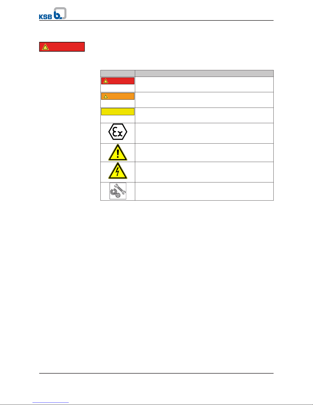
Table 3: Definition of safety symbols/markings
Symbol Description
!
DANGER
DANGER
This signal word indicates a high-risk hazard which, if not avoided,
will result in death or serious injury.
!
WARNING
WARNING
This signal word indicates a medium-risk hazard which, if not
avoided, could result in death or serious injury.
CAUTION
CAUTION
This signal word indicates a hazard which, if not avoided, could
result in damage to the machine and its functions.
Explosion protection
This symbol identifies information about avoiding explosions in
potentially explosive atmospheres in accordance with EC Directive
2014/34/EU (ATEX).
General hazard
In conjunction with one of the signal words this symbol indicates a
hazard which will or could result in death or serious injury.
Electrical hazard
In conjunction with one of the signal words this symbol indicates a
hazard involving electrical voltage and identifies information about
protection against electrical voltage.
Machine damage
In conjunction with the signal word CAUTION this symbol indicates
a hazard for the machine and its functions.
2.2 General
This manual contains general installation, operating and maintenance instructions
that must be observed to ensure safe pump operation and prevent personal injury
and damage to property.
The safety information in all sections of this manual must be complied with.
This manual must be read and completely understood by the specialist personnel/
operators responsible prior to installation and commissioning.
The contents of this manual must be available to the specialist personnel at the site
at all times.
Information attached directly to the pump must always be complied with and be
kept in a perfectly legible condition at all times. This applies to, for example:
▪ Arrow indicating the direction of rotation
▪ Markings for connections
▪ Name plate
The operator is responsible for ensuring compliance with all local regulations not
taken into account in this manual.
2.3 Intended use
▪ The pump (set) must only be operated within the operating limits described in
the other applicable documents. (⇨ Section 1.4 Page 6)
▪ Only operate pumps/pump sets which are in perfect technical condition.
▪ Do not operate the pump (set) in partially assembled condition.
▪ Only use the pump to handle the fluids described in the data sheet or product
literature of the pump model or variant.
!
DANGER
2 Safety
8 of 94
Omega / Omega V
Page 9

▪ Never operate the pump without the fluid to be handled.
▪ Observe the minimum flow rates indicated in the data sheet or product literature
(to prevent overheating, bearing damage, etc).
▪ Observe the maximum flow rates indicated in the data sheet or product
literature (to prevent overheating, mechanical seal damage, cavitation damage,
bearing damage, etc).
▪ Do not throttle the flow rate on the suction side of the pump (to prevent
cavitation damage).
▪ Consult the manufacturer about any use or mode of operation not described in
the data sheet or product literature.
Prevention of foreseeable misuse
▪ Never open the discharge-side shut-off elements further than permitted.
– The maximum flow rates specified in the product literature or data sheet
would be exceeded.
– Risk of cavitation damage
▪ Never exceed the permissible operating limits specified in the data sheet or
product literature regarding pressure, temperature, etc.
▪ Observe all safety information and instructions in this manual.
2.4 Personnel qualification and training
All personnel involved must be fully qualified to transport, install, operate, maintain
and inspect the machinery this manual refers to.
The responsibilities, competence and supervision of all personnel involved in
transport, installation, operation, maintenance and inspection must be clearly
defined by the operator.
Deficits in knowledge must be rectified by means of training and instruction
provided by sufficiently trained specialist personnel. If required, the operator can
commission the manufacturer/supplier to train the personnel.
Training on the pump (set) must always be supervised by technical specialist
personnel.
2.5 Consequences and risks caused by non-compliance with this manual
▪ Non-compliance with this operating manual will lead to forfeiture of warranty
cover and of any and all rights to claims for damages.
▪ Non-compliance can, for example, have the following consequences:
– Hazards to persons due to electrical, thermal, mechanical and chemical
effects and explosions
– Failure of important product functions
– Failure of prescribed maintenance and servicing practices
– Hazard to the environment due to leakage of hazardous substances
2.6 Safety awareness
In addition to the safety information contained in this manual and the intended use,
the following safety regulations shall be complied with:
▪ Accident prevention, health and safety regulations
▪ Explosion protection regulations
▪ Safety regulations for handling hazardous substances
▪ Applicable standards, directives and laws
2 Safety
Omega / Omega V
9 of 94
Page 10
2.7 Safety information for the operator/user
▪ The operator shall fit contact guards for hot, cold and moving parts and check
that the guards function properly.
▪ Do not remove any contact guards during operation.
▪ Provide the personnel with protective equipment and make sure it is used.
▪ Contain leakages (e.g. at the shaft seal) of hazardous fluids handled (e.g.
explosive, toxic, hot) so as to avoid any danger to persons and the environment.
Adhere to all relevant laws.
▪ Eliminate all electrical hazards. (In this respect refer to the applicable national
safety regulations and/or regulations issued by the local energy supply
companies.)
▪ If shutting down the pump does not increase potential risk, fit an emergency-
stop control device in the immediate vicinity of the pump (set) during pump set
installation.
2.8 Safety information for maintenance, inspection and installation
▪ Modifications or alterations of the pump are only permitted with the
manufacturer's prior consent.
▪ Use only original spare parts or parts authorised by the manufacturer. The use of
other parts can invalidate any liability of the manufacturer for resulting damage.
▪ The operator ensures that maintenance, inspection and installation is performed
by authorised, qualified specialist personnel who are thoroughly familiar with
the manual.
▪ Only carry out work on the pump (set) during standstill of the pump.
▪ The pump casing must have cooled down to ambient temperature.
▪ Pump pressure must have been released and the pump must have been drained.
▪ When taking the pump set out of service always adhere to the procedure
described in the manual. (⇨ Section 6.3 Page 46)
▪ Decontaminate pumps which handle fluids posing a health hazard. (⇨ Section 7.3
Page 53)
▪ As soon as the work has been completed, re-install and/or re-activate any safety-
relevant and protective devices. Before returning the product to service, observe
all instructions on commissioning. (⇨ Section 6.1 Page 40)
2.9 Unauthorised modes of operation
Never operate the pump (set) outside the limits stated in the data sheet and in this
manual.
The warranty relating to the operating reliability and safety of the supplied pump
(set) is only valid if the equipment is used in accordance with its intended use.
(⇨ Section 2.3 Page 8)
2.10 Explosion protection
Always observe the information on explosion protection given in this section when
operating the product in potentially explosive atmospheres.
Only pumps/pump sets marked as explosion-proof and identified as such in the data
sheet may be used in potentially explosive atmospheres.
Special conditions apply to the operation of explosion-proof pump sets to EU
Directive 2014/34/EU (ATEX).
The explosion-proof status of the pump set is only assured if the pump set is used in
accordance with its intended use.
Never operate the pump set outside the limits stated in the data sheet and on the
name plate.
!
DANGER
2 Safety
10 of 94
Omega / Omega V
Page 11
Prevent impermissible modes of operation at all times.
For information on application options of individual components (if any) in
potentially explosive atmospheres, refer to the manufacturer's product literature.
2.10.1 Marking
The marking on the pump refers to the pump part only.
Example of such marking: II 2 G c TX
Refer to the Temperature Limits table for the temperatures permitted for the
individual pump variants. (⇨ Section 2.10.2 Page 11)
An EC manufacturer's declaration is required for the shaft coupling; the shaft
coupling must be marked accordingly.
The motor must be considered separately.
2.10.2 Temperature limits
In normal pump operation, the highest temperatures are to be expected at the
surface of the pump casing, at the shaft seal and in the bearing areas.
The surface temperature at the pump casing corresponds to the temperature of the
fluid handled. If the pump is heated, the operator of the system is responsible for
observing the specified temperature class and fluid temperature (operating
temperature).
The table below lists the temperature classes and the resulting theoretical
temperature limits of the fluid handled (a possible temperature rise in the shaft seal
area has already been taken into account).
The temperature class specifies the maximum permissible temperature at the surface
of the pump set during operation. For the permissible operating temperature of the
pump in question refer to the data sheet.
Table 4: Temperature limits
Temperature class to EN 13463-1
Maximum permissible fluid
temperature
T1 Maximum 140 °C
T2 Maximum 140 °C
T3 Maximum 140 °C
T4 80 °C
T5 45 °C
T6 Impermissible
Based on an ambient temperature of 40 °C and proper maintenance and operation,
compliance with temperature class T5 is warranted in the area of the rolling element
bearings. If the ambient temperature exceeds 40 °C, contact the manufacturer.
2.10.3 Repair
Special regulations apply to repair work on explosion-proof pumps. Modifications or
alterations of the pump set can affect explosion protection and are only permitted
after consultation with the manufacturer.
Repair work at the flameproof joints must only be performed in accordance with the
manufacturer's instructions. Repair to the values in tables 1 and 2 of EN 60079-1 is
not permitted.
Pump
Shaft coupling
Motor
Temperature class T5
2 Safety
Omega / Omega V
11 of 94
Page 12

3 Transport/Temporary Storage/Disposal
3.1 Checking the condition upon delivery
1. On transfer of goods, check each packaging unit for damage.
2. In the event of in-transit damage, assess the exact damage, document it and
notify KSB or the supplying dealer (as applicable) and the insurer about the
damage in writing immediately.
3.2 Transport
DANGER
Lifting lugs of pump/motor/base frame overloaded
Danger to life from falling parts!
▷ Never transport the pump set components (pump/motor/base frame) in any way
other than as described in the Transport section.
▷ Refer to the weights of the individual components stated in the manufacturer's
product literature.
DANGER
The pump (set) could slip out of the suspension arrangement
Danger to life from falling parts!
▷ Always transport the pump (set) in the specified position.
▷ Never attach the suspension arrangement to the free shaft end or the motor
eyebolt.
▷ Give due attention to the weight data and the centre of gravity.
▷ Observe the applicable local health and safety regulations.
▷ Use suitable, permitted lifting accessories, e.g. self-tightening lifting tongs.
For transporting the motor, observe the motor supplier's product literature!
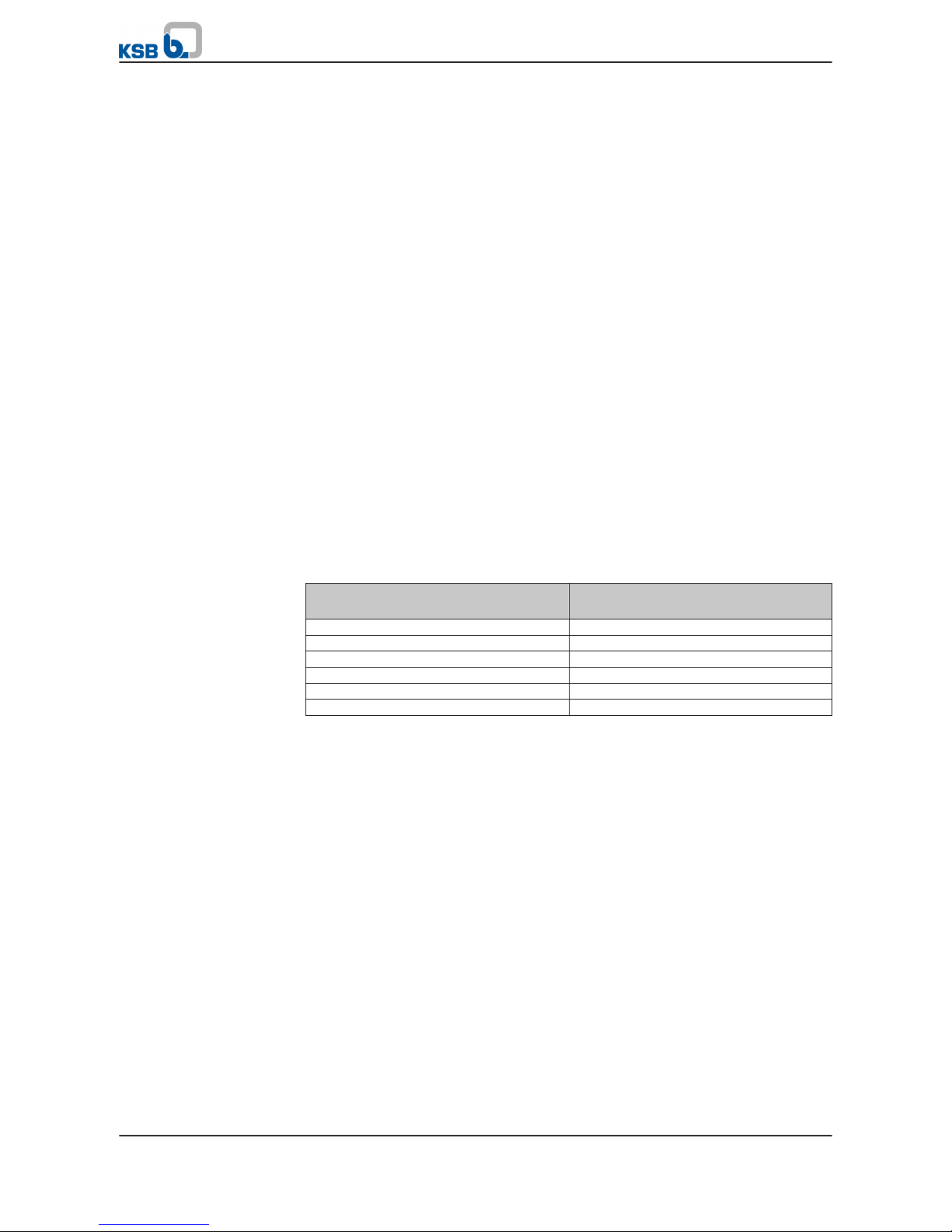
To transport the pump/pump set suspend it from the lifting tackle as shown.
Fig. 1: The angle of pull must not be greater than 90°!
3 Transport/Temporary Storage/Disposal
12 of 94
Omega / Omega V
Page 13
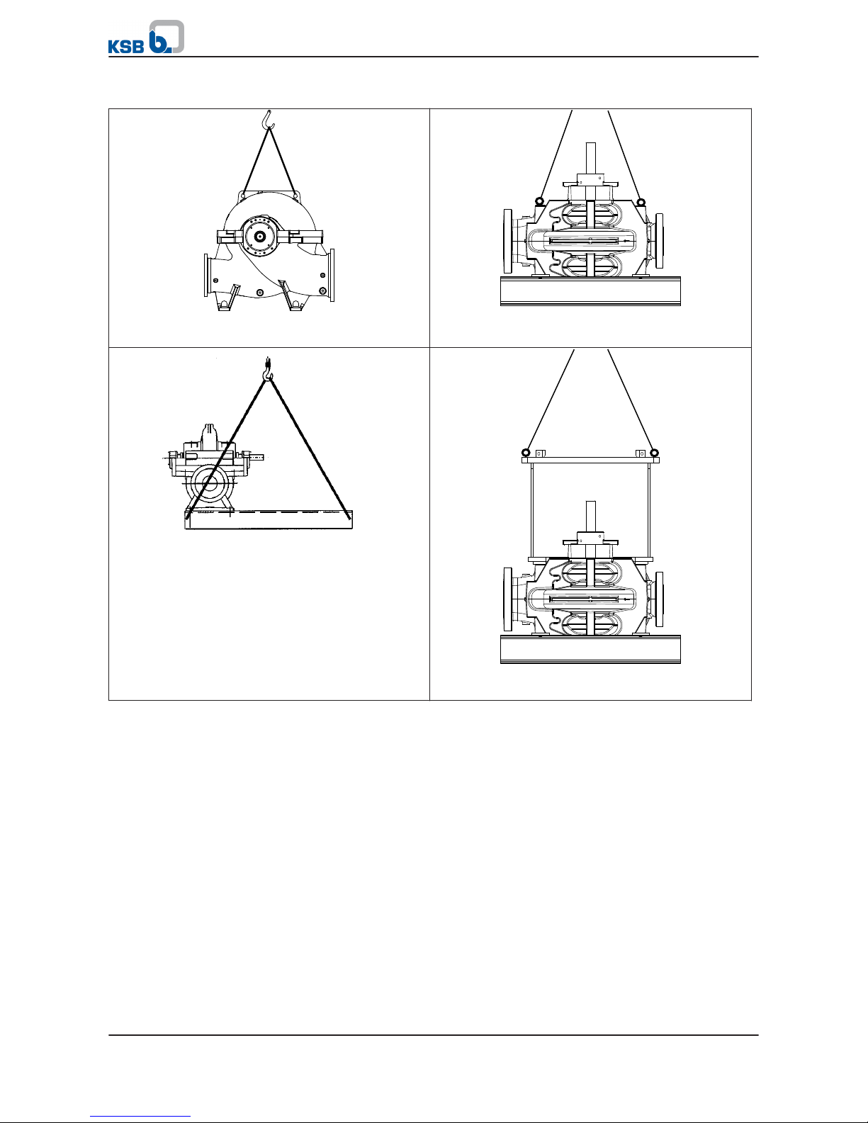
Table 5: Transport options
Transporting the pump horizontally
(figure 0)
Transporting the pump vertically
(figure 0 or installation type DJ)
Transporting the pump with base frame (figure 0)
▪ Motor size 315 and larger
▪ Total weight (of the pump set) more than 1500 kg
Transporting the pump vertically
(installation types DB and DK)
3 Transport/Temporary Storage/Disposal
Omega / Omega V
13 of 94
Page 14
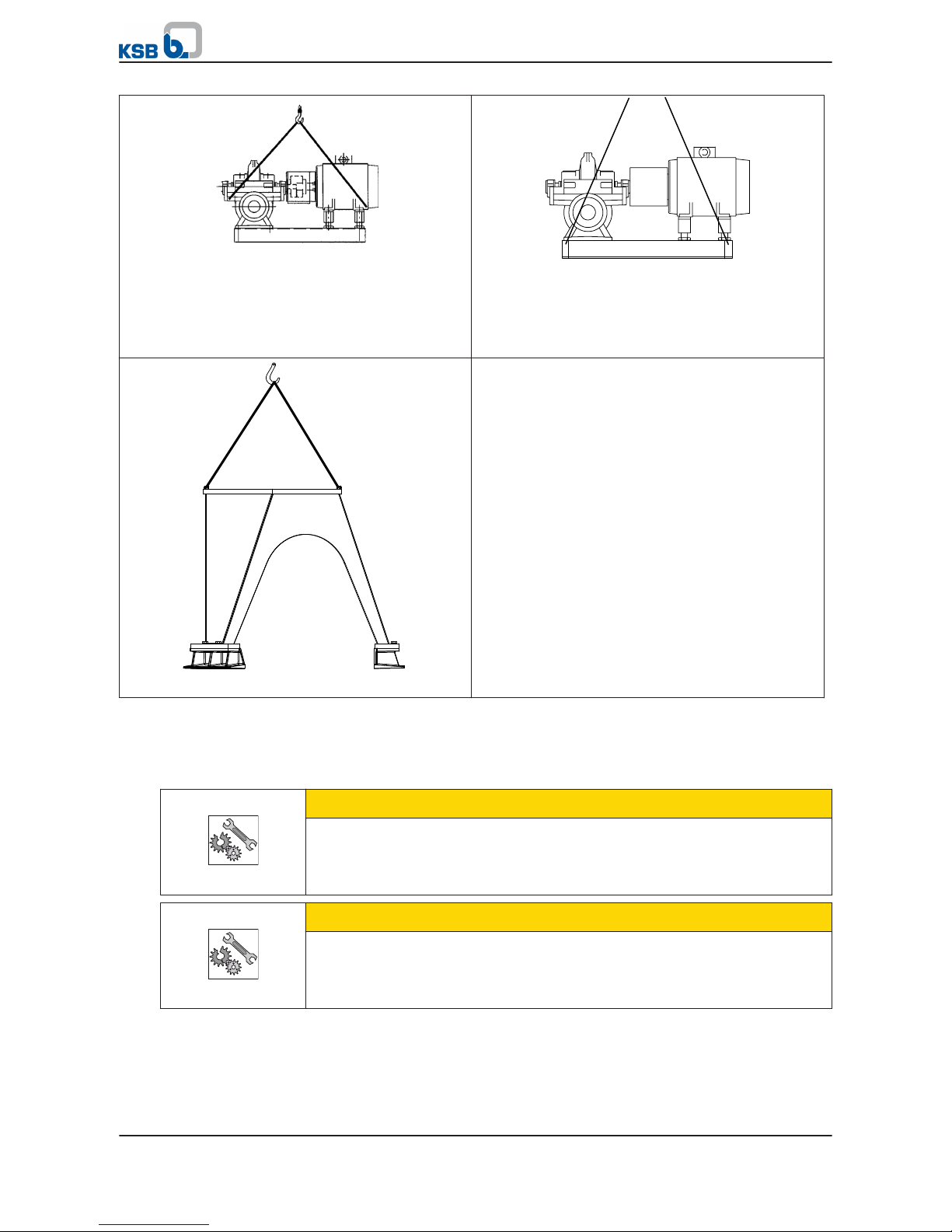
Transporting the pump set on the base frame
(installation type 3E)
▪ Up to motor size 280 (IEC standard)
▪ Up to a total weight (of the pump set) of 1500 kg
Transporting the pump set on the base frame
(installation type 3E)
Use the hooks welded to the baseplate!
▪ Up to motor size 280 (IEC standard)
▪ Up to a total weight (of the pump set) of 1500 kg
Transporting the base frame (installation type DP)
3.3 Storage/preservation
If commissioning is to take place some time after delivery, we recommend that the
following measures be taken:
CAUTION
Damage during storage by humidity, dirt, or vermin
Corrosion/contamination of the pump (set)!
▷ For outdoor storage cover the packed or unpacked pump (set) and accessories
with waterproof material.
CAUTION
Wet, contaminated or damaged openings and connections
Leakage or damage to the pump!
▷ Clean and cover pump openings and connections as required prior to putting
the pump into storage.
3 Transport/Temporary Storage/Disposal
14 of 94
Omega / Omega V
Page 15
CAUTION
Bearings in the same position for a prolonged period of time
Damage to the rolling element bearings!
▷ Rotate the shaft by hand once a month with suitable tools.
▷ Store the pump in a vibration-free room.
CAUTION
Pump stored too long or incorrectly
Damage to the pump!
▷ Check especially the rolling element bearings and the lubricant. If any damage
is suspected, replace the rolling element bearings.
▪ Store the pump and supplied components under dry, vibration-free conditions, if
possible in their original packaging.
▪ The ambient temperatures for transport and storage must not be below -20 °C or
above 60 °C.
1. Manually rotate the pump shaft once a month with a suitable tool.
2. Spray the preservative through the suction and discharge nozzles.
It is advisable to then close the pump nozzles (e.g. with plastic caps or similar).
NOTE
Observe the manufacturer's instructions for application/removal of the preservative.
3.4 Return to supplier
1. Drain the pump as per operating instructions. (⇨ Section 7.3 Page 53)
2. Always flush and clean the pump, particularly if it has been used for handling
noxious, explosive, hot or other hazardous fluids.
3. If the pump set has handled fluids whose residues could lead to corrosion
damage in the presence of atmospheric humidity or could ignite upon contact
with oxygen, the pump set must also be neutralised, and anhydrous inert gas
must be blown through the pump to ensure drying.
4. Always complete and enclose a certificate of decontamination when returning
the pump (set).
Always indicate any safety and decontamination measures taken. (⇨ Section 11
Page 91)
NOTE
If required, a blank certificate of decontamination can be downloaded from the
KSB web site at: www.ksb.com/certificate_of_decontamination
3.5 Disposal
WARNING
Fluids, consumables and supplies which are hot and/or pose a health hazard
Hazard to persons and the environment!
▷ Collect and properly dispose of flushing fluid and any residues of the fluid
handled.
▷ Wear safety clothing and a protective mask, if required.
▷ Observe all legal regulations on the disposal of fluids posing a health hazard.
3 Transport/Temporary Storage/Disposal
Omega / Omega V
15 of 94
Page 16

1. Dismantle the pump (set).
Collect greases and other lubricants during dismantling.
2. Separate and sort the pump materials, e.g. by:
- Metals
- Plastics
- Electronic waste
- Greases and other lubricants
3. Dispose of materials in accordance with local regulations or in another
controlled manner.
3 Transport/Temporary Storage/Disposal
16 of 94
Omega / Omega V
Page 17
4 Description of the Pump (Set)
4.1 General description
▪ Volute casing pump installed in a horizontal or vertical position
▪ Volute casing pump with double-entry radial impeller
Pump for use in water works, irrigation and drainage pumping systems, power
stations and industrial water supply.
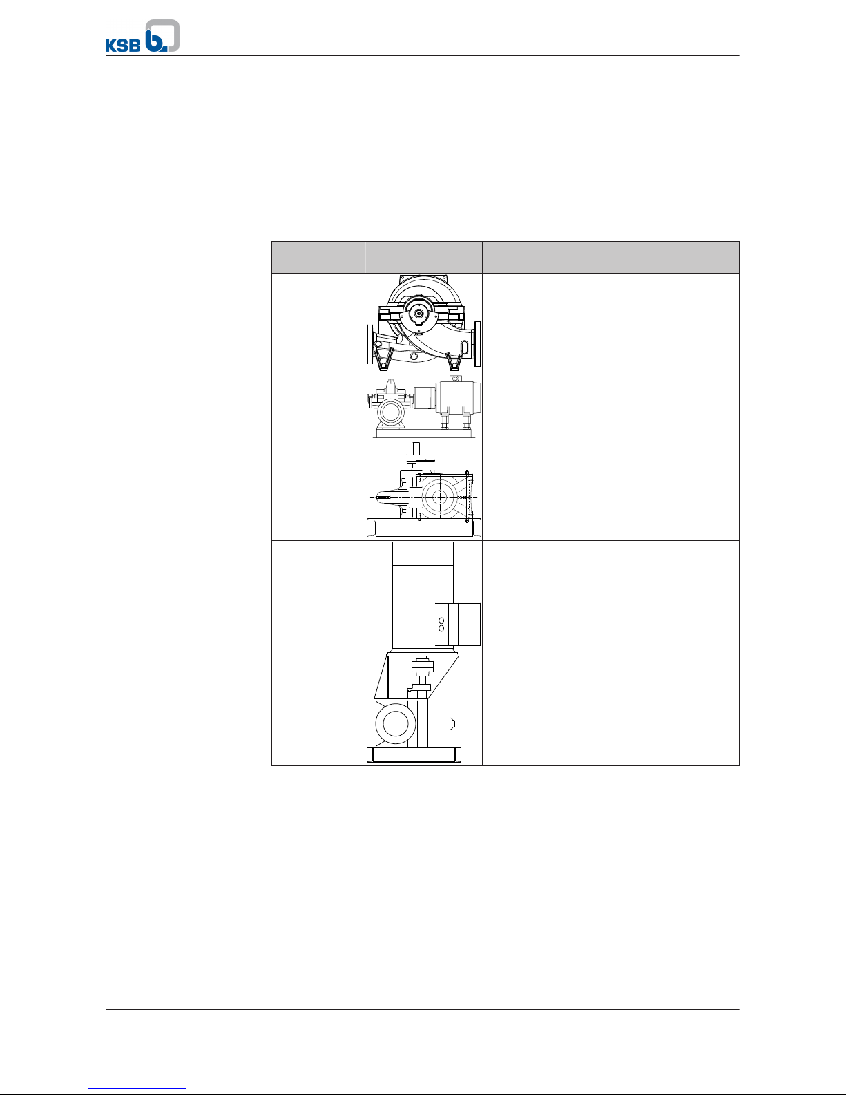
Table 6: Installation types
Installation
type
Illustration Description
Figure 0 Bare shaft pump
Figure 3E Pump and drive on a common base frame
Horizontal installation, direct coupling
Figure DJ Pump on its own base frame;
drive on a different construction level
Vertical installation
Figure DB Pump on base frame and drive on drive
lantern
Vertical installation
4 Description of the Pump (Set)
Omega / Omega V
17 of 94
Page 18
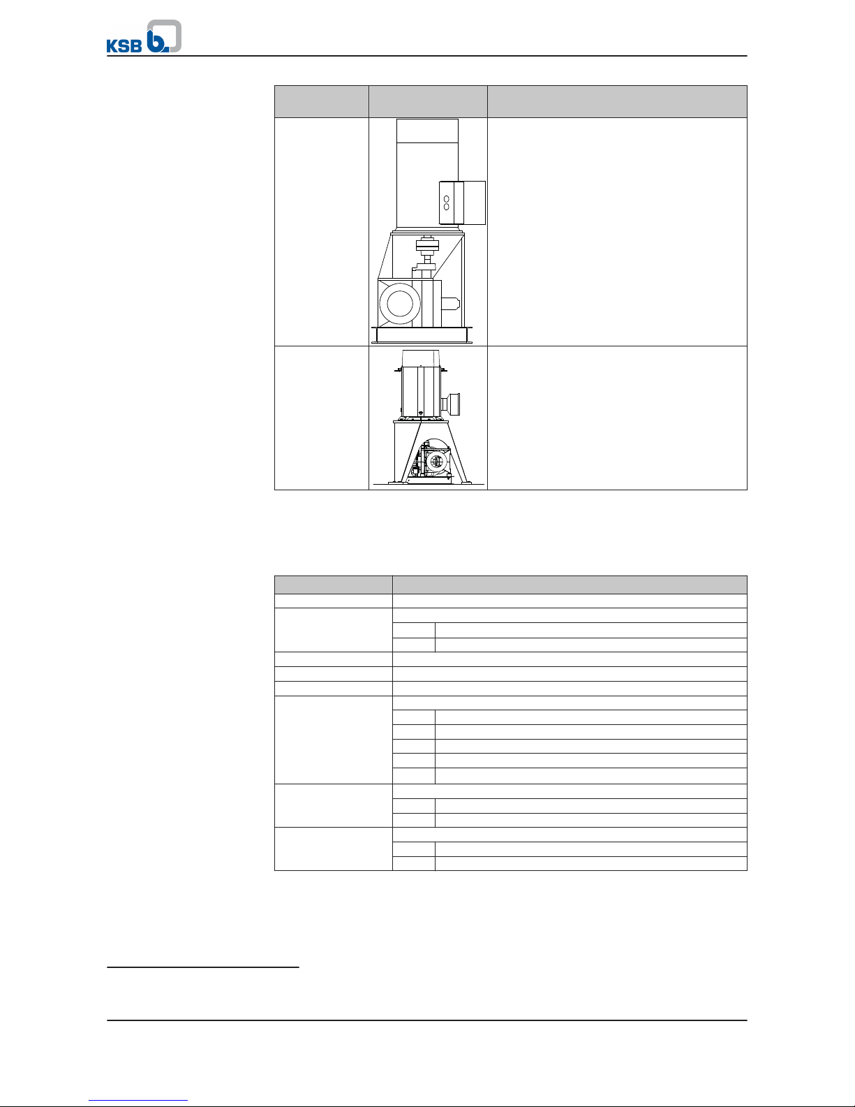
Installation
type
Illustration Description
Figure DK Pump on base frame and drive on drive
lantern with support
Vertical installation
Figure DP Pump on base frame, drive on support frame
4.2 Designation
Example: Omega V 150 - 460 A GB P M
Table 7: Designation key
Code Description
Omega Type series
V Design
2)
Horizontal installation
V Vertical installation
150 Nominal discharge nozzle diameter [mm]
460 Nominal impeller diameter [mm]
A Impeller type
GB Material variant
GB Grey cast iron / bronze
GC Grey cast iron / chrome steel
SB Nodular cast iron / bronze
SC Nodular cast iron / chrome steel
DD35Duplex stainless steel / duplex stainless steel
P Shaft seal
P Gland packing
G Mechanical seal
M Bearing lubrication
F Grease
M Fluid handled
2)
Blank
4 Description of the Pump (Set)
18 of 94
Omega / Omega V
Page 19
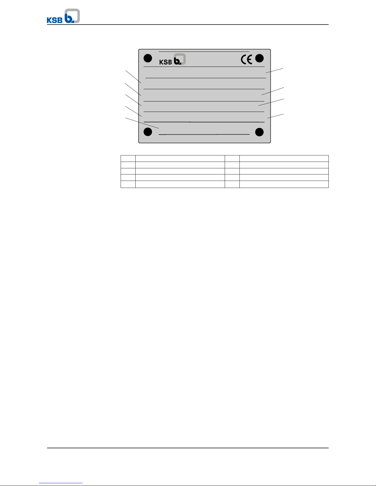
4.3 Name plate
Omega 250 - 600 A
P-No. 9971423078 / 000100
Q 1050 m3/h H 120 m
n 1475 1/min SNr. 24 15 26
Aktiengesellschaft
Johann-Klein-Straße 9
D-67227 Frankenthal
Mat.-No. 01 111 383 ZN 3804 - D 74 x 105
2016
Gew. 1090 kg
1
2
5
4
3
9
8
7
6
Fig. 2: Name plate (example)
1
Designation of the pump set 2 Order number
3 Flow rate 4 Speed
5 Weight of Fig. 0 pump 6 Year of supply
7 Order item number 8 Head
9 Series number
4.4 Design details
Design
▪ Volute casing pump
▪ Horizontal/vertical installation
▪ Single-stage
▪ Nominal diameter of the discharge nozzles: 80 mm to 350 mm
Pump casing
▪ Axially split volute casing
▪ Volute casing with integrally cast pump feet
▪ Replaceable casing wear rings
▪ Mating dimensions to EN or ASME
Impeller type
▪ Double-entry radial impeller
Optionally with impeller wear rings
Pump shaft
▪ Completely dry shaft for design with rolling element bearings
▪ Shaft protecting sleeves in the seal area
Shaft seal
▪ Gland packing
▪ Mechanical seal
Bearings
For horizontal installation:
▪ Rolling element bearings, greased for life
For vertical installation:
▪ Product-lubricated plain bearing at the bottom / rolling element bearing,
greased for life, on top
4 Description of the Pump (Set)
Omega / Omega V
19 of 94
Page 20
4.5 Configuration and function
6
7
2
3
4
8
9
10
5
1
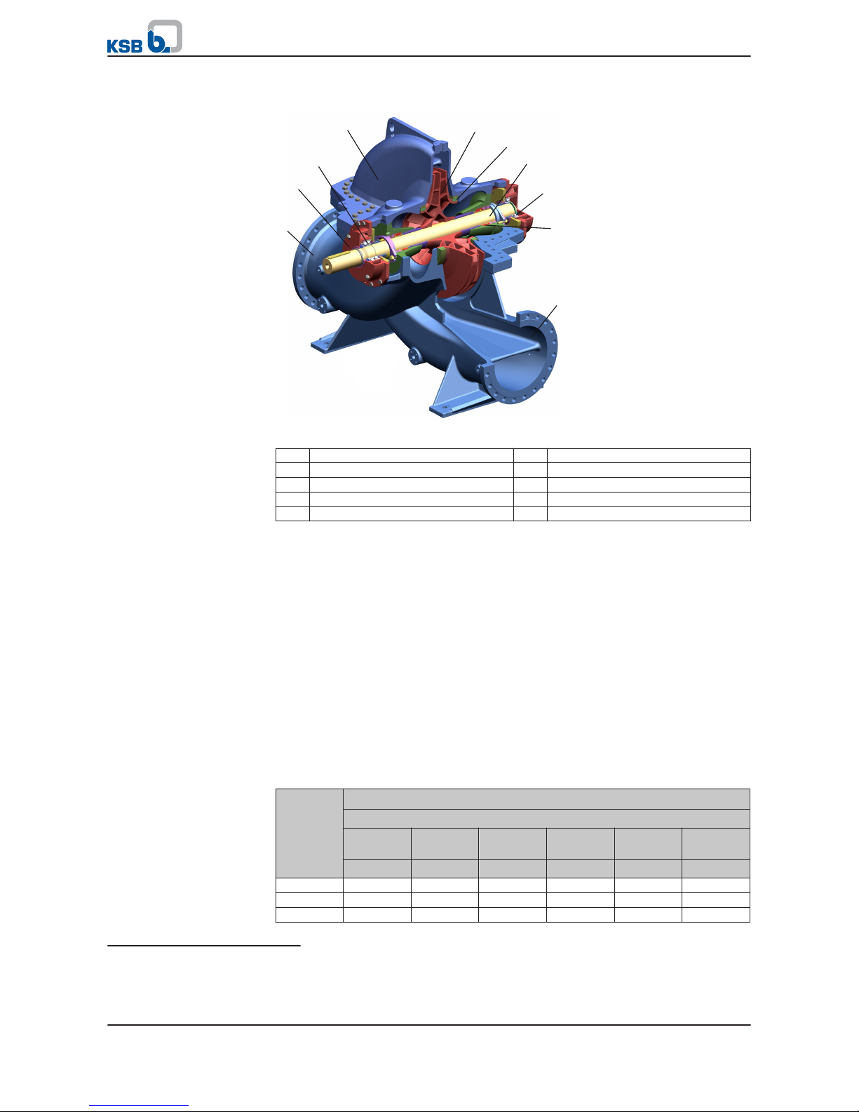
Fig. 3: Sectional drawing
1
Suction nozzle 2 Bearing housing
3 Rolling element bearing 4 Volute casing
5 Impeller 6 Clearance gap
7 Shaft 8 Rolling element bearing
9 Shaft seal 10 Discharge nozzle
The pump is designed with a tangential fluid inlet and a tangential fluid outlet. The
hydraulic system runs in its own bearings and is connected to the motor by a shaft
coupling.
The fluid enters the pump tangentially via the suction nozzle (1) and is accelerated
outward by the rotating impeller (5). In the flow passage of the pump casing the
kinetic energy of the fluid is converted into pressure energy. The fluid is pumped to
the discharge nozzle (10), where it leaves the pump. The clearance gap (6) prevents
any fluid from flowing back from the casing to the suction nozzle. The shaft (7)
enters the hydraulic system through the volute casing (4). The shaft passage through
the sealing housing is sealed to atmosphere with a shaft seal (9). The shaft runs in
rolling element bearings (3 and 8) located in a bearing housing (2) which is
connected to the volute casing (4).
The pump is sealed by a shaft seal (standardised mechanical seal or gland packing).
4.6 Noise characteristics
Table 8: Surface sound pressure level L
pA
3)
depending on the rotational speed
Rated
power
PN [kW]
Surface sound pressure level L
pA
3)
Pump
3500 rpm 2900 rpm 1750 rpm 1450 rpm 1160 / 870
rpm
960 / 750
rpm
[dB (A)] [dB (A)] [dB (A)] [dB (A)] [dB (A)] [dB (A)]
10 69,5 69,0 67,4 67,0 65,6 64,6
15 70,8 70,3 68,7 68,3 66,9 65,9
20 71,8 71,3 69,7 69,3 67,8 66,8
Design
Function
Sealing
Pump
3)
Spatial average; as per ISO 3744 and EN 12639; valid for pump operation in the Q/Qopt = 0.8 - 1.1 range and for noncavitating operation. If noise levels are to be guaranteed: Add +3 dB for measuring and constructional tolerance. The
values indicated do not apply to operation on a frequency inverter.
4 Description of the Pump (Set)
20 of 94
Omega / Omega V
Page 21

Rated
power
PN [kW]
Surface sound pressure level L
pA
3)
Pump
3500 rpm 2900 rpm 1750 rpm 1450 rpm 1160 / 870
rpm
960 / 750
rpm
[dB (A)] [dB (A)] [dB (A)] [dB (A)] [dB (A)] [dB (A)]
30 73,1 72,7 71,0 70,6 69,1 68,2
40 74,1 73,6 71,9 71,5 70,1 69,1
50 74,8 74,3 72,7 72,2 70,8 69,8
60 75,4 75,0 73,3 72,8 71,4 70,4
70 75,9 75,5 73,8 73,3 71,9 70,9
80 76,4 75,9 74,2 73,8 72,3 71,3
90 76,8 76,3 74,6 74,2 72,7 71,7
100 77,1 76,7 74,9 74,5 73,1 72,1
150 78,5 78,0 76,3 75,8 74,4 73,4
200 79,4 79,0 77,2 76,8 75,3 74,3
250 80,2 79,7 77,9 77,5 76,0 75,0
300 80,8 80,3 78,5 78,1 76,6 75,6
350 81,3 80,8 79,0 78,6 77,1 76,1
400 82,0 81,5 79,8 79,3 77,8 76,8
450 82,1 81,6 79,9 79,4 77,9 76,9
500 82,5 82,0 80,2 79,7 78,3 77,3
600 83,1 82,6 80,8 80,3 78,9 77,8
700 83,6 83,1 81,3 80,8 79,4 78,3
800 84,0 83,6 81,7 81,3 79,8 78,8
900 84,4 84,0 82,1 81,7 80,2 79,2
1000 84,8 84,3 82,5 82,0 80,5 79,5
Table 9: Surface sound pressure level L
pA
4)
depending on the rotational speed
Rated
power
PN [kW]
Surface sound pressure level L
pA
4)
Pump set
3500 rpm 2900 rpm 1750 rpm 1450 rpm 1160 / 870
rpm
960 / 750
rpm
[dB (A)] [dB (A)] [dB (A)] [dB (A)] [dB (A)] [dB (A)]
10 74,5 74,0 70,0 69,0 66,4 64,6
15 75,7 75,2 71,4 70,5 67,9 66,2
20 76,6 76,1 72,4 71,5 69,0 67,4
30 77,8 77,3 73,8 72,9 70,6 69,0
40 78,7 78,2 74,8 74,0 71,7 70,1
50 79,4 78,9 75,6 74,8 72,6 71,0
60 79,9 79,4 76,3 75,4 73,3 71,8
70 80,4 79,9 76,8 76,0 73,8 72,4
80 80,8 80,3 77,3 76,5 74,4 72,9
90 81,2 80,7 77,7 76,9 74,8 73,4
100 81,5 81,0 78,0 77,2 75,2 73,8
150 82,7 82,2 79,4 78,7 76,8 75,4
200 83,6 83,1 80,4 79,7 77,9 76,6
250 84,3 83,8 81,2 80,5 78,7 77,5
300 84,8 84,3 81,8 81,2 79,4 78,2
350 85,3 84,8 82,4 81,7 80,0 78,8
400 85,7 85,2 82,8 82,2 80,5 79,3
450 86,0 85,6 83,2 82,6 81,0 79,8
500 86,4 85,9 83,6 83,0 81,4 80,2
600 86,9 86,4 84,2 83,7 82,1 81,0
700 87,4 86,9 84,8 84,2 82,7 81,6
800 87,8 87,3 85,2 84,7 83,2 82,1
Pump set
4)
Spatial average; as per ISO 3744 and EN 12639; valid for pump operation in the Q/Qopt = 0.8 - 1.1 range and for noncavitating operation. If noise levels are to be guaranteed: Add +3 dB for measuring and constructional tolerance. The
values indicated do not apply to operation on a frequency inverter.
4 Description of the Pump (Set)
Omega / Omega V
21 of 94
Page 22
Rated
power
PN [kW]
Surface sound pressure level L
pA
4)
Pump set
3500 rpm 2900 rpm 1750 rpm 1450 rpm 1160 / 870
rpm
960 / 750
rpm
[dB (A)] [dB (A)] [dB (A)] [dB (A)] [dB (A)] [dB (A)]
900 88,2 87,7 85,7 85,1 83,6 82,6
1000 88,5 88,0 86,0 85,5 84,0 83,0
4.7 Scope of supply
Depending on the model, the following items are included in the scope of supply:
▪ Pump
▪ Drive
▪ Baseplate
▪ Coupling, coupling guard
▪ Universal-joint shaft
▪ Fasteners for pump and base frame
Optional accessories:
▪ Vibration monitoring
▪ Pt100 temperature sensor
▪ Pressure gauge
▪ Measuring nipple for shock pulse measurement
▪ Cyclone
4.8 Dimensions and weights
For dimensions and weights please refer to the data sheet of the pump (set).
▪ Pump weight: See name plate of the pump.
▪ Motor weight: See motor product literature.
▪ Weight of the shipping unit base frame with pump: See weight indicated on the
base frame.
▪ Weight of the shipping unit base frame with pump and motor: See weight
indicated on the base frame.
NOTE
Some individual components weigh more than 25 kg. Observe the weights
indicated.( (⇨ Section 9.1 Page 74) or other applicable documents)
4 Description of the Pump (Set)
22 of 94
Omega / Omega V
Page 23
5 Installation at Site
5.1 Safety regulations
For all work involving assembly, reassembly and installation, observe the following
safety information:
DANGER
Improper installation in potentially explosive atmospheres
Explosion hazard!
Damage to the pump set!
▷ Comply with the applicable local explosion protection regulations.
▷ Observe the information in the data sheet and on the name plates of pump and
motor.
DANGER
Improper transport
Risk of injury from lifting heavy components!
▷ Select lifting accessories which are suitable for the component weight.
▷ Always use the attachment points provided for the lifting accessories.
▷ Comply with the applicable health and safety regulations.
5.2 Checks to be carried out prior to installation
Place of installation
WARNING
Installation on mounting surface which is unsecured and cannot support the load
Personal injury and damage to property!
▷ Use a concrete of compressive strength class C12/15 which meets the
requirements of exposure class XC1 to EN 206-1.
▷ The mounting surface must have set and must be completely horizontal and
even.
▷ Observe the weights indicated.
1. Check the structural requirements.
All structural work required must have been prepared in accordance with the
dimensions stated in the outline drawing/general arrangement drawing.
5.3 Installing the pump set
WARNING
Hands or foreign objects inside the pump casing
Risk of injuries, damage to the pump!
▷ Check that the inside of the pump is free from any foreign objects. Remove any
foreign objects.
▷ Never insert your hands or any other objects into the pump, if the pump set has
not been disconnected from the power supply and secured against
unintentional start-up.
Depending on the type of installation, several instructions need to be carried out as
applicable:
▪ Prepare and install the base frame/support frame.
▪ Install the pump and motor on the prepared base frame/support frame.
5 Installation at Site
Omega / Omega V
23 of 94
Page 24
▪ Check the alignment of pump and motor.
▪ Align the pump with the piping.
▪ Install and align the coupling.
▪ Connect the piping.
▪ Perform precision alignment of pump and motor.
▪ Remove any transport locks.
5.3.1 Type of installation 3E
DANGER
The pump or individual components could slip out of the suspension arrangement
Danger to life from falling parts!
▷ Always transport the pump or components in the specified position.
▷ Never attach the suspension arrangement to the free shaft end of the pump.
▷ Refer to the weights indicated for the individual components.
▷ Observe the applicable local health and safety regulations.
▷ Use suitable, permitted lifting accessories.
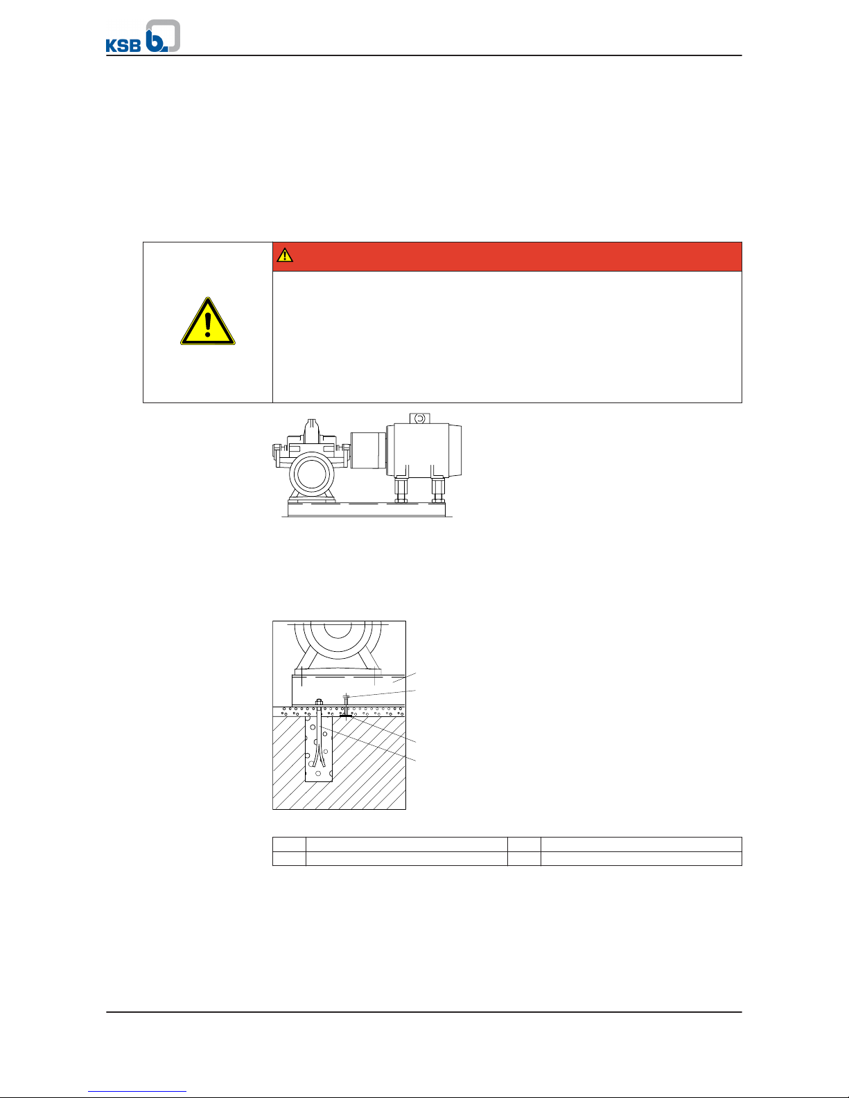
Fig. 4: 3E installation — pump and motor on a common base frame
✓ The relevant general arrangement drawing is available.
✓ The foundation has the required strength and characteristics.
✓ The foundation has been prepared in accordance with the dimensions given in
the outline drawing.
1
2
3
4
Fig. 5: Installation drawing
1
Base frame, part No. 891 2 Adjusting screw, part No. 901.05
3 Shim, part No. 89-4.03 4 Foundation bolt, part No. 900.01
1. Screw adjusting screws (2) into the threaded holes provided in the base frame
(1).
2. Insert the foundation bolts (4) into the drilled holes of the base frame (1).
3. Place the shim (3) next to the holes for the foundation bolts (4) in accordance
with the general arrangement drawing.
4. Align the pump with the piping.
5 Installation at Site
24 of 94
Omega / Omega V
Page 25
5. Place the base frame (1) with the inserted foundation bolts (4) and the screwedin adjusting screws (2) on the shims (3). Use the adjusting screws to align the
base frame.
6. Grout the holes for the foundation bolts with a quick-setting, low-shrinkage
concrete mixture5).
7. When the concrete has set, tighten the foundation bolts evenly until no
clearance remains between the nuts and the base frame.
8. Grout the base frame with a quick-setting, low-shrinkage concrete mixture5).
Make sure that the base frame is completely grouted and that no cavities
remain.
9. When the concrete has set, tighten the foundation bolts.
10. Lift the motor (if not already mounted) onto the base frame with suitable
lifting equipment. Align the shafts with each other. Mount the motor as
described in the motor manufacturer's operating manual.
11. Connect the piping to the pump without transmitting any stresses or strains.
(⇨ Section 5.4 Page 30)
12. Align the coupling as described in the coupling manufacturer's operating
manual.
5.3.2
Type of installation DJ
DANGER
The pump or individual components could slip out of the suspension arrangement
Danger to life from falling parts!
▷ Always transport the pump or components in the specified position.
▷ Never attach the suspension arrangement to the free shaft end of the pump.
▷ Refer to the weights indicated for the individual components.
▷ Observe the applicable local health and safety regulations.
▷ Use suitable, permitted lifting accessories.
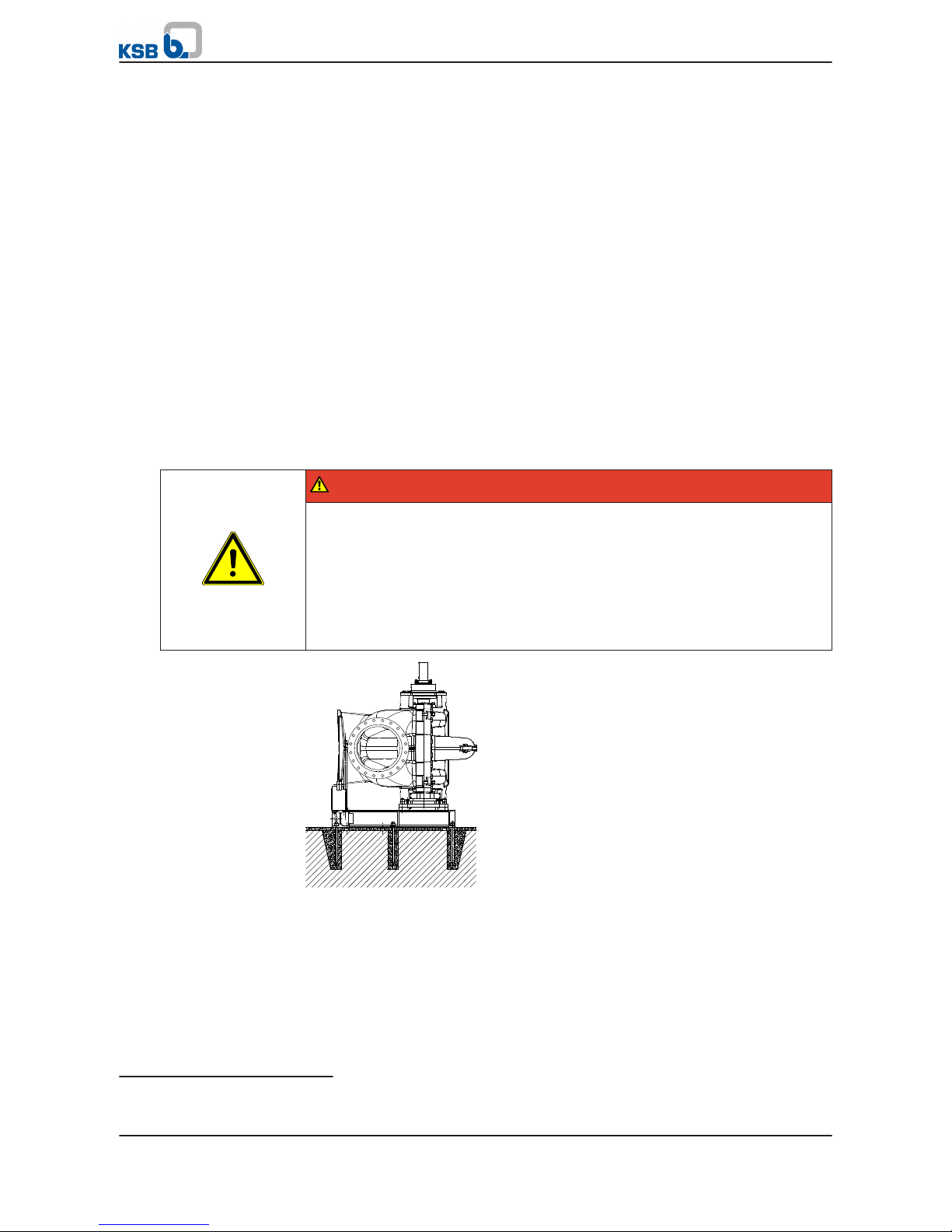
Fig. 6: Pump on its own foot (baseplate), drive on a different construction level
✓ The relevant general arrangement drawing is available.
✓ The foundation has the required strength and characteristics.
✓ The foundation has been prepared in accordance with the dimensions given in
the general arrangement drawing.
✓ The motor is installed on a separate base frame which is arranged on a higher
level in the building in accordance with the motor manufacturer's operating
instructions.
5)
Minimum strength class C2
5 Installation at Site
Omega / Omega V
25 of 94
Page 26
1
2
3
4
5
6
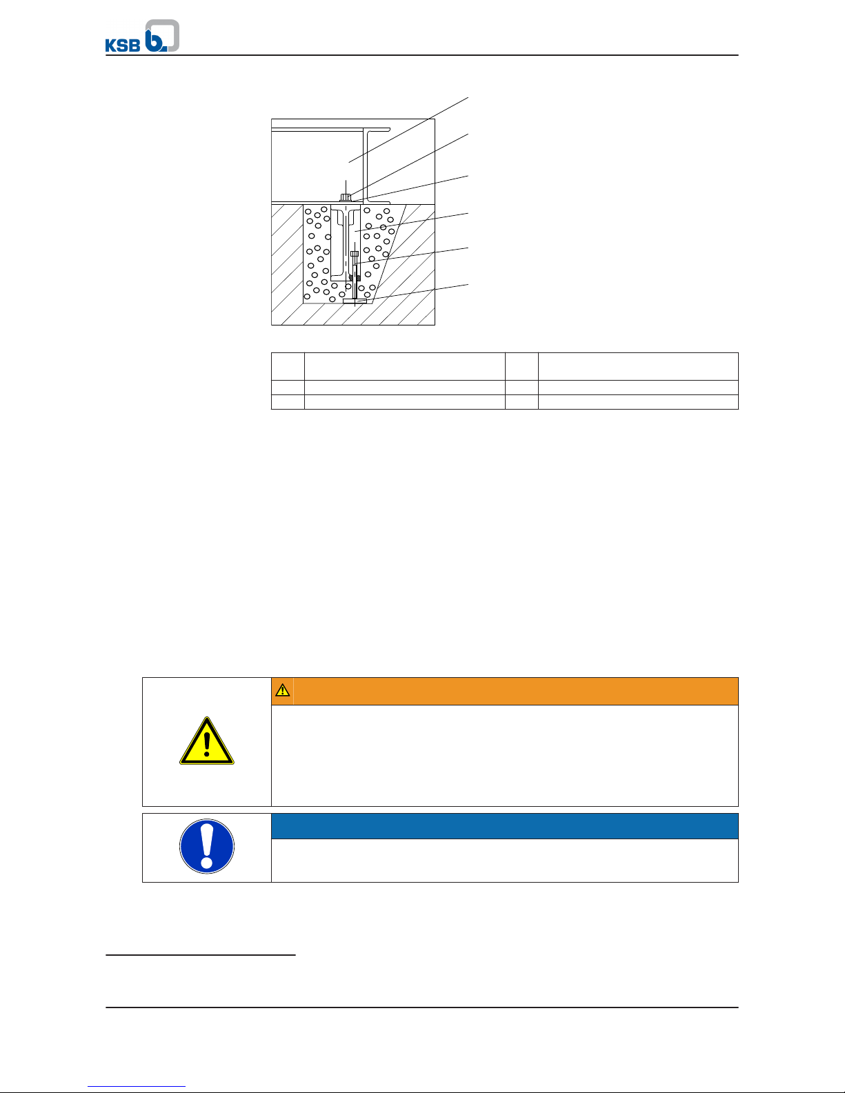
Fig. 7: Installation drawing
1
Foot, part No. 182 2 Hexagon head bolt, part No.
901-11
3 Disc, part No. 550.05 4 Foundation block, part No. 898.01
5 Adjusting screw, part No. 901.10 6 Shim, part No. 89-4.04
1. Screw the foundation blocks (4) with hexagon head bolts (2) and discs (3) to the
foot (1).
2. Screw the adjusting screws (5) into the foundation blocks (4).
3. Place the shim (6) into the recesses for the foundation blocks (4) in accordance
with the general arrangement drawing.
4. Align the pump with the piping.
5. Place the foot (4) including the foundation blocks (1) with the adjusting screws
(5) on the shims (6). Use the adjusting screws to align the foot.
6. Grout the holes for the foundation blocks with a quick-setting, low-shrinkage
concrete mixture.
6)
7. When the concrete has set, tighten the foundation bolts (2) evenly.
8. Connect the piping to the pump without transmitting any stresses or strains.
(⇨ Section 5.4 Page 30)
5.3.3
Installation type DJ with cardan shaft
WARNING
Exposed rotating coupling or universal-joint shaft
Risk of injury by rotating shafts!
▷ Always operate the pump set with a coupling guard.
If the customer specifically requests not to include a coupling guard in KSB's
delivery, then the operator must supply one!
▷ Observe all relevant regulations for selecting a coupling guard.
NOTE
If the customer specifically requests not to include a cardan shaft guard in our
delivery, then the operator must supply one.
For installing and aligning the cardan shaft refer to the technical product literature
of the cardan shaft manufacturer.
6)
Minimum strength class C25/30
5 Installation at Site
26 of 94
Omega / Omega V
Page 27

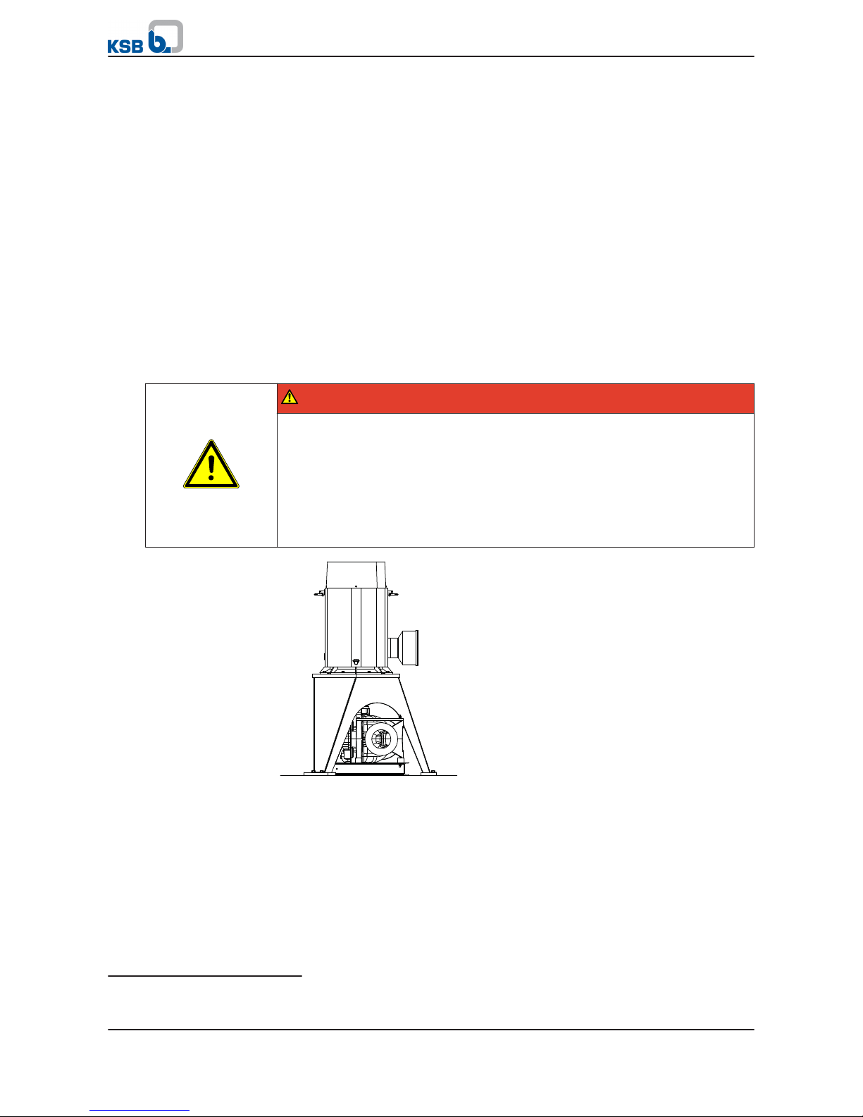
5.3.4 Type of installation DB and DK
DANGER
The pump or individual components could slip out of the suspension arrangement
Danger to life from falling parts!
▷ Always transport the pump or components in the specified position.
▷ Never attach the suspension arrangement to the free shaft end of the pump.
▷ Refer to the weights indicated for the individual components.
▷ Observe the applicable local health and safety regulations.
▷ Use suitable, permitted lifting accessories.
Fig. 8: DB and DK installation
✓ The relevant general arrangement drawing is available.
✓ The foundation has the required strength and characteristics.
✓ The foundation has been prepared in accordance with the dimensions given in
the general arrangement drawing.
1
2
3
4
5
6
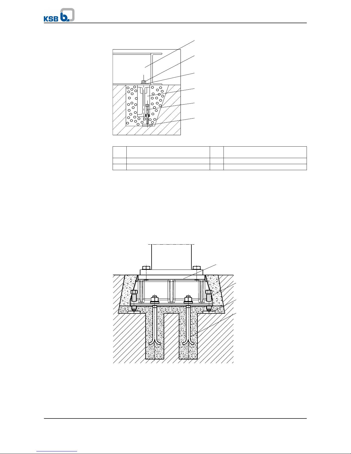
Fig. 9: Installation drawing
1
Foot, part No. 182 2 Hexagon head bolt, part No.
901-11
3 Disc, part No. 550.05 4 Foundation block, part No. 898.01
5 Adjusting screw, part No. 901.10 6 Shim, part No. 89-4.04
1. Screw the foundation blocks (4) with hexagon head bolts (2) and discs (3) to the
foot (1).
2. Screw the adjusting screws (5) into the foundation blocks (4).
5 Installation at Site
Omega / Omega V
27 of 94
Page 28
3. Place the shim (6) into the recesses for the foundation blocks (4) in accordance
with the general arrangement drawing.
4. Align the pump with the piping.
5. Place the foot (4) including the foundation blocks (1) with the adjusting screws
(5) on the shims (6). Use the adjusting screws to align the foot so that the
machined motor flange of the drive lantern is horizontal in both dimensions.
6. Grout the holes for the foundation blocks with a quick-setting, low-shrinkage
concrete mixture.
7)
7. When the concrete has set, tighten the foundation bolts (2) evenly.
8. Connect the piping to the pump without transmitting any stresses or strains.
(⇨ Section 5.4 Page 30)
9. Mount the motor on the drive lantern as described in the motor manufacturer's
operating instructions.
10. Align the coupling as described in the coupling manufacturer's operating
instructions.
5.3.5
Type of installation DP
DANGER
The pump or individual components could slip out of the suspension arrangement
Danger to life from falling parts!
▷ Always transport the pump or components in the specified position.
▷ Never attach the suspension arrangement to the free shaft end of the pump.
▷ Refer to the weights indicated for the individual components.
▷ Observe the applicable local health and safety regulations.
▷ Use suitable, permitted lifting accessories.
Fig. 10: Pump on foot (baseplate), drive on support frame
✓ The relevant general arrangement drawing is available.
✓ The foundation has the required strength and characteristics.
✓ The foundation has been prepared in accordance with the dimensions given in
the outline drawing.
7)
Minimum strength class C25/30
5 Installation at Site
28 of 94
Omega / Omega V
Page 29
1
2
3
4
5
6
Fig. 11: Installation drawing
1
Foot, part No. 182 2 Hexagon head bolt, part No.
901-11
3 Disc, part No. 550.05 4 Foundation block, part No. 898.01
5 Adjusting screw, part No. 901.10 6 Shim, part No. 89-4.04
1. Screw the foundation blocks (4) with hexagon head bolts (2) and discs (3) to the
foot (1).
2. Screw the adjusting screws (5) into the foundation blocks (4).
3. Place the shim (6) into the recesses for the foundation blocks (4) in accordance
with the general arrangement drawing.
4. Align the pump with the piping.
5. Place the foot (4) including the foundation blocks (1) with the adjusting screws
(5) on the shims (6). Use the adjusting screws to align the foot.
Installing the motor support frame
1
2
3
4
Fig. 12: Installation drawing
1. Screw adjusting screws (2) into the foundation rails (1) in accordance with the
general arrangement drawing.
2. Insert the foundation bolts (4) into the drilled holes of the foundation rails (1).
3. Place shims (3) into the recesses for the foundation rails (1) in the foundation.
5 Installation at Site
Omega / Omega V
29 of 94
Page 30

4. Use suitable lifting equipment to place the motor support frame on the
foundation together with the pre-assembled foundation rails (1), the adjusting
screws (2) and the inserted foundation bolts (4). Vertically position the adjusting
screws (2) on the shims (3).
DANGER
Unsecured motor
Danger from falling components!
▷ Always secure the motor additionally with a crane until the support frame has
been completely grouted and the concrete has reached its full strength.
5. Align the motor support frame with the pump. For the alignment, the motor
can be fastened to the support frame (see the manufacturer's product literature
included with the supplied documentation).
6. Grout the holes for the foundation bolts with quick-setting, low-shrinkage
concrete8). Make sure that the space underneath the foundation rails is
completely grouted.
7. When the concrete has set, tighten the foundation bolts.
8. Grout the recesses in the foundation for the foundation rails with a quicksetting, low-shrinkage concrete mixture8).
9. When the concrete has set, the motor can be fastened to the support frame.
Observe the motor manufacturer's operating instructions.
Final assembly
1. Align the pump on the foot (base plate) with the motor on the support frame.
Align and connect the pump with the piping. (⇨ Section 5.4 Page 30)
2. Grout the recesses for the foundation blocks with a quick-setting, low-shrinkage
concrete mixture8).
3. When the concrete has set, tighten the foundation bolts (2) evenly.
4. Connect the piping to the pump without transmitting any stresses or strains.
(⇨ Section 5.4 Page 30)
5. Fasten the motor to the support frame in accordance with the general
arrangement drawing.
6. Install and align the coupling in accordance with the coupling manufacturer's
operating instructions (see the manufacturer's product literature included with
the supplied documentation).
5.4
Connecting the piping
DANGER
Impermissible loads acting on the pump nozzles
Danger to life from leakage of hot, toxic, corrosive or flammable fluids!
▷ Do not use the pump as an anchorage point for the piping.
▷ Anchor the pipes in close proximity to the pump and connect them without
transmitting any stresses or strains.
▷ Observe the permissible forces and moments at the pump nozzles.
▷ Take appropriate measures to compensate for thermal expansion of the piping.
8)
Refer to the general arrangement drawing for the required concrete quality.
5 Installation at Site
30 of 94
Omega / Omega V
Page 31

CAUTION
Incorrect earthing during welding work at the piping
Destruction of rolling element bearings (pitting effect)!
▷ Never earth the electric welding equipment on the pump or baseplate.
▷ Prevent current flowing through the rolling element bearings.
NOTE
Installing check and shut-off elements in the system is recommended, depending on
the type of plant and pump. However, such elements must not obstruct proper
drainage or hinder disassembly of the pump.
✓ Suction lift lines have been laid with a rising slope, suction head lines with a
downward slope towards the pump.
✓ A flow stabilisation section having a length equivalent to at least five times the
diameter of the suction flange has been provided upstream of the suction
flange.
✓ The nominal diameters of the pipes are equal to or greater than the nominal
diameters of the pump nozzles.
✓ To prevent excessive pressure losses, adapters to larger diameters have a
diffuser angle of approx. 8°.
✓ The pipelines have been anchored in close proximity to the pump and
connected without transmitting any stresses or strains.
1. Thoroughly clean, flush and blow through all vessels, pipelines and connections
(especially of new installations).
2. Before installing the pump in the piping, remove any flange covers on the
suction and discharge nozzles of the pump.
Fig. 13: Connection with expansion joints
CAUTION
Pumps connected with unbraced expansion joints
Machine damage by impermissible nozzle loads!
▷ Never connect the pump with unbraced expansion joints.
3. If the owner/operator supplies an expansion joint, it has to be braced with
external tie rods to prevent impermissible nozzle loads.
5 Installation at Site
Omega / Omega V
31 of 94
Page 32

CAUTION
Welding beads, scale and other impurities in the piping
Damage to the pump!
▷ Free the piping from any impurities.
▷ If necessary, install a filter.
▷ Comply with the instructions set out in (⇨ Section 7.2.2.4 Page 52) .
4. If required, install a filter in the piping.
5. Connect the pump nozzles to the piping.
CAUTION
Aggressive flushing and pickling agents
Damage to the pump!
▷ Match the cleaning operation mode and duration for flushing and pickling
service to the casing and seal materials used.
5.5 Enclosure/insulation
WARNING
Failure to re-install or re-activate protective devices
Risk of injury from moving parts or escaping fluid!
▷ As soon as the work is completed, re-install and/or re-activate any safety-
relevant and protective devices.
CAUTION
Heat build-up in the bearing housing
Damage to the bearing!
▷ Never insulate the bearing housing and bearing cover.
5.6 Aligning the pump and motor
DANGER
Inadmissible temperatures at the coupling or bearings due to misalignment of the
coupling
Explosion hazard!
Risk of burns!
▷ Make sure that the coupling is correctly aligned at all times.
CAUTION
Misalignment of pump and motor shafts
Damage to pump, motor and coupling!
▷ Always check the coupling after the pump has been installed and connected to
the piping.
▷ Also check the coupling of pump sets supplied with pump and motor mounted
on the same baseplate.
5 Installation at Site
32 of 94
Omega / Omega V
Page 33

5.6.1 Aligning the motor with adjusting screws
1
3
2
Fig. 14:
Aligning the motor with adjusting screws
1
Hexagon head bolt 2 Adjusting screw
3 Locknut
✓ The coupling guard and the footboard for the coupling guard, if any, have
been removed.
1. Place the straight-edge (c) axially on both coupling halves.
2. Leave the straight-edge (c) in this position and turn the coupling by hand.
⇨ The coupling is correctly aligned if the distances A and B to the respective
shafts are the same at all points around the circumference. The radial and
axial deviation of the two coupling halves must not exceed 0.05 mm. Observe
the coupling manufacturer's operating instructions!
3. Unscrew the hexagon head bolts (1) at the motor and the locknuts (3) at the
baseplate.
4. Turn the adjusting screws (2) by hand or by means of an open-end wrench until
the coupling alignment is correct and all motor feet rest squarely on the
baseplate.
5. Re-tighten the hexagon head bolts (1) at the motor and the locknuts (3) at the
baseplate.
6. Check that coupling/shaft can easily be rotated by hand.
WARNING
Unprotected rotating coupling
Risk of injury by rotating shafts!
▷ Always operate the pump set with a coupling guard.
If the customer specifically requests not to include a coupling guard in KSB's
delivery, then the operator must supply one!
▷ Observe all relevant regulations for selecting a coupling guard.
DANGER
Risk of ignition by frictional sparks
Explosion hazard!
▷ Choose a coupling guard material that is non-sparking in the event of
mechanical contact (see DIN EN 13463-1).
7. Re-install the coupling guard and the footboard for the coupling guard, if any.
8. Check the distance between coupling and coupling guard.
The coupling guard must not touch the coupling.
B
A
A
B
c
c d
Fig. 15: Checking the
coupling alignment
5 Installation at Site
Omega / Omega V
33 of 94
Page 34

5.6.2 Aligning the motor without adjusting screws
1
Fig. 16:
Aligning the motor without adjusting screw
1
Shim
✓ The coupling guard and the footboard for the coupling guard, if any, have
been removed.
1. Place the straight-edge (c) axially on both coupling halves.
2. Leave the straight-edge (c) in this position and turn the coupling by hand.
⇨ The coupling is correctly aligned if the distances A and B to the respective
shafts are the same at all points around the circumference. The radial and
axial deviation of the two coupling halves must not exceed 0.05 mm. Observe
the coupling manufacturer's operating instructions!
3. In case of a misalignment loosen the hexagon head bolts at the motor.
4. Insert shims (1) underneath the motor feet until the difference in shaft
centreline height has been compensated.
5. Re-tighten the hexagon head bolts.
6. Check that coupling/shaft can easily be rotated by hand.
WARNING
Unprotected rotating coupling
Risk of injury by rotating shafts!
▷ Always operate the pump set with a coupling guard.
If the customer specifically requests not to include a coupling guard in KSB's
delivery, then the operator must supply one!
▷ Observe all relevant regulations for selecting a coupling guard.
DANGER
Risk of ignition by frictional sparks
Explosion hazard!
▷ Choose a coupling guard material that is non-sparking in the event of
mechanical contact (see DIN EN 13463-1).
7. Re-install the coupling guard and the footboard for the coupling guard, if any.
8. Check the distance between coupling and coupling guard.
The coupling guard must not touch the coupling.
5.7 Permissible forces and moments at the pump nozzles
The resulting permissible forces have been determined according to
B
A
A
B
c
c d
Fig. 17: Checking the
coupling alignment
5 Installation at Site
34 of 94
Omega / Omega V
Page 35

The forces and moments indicated refer to external, simultaneous loads in 3
dimensions (Fx = Fy = Fz and Mx = My = Mz). They only apply if the pump set has been
properly installed in accordance with the installation/operating manual. The forces
and moments in any direction must not exceed the values given in the table. The
data on forces and moments apply to static piping loads only. If the limits are
exceeded, the values must be checked and verified. The piping must be connected
without transmitting any stresses or strains. The pump must not be used as support
for the piping. The pump is not an anchorage point for the piping. The piping must
be fastened without transmitting any forces, vibrations or pipe weights to the pump.
Observe the limits for forces and moments at the suction and discharge nozzle. The
pump must not be connected with unbraced expansion joints.
F
x
F
z
F
y
M
y
M
z
M
x
Fig. 18: Flange coordinates
Table 10: Forces and moments at the pump nozzles depending on the material [N/Nm]
Size Grey cast iron (GB/GC) Nodular cast iron (SB/SC) Cast steel (DD35)
Fx / Fy / Fz Mx / My / Mz Fx / Fy / Fz Mx / My / Mz Fx / Fy / Fz Mx / My / Mz
[N] [Nm] [N] [Nm] [N] [Nm]
80 - 210 800 500 1120 700 1520 950
80 - 270 800 500 1120 700 1520 950
80 - 370 800 500 1120 700 1520 950
100 - 250 1000 700 1400 980 1900 1330
100 - 310 1000 700 1400 980 1900 1330
100 - 375 1000 700 1400 980 1900 1330
125 - 230 1500 1000 2100 1400 2850 1900
125 - 290 1500 1000 2100 1400 2850 1900
125 - 365 2000 1500 2800 2100 3800 2850
125 - 500 2000 1500 2800 2100 3800 2850
150 - 290 2500 1500 3500 2100 4750 2850
150 - 360 2500 2000 3500 2800 4750 3800
150 - 460 2500 2000 3500 2800 4750 3800
150 - 605 3000 2000 4200 2800 5700 3800
200 - 320 4000 2750 5600 3850 7600 5225
200 - 420 4000 2750 5600 3850 7600 5225
200 - 520 4000 2750 5600 3850 7600 5225
200 - 670 4000 2750 5600 3850 7600 5225
250 - 370 4000 2750 5600 3850 7600 5225
250 - 480 4000 2750 5600 3850 7600 5225
250 - 600 4000 2750 5600 3850 7600 5225
250 - 800 4000 2750 5600 3850 7600 5225
300 - 300 4000 3000 5600 4200 7600 5700
300 - 435 4000 3000 5600 4200 7600 5700
5 Installation at Site
Omega / Omega V
35 of 94
Page 36

Size Grey cast iron (GB/GC) Nodular cast iron (SB/SC) Cast steel (DD35)
Fx / Fy / Fz Mx / My / Mz Fx / Fy / Fz Mx / My / Mz Fx / Fy / Fz Mx / My / Mz
[N] [Nm] [N] [Nm] [N] [Nm]
300 - 560 5000 3000 7000 4200 9500 5700
300 - 700 5000 3000 7000 4200 9500 5700
300 - 860 5000 3000 7000 4200 9500 5700
350 - 360 5000 3000 7000 4200 9500 5700
350 - 430 5000 3000 7000 4200 9500 5700
350 - 510 5000 3000 7000 4200 9500 5700
5.8 Auxiliary connections
WARNING
Screw plugs subjected to pressure
Risk of injuries by parts flying off and escaping fluid!
▷ Never use screw plugs for releasing pressure from the pump casing.
▷ Always use suitable venting devices (e.g. vent valve).
WARNING
Failure to use or incorrect use of auxiliary connections (e.g. barrier fluid, flushing
liquid, etc.)
Risk of injury from escaping fluid!
Risk of burns!
Malfunction of the pump!
▷ Refer to the general arrangement drawing, the piping layout and pump
markings (if any) for the quantity, dimensions and locations of auxiliary
connections.
▷ Use the auxiliary connections provided.
WARNING
Open pipelines
Risk of injuries by escaping fluid!
Risk of burns!
▷ Always close the shut-off valve (e.g. ball valve), if any, with the safety device
engaged to prevent it from being opened unintentionally.
▷ Guide open pipelines away from the system in such a way that hazards by
escaping fluid are prevented.
The pump is supplied with a flushing line fitted at the factory.
The following auxiliary connections are available:
5 Installation at Site
36 of 94
Omega / Omega V
Page 37

6B
6D
1M.1 1M.2
1M.1
1M.2
6D
6B.2
8A
26M.1
4M.2
4M.1
26M.2
4M.1
26M.1
6B.1
8A
Fig. 19: Auxiliary connections
Table 11: Auxiliary connections
Connection
Description Type of
connection
1M.1 Connection for pressure measurement on
the suction side
G 1/2
1M.2 Connection for pressure measurement on
the discharge side
G 1/2
4M.1 Connection for temperature measurement
at the drive end
G 3/8
4M.2 Connection for temperature measurement
at the non-drive end
G 3/8
6B Connection for pump drain on the suction side G 1/2
6B.1
9)
Connection for pump drain on the suction side G 1/2
6B.2 Connection for pump drain on the discharge side G 1/2
6D Connection for venting the pump G 1/2
8A Connection for leakage drain G 3/4
26M.1 Connection for vibration measurement
at the drive end
M8
26M.2 Connection for vibration measurement
at the non-drive end
M8
5.9 Connection to power supply
DANGER
Incorrect electrical installation
Explosion hazard!
▷ For electrical installation, also observe the requirements of IEC 60079-14.
▷ Always use a motor protection switch for explosion-proof motors.
DANGER
Electrical connection work by unqualified personnel
Danger of death from electric shock!
▷ Always have the electrical connections installed by a trained and qualified
electrician.
▷ Observe regulations IEC 60364 and, for explosion-proof models, EN 60079.
▷ Observe the motor manufacturer's operating instructions.
9)
Applies to sizes 100 - 375, 150 - 290, 150 - 360, 150 - 605, 200 - 420, 200 - 520, 200 - 670, 250 - 600, 250 - 800, 300 - 300, 300
- 435, 300 - 560, 300 - 700, 300 - 860, 350 - 360, 350 - 430, 350 - 510
5 Installation at Site
Omega / Omega V
37 of 94
Page 38

WARNING
Unintentional starting of pump set
Risk of injury by moving parts!
▷ Ensure that the pump set cannot be started up unintentionally.
▷ Always make sure the electrical connections are disconnected before carrying
out work on the pump set.
WARNING
Incorrect connection to the mains
Damage to the mains network, short circuit!
▷ Observe the technical specifications of the local energy supply companies.
1. Check the available mains voltage against the data on the motor name plate.
2. Select an appropriate start-up method.
NOTE
A motor protection device is recommended.
5.9.1 Earthing
DANGER
Electrostatic charging
Explosion hazard!
Fire hazard!
Damage to the pump set!
▷ Connect the PE conductor to the earthing terminal provided.
5.10 Checking the direction of rotation
DANGER
Temperature increase resulting from contact between rotating and stationary
components
Explosion hazard!
Damage to the pump set!
▷ Never check the direction of rotation by starting up the unfilled pump set.
▷ Separate the pump from the motor to check the direction of rotation.
DANGER
Rotating shaft during direction of rotation check
Risk of injury!
▷ Maintain a safe distance to the pump set.
▷ Comply with the general health and safety regulations.
CAUTION
Drive and pump running in the wrong direction of rotation
Damage to the pump!
▷ Refer to the arrow indicating the direction of rotation on the pump.
▷ Check the direction of rotation. If required, check the electrical connection and
correct the direction of rotation.
5 Installation at Site
38 of 94
Omega / Omega V
Page 39

✓ The pump has been completely separated from the motor.
✓ All components at the motor (e.g. coupling half at the motor shaft) have been
secured.
1. Start the motor and stop it again immediately to determine the motor's
direction of rotation.
2. Check the direction of rotation.
The motor's direction of rotation must match the arrow indicating the direction
of rotation on the pump.
3. If the motor runs in the wrong direction of rotation, check the electrical
connection of the motor and the control system, if applicable.
5.11 Removing the transport lock
This type of transport lock is only used for vertical pumps with a product-lubricated
plain bearing.
160
901.17
Fig. 20:
Transport lock
1. Undo bolt 901.17 at cover 160.
2. Connect a flushing line to the drilled hole in cover 160.
5 Installation at Site
Omega / Omega V
39 of 94
Page 40

6 Commissioning/Start-up/Shutdown
6.1 Commissioning/start-up
6.1.1 Prerequisites for commissioning/start-up
Before starting up the pump set make sure that the following requirements are met:
▪ The pump set has been properly connected to the electric power supply and is
equipped with all protection devices. (⇨ Section 5.9 Page 37)
▪ The pump has been primed with the fluid to be handled. (⇨ Section 6.1.2 Page
40)
▪ The direction of rotation has been checked. (⇨ Section 5.10 Page 38)
▪ All auxiliary connections required are connected and operational.
▪ The transport lock has been removed.
▪ The lubricants have been checked and filled in.
▪ After prolonged shutdown of the pump (set), the activities described in
(⇨ Section 6.4 Page 46) have been carried out.
▪ The coupling alignment has been checked.
6.1.2
Priming and venting the pump
DANGER
Risk of potentially explosive atmosphere inside the pump
Explosion hazard!
▷ Before starting up the pump, vent the suction line and the pump and prime
them with the fluid to be handled.
DANGER
Shaft seal failure caused by insufficient lubrication
Hot fluid may escape!
▷ Before starting up the pump set, vent the pump and suction line and prime
both with the fluid to be handled.
1. Close all drains and drain lines.
2. Vent the pump and suction line and prime both with the fluid to be handled.
In case of suction lift operation, evacuate the pump.
3. Fully open the shut-off element in the suction line.
4. If the discharge line is equipped with a check valve, the shut-off element in the
discharge line may remain open as long as there is some back pressure. If this is
not the case, the shut-off element in the discharge line must be closed.
5. Fully open all auxiliary connections (barrier fluid, flushing liquid, etc).
6 Commissioning/Start-up/Shutdown
40 of 94
Omega / Omega V
Page 41

6.1.3 Start-up
DANGER
Non-compliance with the permissible pressure and temperature limits if the pump is
operated with the suction and/or discharge line closed.
Explosion hazard!
Leakage of hot or toxic fluids!
▷ Never operate the pump with the shut-off elements in the suction line and/or
discharge line closed.
▷ Only start up the pump set with the discharge-side shut-off element slightly or
fully open.
DANGER
Excessive temperatures due to dry running or excessive gas content in the fluid
handled
Explosion hazard!
Damage to the pump set!
▷ Never operate the pump set without liquid fill.
▷ Prime the pump as per operating instructions.
▷ Always operate the pump within the permissible operating range.
WARNING
Pump sets with high noise levels
Damage to hearing!
▷ Persons must only enter the vicinity of the running pump set if they are wearing
protective equipment/ear protection.
▷ See noise characteristics. (⇨ Section 4.6 Page 20)
CAUTION
Abnormal noises, vibrations, temperatures or leakage
Damage to the pump!
▷ Switch off the pump (set) immediately.
▷ Eliminate the causes before returning the pump set to service.
✓ The system piping has been cleaned.
✓ Pump, suction line and inlet tank, if any, have been vented and primed with the
fluid to be pumped.
✓ The lines for priming and venting have been closed.
CAUTION
Start-up against open discharge line
Motor overload!
▷ Make sure the motor has sufficient power reserves.
▷ Use a soft starter.
▷ Use speed control.
1. Fully open the shut-off element in the suction head/suction lift line.
2. Close or slightly open the shut-off element in the discharge line.
3. Start up the motor.
4. Immediately after the pump has reached full rotational speed, slowly open the
shut-off element in the discharge line and adjust it to comply with the duty
point.
6 Commissioning/Start-up/Shutdown
Omega / Omega V
41 of 94
Page 42

6.1.4 Checking the shaft seal
The mechanical seal only leaks slightly or invisibly (as vapour) during operation.
Mechanical seals are maintenance-free.
The gland packing must drip slightly during operation.
DANGER
The temperatures at the gland packing have risen above the permissible limits
Explosion hazard!
▷ Gland packings are not approved for use in potentially explosive atmospheres.
▷ Immediately switch off the pump set!
The minimum leakage required depends on the fluid handled, pressure, slip velocity
and temperature.
Table 12: Leakage rates at the gland packing
Limits Leakage
Minimum 10 drops/min. (approx. 0.5 ml)
Maximum 120 drops/min. (approx. 6 ml)
CAUTION
Excessive leakage or no leakage at the gland packing
Damage to the pump!
▷ Excessive leakage: Re-tighten the gland follower until the required leakage rate
is reached.
▷ No leakage: Switch off the pump set immediately.
Adjusting the leakage
1. Only lightly tighten the nuts of the gland follower by hand.
2. Use a feeler gauge to verify that the gland follower is mounted centred and at
a right angle to the shaft.
⇨ The gland must leak after the pump has been primed.
WARNING
Unprotected rotating parts
Risk of personal injury!
▷ Do not touch rotating parts.
▷ When the pump is running, perform any work with utmost caution.
The leakage can be reduced.
1. Tighten the nuts on the gland follower by 1/6 turn.
2. Monitor the leakage for another five minutes.
Excessive leakage:
Repeat steps 1 and 2 until the minimum value has been reached.
Not enough leakage:
Slightly loosen the nuts at the gland follower.
No leakage:
Immediately switch off pump set!
Loosen the gland follower and repeat commissioning.
Checking the leakage
After the leakage has been adjusted, monitor the leakage for about two hours at
maximum fluid temperature.
Check that enough leakage occurs at the gland packing at minimum fluid pressure.
Mechanical seal
Gland packing
Prior to commissioning
After five minutes of
operation
6 Commissioning/Start-up/Shutdown
42 of 94
Omega / Omega V
Page 43

6.1.5 Shutdown
CAUTION
Backflow of the fluid handled
Motor or winding damage!
Excessive reverse runaway speed of the motor!
▷ Observe the permissible reverse runaway speed of the motor. See the
manufacturer's product literature included with the supplied documentation.
▷ Close the shut-off elements.
✓ The shut-off element in the suction line is and remains open.
1. Close the shut-off element in the discharge line.
2. Switch off the motor and make sure the pump set runs down smoothly to a
standstill.
NOTE
If the discharge line is equipped with a check valve, the shut-off element in the
discharge line may remain open, provided the site's requirements and regulations
are taken into account and observed.
For prolonged shutdown periods:
1. Close the shut-off element in the suction line.
2. Close the auxiliary connections.
CAUTION
Risk of freezing during prolonged pump shutdown periods
Damage to the pump!
▷ Drain the pump and the cooling/heating chambers (if any) or otherwise protect
them against freezing.
6.2 Operating limits
DANGER
Non-compliance with operating limits for pressure, temperature, fluid handled and
speed
Explosion hazard!
Hot or toxic fluid could escape!
▷ Comply with the operating data indicated in the data sheet.
▷ Never use the pump for handling fluids it is not designed for.
▷ Avoid prolonged operation against a closed shut-off element.
▷ Never operate the pump at temperatures, pressures or rotational speeds
exceeding those specified in the data sheet or on the name plate unless the
written consent of the manufacturer has been obtained.
6.2.1 Maximum operating pressure
CAUTION
Permissible operating pressure exceeded
Damage to connections and seals!
▷ Never exceed the operating pressure specified in the data sheet.
6 Commissioning/Start-up/Shutdown
Omega / Omega V
43 of 94
Page 44

The maximum operating pressure depends on the pump size, pump material and
nominal pressure of the flange design.
Neither the material/size-dependent maximum pressure indicated in the data sheet
nor the maximum nominal flange pressure must be exceeded.
6.2.2 Hydraulic operating range
CAUTION
Non-compliance with hydraulic operating limits
Damage to the pump and motor
▷ Observe the limits in the data sheet.
▷ Brief passage through the critical range below Q
min
is permissible during start-
up.
General information on the hydraulic operating range
NPSH
Required
NPSH
Available
Q
min
Q
H
Q
max
Q-H
curve
B
A
A
C
System curve
Fig. 21:
Pump operating range
NPSH
Available
Inlet pressure available in
the system
NPSH
Required
Required inlet pressure
A Operating limit B Operating point
C Operating range without
NPSH margin
The flow rate Q will develop automatically as a function of the discharge head H, in
line with the pump's characteristic curve. The pump's permissible operating range has
limits that are independent of each other in terms of their cause.
Low flow operating limit
This limit is indicated in the H/Q characteristic by Q
min
or by discontinuation of the
characteristic curve in the diagram.
NPSH-related limits under off-design conditions
The low flow and overload limits are determined by the ratio of NPSH
Required
to
NPSH
Available
.
The NPSH limits are determined as follows:
The intersections of NPSH
Required
and NPSH
Available
are projected onto the H/Q
characteristic, where they represent the operating limits.
If the pump set is operated outside its operating limits or system-related changes
occur, check the NPSH values.
If necessary, consult your nearest customer service centre.
6 Commissioning/Start-up/Shutdown
44 of 94
Omega / Omega V
Page 45

6.2.3 Frequency of starts
DANGER
Excessive surface temperature of the motor
Explosion hazard!
Damage to the motor!
▷ In case of explosion-proof motors, observe the frequency of starts specified in
the manufacturer's product literature.
CAUTION
Re-starting while motor is still running down
Damage to the pump (set)!
▷ Do not re-start the pump set before the pump rotor has come to a standstill.
The frequency of starts is usually determined by the maximum temperature increase
of the motor. This largely depends on the power reserves of the motor in steadystate operation and on the starting conditions (DOL, star-delta, moments of inertia,
etc).
Observe the motor manufacturer's operating instructions.
6.2.4 Fluid handled
6.2.4.1 Temperature of the fluid handled
CAUTION
Fluid temperature too high or too low
Damage to the pump!
▷ Never operate the pump set against a closed shut-off element.
▷ Never operate the pump at temperatures above or below those specified in the
data sheet or on the name plate unless the written consent of the manufacturer
has been obtained.
If the values are not indicated in the data sheet, the following temperature limits
apply. The temperatures must neither be below nor above these limits.
Table 13: Temperature limits of the fluid handled
Minimum fluid temperature 0 °C
Maximum fluid temperature + 80 °C
6.2.4.2 Abrasive fluids/solids
CAUTION
Abrasive particles or solids in the fluid
Damage to the pump!
▷ Comply with the limits indicated in the data sheet.
▷ Flush the piping prior to commissioning.
▷ Install a filter in the system, if required.
Do not exceed the maximum permissible solids content specified in the data sheet.
When the pump handles fluids containing abrasive substances, increased wear of the
hydraulic system and shaft seal are to be expected. In this case, reduce the commonly
recommended inspection intervals.
6 Commissioning/Start-up/Shutdown
Omega / Omega V
45 of 94
Page 46

NOTE
Solids, especially long fibres, plastic residues or similar, can lead to clogging of the
barrier or flushing lines and to mechanical seal damage.
6.3 Shutdown/storage/preservation
CAUTION
Corrosion caused by stagnant aggressive fluids, e.g. fluids containing chloride
Damage to the pump!
▷ Every 24 hours operate the pump for a minimum of 30 minutes or flush it with
clean, pure water.
10)
The pump (set) remains installed
✓ Sufficient fluid is supplied for the operation check run of the pump.
1. Start up the pump (set) regularly between once a month and once every three
months for approximately five minutes during prolonged shutdown periods.
This will prevent the formation of deposits within the pump and the pump
intake area.
The pump (set) is removed from the pipe and stored
✓ The pump has been properly drained (⇨ Section 7.3 Page 53) and the safety
instructions for dismantling the pump have been observed.
1. Spray-coat the inside wall of the pump casing, and in particular the impeller
clearance areas, with a preservative.
2. Spray the preservative through the suction and discharge nozzles.
It is advisable to close the pump nozzles (e.g. with plastic caps or similar).
3. Oil or grease all exposed machined parts and surfaces of the pump (with
silicone-free oil and grease, food-approved if required) to protect them against
corrosion.
Observe the additional instructions (⇨ Section 3.3 Page 14) .
6.4 Returning to service
For returning the pump to service observe the sections on commissioning/start-up
and the operating limits.
In addition, carry out all servicing/maintenance operations before returning the
pump (set) to service.
WARNING
Failure to re-install or re-activate protective devices
Risk of personal injury from moving parts or escaping fluid!
▷ As soon as the work is complete, re-install and/or re-activate any safety-relevant
and protective devices.
NOTE
On pumps/pump sets older than 5 years we recommend replacing all elastomer
seals.
10)
E.g. drinking water or demineralised water
6 Commissioning/Start-up/Shutdown
46 of 94
Omega / Omega V
Page 47

7 Servicing/Maintenance
7.1 Safety regulations
DANGER
Sparks produced during servicing work
Explosion hazard!
▷ Observe the safety regulations in force at the place of installation!
▷ Always perform maintenance work on explosion-proof pump sets outside
potentially explosive atmospheres.
DANGER
Improperly serviced pump set
Explosion hazard!
Damage to the pump set!
▷ Service the pump set regularly.
▷ Prepare a maintenance schedule with special emphasis on lubricants, shaft seal
and coupling.
DANGER
Excessive temperatures due to dry running
Explosion hazard!
Fire hazard!
Damage to the pump set!
▷ Never operate the pump set without liquid fill.
▷ Never close the shut-off element in the suction line and/or supply line during
pump operation.
DANGER
Excessive temperatures as a result of bearings running hot or defective bearing seals
Explosion hazard!
Fire hazard!
Damage to the pump set!
▷ Regularly check the rolling element bearings for running noises.
The operator ensures that maintenance, inspection and installation is performed by
authorised, qualified specialist personnel who are thoroughly familiar with the
manual.
WARNING
Unintentional starting of pump set
Risk of injury by moving parts!
▷ Ensure that the pump set cannot be started up unintentionally.
▷ Always make sure the electrical connections are disconnected before carrying
out work on the pump set.
7 Servicing/Maintenance
Omega / Omega V
47 of 94
Page 48

WARNING
Fluids, consumables and supplies which are hot and/or pose a health hazard
Risk of injury!
▷ Observe all relevant laws.
▷ When draining the fluid take appropriate measures to protect persons and the
environment.
▷ Decontaminate pumps which handle fluids posing a health hazard.
WARNING
Insufficient stability
Risk of crushing hands and feet!
▷ During assembly/dismantling, secure the pump (set)/pump parts to prevent
tipping or falling over.
A regular maintenance schedule will help avoid expensive repairs and contribute to
trouble-free, reliable operation of the pump, pump set and pump parts with a
minimum of servicing/maintenance expenditure and work.
NOTE
All maintenance, service and installation work can be carried out by KSB Service or
authorised workshops. For contact details please refer to the enclosed "Addresses"
booklet or visit "www.ksb.com/contact" on the Internet.
Never use force when dismantling and reassembling the pump set.
7.2 Servicing/inspection
7.2.1 Supervision of operation
DANGER
Risk of potentially explosive atmosphere inside the pump
Explosion hazard!
▷ The pump internals in contact with the fluid to be handled, including the seal
chamber and auxiliary systems must be filled with the fluid to be handled at all
times.
▷ Provide sufficient inlet pressure.
▷ Provide an appropriate monitoring system.
DANGER
Excessive temperatures as a result of bearings running hot or defective bearing seals
Explosion hazard!
Fire hazard!
Damage to the pump set!
Risk of burns!
▷ Regularly check the lubricant level.
▷ Regularly check the rolling element bearings for running noises.
7 Servicing/Maintenance
48 of 94
Omega / Omega V
Page 49

DANGER
Excessive temperatures due to dry running
Explosion hazard!
Fire hazard!
Damage to the pump set!
▷ Never operate the pump set without liquid fill.
▷ Never close the shut-off element in the suction line and/or supply line during
pump operation.
CAUTION
Impermissibly high temperature of fluid handled
Damage to the pump!
▷ Prolonged operation against a closed shut-off element is not permitted
(heating up of the fluid).
▷ Observe the temperature limits in the data sheet and in the section on
operating limits. (⇨ Section 6.2 Page 43)
CAUTION
Corrosion caused by stagnant aggressive fluids, e.g. fluids containing chloride
Damage to the pump!
▷ Every 24 hours operate the pump for a minimum of 30 minutes or flush it with
clean, pure water.
11)
While the pump is in operation, observe and check the following:
▪ The pump must run quietly and free from vibrations at all times.
▪ Check the shaft seal. (⇨ Section 6.1.4 Page 42)
▪ Check the static sealing elements for leakage.
▪ Check the rolling element bearings for running noises.
Vibrations, noise and an increase in current input occurring during unchanged
operating conditions indicate wear.
▪ Monitor the correct functioning of any auxiliary connections.
▪ Monitor the stand-by pump.
To make sure that stand-by pumps are ready for operation, start them up once a
week.
▪ Monitor the bearing temperature.
The bearing temperature must not exceed 90 °C (measured on the outside of the
bearing bracket).
▪ Check the flexible elements of the coupling and replace them, if required.
▪ Check any pressure gauges.
▪ Check the drive as described in the manufacturer's product literature.
▪ Check that the fitted coupling guard does not touch the coupling.
▪ Make sure that the earth connection has been fitted and marked.
CAUTION
Operation outside the permissible bearing temperature
Damage to the pump!
▷ The bearing temperature of the pump (set) must never exceed 90 °C (measured
on the outside of the bearing bracket).
11)
E.g. drinking water or demineralised water
7 Servicing/Maintenance
Omega / Omega V
49 of 94
Page 50

NOTE
After commissioning, increased temperatures may occur at grease-lubricated rolling
element bearings due to the running-in process. The final bearing temperature is
only reached after a certain period of operation (up to 48 hours depending on the
conditions).
7.2.1.1 Warning and cut-out values
As an option, the pump can be fitted with various sensors. If such sensors are fitted,
observe the following warning and cut-out values:
Table 14: Warning and cut-out values
Sensors Warning value Cut-out value
Vibrations
12)
for pumps with a drive rating < 200 kW
[mm/s - rms]
6.3
13)
9.5
Vibrations
14)
for pumps with a drive rating > 200 kW
[mm/s - rms]
7.6
15)
11.9
Bearing temperature at the outer bearing ring
[°C]
85 90
7.2.2 Inspection work
DANGER
Excessive temperatures caused by friction, impact or frictional sparks
Explosion hazard!
Fire hazard!
Damage to the pump set!
▷ Regularly check the coupling guard, plastic components and other guards of
rotating parts for deformation and sufficient distance from rotating parts.
7.2.2.1 General information
Check and service all components of the pump set as described in the corresponding
operating manuals provided by the manufacturers.
For the manufacturers’ product literature see other applicable documents.
7.2.2.2 Routine maintenance and inspection intervals
Table 15: Routine maintenance and inspection intervals
Interval Number of
persons
Time Maintenance task
Daily 1 6 min. ▪ Check the leakage at the
mechanical seal or the leakage
rate at the gland packing.
Weekly 1 15 min. ▪ Check the pump operation
(inlet pressure, head, bearing
temperature, noises and
vibrations).
12)
To DIN ISO 10816-7, category II, zone A
13)
Within the preferred operating range of 0.7 ≤ Q/Qopt ≤ 1.2 the vibration values of newly commissioned pumps with good
system conditions (piping layout, approach flow at the pump, etc.) are below the boundary of zone A to DIN ISO 10816-7,
i.e. below 3.5 mm/s rms.
14)
To DIN ISO 10816-7, category II, zone A
15)
Within the preferred operating range of 0.7 ≤ Q/Qopt ≤ 1.2 the vibration values of newly commissioned pumps with good
system conditions (piping layout, approach flow at the pump, etc.) are below the boundary of zone A to DIN ISO 10816-7,
i.e. below 4.2 mm/s rms.
7 Servicing/Maintenance
50 of 94
Omega / Omega V
Page 51

Interval Number of
persons
Time Maintenance task
Monthly 1 15 min. ▪ Verify the torsional clearance of
the coupling (see operating
instructions of the coupling).
1 15 min. ▪ Switch to a stand-by pump, if
any, or carry out a functional
check run (5 minutes).
Every 20,000 operating
hours
2 3 h ▪ Replace the rolling element
bearings.
Every 4 years or if
discharge head drops
2 6 h ▪ Generally inspect and overhaul
the pump in accordance with the
operating instructions.
▪ Check and replace, if necessary:
– bearings, casing wear ring,
impeller wear ring, shaft
protecting sleeve
– impeller and shaft
– Fit new seal elements.
7.2.2.3 Checking the clearances
Excessive clearances will affect pump performance. Losses in efficiency and discharge
head will occur.
To check the clearances, remove the rotor. If the clearance is larger than permitted,
replace the casing wear ring and impeller wear ring.
Table 16: Clearances [mm]
Pump size Maximum
permissible
nominal clearance
(wear limit)
Minimum clearance Maximum
clearance
D2 - D
1
2
S
min
S
max.
80 - 210 0.3 0.15 0.2
80 - 270 0.3 0.15 0.2
80 - 370 0.3 0.15 0.2
100 - 250 0.35 0.17 0.2
100 - 310 0.35 0.17 0.2
100 - 375 0.35 0.17 0.2
125 - 230 0.35 0.18 0.23
125 - 290 0.35 0.18 0.23
125 - 365 0.35 0.18 0.23
125 - 500 0.35 0.18 0.23
150 - 290 0.45 0.22 0.26
150 - 360 0.45 0.22 0.26
150 - 460 0.45 0.22 0.26
150 - 605 0.45 0.22 0.26
200 - 320 0.5 0.24 0.28
200 - 420 0.5 0.24 0.28
200 - 520 0.5 0.24 0.28
200 - 670 0.5 0.24 0.28
250 - 370 0.5 0.24 0.28
250 - 480 0.5 0.24 0.28
250 - 600 0.5 0.24 0.28
250 - 800 0.5 0.24 0.28
300 - 300 0.5 0.24 0.28
300 - 435 0.6 0.29 0.35
300 - 560 0.6 0.29 0.35
300 - 700 0.6 0.29 0.35
D
1
D
2
S
Fig. 22: Impeller clearance
7 Servicing/Maintenance
Omega / Omega V
51 of 94
Page 52

Pump size Maximum
permissible
nominal clearance
(wear limit)
Minimum clearance Maximum
clearance
D2 - D
1
2
S
min
S
max.
300 - 860 0.6 0.29 0.35
350 - 360 0.5 0.24 0.28
350 - 430 0.6 0.32 0.37
350 - 510 0.6 0.32 0.37
NOTE
The listed maximum clearances are based on an efficiency loss of approximately 3 %
compared to the clearances of the pump in as-new condition.
7.2.2.4 Cleaning filters
CAUTION
Insufficient inlet pressure due to clogged filter in the suction line
Damage to the pump!
▷ Monitor contamination of filter with suitable means (e.g. differential pressure
gauge).
▷ Clean filter at appropriate intervals.
7.2.2.5 Lubricating the rolling element bearings
DANGER
Excessive temperatures as a result of bearings running hot or defective bearing seals
Explosion hazard!
Fire hazard!
Damage to the pump set!
▷ Regularly check the bearing seals.
CAUTION
Temporary storage of the pump set too long
Formation of deposits or condensate, resinification or leakage of grease!
▷ Replace the complete rolling element bearings before returning the pump set
to service.
CAUTION
Pump stored too long or incorrectly
Damage to the pump!
▷ Check especially the rolling element bearings and the lubricant. If any damage
is suspected, replace the rolling element bearings.
The rolling element bearings are supplied greased for life. No re-lubrication is
required.
7 Servicing/Maintenance
52 of 94
Omega / Omega V
Page 53

7.3 Drainage/cleaning
WARNING
Fluids, consumables and supplies which are hot and/or pose a health hazard
Hazard to persons and the environment!
▷ Collect and properly dispose of flushing fluid and any residues of the fluid
handled.
▷ Wear safety clothing and a protective mask, if required.
▷ Observe all legal regulations on the disposal of fluids posing a health hazard.
If the pump set has handled fluids whose residues could lead to corrosion damage in
the presence of atmospheric humidity or could ignite upon contact with oxygen, the
pump set must be neutralised, and anhydrous inert gas must be blown through the
pump to ensure drying.
Use connection 6B to drain the fluid handled (see auxiliary connections).
7.4 Dismantling the pump set
7.4.1 General information/Safety regulations
DANGER
Insufficient preparation of work on the pump (set)
Risk of injury!
▷ Properly shut down the pump set.
▷ Close the shut-off elements in suction and discharge line.
▷ Drain the pump and release the pump pressure. (⇨ Section 7.3 Page 53)
▷ Close any auxiliary connections.
▷ Allow the pump set to cool down to ambient temperature.
WARNING
Unqualified personnel performing work on the pump (set)
Risk of injury!
▷ Always have repair and maintenance work performed by specially trained,
qualified personnel.
WARNING
Improper lifting/moving of heavy assemblies or components
Personal injury and damage to property!
▷ Use suitable transport devices, lifting equipment and lifting tackle to move
heavy assemblies or components.
WARNING
Unintentional starting of pump set
Risk of injury by moving parts!
▷ Ensure that the pump set cannot be started up unintentionally.
▷ Always make sure the electrical connections are disconnected before carrying
out work on the pump set.
7 Servicing/Maintenance
Omega / Omega V
53 of 94
Page 54

WARNING
Hot surface
Risk of injury!
▷ Allow the pump set to cool down to ambient temperature.
WARNING
Components with sharp edges
Risk of cutting or shearing injuries!
▷ Always use appropriate caution for installation and dismantling work.
▷ Wear work gloves.
Observe the general safety instructions and information. (⇨ Section 2.8 Page 10)
For any work on the motor, observe the instructions of the relevant motor
manufacturer.
For dismantling and reassembly refer to the general assembly drawing.
In the event of damage you can always contact our service staff.
7.4.2 Preparing the pump set
DANGER
The pump (set) could slip out of the suspension arrangement
Danger to life from falling parts!
▷ Always transport the pump (set) in the specified position.
▷ Never attach the suspension arrangement to the free shaft end or the motor
eyebolt.
▷ Give due attention to the weight data and the centre of gravity.
▷ Observe the applicable local health and safety regulations.
▷ Use suitable, permitted lifting accessories, e.g. self-tightening lifting tongs.
NOTE
Horizontal installation
The pumps have been designed in such a way that the complete rotor can be
removed and dismantled without the need to remove the suction and discharge
line and without disturbing the alignment of the pump set.
NOTE
Vertical installation
For dismantling a vertically installed pump, the complete pump has to be removed
and placed in a horizontal position. Then, the complete rotor can be removed and
dismantled.
Preparing for dismantling
✓ The gate valves in the suction and discharge lines have been closed.
✓ The motor has been disconnected from the power supply and secured against
unintentional start-up.
✓ The pump has been drained.
1. Remove the flushing line and any auxiliary feed lines connected to the pump.
2. Remove the coupling guard and any other guards.
3. Separate the pump from the motor.
7 Servicing/Maintenance
54 of 94
Omega / Omega V
Page 55

Removing vertically installed pumps in DJ installation
901.13901.13
920.08
593.01
904.02
901.12
182
102
550.04
Fig. 23:
DJ installation
✓ Lifting equipment of suitable dimensions for the indicated component weights
is available.
✓ The gate valves in the suction and discharge lines have been closed.
✓ The motor has been disconnected from the power supply and secured against
unintentional start-up.
✓ The pump has been drained.
✓ Any auxiliary feed lines have been removed.
✓ The pump has been separated from the motor.
1. Undo the connecting elements between the pump flanges and the pipes.
2. Suspend volute casing 102 from the lifting equipment and secure it.
3. Undo screwed connection 901.13/920.08 between the pump and rail 593.01.
Remove the rail.
4. Remove stud 904.02.
5. Undo screwed connection 901.12 between the pump and foot 182. Lift up the
pump and place it down in a horizontal position on a suitable surface.
Removing vertically installed pumps in DB installation
901.13
102
182
901.12
550.04
904.02
920.08
341
920.12
901.14
550.04
Fig. 24: DB installation
DJ installation
DB installation
7 Servicing/Maintenance
Omega / Omega V
55 of 94
Page 56

✓ Lifting equipment of suitable dimensions for the indicated component weights
is available.
✓ The gate valves in the suction and discharge lines have been closed.
✓ The motor has been disconnected from the power supply and secured against
unintentional start-up.
✓ The pump has been drained.
✓ Any auxiliary feed lines have been removed.
✓ The pump has been separated from the motor.
1. Undo screwed connection 901.14/920.12 between the motor and drive lantern
341.
2. Use suitably dimensioned lifting equipment to lift up the motor and place it on
a suitable surface.
3. Suspend drive lantern 341 from the lifting equipment and secure it.
4. Undo screwed connection 901.13/920.08 between drive lantern 341 and the
pump. Lift up drive lantern 341 and place it down on a suitable surface.
5. Undo the connecting elements between the pump flanges and the pipes.
6. Remove stud 904.02.
7. Suspend volute casing 102 from the lifting equipment and secure it.
8. Undo screwed connection 901.12 between the pump and foot 182. Lift up the
pump and place it down in a horizontal position on a suitable surface.
Removing vertically installed pumps in DK installation
901.13
102
182 901.12
550.04
904.02
920.08
341
920.12
901.14
901.51
550.51
183
550.04
550.52
920.52
901.52
Fig. 25: DK installation
✓ Lifting equipment of suitable dimensions for the indicated component weights
is available.
✓ The gate valves in the suction and discharge lines have been closed.
✓ The motor has been disconnected from the power supply and secured against
unintentional start-up.
✓ The pump has been drained.
✓ Any auxiliary feed lines have been removed.
DK installation
7 Servicing/Maintenance
56 of 94
Omega / Omega V
Page 57

✓ The pump has been separated from the motor.
1. Undo screwed connection 901.14/920.12 between the motor and drive lantern
341.
2. Use suitably dimensioned lifting equipment to lift up the motor and place it on
a suitable surface.
3. Suspend drive lantern 341 from the lifting equipment and secure it.
4. Undo screwed connection 901.51 between drive lantern 341 and support foot
183. Undo screwed connection 901.52/920.52 between support foot 183 and
foot 182.
5. Undo screwed connection 901.13/920.08 between drive lantern 341 and the
pump. Lift up drive lantern 341 and place it down on a suitable surface.
6. Undo the connecting elements between the pump flanges and the pipes.
7. Remove stud 904.02.
8. Suspend volute casing 102 from the lifting equipment and secure it.
9. Undo screwed connection 901.12 between the pump and foot 182. Lift up the
pump and place it down in a horizontal position on a suitable surface.
Removing vertically installed pumps in DP installation
901.13
920.08
593.01
904.02
901.12
182
102
550.04
901.14
920.14
550.14
901.15
89-12
901.17
550.17
Fig. 26: DP installation
✓ Lifting equipment of suitable dimensions for the indicated component weights
is available.
✓ The gate valves in the suction and discharge lines have been closed.
✓ The motor has been disconnected from the power supply and secured against
unintentional start-up.
✓ The pump has been drained.
✓ Any auxiliary feed lines have been removed.
✓ The pump has been separated from the motor.
1. Undo the connecting elements between the motor and motor bracket 89-12.
2. Use suitably dimensioned lifting equipment to lift up the motor and place it on
a suitable surface.
DP installation
7 Servicing/Maintenance
Omega / Omega V
57 of 94
Page 58

3. Secure the motor bracket. Undo the connecting elements 901.17 of the motor
bracket. Remove motor bracket 89-12.
4. Undo the connecting elements between the pump flanges and the pipes.
5. Suspend volute casing 102 from the lifting equipment and secure it.
6. Undo screwed connection 901.13/920.08 between the pump and rail 593.01.
Remove the rail.
7. Remove stud 904.02.
8. Undo screwed connection 901.12 between the pump and foot 182. Lift up the
pump and place it down in a horizontal position on a suitable surface.
7.4.3 Opening the volute casing
102 / 105.01
102 / 105.02
471 901.16
Fig. 27:
Opening the volute casing
✓ The pump has been placed in horizontal position on a solid and level surface.
✓ Suitably dimensioned lifting equipment is available.
1. Suspend volute casing 102 from the lifting equipment and secure it.
2.
Undo screwed connections 901.16 at seal cover 471
16)
and slide back the seal
cover.
3. Remove bolts 901.1/901.02 from the casing split flange. Separate upper casing
half 105.02 from lower casing half 105.01 with forcing screws and lift it off with
lifting equipment. Take care to lift the upper part up straight without tilting it.
4. Place the upper part of volute casing 105.02 on a clean assembly surface.
7.4.4
Removing the rotor
360
350.01
901.04
901.07
920.05
550.11
904
471 901.16
102 / 105.01
Fig. 28:
Removing the rotor
16)
Only for mechanical seal
7 Servicing/Maintenance
58 of 94
Omega / Omega V
Page 59

✓ The upper section of the volute casing has been removed.
✓ Suitably dimensioned lifting tackle is available.
1. Undo screwed connection 901.4 between bearing housing 350.1 and the
bearing brackets. Undo screwed connection 901.07 / 920.05 for fastening
bearing cover 360.
2. Press the bearing housing out of the centring hub of the volute casing. Use
suitable lifting equipment, e.g. looped ropes, to lift the rotor out of the lower
casing half and securely place it down in a horizontal position.
7.4.5 Dismantling the rotor
Dismantling the rotor of a horizontally installed pump
✓ The rotor has been placed on a clean assembly surface and secured against
rolling off.
✓ The general assembly drawing is available.
1. Dismantle the pump-end coupling half.
2. Pull off the bearing housing of the fixed bearing (opposite the drive end).
3. Remove slotted round nut 920.03.
4. Take deep groove ball bearing 312 with bush 520 off the shaft.
5. Remove bearing cover 360.
6. Pull V-ring 411.01 off the shaft protecting sleeve.
7. Remove seal cover 471 with the mating ring of the mechanical seal.
8. Pull off shaft protecting sleeve 524.01 with mechanical seal 433.
9. Remove shaft seal housing 441.
10. Impeller 234 sits on the shaft with a sliding fit. Normally, it can be removed
easily. If the impeller is hard to remove, it can be loosened by gently tapping
the hub with a wooden mallet.
11. If applicable, remove the complete second shaft protecting sleeve 524.01 with
shaft seal housing 441 and shaft seal ring.
12. Pull off bearing housing 350.01.
13. Remove circlip 932 and pull off deep groove ball bearing 321.
Dismantling the rotor of a vertically installed pump
✓ The rotor has been placed on a clean assembly surface and secured against
rolling off.
✓ The general assembly drawing is available.
1. Dismantle the pump-end coupling half.
2. Undo nuts 920.02. Remove bearing cover 160. Then remove locknut 920.01, disc
springs 950 and disc 550.03.
3. Remove bearing housing 350.02, shaft protecting sleeve 524.02, bearing bush
545 and spacer sleeve 525.
4. Impeller 234 sits on the shaft with a sliding fit. Normally, it can be removed
easily. If the impeller is hard to remove, it can be loosened by gently tapping
the hub with a wooden mallet.
5. Pull off shaft seal housing 441 with the shaft seal and shaft protecting sleeve
524.01.
6. Remove nuts 920.05, bearing housing 350.01 with spacer ring 550.02 and circlip
932 as well as spacer ring 550.01.
7. Pull off bearing cover 360 and deep groove ball bearing 321.
7 Servicing/Maintenance
Omega / Omega V
59 of 94
Page 60

7.5 Reassembling the pump set
7.5.1 General information/Safety regulations
DANGER
The pump (set) could slip out of the suspension arrangement
Danger to life from falling parts!
▷ Always transport the pump (set) in the specified position.
▷ Never attach the suspension arrangement to the free shaft end or the motor
eyebolt.
▷ Give due attention to the weight data and the centre of gravity.
▷ Observe the applicable local health and safety regulations.
▷ Use suitable, permitted lifting accessories, e.g. self-tightening lifting tongs.
WARNING
Improper lifting/moving of heavy assemblies or components
Personal injury and damage to property!
▷ Use suitable transport devices, lifting equipment and lifting tackle to move
heavy assemblies or components.
WARNING
Unqualified personnel performing work on the pump (set)
Risk of injury!
▷ Always have repair and maintenance work performed by specially trained,
qualified personnel.
WARNING
Unintentional starting of pump set
Risk of injury by moving parts!
▷ Ensure that the pump set cannot be started up unintentionally.
▷ Always make sure the electrical connections are disconnected before carrying
out work on the pump set.
WARNING
Components heated up for installation
Risk of burns to hands!
▷ Wear protective gloves suitable for installation work.
▷ Let components cool down after installation.
CAUTION
Improper reassembly
Damage to the pump!
▷ Reassemble the pump (set) in accordance with the general rules of sound
engineering practice.
▷ Use original spare parts only.
Always observe the safety instructions and information. (⇨ Section 2.8 Page 10)
For any work on the motor, observe the instructions of the relevant motor
manufacturer.
For dismantling and reassembly, refer to the general assembly drawing.
In the event of damage, you can always contact our service department.
7 Servicing/Maintenance
60 of 94
Omega / Omega V
Page 61

Always reassemble the pump in accordance with the corresponding general assembly
drawing and installation instructions.
▪ Never use O-rings that have been made by cutting an O-ring cord to size and
gluing the ends together.
▪ Replace all O-rings and V-rings and clean their seats on the shaft. Place all sealing
elements into their seats in the relevant components before assembling the
components.
▪ Remove the tension spring (2) of shaft seal ring 421.02.
1
2
3
4
Fig. 29: Removing the tension spring
1
Metal insert 2 Tension spring
3 Sealing lip 4 Elastomer component
▪ Observe the installation instructions regarding cleaning, lubricating and sealing
agents.
▪ Remove any residues of liquid sealants prior to assembly.
▪ Coat the locating surfaces of the individual components and screwed connections
with graphite or similar before reassembly.
For reassembly, tighten all screws and bolts as specified in this manual.
7.5.2 Installing the rotor
✓ Suitably dimensioned lifting equipment is available.
✓ The pump shaft has been placed down in a horizontal position on a level and
clean assembly surface and secured against rolling off.
✓ The corresponding general assembly drawing and installation instructions are
available.
1. The locating surfaces, threads and sliding fits of pump shaft 211 have been
cleaned. Assembly paste has been applied in accordance with the installation
instructions.
2. Fit keys into the keyways of pump shaft 211.
3. Fit impeller 234. Check that the direction of rotation of the impeller is correct!
Fig. 30: Direction of rotation of the impeller
Sequence
O-rings/V-rings
Tension spring
Assembly adhesives
Tightening torques
7 Servicing/Maintenance
Omega / Omega V
61 of 94
Page 62

NOTE
Looking onto the shaft from the drive end
Suction nozzle left = direction of rotation left (anti-clockwise)
Suction nozzle right = direction of rotation right (clockwise)
Watch the vane position of the impeller!
4. Fit the wear rings on the running surfaces of the impeller. Make sure that the
chamfered side of the rings is facing outwards (facing the bearing). Fit the studs
required to hold the wear rings in position.
5. Slide shaft protecting sleeves 524.01 onto pump shaft 211. Make sure that the
key of the impeller is engaged in the keyway provided.
7.5.2.1 Installing the mechanical seal
Pump set with KSB mechanical seal
✓ The individual parts have been placed in a clean and level assembly area.
✓ All dismantled parts have been cleaned and checked for wear.
✓ Any damaged or worn parts have been replaced by original spare parts.
✓ The sealing surfaces have been cleaned.
NOTE
Only remove the protective wrapping of the contact faces immediately before
assembly takes place.
1. Slide shaft seal housing 441 onto the shaft.
2. Slide the sub-assembly of rotating components of the mechanical seal (torquetransmitting element, springs, primary ring, secondary seal, etc.) onto shaft
protecting sleeve 524.01 as far as it will go.
3. Tighten grub screws with cup point evenly, alternately and gradually to the
torques specified, depending on the nominal thread diameter.
Grub screws with cup point may be used without applying a thread-locking
agent. Grub screws with cup point must not be re-used.
Table 17: Tightening torques for grub screws with cup point
Thread Tightening torque [Nm]
M6 8
M8 15
M10 20
CAUTION
Incorrect position of the mechanical seal
Hot fluid or steam may spurt out during operation!
▷ Make sure the mechanical seal is seated properly.
4. Slide shaft protecting sleeve 524.01 with the shaft seal ring onto the shaft.
5. Insert the mating ring with the corresponding O-ring into the seal cover (see
general assembly drawing). A lubricant can be applied to the O-ring. Press it in
evenly. Make sure the contact faces are dry.
6. Fit seal cover 471 with the mating ring.
Pump set with standardised mechanical seal
1. Pull spacer sleeve 525.02 onto shaft protecting sleeve 524.01.
2. Slide shaft seal housing 441 onto the shaft and install the mechanical seal as
described in the manufacturer's operating instructions.
7 Servicing/Maintenance
62 of 94
Omega / Omega V
Page 63

3. Slide the complete rotating assembly onto the shaft protecting sleeve. Observe
the installation dimension given in the installation drawing of the mechanical
seal or slide it further until it abuts against the spacer sleeve. Then tighten the
grub screws firmly and secure them with LOCTITE.
4. Insert the mating ring with the corresponding O-ring into the seal cover (see
general assembly drawing). A lubricant can be applied to the O-ring. Press it in
evenly. Make sure the contact faces are dry.
5. Fit seal cover 471 with the mating ring.
7.5.2.2 Fitting the gland packing
✓ The gland packing chamber is clean and free from any packing residues.
✓ The shaft protecting sleeve has a bright metal surface which is free from score
marks. If required, the shaft protecting sleeve has been replaced.
1. Slide shaft seal housing 441 onto shaft protecting sleeve 524.1.
2. Use stuffing box insert 455 to tamp down the individual packing rings in the
gland packing chamber. Insert subsequent packing rings one at a time, with
their joints staggered at 90°-180°. Refer to the general assembly drawing for
the number of rings and the position of neck ring 457 or lantern ring 458, if
applicable. Preferably use compression-moulded packing rings.
3. Position gland follower 452 and tighten it lightly to allow the packing rings in
the gland packing chamber to adjust.
4. Loosen the gland follower to relieve the load on the packing.
7.5.2.3
Installing the bearings
WARNING
Components heated up for installation
Risk of burns to hands!
▷ Wear protective gloves suitable for installation work.
▷ Let components cool down after installation.
Installing the drive end bearings
✓ The impeller has been fitted.
✓ The shaft seal has been fitted.
✓ The corresponding general assembly drawing and installation instructions are
available.
1. Slide bearing cover 360 with inserted lip seal 421.02 (for ATEX-version labyrinth
ring 423.02) on shaft protecting sleeve 524.
2. Heat up deep groove ball bearing 321 and pull it onto pump shaft 211. Take
utmost care to prevent any one-sided pressure or impacts which have to be
compensated by the outer rings. Secure the bearing with disc 550.01 and circlip
932.
Installing the non-drive end bearing
✓ The impeller has been fitted.
✓ The shaft seal has been fitted.
✓ The corresponding general assembly drawing and installation instructions are
available.
1. Slide bearing cover 360 with inserted lip seal 421.02 (for ATEX-version labyrinth
seal 423.02) on shaft protecting sleeve 524.
2. Heat up deep groove ball bearing 321 and fit it onto sleeve 520.
3. Slide sleeve 520 with deep groove ball bearing 321 onto pump shaft 211 with
the key 940.01 inserted.
Horizontal
installation
7 Servicing/Maintenance
Omega / Omega V
63 of 94
Page 64

4. Load the rotor parts elastically by means of slotted round nut 920 and disc
spring 950. For this purpose, compress disc spring 950 to blocking point and
then undo slotted round nut 920 again by half a turn (180°).
5. Position shaft seal housing 441 with the anti-vortex vanes pointing vertically
upwards. For shaft unit DW 90
17)
position shaft seal housing 441 with the antivortex vanes at an angle of 45° off the horizontal, leading upwards as an
extension of the suction nozzle.
a
b
Fig. 31:
Position of the anti-vortex vane for shaft unit DW 90
a
Anti-vortex vane at the shaft seal
housing
b Suction nozzle
✓ The impeller has been fitted.
✓ The shaft seal has been fitted.
✓ The corresponding general assembly drawing and installation instructions are
available.
1. Fit non-drive end spacer sleeve 525 like shaft protecting sleeve 524.01.
2. Pull on shaft protecting sleeve 524.02 and mount bearing housing 350.02 with
fitted bearing bush 545 and O-ring 412.1.
3. Fasten shaft protecting sleeve 524.02 to the shaft with disc 550.03, disc spring
950 and nut 920.01.
4. Load the rotor parts elastically by means of slotted round nut 920 and disc
spring 950. For this purpose, compress disc spring 950 to blocking point. Then
undo slotted round nut 920 again by half a turn (180°).
5. Fit bearing cover 160.
6. Position shaft seal housing 441 with the anti-vortex vanes pointing vertically
upwards. For shaft unit DW 90
18)
position shaft seal housing 441 with the antivortex vanes at an angle of 45° off the horizontal, leading upwards as an
extension of the suction nozzle.
Vertical installation with
plain bearing
17)
Applies to the following sizes only: Omega 250-800, 300-560, 300-700, 350-430 and 350-510
18)
Applies to the following sizes only: Omega 250-800, 300-560, 300-700, 350-430 and 350-510
7 Servicing/Maintenance
64 of 94
Omega / Omega V
Page 65

a
b
Fig. 32: Position of the anti-vortex vane
a
Anti-vortex vane at the bearing
housing
b Suction nozzle
7.5.2.4 Final installation of the rotor
✓ The rotor has been assembled.
✓ The direction of rotation of the impeller has been verified.
✓ The position of the anti-vortex vanes of the shaft seal housing and/or bearing
housing has been verified.
✓ The corresponding general assembly drawing and installation instructions are
available.
1. Apply Loctite 574 to the contact faces of the casing wear ring and the seal
housing.
2. Insert the rotor. Observe the direction of rotation.
3. Align the rotor. Make sure that the fastening studs are correctly inserted into
the pump casing.
4. Observe the position of pins 561.01.
561.01
a
Fig. 33: Position of pins 561.01
a
Casing wear rings
5. Slide bearing housing 350.01 with inserted discs 550.02/.03
19)
over deep groove
ball bearings 321.
6. Screw bearing housing 350.01 to the bearing brackets with bolted connections
901.04. Their locations are determined by the centring recesses.
19)
Applies to fixed bearings. For horizontal installation: non-drive end; for vertical installation: drive end
7 Servicing/Maintenance
Omega / Omega V
65 of 94
Page 66

7. Fit the bearing cover.
8. Apply Loctite 5203 to the contact face of the lower casing section.
9. Tighten the bolts at the casing split flange diagonally, starting with the bolts
nearest the volute.
10. Insert the key for the coupling into pump shaft 211.
11. Install the coupling in accordance with the manufacturer's operating
instructions.
7.5.3 Mounting the pump set on the baseplate
Refer to the corresponding sections on how to install the pump set. (⇨ Section 5.3
Page 23)
✓ Suitably dimensioned lifting tackle is available.
✓ The corresponding general assembly drawing and/or installation instructions are
available.
✓ The pump has been completely assembled.
1. Use lifting equipment to lift up the pump, position it vertically and place it on
foot 182 (base frame).
2. Tighten screwed connection 901.12 between pump 655 and foot 182.
3. Use lifting equipment to lift drive lantern 341 and position it on the pump.
Align drive lantern 341 with locking sleeve 531.01. Tighten screwed connection
901.13 / 920.06 between pump and drive lantern.
4. For DK installation, fasten support foot 183 to drive lantern 341 with screwed
connection 901.60 and to foot 182 with screwed connection 901.61.
5. Proceed with the installation as described in the corresponding sections.
(⇨ Section 5.3.2 Page 25) , (⇨ Section 5.3.4 Page 27)
7.6 Tightening torques
With the exception of the following screwed/bolted connections, all screws/bolts
must be tightened as per the table "Tightening torques".
Part No. Description Tightening torque [Nm]
900.01 Foundation bolts (M16) 48
900.01 Foundation bolts (M20) 96
901.54 Motor screws/bolts Refer to the motor
manufacturer's product
literature.
901.14
920.2 Gland follower nuts (⇨ Section 6.1.4 Page 42)
Observe the following values:
Table 18: Tightening torques
20)
Tightening torque MA [Nm]
Steel grade
A2, A4 A2, A4 A2, A4 C3 1.4410 1.4462
Property class 8.8 10.9 -50 -70 -80 -80
Thread
Minimum
Rated torque
Minimum
Rated torque
Minimum
Rated torque
Minimum
Rated torque
Minimum
Rated torque
Minimum
Rated torque
Minimum
Rated torque
Minimum
Rated torque
M4 3,0 3,0 4,5 5,0 1,0 1,1 2,1 2,4 2,9 3,2 3,0 3,4 2,5 2,8 2,1 2,4
M5 6,1 6,8 9,0 9,9 2,0 2,2 4,3 4,8 5,7 6,3 6,1 6,8 5,0 5,6 4,3 4,8
Type of installation 3E
Type of installation DJ, DB
and DK
20)
For µTotal = 0.14 and 90 % of the minimum yield strength
7 Servicing/Maintenance
66 of 94
Omega / Omega V
Page 67

Tightening torque MA [Nm]
Steel grade
A2, A4 A2, A4 A2, A4 C3 1.4410 1.4462
Property class 8.8 10.9 -50 -70 -80 -80
Thread
Minimum
Rated torque
Minimum
Rated torque
Minimum
Rated torque
Minimum
Rated torque
Minimum
Rated torque
Minimum
Rated torque
Minimum
Rated torque
Minimum
Rated torque
M6 10,3 11 15 17 3,4 3,7 7,2 8,0 9,6 11 10 11 8,5 9,5 7,2 8,0
M8 25 28 37 41 8,2 9,1 18 19 23 26 25 28 21 23 18 19
M10 49 55 72 80 16 18 35 38 46 51 49 55 41 45 35 38
M12 85 94 124 138 28 31 59 66 79 88 85 94 70 78 59 66
M14 134 149 197 219 44 49 94 105 126 140 134 149 111 124 94 105
M16 209 232 307 341 69 76 147 163 196 218 209 232 173 192 147 163
M20 408 453 599 666 134 149 287 319 382 425 408 453 338 375 287 319
M24 704 782 1034 1149 231 257 495 550 660 733 704 782 583 648 495 550
M27 1025 1139 1506 1673 336 374 721 801 961 1068 1025 1139 849 944 721 801
M30 1403 1559 2060 2289 460 511 986 1096 1315 1461 1403 1559 1162 1291 986 1096
M33 1888 2098 2773 3081 619 688 1327 1475 1770 1966 1888 2098 1563 1737 1327 1475
M36 2445 2717 3591 3990 802 891 1719 1910 2292 2547 2445 2717 2025 2250 1719 1910
M42 3904 4338 5734 6371 1281 1423 2745 3050 3660 4067 3904 4338 3233 3592 2745 3050
M48 5880 6534 8637 9596 1929 2144 4135 4594 5513 6125 5880 6534 4870 5411 4135 4594
7.7 Spare parts stock
7.7.1 Ordering spare parts
Always quote the following data when ordering replacement or spare parts:
▪ Order number
▪ Order item number
▪ Type series
▪ Size
▪ Material variant
▪ Year of construction
Refer to the name plate for all data.
Also specify the following data:
▪ Part number and description (⇨ Section 9.2 Page 75)
▪ Quantity of spare parts
▪ Shipping address
▪ Mode of dispatch (freight, mail, express freight, air freight)
7.7.2
Recommended spare parts stock for 2 years' operation to DIN 24296
Table 19: Quantity of spare parts for recommended spare parts stock
Part No. Description Installation Version Number of pumps (including stand-by
pumps)
Horizontal
Vertical
Gland
packing
Mechanical
seal
1 2 3 4 5 6 7 8 9 10
and
more
Casing wear rings
502 Casing wear ring ✘ ✘ ✘ ✘ 2 4 4 4 6 6 6 8 8 50 %
561.1 Grooved pin ✘ ✘ ✘ ✘ 4 8 8 8 12 12 12 16 16 50 %
Impeller wear ring
7 Servicing/Maintenance
Omega / Omega V
67 of 94
Page 68

Part No. Description Installation Version Number of pumps (including stand-by
pumps)
Horizontal
Vertical
Gland
packing
Mechanical
seal
1 2 3 4 5 6 7 8 9 10
and
more
503 Impeller wear ring ✘ ✘ ✘ ✘ 2 4 4 4 6 6 6 8 8 50 %
Fastening elements for the shaft
920.1 Nut - ✘ ✘ ✘ 1 1 1 1 2 2 2 2 2 20 %
920.3 Nut ✘ - ✘ ✘ 1 1 1 1 2 2 2 2 2 20 %
932 Circlip ✘ ✘ ✘ ✘ 1 1 1 1 2 2 2 2 2 20 %
940.1 Key ✘ ✘ ✘ ✘ 1 1 1 1 2 2 2 2 2 20 %
940.2 Key ✘ ✘ ✘ ✘ 1 1 1 1 2 2 2 2 2 20 %
940.3 Key ✘ ✘ ✘ ✘ 1 1 1 1 2 2 2 2 2 20 %
950 Disc spring ✘ ✘ ✘ ✘ 1 1 1 1 2 2 2 2 2 20 %
Bearings
321 Deep groove ball
bearing
21)
✘ ✘ ✘ ✘ 2 2 2 2 4 4 6 8 8 50 %
350.2 Bearing housing - ✘ ✘ ✘ 1 1 1 1 2 2 3 4 4 50 %
520 Sleeve ✘ - ✘ ✘ 1 1 1 1 2 2 3 4 4 50 %
524.2 Shaft protecting sleeve - ✘ ✘ ✘ 1 1 1 1 2 2 3 4 4 50 %
545 Bearing bush - ✘ ✘ ✘ 1 1 1 1 2 2 3 4 4 50 %
550.1 Disc ✘ ✘ ✘ ✘ 2 2 2 2 4 4 6 8 8 50 %
550.2 Disc ✘ ✘ ✘ ✘ 3 3 3 3 6 6 9 12 12 50 %
Sealing elements
411.1
V-ring
21)
✘ ✘ ✘ ✘ 4 8 12 16 16 18 18 24 24 150 %
412.1
O-ring
21)
✘ ✘ ✘ ✘ 4 8 12 16 16 18 18 24 24 150 %
412.2 O-ring ✘ ✘ ✘ ✘ 4 8 12 16 16 18 18 24 24 150 %
412.3 O-ring ✘ ✘ ✘ ✘ 4 8 12 16 16 18 18 24 24 150 %
412.4 O-ring - ✘ ✘ ✘ 2 4 6 8 8 9 9 12 12 150 %
412.5 O-ring - ✘ ✘ ✘ 2 4 6 8 8 9 9 12 12 150 %
412.6 O-ring - ✘ ✘ ✘ 2 4 6 8 8 9 9 12 12 150 %
421.1 Shaft seal ✘ ✘ ✘ ✘ 2 4 6 8 8 9 9 12 12 150 %
421.2
Shaft seal
21)
✘ ✘ ✘ ✘ 4 8 12 16 16 18 18 24 24 150 %
Shaft protecting sleeve
524.1
Shaft protecting sleeve
21)
✘ ✘ ✘ ✘ 2 2 2 4 4 4 4 6 6 25 %
Mechanical seal
433
Mechanical seal
21)
✘ ✘ - ✘ 2 2 2 4 4 4 4 6 6 25 %
Mechanical seal installation kit
457.2
Neck ring
21)
✘ ✘ - ✘ 0 0 0 0 0 0 0 0 0 0 %
471
Seal cover
21)
✘ ✘ - ✘ 0 0 0 0 0 0 0 0 0 0 %
525.2
Spacer sleeve
21)
✘ ✘ - ✘ 0 0 0 0 0 0 0 0 0 0 %
Gland packing
461
Packing rings
21)
✘ ✘ ✘ - 6 12 24 24 36 36 36 48 48 0 %
Gland packing kit
452
Gland follower
21)
✘ ✘ ✘ - 2 4 4 8 8 8 12 12 16 30 %
455
Stuffing box insert
21)
✘ ✘ ✘ - 2 4 4 8 8 8 12 12 16 30 %
457
Neck ring
21)
✘ ✘ ✘ - 2 4 4 8 8 8 12 12 16 30 %
458
Lantern ring
21)
✘ ✘ ✘ - 2 4 4 8 8 8 12 12 16 30 %
21)
For vertical installation with product-lubricated plain bearing, halve the number of spare parts.
7 Servicing/Maintenance
68 of 94
Omega / Omega V
Page 69

8 Trouble-shooting
WARNING
Improper work to remedy faults
Risk of injury!
▷ For any work to remedy faults observe the relevant information in this manual
or in the relevant accessory manufacturer's product literature.
If problems occur that are not described in the following table, consultation with the
KSB customer service is required.
Pump discharge pressure is too low
Excessive discharge pressure
Excessive flow rate
Pump delivers insufficient flow rate
Excessive power consumption
Pump is running but does not deliver
Pump stops during operation
Vibrations and noise during pump operation
Impermissible temperature increase in the pump
Excessive bearing temperature
Excessive leakage at the shaft seal
Motor is overloaded
Leakage at the pump
Table 20: Trouble-shooting
A B C D E F G H I J K L M Possible causes
Remedy
22)
✘ ✘ ✘ ✘ ✘ ✘ - ✘ ✘ - - ✘ - Operating point B does not match
the Q and H performance data
calculated in advance.
▪ Re-adjust to duty point.
- - - - - ✘ - - - - - - - Pump and/or piping are not
completely vented or primed.
▪ Vent.
✘ - - ✘ - ✘ ✘ ✘ ✘ - - - - Supply line or impeller clogged ▪ Clean the impeller.
▪ Check system for impurities.
▪ Remove deposits in pump
and/or piping.
▪ Check any strainers installed/
suction opening.
- - - - - ✘ ✘ ✘ - - - - - Formation of air pockets in the
piping
▪ Correct suction conditions.
▪ Alter piping layout.
✘ - - ✘ - ✘ ✘ ✘ - - - - - Suction head too high (NPSH
available too low) / water level too
low
▪ Check operating mode.
▪ Correct suction conditions.
▪ Increase suction head.
▪ Increase back pressure by
throttling.
▪ Install pump at a lower level.
▪ Alter suction/inlet line, if
piping losses are too high.
A
B
C
D
E
F
G
H
I
J
K
L
M
22)
Pump pressure must be released before attempting to remedy faults on parts which are subjected to pressure.
8 Trouble-shooting
Omega / Omega V
69 of 94
Page 70

A B C D E F G H I J K L M Possible causes
Remedy
22)
✘ - - ✘ - ✘ ✘ - - - - - - Air intake at the shaft seal ▪ Clean barrier fluid line, supply
external barrier fluid, if
necessary, or increase barrier
fluid pressure.
▪ Check liquid supply system.
▪ Fit new shaft seal.
▪ Replace shaft protecting
sleeve.
✘ - - ✘ ✘ - - ✘ - - - ✘ - Wrong direction of rotation ▪ Interchange two of the phases
of the power cable.
▪ Check electrical connections.
▪ Check impeller position;
correct if necessary.
✘ - - ✘ - - - ✘ - - - - - Speed is too low. ▪ Increase speed.
▪ Check switchgear.
▪ Fit larger impeller.
✘ - - ✘ - ✘ ✘ - - - - - - Wear of internal components ▪ Check duty point/pump
selection.
▪ Increase back pressure by
throttling.
▪ Check fluid handled for
contamination by chemicals;
check solids content.
▪ Replace worn components by
new ones.
- - - - ✘ - - - - - - ✘ - Pump pressure lower than
specified in the purchase order
▪ Re-adjust to duty point.
▪ Increase back pressure by
throttling.
- - - - ✘ - - - - - - ✘ - Density or viscosity of fluid
handled higher than stated in
purchase order
▪ Reduce speed.
▪ In the case of persistent
overloading, turn down
impeller, if possible.
- ✘ ✘ - ✘ - - ✘ - - - ✘ - Speed is too high. ▪ Reduce speed.
▪ In the case of persistent
overloading, turn down
impeller, if possible.
- - - - - - - - - - - - ✘ Assembly bolts/sealing elements ▪ Check.
▪ Re-tighten the bolts.
▪ Fit new sealing elements.
▪ Check pipeline connections
and secure fixing of pump;
improve fixing of pipelines, if
necessary.
22)
Pump pressure must be released before attempting to remedy faults on parts which are subjected to pressure.
8 Trouble-shooting
70 of 94
Omega / Omega V
Page 71

A B C D E F G H I J K L M Possible causes
Remedy
22)
- - - - - - - - - - ✘ - - Worn shaft seal ▪ Check flushing liquid/barrier
fluid pressure.
▪ Clean barrier fluid line, supply
external barrier fluid, if
necessary, or increase barrier
fluid pressure.
▪ Fit new shaft seal.
▪ Replace worn components by
new ones.
▪ Replace shaft protecting
sleeve.
✘ - - ✘ - - - ✘ - ✘ - - - Unfavourable flow to pump
suction nozzle
▪ Alter piping layout.
▪ Alter suction/inlet line, if
piping losses are too high.
▪ Check whether pipe routing
results in swirling or irregular
flow (e.g. downstream of
elbow) and correct, if
necessary.
- - - - - - - - ✘ - ✘ - - Gland follower or seal cover
tightened incorrectly; wrong
packing material.
▪ Adjust.
▪ Replace.
▪ Correct.
▪ Replace gland packing.
▪ Replace worn components by
new ones.
- - - - - - - - ✘ - ✘ - - Lack of cooling liquid or dirty
cooling chamber
▪ Check flushing liquid/barrier
fluid pressure.
▪ Clean barrier fluid line, supply
external barrier fluid, if
necessary, or increase barrier
fluid pressure.
▪ Increase cooling liquid
quantity.
▪ Purify/clean cooling liquid.
- - - - - - - ✘ - ✘ - - - Pump is warped or sympathetic
vibrations in the piping.
▪ Re-align pump/drive.
▪ Check pipeline connections
and secure fixing of pump;
improve fixing of pipelines, if
necessary.
▪ Fix pipelines using anti-
vibration material.
- - - - - - - - - ✘ - - - Increased axial thrust ▪ Check duty point/pump
selection.
▪ Check operating mode.
▪ Check suction-side flow
conditions.
- - - - - - - - - ✘ - - - Insufficient or excessive quantity of
lubricant or unsuitable lubricant
▪ Clean the bearings.
▪ Top up, reduce or change
lubricant.
▪ Check oil lubrication system
23)
.
▪ Check oil supply
23)
.
22)
Pump pressure must be released before attempting to remedy faults on parts which are subjected to pressure.
23)
If any
8 Trouble-shooting
Omega / Omega V
71 of 94
Page 72

A B C D E F G H I J K L M Possible causes
Remedy
22)
✘ - - ✘ ✘ - - - - - - ✘ - Motor is running on 2 phases only. ▪ Replace defective fuses.
▪ Check electrical connections.
▪ Check switchgear.
- - - - - - - ✘ - ✘ ✘ - - Rotor out of balance ▪ Clean the rotor.
▪ Check run-out; re-align, if
necessary.
▪ Re-balance the rotor.
- - - - - - - ✘ - ✘ ✘ - - Defective bearing(s) ▪ Replace.
- - - - - - - ✘ ✘ - - - - Flow rate is too low. ▪ Re-adjust to duty point.
▪ Fully open shut-off element in
suction/inlet line.
▪ Fully open shut-off element in
discharge line.
▪ Re-calculate or measure
hydraulic losses HV.
✘ - - ✘ - - - - - - - - - In star-delta operation, motor
stuck at star stage
▪ Check electrical connections.
▪ Check switchgear.
✘ - - ✘ - - - ✘ - - - - - Impermissible air or gas content in
fluid handled
▪ Vent.
▪ Check suction line for leakage,
seal if necessary.
✘ - - ✘ - ✘ ✘ ✘ - - - - - Air intake at pump inlet ▪ Correct suction conditions.
▪ Reduce flow velocity at suction
line inlet.
▪ Increase suction head.
▪ Check suction line for leakage,
seal if necessary.
▪ Replace defective pipes.
- - - - - - - ✘ - - - - - Cavitation (rattling noise) ▪ Correct suction conditions.
▪ Check operating mode.
▪ Increase suction head.
▪ Install pump at a lower level.
- - - - - - - ✘ - ✘ - - - Foundation not rigid enough ▪ Check.
▪ Adjust.
✘ - - ✘ - ✘ ✘ ✘ - - - - - Impermissible parallel operation ▪ Re-adjust to duty point.
▪ Adjust pump characteristic H.
- - - - - - - ✘ - - ✘ - - Shaft is out of true. ▪ Replace.
- - - - ✘ - - ✘ ✘ ✘ - - - Impeller rubs against casing
components.
▪ Check rotor.
▪ Check impeller position.
▪ Verify that piping has been
connected without
transmitting any stresses or
strains.
22)
Pump pressure must be released before attempting to remedy faults on parts which are subjected to pressure.
8 Trouble-shooting
72 of 94
Omega / Omega V
Page 73

8.1 Explanation of faults
The example illustrated in the diagram serves to facilitate understanding of the
causes of faults/malfunctions and their remedies described in the Trouble-shooting
section.
Many operating faults/malfunctions on pumps are caused by hydraulic phenomena.
The hydraulic behaviour of a pump is illustrated by its characteristic curves H, P, Eta
and NPSH in combination with the system characteristic curves HA and NPSHA as a
function of flow rate Q. The operating point B is given by the intersection between
the system curve HA and the pump's characteristic curve H.
If the cause of a fault or malfunction is unclear, consult your nearest KSB service
centre.
P
H
A
H
NPSH
NPSH
A
H
V
B
Q
H
geo
Eta
Fig. 34: Adjusting to the duty point
P
Pump power output H
A
System curve
B Operating point H
v
Hydraulic losses (system)
H Head NPSH Required inlet pressure
Eta Efficiency NPSHAInlet pressure available in the system
Q Flow rate H
geo
Static head
8 Trouble-shooting
Omega / Omega V
73 of 94
Page 74

9 Related Documents
9.1 Weights of individual components
DANGER
Improper transport
Risk of injury from lifting heavy components!
▷ Select lifting accessories which are suitable for the component weight.
▷ Always use the attachment points provided for the lifting accessories.
▷ Comply with the applicable health and safety regulations.
Table 21: Weights of individual components [kg]
Size Volute casing Impeller Shaft Bearing housing Shaft seal
housing
Casing
wear ring
Lower
section
Upper
section
80 - 210 132 48 < 25 < 25 < 25 < 25 < 25
80 - 270 134 48 < 25 < 25 < 25 < 25 < 25
80 - 370 140 54 < 25 < 25 < 25 < 25 < 25
100 - 250 152 52 30 < 25 < 25 < 25 < 25
100 - 310 150 54 30 < 25 < 25 < 25 < 25
100 - 375 170 61 35 < 25 < 25 < 25 < 25
125 - 230 226 66 30 < 25 < 25 < 25 < 25
125 - 290 231 70 30 < 25 < 25 < 25 < 25
125 - 365 234 79 55 < 25 < 25 < 25 < 25
125 - 500 285 110 55 < 25 < 25 < 25 < 25
150 - 290 253 88 53 < 25 < 25 < 25 < 25
150 - 360 255 92 53 < 25 < 25 < 25 < 25
150 - 460 307 109 95 < 25 < 25 < 25 < 25
150 - 605 458 168 98 < 25 < 25 < 25 < 25
200 - 320 365 128 67 < 25 < 25 < 25 < 25
200 - 420 389 122 67 < 25 < 25 < 25 < 25
200 - 520 580 200 109 30 27 31 < 25
200 - 670 667 276 109 30 27 31 < 25
250 - 370 540 160 129 30 27 31 < 25
250 - 480 610 202 120 44 32 34 < 25
250 - 600 777 278 119 44 32 34 < 25
250 - 800 1097 509 239 63 35 43 < 25
300 - 300 558 189 87 30 27 31 < 25
300 - 435 725 250 126 44 32 34 < 25
300 - 560 1065 360 194 63 35 43 < 25
300 - 700 1295 444 194 63 35 43 < 25
300 - 860 2064 945 220 108 55 32 < 25
350 - 360 774 252 131 44 32 34 < 25
350 - 430 1050 344 136 63 35 43 < 25
350 - 510 889 378 172 63 35 43 < 25
9 Related Documents
74 of 94
Omega / Omega V
Page 75

9.2 General assembly drawing with list of components
9.2.1 Horizontally installed pump
940.02 525.02**** 471 411.01***
457.02 433 901.16 412.01
950 903.03 441
550.02 903.02 412.03
903.01 234 412.02 421.02* 903.04 932
102 502 524.01 550.01 550.01
920.05
550.11
904
421.01**
211
940.03
321
901.07
920.03
580
940.01
520
360
350.01
901.04
903.08
Fig. 35: General assembly drawing for horizontal installation
* For ATEX version labyrinth ring 423.02
** For ATEX version labyrinth ring 423.01
*** Does not apply to ATEX version
**** Does not apply to version with KSB mechanical seal 4OM
9 Related Documents
Omega / Omega V
75 of 94
Page 76

Detailed view: gland packing Detailed view: pin position
524.01
457
461
458
455
452
920.02
902.01
411.01
412.01
502
561.01
441
561.02
L
5203
Detailed view: casing wear ring / impeller wear ring Detailed view: bolts at the casing split flange
503
502
901.03
901.02
901.01
L
5203
Table 22: List of components
Part No. Description Part No. Description
102 Volute casing 471 Seal cover
211 Pump shaft 502 Casing wear ring
234 Impeller 503 Impeller wear ring
321 Radial ball bearing 520 Sleeve
350.01 Bearing housing 524.01 Shaft protecting sleeve
360 Bearing cover 525.02 Spacer sleeve
411.01 Joint ring 550.01/.02/.11 Disc
412.01/.02/.03 O-ring 561.01/.02 Grooved pin
421.01/.02 Lip seal 580 Cap
9 Related Documents
76 of 94
Omega / Omega V
Page 77

Part No. Description Part No. Description
433 Mechanical seal 901.01/.02/.03/.04/.07/.16 Hexagon head bolt
441 Shaft seal housing 902.01 Stud
452 Gland follower 903.01/.02/.03/.04/.08 Screw plug
455 Stuffing box insert 904 Grub screw
457.02 Neck ring 920.02/.03/.05 Nut
458 Lantern ring 932 Circlip
461 Gland packing 940.01/.02/.03 Key
950 Spring
9 Related Documents
Omega / Omega V
77 of 94
Page 78

9.2.2 Vertically installed pump, installation type DJ
211
940.03
904
920.05
932
903.03
903.04
550.01
550.02
321
421.02*
411.01***
903.02
524.01
412.03
903.01
441
412.02
940.02
234
102
502
412.06
525.01
412.01
524.02
545
550.03 920.01
160
950
914.01
930.01
412.04
920.02
902.02
350.02
412.05
550.04
182
550.05
898.01
901.10
901.11
89-4.04
421.01**
350.01
901.04
360
901.16
471
904.02
920.08
593
433
525.02****
457.02
Fig. 36: General assembly drawing for installation type DJ
* For ATEX version labyrinth ring 423.02
** For ATEX version labyrinth ring 423.01
*** Does not apply to ATEX version
**** Does not apply to version with KSB mechanical seal 4OM
9 Related Documents
78 of 94
Omega / Omega V
Page 79

Detailed view: gland packing Detailed view: pin position
411.01
524.01
903.02
441
920.02
452
902.01
455
458
461
457
561.01
502
561.02
441
561.04
350.02
L
5203
L
5203
L
5203
Detailed view: casing wear ring / impeller wear ring Detailed view: bolts at the casing split flange
503
502
901.03
901.02
901.01
901.13
901.12
L
5203
Table 23: List of components
Part No. Description Part No. Description
102 Volute casing 503 Impeller wear ring
160 Cover 524.01/.02 Shaft protecting sleeve
182 Foot 525.01/.02 Spacer sleeve
211 Pump shaft 545 Bearing bush
234 Impeller 550.01/.02/.03/.04/.05 Disc
321 Radial ball bearing 561.01/.02/.04 Grooved pin
350.01/.02 Bearing housing 593 Rail
9 Related Documents
Omega / Omega V
79 of 94
Page 80

Part No. Description Part No. Description
360 Bearing cover 89-4.04 Shim
411.01 Joint ring 898.01 Foundation block
412.01/.02/.03/.04/.05/.06 O-ring 901.01/.02/.03/.04/.10/.11/.1
2/.13/.16
Hexagon head bolt
421.01/.02 Lip seal 902.01/.02 Stud
433 Mechanical seal 903.01/.02/.03/.04 Screw plug
441 Shaft seal housing 904.02 Grub screw
452 Gland follower 914.01 Hexagon socket head cap
screw
455 Stuffing box insert 920.01/.02/.05/.08 Nut
457.02 Neck ring 930.01 Safety device
458 Lantern ring 932 Circlip
461 Gland packing 940.02/.03 Key
471 Seal cover 950 Spring
502 Casing wear ring
9 Related Documents
80 of 94
Omega / Omega V
Page 81

9.2.3 Vertically installed pump, installation type DB
901.15
211
904
932
550.01
321
411.01***
524.01
903.01
412.02
234
940.03
920.05
903.03
903.04
550.02
421.02*
903.02
412.03
441
940.02
102
901.14
920.12
341
421.01**
350.01
901.04
360
901.16
471
904.02
920.08
433
525.02****
457.02
502
412.06
525.01
412.01
524.02
545
550.03
950
914.01
930.01
920.01 160
412.04
920.02
902.02
350.02
412.05
550.04
182
550.05
898.01
901.10
901.11
89-4.04
903.08
Fig. 37: General assembly drawing for installation type DB
* For ATEX version labyrinth ring 423.02
** For ATEX version labyrinth ring 423.01
*** Does not apply to ATEX version
**** Does not apply to version with KSB mechanical seal 4OM
9 Related Documents
Omega / Omega V
81 of 94
Page 82

Detailed view: gland packing Detailed view: pin position
411.01
524.01
903.02
441
920.02
452
902.01
455
458
461
457
561.01
502
561.02
441
561.04
350.02
L
5203
L
5203
L
5203
Detailed view: casing wear ring / impeller wear ring Detailed view: bolts at the casing split flange
503
502
901.03
901.02
901.01
531.01
901.13
901.12
L
5203
Table 24: List of components
Part No. Description Part No. Description
102 Volute casing 502 Casing wear ring
160 Cover 503 Impeller wear ring
182 Foot 524.01/.02 Shaft protecting sleeve
211 Pump shaft 525.01/.02 Spacer sleeve
234 Impeller 531.01 Locking sleeve
321 Radial ball bearing 545 Bearing bush
341 Drive lantern 550.01/.02/.03/.04/.05 Disc
350.01/.02 Bearing housing 561.01/.02/.04 Grooved pin
360 Bearing cover 89-4.04 Shim
9 Related Documents
82 of 94
Omega / Omega V
Page 83

Part No. Description Part No. Description
411.01 Joint ring 898.01 Foundation block
412.01/.02/.03/.04/.05/.06 O-ring 901.01/.02/.03/.04/.10/.11/.1
2/.13/.14/.15/.16
Hexagon head bolt
421.01/.02 Lip seal 902.01/.02 Stud
433 Mechanical seal 903.01/.02/.03/.04/.08 Screw plug
441 Shaft seal housing 904.02 Grub screw
452 Gland follower 914.01 Hexagon socket head cap
screw
455 Stuffing box insert 920.01/.02/.05/.08/.12 Nut
457.02 Neck ring 930.01 Safety device
458 Lantern ring 932 Circlip
461 Gland packing 940.02/.03 Key
471 Seal cover 950 Spring
9 Related Documents
Omega / Omega V
83 of 94
Page 84

9.2.4 Vertically installed pump, installation type DK
901.15901.15
901.61
211
940.03
904
920.05
932
903.03
903.04
411.01***
421.02*
321
550.02
550.01
524.01
412.03
903.01
441
412.02
940.02
234
102
183
502
412.06
525.01
412.01
550.60
920.60
901.60
524.02
545
550.03
950
920.01
914.01
930.01
160
412.04
920.02
902.02
350.02
412.05
550.04
182
550.05
898.01
901.10
901.11
89-4.04
901.14
920.12
341
421.01**
350.01
901.04
360
901.16
471
904.02
920.08
433
525.02****
457.02
Fig. 38: General assembly drawing for installation type DK
* For ATEX version labyrinth ring 423.02
** For ATEX version labyrinth ring 423.01
*** Does not apply to ATEX version
**** Does not apply to version with KSB mechanical seal 4OM
9 Related Documents
84 of 94
Omega / Omega V
Page 85

Detailed view: gland packing Detailed view: pin position
411.01
524.01
903.02
441
920.02
452
902.01
455
458
461
457
561.01
502
561.02
441
561.04
350.02
L
5203
L
5203
L
5203
Detailed view: casing wear ring / impeller wear ring Detailed view: bolts at the casing split flange
503
502
901.03
901.02
901.01
531.01
901.13
901.12
L
5203
Table 25: List of components
Part No. Description Part No. Description
102 Volute casing 502 Casing wear ring
160 Cover 503 Impeller wear ring
182 Foot 524.01/.02 Shaft protecting sleeve
183 Support foot 525.01/.02 Spacer sleeve
211 Pump shaft 531.01 Locking sleeve
234 Impeller 545 Bearing bush
321 Radial ball bearing 550.01/.02/.03/.04/.05/.60 Disc
341 Drive lantern 561.01/.02/.04 Grooved pin
350.01/.02 Bearing housing 89-4.04 Shim
9 Related Documents
Omega / Omega V
85 of 94
Page 86

Part No. Description Part No. Description
360 Bearing cover 898.01 Foundation block
411.01 Joint ring 901.01/.02/.03/.04/.10/.11/.1
2/.13/.14/.15/.16/.60/.61
Hexagon head bolt
412.01/.02/.03/.04/.05/.06 O-ring 902.01/.02 Stud
421.01/.02 Lip seal 903.01/.02/.03/.04 Screw plug
433 Mechanical seal 904.02 Grub screw
441 Shaft seal housing 914.01 Hexagon socket head cap
screw
452 Gland follower 920.01/.02/.05/.08/.12 Nut
455 Stuffing box insert 930.01 Safety device
457.02 Neck ring 932 Circlip
458 Lantern ring 940.02/.03 Key
461 Gland packing 950 Spring
471 Seal cover
9 Related Documents
86 of 94
Omega / Omega V
Page 87

9.2.5 Vertically installed pump, installation type DP
550.01 920.05 211 421.01** 360
901.14
920.14
550.14(901.15)350.01940.03904932
901.04
901.16
471
433
904.02
920.08
593
525.02****
457.02
89-12
89-8.40
901.17
550.17
901.44
89-4.43
550.42
901.41
525.01
412.01
545
524.02
550.03
950
920.01
914.01
930.01
160
412.04
902.02
920.02
350.02
412.05
182
898.01
901.10
901.11
89-4.04
550.04
903.03
903.04
550.02
321
421.02*
411.01***
903.02
903.08
412.03
903.01
441
524.01
412.02
234
102
940.02
502
412.06
Fig. 39: General assembly drawing for installation type DP
* For ATEX version labyrinth ring 423.02
** For ATEX version labyrinth ring 423.01
*** Does not apply to ATEX version
**** Does not apply to version with KSB mechanical seal 4OM
9 Related Documents
Omega / Omega V
87 of 94
Page 88

Detailed view: gland packing Detailed view: pin position
411.01
524.01
903.02
441
920.02
452
902.01
455
458
461
457
561.01
502
561.02
441
561.04
350.02
L
5203
L
5203
L
5203
Detailed view: casing wear ring / impeller wear ring Detailed view: bolts at the casing split flange
503
502
901.03
901.02
901.01
901.13
901.12
L
5203
Table 26: List of components
Part No. Description Part No. Description
102 Volute casing 503 Impeller wear ring
160 Cover 524.01/.02 Shaft protecting sleeve
182 Foot 525.01/.02 Spacer sleeve
211 Pump shaft 545 Bearing bush
234 Impeller 550.01/.02/.03/.04/.05/.17 Disc
321 Radial ball bearing 561.01/.02/.04 Grooved pin
350.01/.02 Bearing housing 593 Rail
9 Related Documents
88 of 94
Omega / Omega V
Page 89

Part No. Description Part No. Description
360 Bearing cover 89-4.04 Shim
411.01 Joint ring 898.01 Foundation block
412.01/.02/.03/.04/.05/.06 O-ring 901.01/.02/.03/.04/.10/.11/.1
2/.16/.17
Hexagon head bolt
421.01/.02 Lip seal 902.01/.02 Stud
433 Mechanical seal 903.01/.02/.03/.04 Screw plug
441 Shaft seal housing 904.02 Grub screw
452 Gland follower 914.01 Hexagon socket head cap
screw
455 Stuffing box insert 920.01/.02/.05/.08 Nut
457.02 Neck ring 930.01 Safety device
458 Lantern ring 932 Circlip
461 Gland packing 940.02/.03 Key
471 Seal cover 950 Spring
502 Casing wear ring
9 Related Documents
Omega / Omega V
89 of 94
Page 90

10 EU Declaration of conformity
Manufacturer: KSB Aktiengesellschaft
Johann-Klein-Straße 9
67227 Frankenthal (Germany)
The manufacturer herewith declares that the product:
Omega, Omega V
KSB order number: ...................................................................................................
▪ is in conformity with the provisions of the following Directives as amended from time to time:
– Pump (set): Machinery Directive 2006/42/EC
The manufacturer also declares that
▪ the following harmonised international standards have been applied:
– ISO 12100
– EN 809
Person authorised to compile the technical file:
Name
Function
Address (company)
Address (Street, No.)
Address (post or ZIP code, city) (country)
The EU Declaration of Conformity was issued in/on:
Place, date
..............................
24)
.............................
Name
Function
Company
Address
24)
A signed, legally binding EU Declaration of Conformity is supplied with the product.
10 EU Declaration of conformity
90 of 94
Omega / Omega V
Page 91

11 Certificate of Decontamination
Type: ................................................................................................................................
Order number/
Order item number
25)
:
................................................................................................................................
Delivery date: ................................................................................................................................
Field of application: ................................................................................................................................
Fluid handled
25)
:
................................................................................................................................
Please tick where applicable
25)
:
Radioactive Explosive Corrosive Toxic
Harmful Bio-hazardous Highly flammable Safe
Reason for return
25)
:
................................................................................................................................
Comments: ................................................................................................................................
................................................................................................................................
The product/accessories have been carefully drained, cleaned and decontaminated inside and outside prior to dispatch/
placing at your disposal.
We herewith declare that this product is free from hazardous chemicals, biological and radioactive substances.
For mag-drive pumps, the inner rotor unit (impeller, casing cover, bearing ring carrier, plain bearing, inner rotor) has been
removed from the pump and cleaned. In cases of containment shroud leakage, the outer rotor, bearing bracket lantern,
leakage barrier and bearing bracket or intermediate piece have also been cleaned.
For canned motor pumps, the rotor and plain bearing have been removed from the pump for cleaning. In cases of leakage at
the stator can, the stator space has been examined for fluid leakage; if fluid handled has penetrated the stator space, it has
been removed.
No special safety precautions are required for further handling.
The following safety precautions are required for flushing fluids, fluid residues and disposal:
...............................................................................................................................................................
...............................................................................................................................................................
We confirm that the above data and information are correct and complete and that dispatch is effected in accordance with the
relevant legal provisions.
.................................................................... ....................................................... .......................................................
Place, date and signature Address Company stamp
25)
Required fields
11 Certificate of Decontamination
Omega / Omega V
91 of 94
Page 92

Index
A
Abrasive fluids 45
Applications 8
Auxiliary connections 36
B
Bearing temperature 49
Bearings 19
C
Certificate of decontamination 91
Commissioning/start-up 40
D
Design 19
Dismantling 54
Disposal 16
E
Event of damage
Ordering spare parts 67
Explosion protection 10, 23, 32, 33, 34, 37, 38, 40, 41,
42, 43, 45, 47, 48, 50, 52
F
Faults
Causes and remedies 69
Filter 32, 52
Frequency of starts 45
G
Gland packing 42
I
Impeller type 19
Installation at site 23
Intended use 8
M
Maintenance 48
Mechanical seal 42
Misuse 9
N
Noise characteristics 20, 21
O
Operating limits 43
Order number 6
Other applicable documents 6
P
Partly completed machinery 6
Piping 31
Preservation 14
Priming and venting 40
Pump casing 19
R
Reassembly 61
Return to supplier 15
Returning to service 46
Running noises 48
S
Safety 8
Safety awareness 9
Scope of supply 22
Shaft seal 19
Spare part
Ordering spare parts 67
Spare parts stock 67
Start-up 41
Storage 14
T
Temperature limits 11
Index
92 of 94
Omega / Omega V
Page 93

Page 94

1384.8/10-EN (01059616)
KSB Aktiengesellschaft
67225 Frankenthal • Johann-Klein-Str. 9 • 67227 Frankenthal (Germany)
Tel. +49 6233 86-0 • Fax +49 6233 86-3401
www.ksb.com
 Loading...