

KSB Omega Series Operating Instructions Manual
Operating instructions
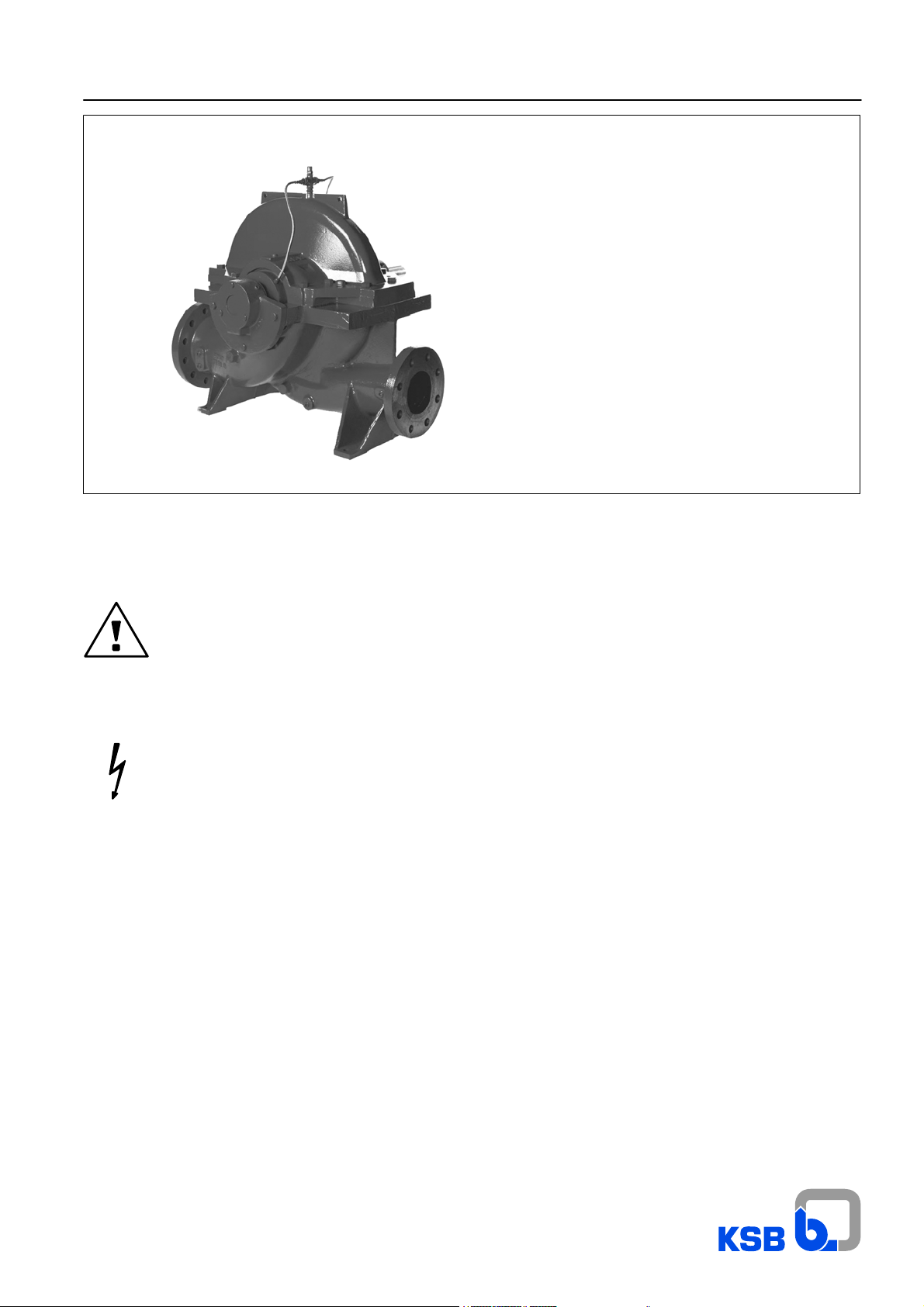
Omega1384.8/4--10
Volute casing pump
with radial impeller
Pump set
Horizontal installation -- 3 E
These operating instructions contain fundamental information and precautionary notes.
Please read the manual thoroughly prior to installation of unit, electrical connection and
commissioning. It is imperative to comply with all other operating instructions referring to
components of individual units.
Any work on the unit must only be carried out with the electrical connections (incl. control cable)
disconnected (or unplugged). Make sure that the pump set cannot be switched on accidentally.
Ident--No.: 01 059 616
Omega
For usage in hazardous locations
refer to supplementary operating
instructions 1387.81.
2

Omega
Contents Page
1 General 4...............................................................................
2 Safety 4................................................................................
2.1 Marking of Instructions in the Manual 4.........................................................
2.2 Personnel Qualification and Training 4..........................................................
2.3 Non--Compliance with Safety Instructions 4.....................................................
2.4 Safety Awareness 4..........................................................................
2.5 Safety Instructions for the Operator / User 5.....................................................
2.6 Safety Instructions for Maintenance, Inspection and Installation Work 5.............................
2.7 Unauthorized Modification and Manufacture of Spare Parts 5......................................
2.8 Unauthorized Modes of Operation 5............................................................
3 Transport and Interim Storage 5..........................................................
3.1 Transport 5.................................................................................
3.2 Interim Storage / Preservation 6...............................................................
4 Description of the Product and Accesories 6..............................................
4.1 Technical Specification 6.....................................................................
4.2 Designation 7...............................................................................
4.3 Design Details 7.............................................................................
4.4 Types of Installation 7........................................................................
4.5 Accessories (optional) 7......................................................................
4.6 Dimensions and Weights 7....................................................................
5 Installation at Site 7.....................................................................
5.1 Safety Regulations 7.........................................................................
5.2 Checks to Be Carried out Prior to Installation 7..................................................
5.3 Installing the Pump / Unit 8....................................................................
5.4 Connecting the Piping 8......................................................................
5.5 Final Check 8...............................................................................
6 Commissioning, Start--up / Shutdown 9...................................................
6.1 Commissioning 9............................................................................
6.2 Shaft Seal 9................................................................................
6.3 Venting 9...................................................................................
6.4 Commissioning 9............................................................................
6.5 Shutdown / Storage / Preservation 10...........................................................
6.6 Returning to Service after Storage 10............................................................
7 Maintenance / Repair 10...................................................................
7.1 General Instructions 10........................................................................
7.2 Maintenance / Inspection 11...................................................................
7.3 Dismantling 11...............................................................................
7.4 Reassembly 12...............................................................................
7.5 Instructions for Replacing Subassemblies 14.....................................................
7.6 Monitoring schedule 15........................................................................
8 Special Instructions for Subassemblies (Shaft Seal Variants) 16..............................
8.1 Gland packing 16.............................................................................
8.2 Mechanical Seal Variants (Mech. Seal Size / Pump Size Combinations) 17...........................
9 Spare Parts 32...........................................................................
10 Forces and Moments 34...................................................................
11 Trouble--Shooting 35......................................................................
11.1 General 35...................................................................................
11.2 Trouble--shooting Table 36.....................................................................
12 Routine Maintenance and Inspection Intervals 40...........................................
13 Appendix 41.............................................................................
3
Omega
1 General
This KSB pump has been developed in accordance with
state--of--the--art technology; it is manufactured with utmost care and subject to continuous quality control.
These operating instructions are intended to facilitate familiarization with the pump and its designated use.
The manual contains important information for reliable, proper
and efficient operation. Compliance with the operating instructions is of vital importance to ensure reliability and a long service life of the pump and to avoid any risks.
These operating instructions do not take into account local regulations; the operator must ensure that such regulations are
strictly observed by all, including the personnel called in for installation.
This pump / unit must not be operated beyond the limit values
specified in the technical documentation for the medium handled, capacity, speed, density, pressure, temperature and motor
rating. Make sure that operation is in accordance with the in structions laid down in this manual or in the contract documentation.
The name plate indicates the type series / size, main operating
data and works / series number; please quote this information
in all queries, repeat orders and particularly when ordering
spare parts.
If you need any additional information or instructions exceeding
the scope of this manual or in case of damage please contact
KSB’s nearest customer service centre.
2 Safety
These operating instructions contain fundamental information
which must be complied with during installation, operation and
maintenance. Therefore this operating manual must be read
and understood both by the installing personnel and the responsible trained personnel / operators prior to installation and
commissioning, and it must always be kept close to the location
of operation of the machine / unit for easy access.
Not only must the general safety instructions laid down in this
chapter on ”Safety” be complied with, but also the safety in structions outlined under specific headings.
2.1 Marking of Instructions in the Manual
The safety instructions contained in this manual whose non-observance mightcause hazards to persons are specially marked with the general hazard sign, namely
The word
Caution
is used to introduce safety instructions whosenon--observance
may lead to damage to the machine and its functions.
Instructions attached directly to the machine, e.g.
· arrow indicating the direction of rotation
· markings for fluid connections
must always be complied with and be kept in perfectly legible
condition at all times.
2.2 Personnel Qualification and Training
All personnel involved in the operation, maintenance, inspection and installation of the machine must be fully qualified to
carry out the work involved.
Personnel responsibilities, competence and supervision must
be clearly defined by the operator. If the personnel in question
is not already in possession of the requisite know--how, appropriate training and instruction must be provided. If required, the
operator may commission the manufacturer / supplier to take
care of such training. In addition, the operator is responsible for
ensuring that the contents of the operating instructions are fully
understood by the responsible personnel.
2.3 Non--Compliance with Safety Instructions
Non--compliance withsafety instructionscan jeopardizethe safety of personnel, the environment and themachine itself. Non-compliance with these safety instructions will also lead to forfeiture of any and all rights to claims for damages.
In particular, non--compliance can, for example, result in:
· failure of important machine / unit functions
· failure of prescribed maintenance and servicing practices
· hazard to persons by electrical, mechanical and chemical
effects
· hazard to the environment due to leakage of hazardous
substances
2.4 Safety Awareness
It is imperative to comply with the safety instructions contained
in this manual, the relevant national health and safety regulations and the operator’s owninternal work,operation and safety
regulations.
safety sign in accordance with DIN 4844 -- W9.
The electrical danger warning sign is
safety sign in accordance with DIN 4844 -- W8.
4
Omega
2.5 Safety Instructions for the Operator / User
Any hot or cold components that could pose a hazard must
·
be equipped with a guard by the operator.
· Guards which are fitted to prevent accidental contact with
moving parts (e.g. coupling) must not be removed whilst the
machine is operating.
· Leakages (e.g. at the shaft seal) of hazardous media hand-
led (e.g. explosive, toxic, hot) must be contained so as to
avoid any danger to persons and the environment. Pertinent legal provisions must be adhered to.
· Electrical hazards must be eliminated. (In this respect refer
to the relevant safety regulations applicable to different
countries and/or the local energy supply companies.)
2.6 Safety Instructions for Maintenance,
Inspection and Installation Work
The operator is responsible for ensuring that all maintenance,
inspection and installation work be performed by authorized,
qualified specialist personnel who are thoroughly familiar with
the manual.
Work on the machine must be carried out only during standstill.
The shutdown procedure described in the manual for taking the
machine out of service must be adhered to without fail.
Pumps or pump units handling media injurious to health must
be decontaminated.
Immediately following completion of the work, all safety--relevant and protective devices mustbe re--installed and/or re--activated.
Please observe all instructions set out in the chapter on ”Commissioning” before returning the machine to service.
3 Transport and Interim Storage
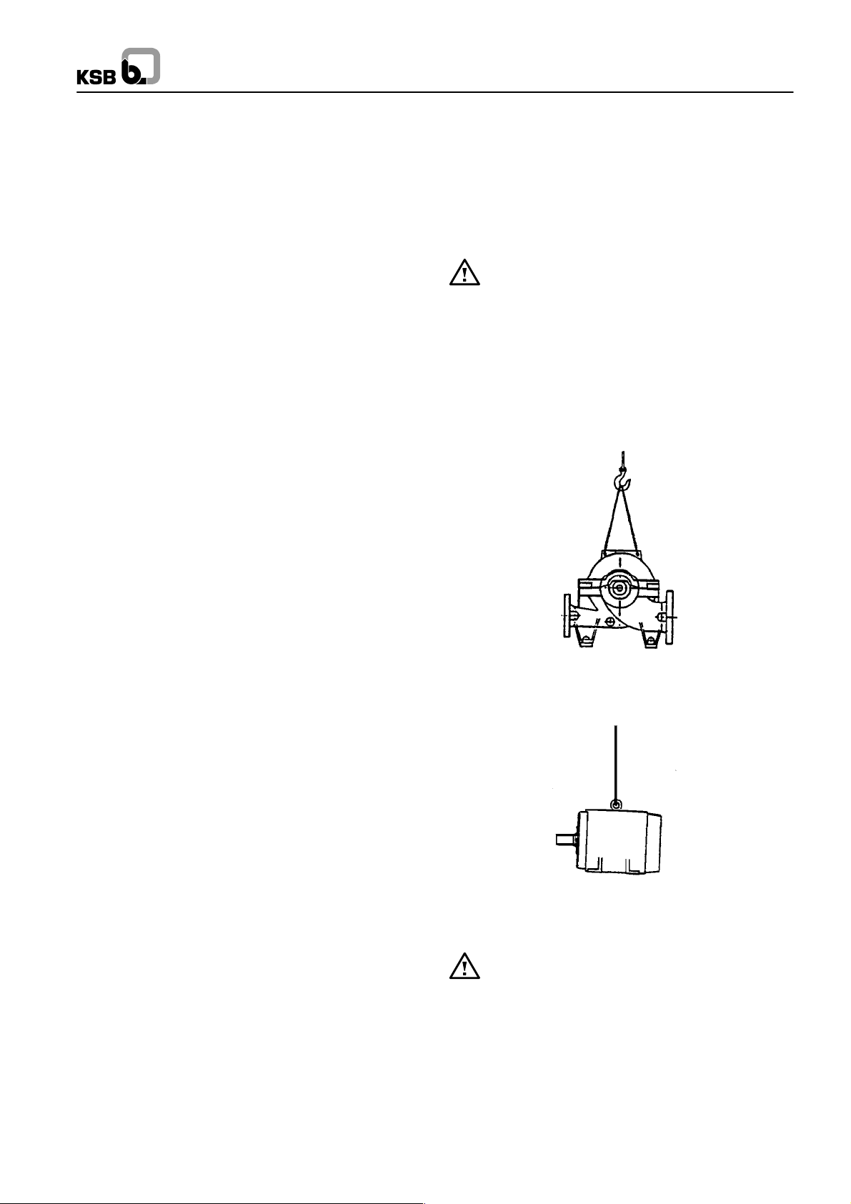
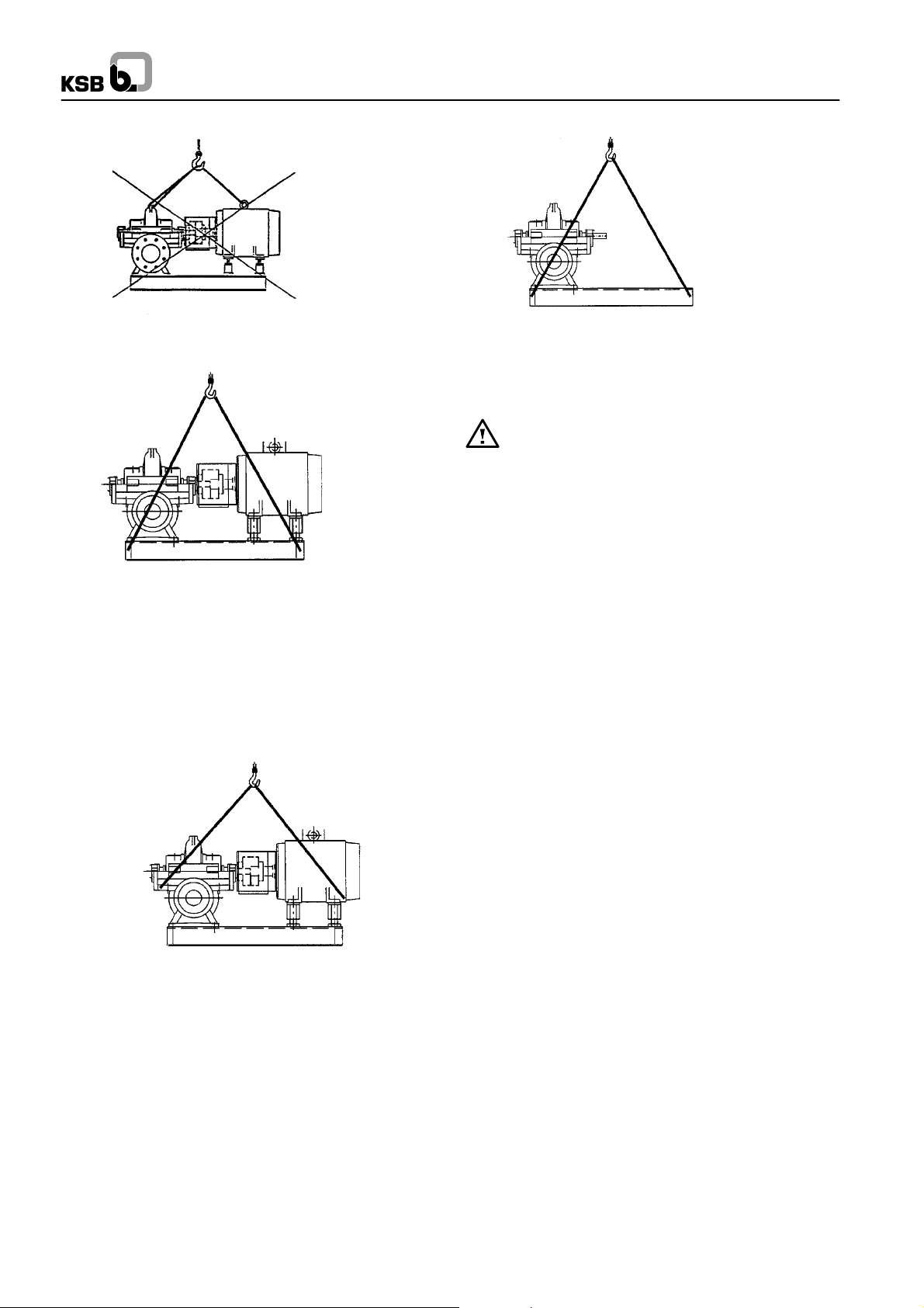
3.1 Transport
Transport of the unit requires proper preparation and handling.
Always make sure that the pump or the unit remains in horizontal position during transport and cannot slip out of the transport
suspension arrangement. Do not use lifting slings on the free
shaft end of the pump or on the motor eyebolt.
Also make sure that the coupling guard is not damaged
by the sling arrangement.If the pump / unit slips out of
the suspension arrangement, it may cause personal injury and damage to property.
Transport in horizontal position is recommended in all cases,
since this ensures stable positioning of the unit without any risk
of accident, whatever the method of transport, e.g. road, rail or
ship, etc.
For transport purposes the unit shall be securedon suitable pallets or sleds. All loose and movable parts must be secured.
2.7 Unauthorized Modification and Manufacture
of Spare Parts
Modifications or alterations of the machine are only permitted
after consultation with the manufacturer. Original spare parts
and accessories authorized by the manufacturer ensure safety.
The use of other parts can invalidate any liability of the manufacturer for consequential damage.
2.8 Unauthorized Modes of Operation
The warranty relating to the operating reliability and safety of
the pump / unit supplied is only valid if the machine is used in
accordance with its designated use as described in section 1
of these operating instructions. The limits stated in the data
sheet must not be exceeded under any circumstances.
Fig.1: Transport of pump (Fig.0)
Fig.2: Transport of motor
The motor eyebolts must only be used for lifting the motor alone, never for lifting the complete unit.
5
Omega
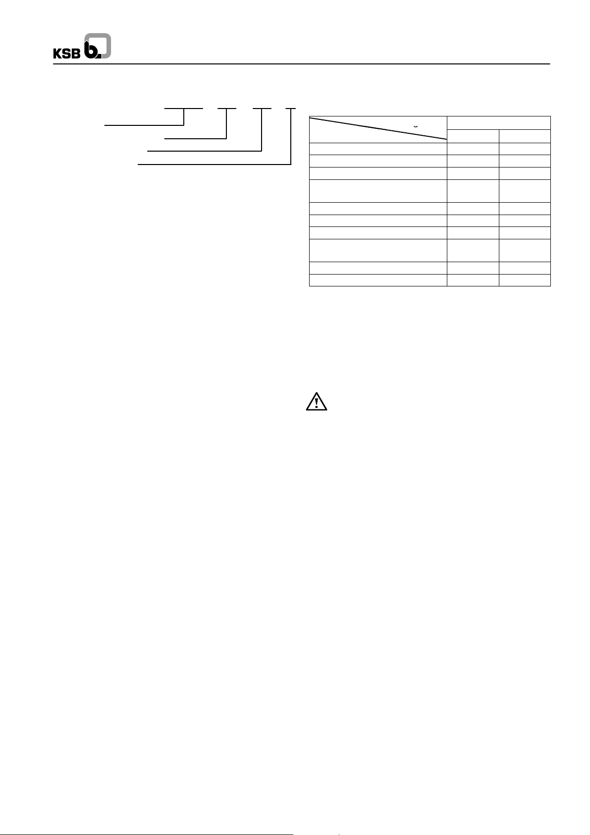
Fig.3: Never transport the unit as shown above!
Fig.4a: Transport of complete unit
(horizontal installation type 3E)
-- up to motor size 280 (IEC standard)
-- or up to a total weight of 1500 kg
Observe angles of pull when lifting.
Angle of pull > 90_ not permitted.
Use two separate sets of lifting slings!
Fig.4c: Transport of unit (without motor)
-- motor sizes 315 and above
-- or total weight (unit) of 1500 kg and above
Safe transport in horizontal position mustbe ensured by
suitable transport facilities. Make sure the pump cannot
slip out of the transport arrangement.
3.2 Interim Storage / Preservation
When the unit is temporarily put into storage, only the wetted
low alloy components, e.g. JL1040 (GG--25) must be preserved. Commercially available preservatives can be used for this
purpose. Please observe the manufacturer’s instructions for
application / removal.
4 Description of the Product and
Accesories
4.1 Technical Specification
Design
The KSB pump of the Omega series is a horizontally installed,
single--stage, axially split volute casing pump with double--entry radial impeller.Connection flanges are manufactured according to EN, DIN, ISO, BS or ASME, as preferred.
Fig.4b: Transport of complete unit
-- up to motor size 280 (IEC standard)
-- or up to a total weight of 1500 kg
6
Fields of application
In waterworks, irrigation and drainagepumping stations, power
stations, for industrial water supply, dock installations, fire extinguishing systems, refineries, pipelines and tank farms, also
for handling crude oil and refinery intermediates
Omega
g
4.2 Designation
Omega XXX XXX X
Type series
Discharge nozzle DN mm
Nominal impeller dia.
Impeller type (A,B,C)
4.3 Design Details
4.3.1 Pump Casing
Axially split volute casing with replaceable casing wear rings.
Suction and discharge nozzles in lower half of casing are at the
same level (inline version).
4.3.2 Impeller
The double--entry radial impeller is manufacturedfor the operating data provided in each case. Also with impeller wear rings,
if requested.
In double--entry radial impellers the axial thrust is largely balanced.
4.3.3 Pump Shaft
The shaft is fully sealed against the liquidbeing pumped.Shaft -protecting sleeves are fitted in the seal area.
4.3.4 Shaft Seal
The shaft seals at the drive end and non--drive end are gland
packings or mechanical seals, as requested.
4.3.5 Bearings and Lubrication
The pump is fitted with covered deep--groove ball bearings
which are grease--lubricated for life.
The fixed bearing at the non--drive end is located on a bush to
permit rapid changing without removing the rotor or upper half.
4.4 T ypes of Installation
The pump set is installed in configuration 3E -- horizontal installation, direct--coupled (see appendix).
4.5 Accessories (optional)
The following accessories are available:
Configuration Omega
Accessories Fig.0 3E
Motor -- -- x1)
Baseplate/baseframe -- -- x1)
Coupling and coupling guard -- -- x1)
Sealing and flushing water pi-
ping
Set of pressure gauges x x
Cyclone separator with pipework x x
Vent valve (manual or automatic) x x
Temperature sensor for rolling
element bearings (PT 100)
Signal transmitter for PT 100 x x
Drain line x x
2
) included in standard scope of supply
x x
x x
4.6 Dimensions and Weights
For dimensions and weights please refer to the tables in the appendix.
5 Installation at Site
5.1 Safety Regulations
Electrical equipment operated in ”zone 1” hazardous
locations must comply with the explosion protection
regulations. This is indicated on the motor rating plate.
If the equipment is installed in hazardouslocations, the applicable local explosion protection regulations and the regulations of
the test certificate supplied with the equipment and issued by
the responsible approval authorities must be observed and
complied with.
The test certificate must be kept close to the location of operation for easy access (e.g. foreman’s office).
5.2 Checks to Be Carried out Prior to
Installation
All structural work required must have been prepared in accordance with the dimensions and loads stated in the dimension
table / installation plan.
The concrete foundations shall have sufficient strength
(min. BN 25) to ensure safe and functional installation in
accordance with DIN 1045 or equivalent standards.
Make sure that the concrete foundation has set firmly before
placing the unit on it. Its surface shall be truly horizontal and
even.
7
Omega
5.3 Installing the Pump / Unit
Caution Caution
Before setting up the pump, check the
operating data. Ensure that the data on the
5.4 Connecting the Piping
name plate matches the data in the order and the system data,
e.g. operating voltage, frequency, pumped liquid temperature
etc.
Suction lift lines shall be laid with a rising slope towards the
pump and suction head lines with a downward slope towards
the pump. The pipelines shall be anchored in close proximity to
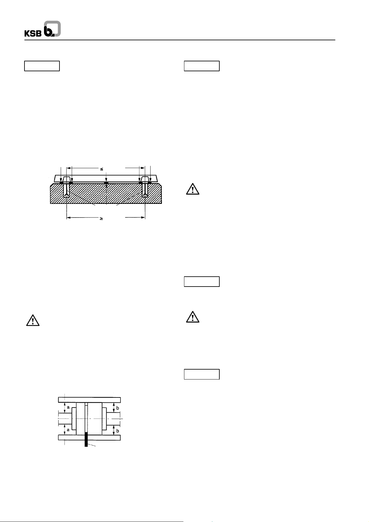
After placing the pump on the foundation, align it with the help
of a spirit level. Shims shall be fitted between the baseplate and
the foundation itself; they shall always beinserted to the left and
right of the foundation bolts and in close proximity to these
bolts. For a bolt--to--bolt clearance of more than 1000 mm, additional shims shall be inserted halfway between the adjoining
holes. All shims must lie perfectly flush.
the pump and connected without transmitting any stresses or
strains. Their weight must not exert any load on the pump. With
short pipelines, the nominal diameters shall be at least equal to
the nominal diameters of the pump nozzles. For long pipelines
the most economical nominal diameter has to be determined
from case to case.
Any additional loads on the discharge and suction nozz-
les, e.g. caused by:
Shim Shim Shim
1000
Weight of the water--filled pipes, changes in the length of pipes
owing to temperaturefluctuations, reactionforces due to unbra-
ced expansion joints must not exceed the values stated in the
installation plan.
Foundation bolts
1000
The flange covers on the pump suction and discharge nozzles
must be removed prior to installation in the piping.
Fig.5: Fitting required shims
Insert the foundation bolts and set them into the foundation
using concrete. When the concrete has set, align the baseplate
as described in section 5.3.2 and tighten the foundation bolts
evenly and firmly. Then grout the baseplateusing lowshrinkage
concrete, making sure no cavities remain.
5.3.1 Removing Rotor Lock
5.4.1 Auxiliary Connections
The locations of the auxiliary connections (sealing liquid, flus-
hing liquid, etc.) are indicated on the installation plan or piping
layout (see appendix).
Please refer to the appendix fordetailed assembly instructions.
Caution
This is not necessary for a horizontally installed pump, since no
locking device is fitted.
5.3.2 Aligning the Pump / Drive
5.4.2 Coupling Guard
Improper alignment of the unit can cause damage to
both the coupling and the unit itself!
A pump set inhorizontal installation type 3E is correctly aligned,
guard. If the customerspecifically requests not to includea cou-
pling guard in our delivery, then the operator must supply one.
if a straight--edge placed axially on both coupling halves is the
same distance from each shaft at all points around the circumference. In addition, the distance between the two coupling hal ves must remain the same all around the circumference. Use
a feeler gauge, a wedge gauge or a dial micrometer to verify
(see fig. 6).
straight edge
5.5 Final Check
Re--check the alignment as described in section 5.3.2.
It must be easy to rotate the shaft by hand at the coupling.
Caution
Never use the pump itself as an anchorage
point for the piping.
An excessive, impermissible increase in the pipeline
forces may cause leaks on the pump where the medium
handled can escape into the atmosphere.
Danger of life when hot media are handled!
These connections are required for proper
functioning of the pump and are therefore of
vital importance!
In compliance with the accident prevention regulations
the pump must not be operated without a coupling
Check the integrity and proper functioning of all
connections.
straight edge
Fig.6: Coupling alignment, using gauge and straight edge
Special instructions see appendix
gauge
8
Omega
6 Commissioning, Start-- up /
Shutdown
Caution
from non--compliance shall not be covered by the scope of
warranty.
6.1 Commissioning
Before starting up the pump make sure that the following requirements have been checked and fulfilled:
· Has the pump been firmly bolted to the foundation?
· Have the coupling and pump unit been aligned as speci-
fied?
· Can the unit be easily rotated by hand at the coupling?
(Carry out at least one full rotation)
· Are the pipes properly fitted?
· Has the coupling guard been fitted?
· Have staff been informed about sources of danger and
measures been taken to comply with the accident prevention regulations?
· Correct start--up procedure for suction lift operation.
· Is the unit protected against overload (appropriate safety
valve)?
· Have the seals been fitted as described in the appendix?
· Have any additional devices been prepared and fitted as
specified in the appendix?
· Has the pump been vented as specified in section 6.3.?
Compliance with the following requirements is
of paramount importance. Damage resulting
Correct direction of rotation:
The direction of rotation must correspond to the direction indicated by the arrow on the pump. This can be verified by switching the pump on and then off again immediately.
Before checking the direction of rotation make sure that
there is no foreign matter in the pump casing.
Never put your hands or any other objects into the pump!
6.4.2 Start--up
Caution
If a shut--off valve is fitted in the suction line, open it fully.
All additional connections for flushing or sealing liquid etc., if fitted, must be opened fully and the flow must be checked.
Switch on the motor.
As soon as the pump starts to deliver -- this can be recognised
by the rising gauge pressure -- slowly open the discharge--side
gate valve fully.
Caution
otherwise inadmissible temperature rise occurs resulting in
damage.
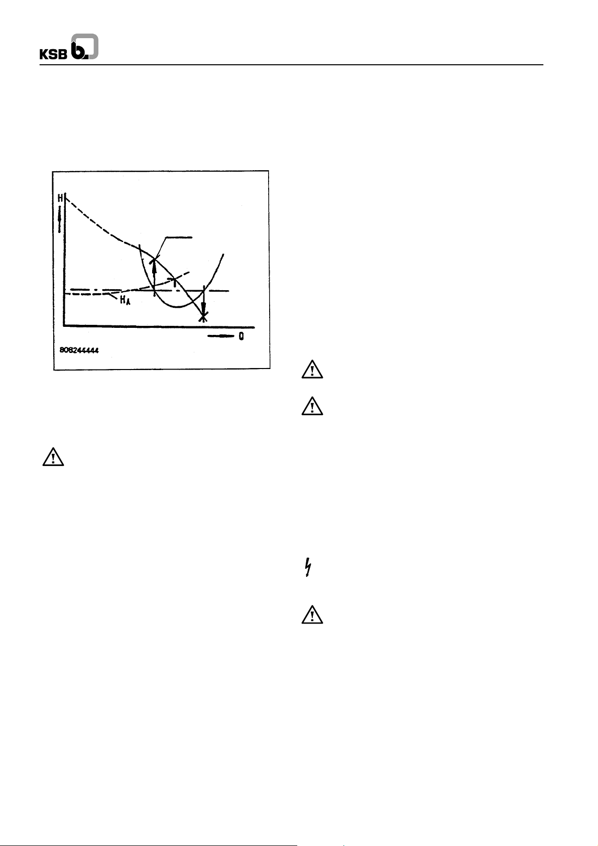
6.4.3 Pump Operating Range
The flow rate ”Q” adjusts itself automatically to the delivery
head according to the H--Q characteristic. The pump’s permitted operating range is subject to limits, which have separate
causes.
If a non--return valve is not fitted at the di -scharge--side, close the discharge--side
gate valve.
The pump may operate against the closed gate
valve only during start--up and shutdown, as
6.2 Shaft Seal
For commissioning the shaft seal please refer to section 8.1 /
8.2. If the pump has been out of service for a prolonged period,
the measures specified in section 6.6 must be carried out.
6.3 Venting
Before start--up, the pump and the pipes must be vented and
filled with the liquid to be pumped. This is done at the vent plug
on the casing (903). For suction lift operation, the pump must
also be evacuated, i.e. a vacuum must be produced.
6.4 Commissioning
6.4.1 Checking the Direction of Rotation
Caution
paramount importance.
If running in the wrong direction of rotation, the pump c annot reach its duty point; vibrations and overheating will be the consequence. The unit or the shaft seal might be damaged.
For trouble--free operation of the pump, the
correct direction of rotation of the impeller is of
1. Part load operating limit for low flow rate
This limit is indicated in the H--Q characteristic by Q
discontinuation of the characteristic curve.
Caution
in this range causes greatly increased mechanical loads which
the components cannot withstand.
Brief passage through the critical range is permissible, e.g. during start--up
2. NPSH--related limits in the part load and overload ranges
These two limits are determined by the ratio of NPSH
NPSH
available
It is not permissible to operate the pump in the
range from Q=0 to Q
. They are determined as follows:
Prolonged operation
min.
min
required
or by the
to
9
Omega
The intersections of NPSH
required
and NPSH
available
are projected onto the H--Q characteristic, where they indicate theoperating limits (refer to the diagram below). Checking of the
NPSH--related operating limit is notnecessary for operating the
pump under design conditions. If system--related changes occur, an NPSH check must be carried out. If necessary, consult
the nearest after--sales service centre.
Q
min
NPSH
required
NPSH
available
6.4.4 Shutdown
Close the shut--off element in the discharge line. If the discharge line is equipped with a check valve, the shut--off ele ment may remain open, provided there is back pressure in the
line.
The shut--off element in the suction line must not be closed when switching off the pump. Switch off the motor,
making sure that the unit runs smoothly down to a standstill.
Depending on the system the pump shall have an adequate after--run period -- with the heat source switched off -- to allow the
medium handled to cool down sufficiently to avoid any heat
build--up within the pump.
In the case of prolonged shutdown, the shut--off element in the
suction line has to be closed.
Close the auxiliary connections.
In the event of frost and / or prolonged shutdowns, the pump
must be drained or otherwise protected against freezing.
6.5 Shutdown / Storage / Preservation
Each KSB pump leaves the factory carefully assembled.If commissioning is to take place some time after delivery, we recommend that the following measures be taken for pump storage.
6.5.1 Storage of New Pumps
· New pumps are supplied by our factory duly prepared for
storage.
Maximum protection for up to 12 months, if the pump is properly stored indoors.
· Store the pump in a dry location.
6.5.2 Measures to be Taken for Prolonged Shutdown
1. The pump remains installed; periodic check of operation
In order to make sure that the pump is always ready for instant
start--up and to prevent the formation of deposits within the
pump and the pump intake area, start up the pump set regularly
once a month or once every 3 month for a short time (approx.
5 minutes) during prolonged shutdown periods. Prior to an operation check run ensure that there is sufficient liquid available
for operating the pump.
2. The pump is removed from the pipe and stored
Before putting the pump into storage carry out all checks specified in sections 7.1 to 7.4. Then apply appropriate preservatives:
· Spray--coat the inside wall of the pump casing, and in parti-
cular the impeller clearance areas, with a preservative.
Spray the preservative through the suction and discharge
nozzles. It is advisable to close the nozzles (for ex. with plastic caps or similar).
6.6 Returning to Service after Storage
Before returning the pump to s ervice carry out all checks and
maintenance work specified in sections 5.1 and 5.2.
In addition, the instructions laid down in section 6.1
”Commissioning” and section 6.4.3 ”Operating limits”
must be observed.
Upon completion of the work, all safety--related and protective equipment must be properly refitted and / or reactivated before starting the pump set.
7 Maintenance / Repair
7.1 General Instructions
The operator is responsible for ensuring that all maintenance,
inspection and installation work is carried out by authorized,
duly qualified staff who are thouroughly familiar with these operating instructions.
A regular maintenance schedule will help avoid expensive repairs and contribute to trouble--free, reliable operation of the
pump with a minimum of maintenance expenditure and work.
Work on the pump and the motor must only be c ar-
ried out with the electrical connections disconnected. Make sure that the pump set cannot be switched on accidentally (danger of life!).
Pumps handling liquids posing health hazards must be
decontaminated. When draining the medium see to it
that there is no risk to persons or the environment. All relevant
laws must be adhered to (danger of life!).
10
Omega
7.2 Maintenance / Inspection
7.2.1 Supervision of Operation
Caution
Prolonged operation against a closed shut--off element
is not permitted in order to prevent the medium handled
from heating up.
At room temperatures of up to 30 _C(86_F) the bearing temperature shall be below 90 _C (194 _F). At higher room tempera tures, the bearing temperature shall be below100 _C (212 _F).
During pump operation the shut--off element in the inlet
line must not be closed.
Any stand--by pumps installed shall be switched on and then
immediately off again once a week to keep them operational.
Attention shall be paid to the correct functioning of the auxiliary
connections.
Caution
time. See section ”Coupling”.
If an external supply of sealing, flushing or lubricating liquid is
used, make sure supply pressure is 1.0 to 2.0 bar higher than
pressure at the suction nozzle.
On pumps fitted with a gland packing the packing must drip
slightly during operation. The gland cover should therefore only
be gently tightened. (See section 8 ”Special instructions for
subassemblies, shaft seal variants”).
7.2.2 Shaft Seal Maintenance
For required maintenance work on gland packings please refer
to section 8.1. ”Shaft seal”. Mechanical seals are maintenance--free.
7.2.3 Bearing Maintenance
The bearings are maintenance--free and greased for life. No
re--lubrication is required.
The pump shall run quietly and free from
vibrations at all times. The pump must neverbe
allowed to run dry.
If the flexible coupling elements begin to show
signs of wear, they must be replaced in due
7.3 Dismantling
Before dismantling, secure the pump so as to makesure
it cannot be switched on accidentally. The shut--off elements in the suction and discharge lines must be closed. The
pump must have cooled down to ambient temperature, pump
pressure must be released and the pump must be drained.
Dismantling and reassembly must always be carried out in ac cordance with the relevant sectional drawing.
7.3.1 Fundamental Instructions and
Recommendations
Repair and maintenance work to the pump must only be carried
out by specially trained personnel, using original spare parts.
Observe the safety regulations laid down. Any work on the motor shall be governed by the specifications and regulations of
the respective motor supplier.
Dismantling and reassembly must always be carried out in ac cordance with the relevant general drawing. The general drawing and other relevant documents are found in the annex. The
dismantling sequence can be derived from the general drawing.
In case of damage you can always contact our nearest customer service centre.
7.3.2 Preparations for Dismantling
The pump is designed so that the complete rotor can be removed in the sequence described below without removing the suction or discharge pipe or disturbing the alignment of the pump
unit:
· Close the suction anddischarge--side gate valvesand drain
the pump by opening the drain plug (903.01 bottom) and
vent plug (903.01 top).
· Remove any pipes between additional equipment and the
pump.
· Removethe coupling guard. Decouple pump--side coupling
half as described in the appendix.
· Loosen and push back the seal cover (471), if a mechanical
seal is fitted.
· Undo the flange screws (901.01 / 901.02) and separate the
upper casing half (105.02) from the lower casing half
(105.01) with the aid of the forcing screws. Remove with lifting gear. The interior of the pump (impeller with casing
wear rings, shaft seal) is now accessible for inspection.
· Remove the screwed connection (901.04) betweenbearing
housing (350.01) and bearing brackets. Also undo the nuts
(920.05) and bolts (901.07) which secure the bearing cover
(360).
· Press the bearing housing out of the recesses and lift the
rotor out of the lower casing half. For further disassembly,
place securely in horizontal position.
· Pull off the bearing housing of the fixed bearing (opposite
the drive end).
· Undo and remove the keywayed nuts (920.03).
· Remove the deep--groove ball bearing (312) with bush
(520) from the shaft.
· Remove the bearing cover (360).
· Remove the V--ring (412.02) from the shaft--protecting
sleeve (524.01).
· Pull off the shaft--protecting sleeve (524.01).
· Remove the shaft seal housing (441).
· The impeller (234) is located with a sliding fit on the shaft
and can normally be removed easily. In case of difficulty, it
can be loosened by gently tapping the hub with a wooden
hammer.
· Remove the second shaft protection sleeve (524.01) com-
plete with the shaft seal housing (441), if fitted.
· Remove the coupling half.
· Pull off the bearing housing (350.01).
· Remove the circlip (932) and pull off the deep--groove ball
bearing (321).
11
7.4 Reassembly
Reassembly is effected in reverse order to dismantling. For all
work on the pump unit refer to the general drawing, in conjunction with the list of components, for orientation.
The rules of sound engineering practice and also the instructions for removal and installation of shaft seal, bearings, impeller wear rings and casing wear rings (sections 7.5.1 and 7.5.2)
must be observed.
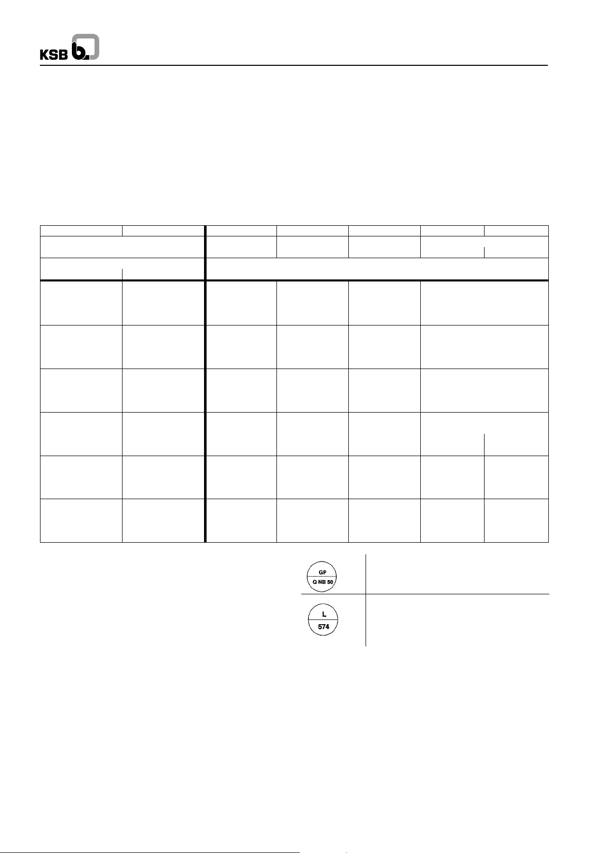
The tightening torques indicated for nuts and bolts shall be observed. The table below indicates the tightening torques for
threads depending on the materials used.
Property class (Material) 8.8 10.9 A.-50 A.-70 1.4462
0,2% yield stress 640 900 210 450
R
p02
in N/mm
2
Metric ISO threads Tightening torque
coarse--pitch- fine--pitch- M
M4 3,1 4,4 1,0 2,15
M5 6,1 8,7 2,00 4,25
M6 10,4 14,9 3,40 7,30
M8 25,2 36,1 8,30 17,7
M10 49,5 71,0 16,2 34,8
M12 85,2 122,2 28,0 59,9
M16 211 302,7 69,2 148
M20 412 591,9 135 290
M24 710 1019,6 233 276 500
M27 1050 1501,3 343 409 736
M30 1420 2036,4 466 554 1000
M33 1940 2779,4 636 -- -- 1360
M36 2480 3552,3 812 -- -- 1740
1
) Nominal values to DIN ISO 898 Part 1, DIN 267 Part 11 and DIN 267 Part 18
1
) 250 450
in Nm
A
M8x1 27,2 39,0 8,90 19,1
M10x1,25 52,5 75,4 17,3 36,9
M12x1,5 89,5 128,5 29,4 62,9
M12x1,25 93,9 134,7 30,8 66,0
M16x1,5 226 324,7 74,3 159
M20x1,5 461 661,0 151 324
M24x2 780 1118,6 256 305 548
M27x2 1130 1627,1 372 443 797
M30x2 1580 2269,9 519 618 1110
M33x2 2130 3062,6 700 -- -- 1500
M36x3 2630 3775,4 863 -- -- 1850
Omega
It is imperative to lock and seal the screwed connections specially marked in the general drawings.
Symbols for screwed connections to be locked and sealed:
12
ALTEMP Q NB 5 0 grease
Sealed with Loctite 574
Omega
O--rings and V--rings must be replaced and their seats on the
shaft must be cleaned. In addition, all the sealing elements
must be fitted into the respective components before installation.
For assembling the rotor, position the pump shaft (211) securely. All fits, threads and sliding fits of the shaft must be cleaned
and coated with assembly paste.
Insert the keys required for assembly into the pump shaft (211).
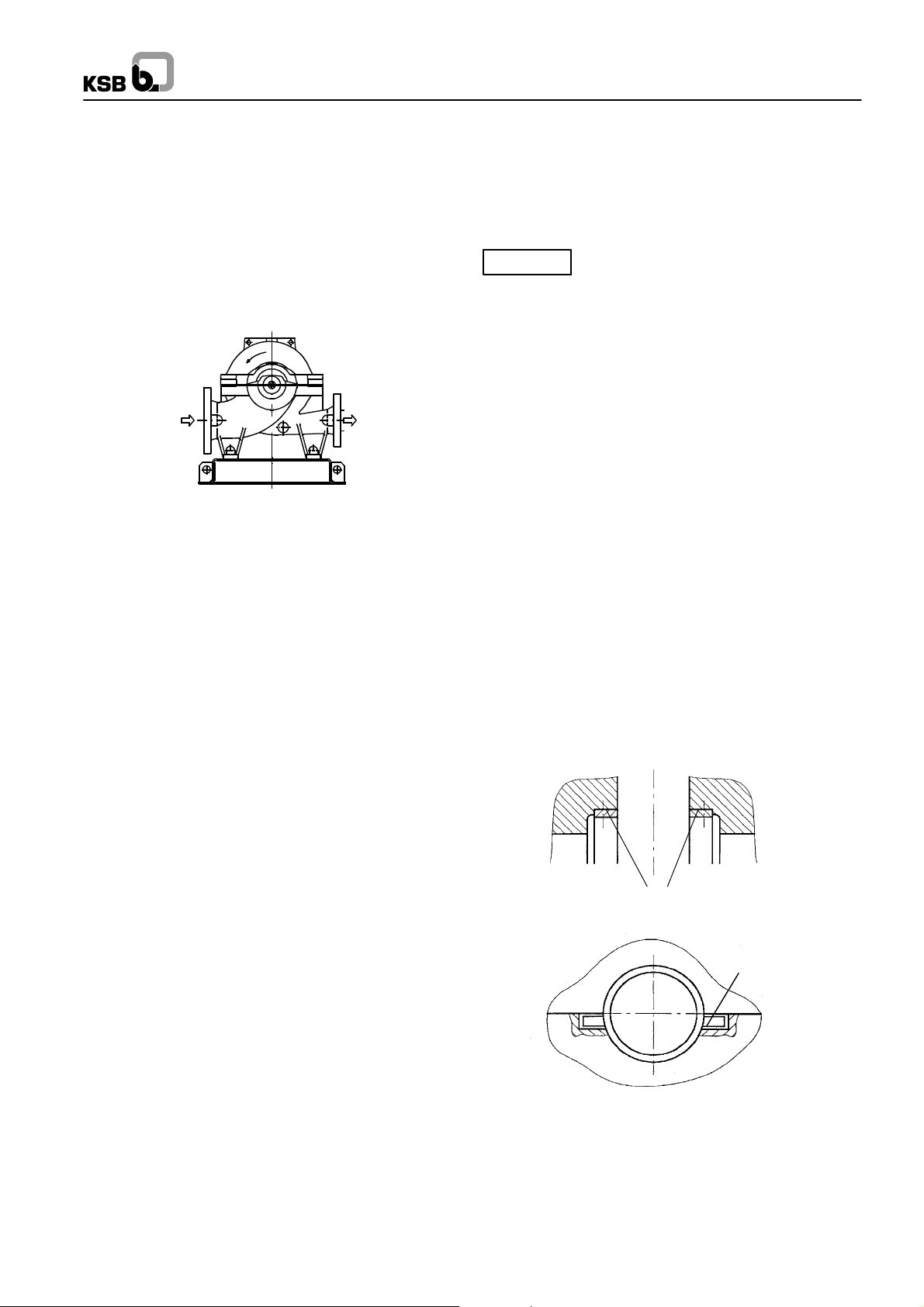
Mount the impeller (234),which has a sliding fit. When fitting the
impeller,observe the direction of rotation (see diagram below).
For assembling the casing wear rings (502), observe section
7.5.2 ”Replacing the casing wear rings”.
Put the casing wear rings onto the running surfaces of the impeller.Ensure that the bezels of the rings are on the outside (towards the bearing). Insert the pins required for fixing the casing
wear rings.
The remaining components are fitted first on the movable bearing side (i.e. the drive side) of the pump shaft.
Push the shaft protecting sleeve (524.01) onto the pump shaft
(211). Ensure that the groove provided engages in the key of
the impeller.
Push the shaft seal housing (441) onto the shaft and install
the shaft seal as described in section 8.1, ”Gland packing”.
Slip on V--ring (411.01).
Insert the radial shaft seal ring (421.02) into the bearing cover
(360) and push the bearing cover over the shaft.
Heat the deep--grooved ball bearing (321) and fit it onto the
pump shaft (211). It is essential to avoid one --sided pressure or
hammer blows on the outer races. The bearing is secured by
the disc (550.01) and the circlip (932).
To fit the shaft protecting sleeve (524.01), shaft seal housing
(441), V--ring (411.01) and bearing cover (360) at the non--drive
end, proceed as described above for the drive side.
Heat the deep--groove ball bearing (321) and fit it onto the
sleeve (520).
Push the sleeve (520) with deep--groove ball bearing (321)onto
the pump shaft (211) with key (940.01) inserted.
Tension the rotor parts elastically with keywayed nut (920) and
cup spring (950). For this purpose tension the cup spring (950)
to blocking point and then undo the keywayed nut (920) again
by half a turn (180_).
Caution
This measure is essential to compensate for
differences in thermal expansion between the
pump shaft (211) and the components fitted on it.
Rotor assembly is now complete.
Insert the rotor into the pump casing.
Apply Loctite 574 to the casing wear ring surfaces and the sealing surfaces of the casing.
Install the rotor,making sure that the direction of rotation is correct.
Align the rotor and ensure that the fixing pins are correctly seated in the casing.
The pins (561.01) must be positioned as shown in the diagram
below.
The bearing housings (350.01) must be fastened to the bearing
brackets by means of the screwed connections (901.04), with
the sealing cap (580) inserted at the non--drive end.The seating
positions are determined by the recesses.
Fit the bearing covers.
To assemble the casing cover, apply Loctite 574 to the casing
joint surface of the lower casing half.
Tighten the flange bolts diagonally from the inside towards the
outside.
Insert the key for fitting the coupling into the pump shaft (211).
When fitting the coupling and accessories, refer to the relevant
section of the operating instructions.
Casing wear rings
(502)
561.01
13

Omega
7
0
7.5 Instructions for Replacing Subassemblies
After dismantlingas described in section 7.3.2, the casing wear
rings (502) can be removed. When fitting the rings, ensure that
7.5.1 Replacing the Shaft Seal
Proceed as described in section 8.1 and 8.2.
7.5.2 Replacing Casing Wear Rings and / or Impeller
Wear Rings
1)
The impeller clearance
clearance between impeller 234 and
casing wear ring 502 is given in the table below.
For impeller removal proceed as described in section 7.3,
their bezels are on the outside (towards the bearing). The pins
(561.01) must be positioned as shown in the diagram below.
If the impeller has not been fitted with a wear ring at the factory,
and changing the casing wear ring alone does not achieve anything close to the required impeller clearance (the impeller
neck is badly worn by clearance flows), the impeller neck must
be turned off on a lathe (contact KSB before doing so) and an
impeller wear ring fitted in addition (available as spare part).
Alternatively, a new impeller can be supplied at short notice.
”Dismantling”.
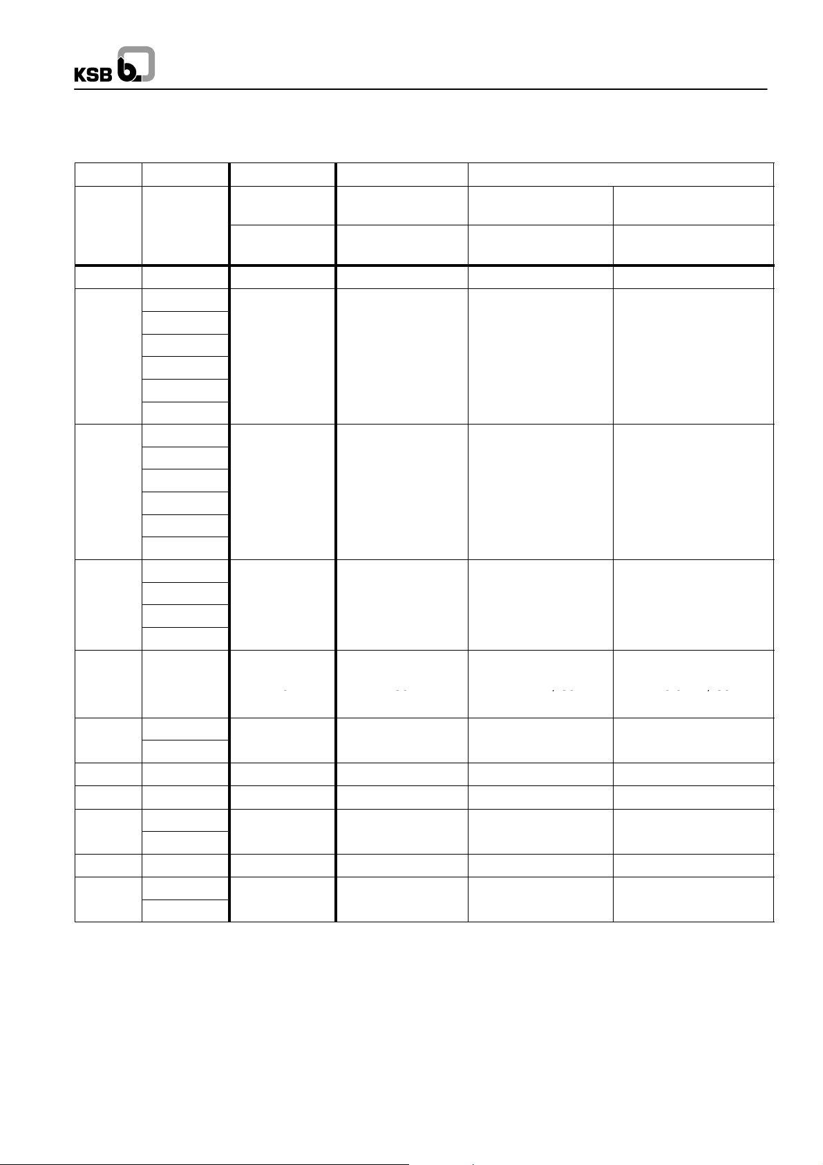
Impeller clearances and trim dimensions for impeller wear rings
Clearance (as--new) Dimensions of impeller wear ring
No. Pump
size
1 80-210 0,3 0,15 0,2 134 r6 18
2 80-270 0,3 0,15 0,2 134 r6 18
3 80-370
4 100-250
5 100-310 0,35 0,17 0,2 163 r6 22
6 100-375 0,35 0,17 0,2 163 r6 22
7 125-230 0,35 0,18 0,23 178 r6 22
8 125-290 0,35 0,18 0,23 178 r6 22
9 125-365
10 125-500
11 150-290 0,45 0,22 0,26 210 r6 30
12 150-360 0,45 0,22 0,26 210 r6 30
13 150-460 0,45 0,22 0,26 210 r6 30
14 150-605
15 200-320
16 200-420 0,5 0,24 0,28 243 r6 30
17 200-520 0,5 0,24 0,28 243 r6 30
18 200-670
19 250-370
20 250-480
21 250-600
22 300-300 70 0,5 0,24 0,28 259 r6 30
23 300-435 80 0,6 0,29 0,35 313 r6 35
24 300-560
25 300-700
26 350-360 80 0,5 0,24 0,28 294 r6 35
27 350-430
28 350-510
Shaft
unit
DW 2 D5 b
40
50
60
70
80
90
90
Nominal clea-
rance
(max. perm.)
D
2-D1
[mm] [mm] [mm] [mm] [mm]
0,3 0,15 0,2 134 r6 18
0,35 0,17 0,2 163 r6 22
0,35 0,18 0,23 178 r6 22
0,35 0,18 0,23 178 r6 22
0,45 0,22 0,26 210 r6 30
0,5 0,24 0,28 243 r6 30
0,5 0,24 0,28 243 r6 30
0,5 0,24 0,28 276 r6 30
0,5 0,24 0,28 276 r6 30
0,5 0,24 0,28 276 r6 30
0,6 0,29 0,35 313 r6 35
0,6 0,29 0,35 313 r6 35
0,6 0,32 0,37 333 r6 35
0,6 0,32 0,37 353 r6 35
Min.
clearance
Smin
Max.
clearance
Smax
b
S (min - max)
14
7.6 Monitoring schedule
For a detailed description of the pump version, components
and accessories supplied by KSB please refer to section 13 of
this operating manual.
Component monitored Action Value required
Omega
Mechanical seal
(if applicable)
Gland packing
(if applicable)
Suction side measuring instrument, ps
(if applicable)
Discharge side measuring instrument, pd
(if applicable)
Thermometer
(suction / discharge nozzle)
(if applicable)
Flushing line sight glass
(if applicable)
Vibration measurement
(if applicable)
Bearing temperature
(if applicable)
Coupling Check weekly
Drive
(if applicable)
Coupling guard Check monthly No contact permitted
Earthing connection Check monthly Connection must be fitted and marked.
Check for leakage (daily) see section 8.2 and *
Check for leakage (daily) 10 to 120 drops / min.
Check pressure (daily) *
Check pressure (daily) *
Check temperature (weekly) *
Check flushing water flow
(weekly)
Check weekly *
Check weekly Section 7.2
See manufacturer’s documentation Ensure contact--free installation
Water flows
Annex from p. 47, detailed manufacturer
information
* see list of measuring points (if applicable) in section 13,
Annex.
In the event of deviations proceed as described in the table given in section 11.2 (Trouble--shooting).
15

Omega
8 Special Instructions for
Subassemblies (Shaft Seal Variants)
The shaft seal variant supplied is shown in the purchase order
and order--processing documents.
8.1 Gland packing
The gland packings used by KSB are asbestos--free and suita ble for drinking water applications.
Installation and commissioning
Before installation, ensure that the gland space is clean (no
packing remnants or corrosion). The shaft protecting sleeve
must be bright and have no scoring. Otherwise a new shaft protecting sleeve must be used.
Cutting the packing rings to size
If moulded packing rings are not available, the rings can best
be cut to size using a special cutting gauge. If no cutting gauge
is available, take a tube with the same diameter as the shaft,
wind the packing around the tube in a spiral and cut the rings
from the spiral. We recommend a straight cut.
Installing the packing rings
Push the packing rings with the stuffing box insertinto the gland
space one by one. The joints of the packing rings must be offset
by 90_. The number of rings and the arrangement of the lantern
ring are shown in the general drawing (see appendix). After fitting all the packing rings, put on the stuffingbox insertand gland
cover and tighten them so that the packing rings adapt to the
gland space. Then loosen the gland cover again to relieve the
load on the packing. This procedure is notnecessary if moulded
packing rings are used.
Also note the following:
Leakage and temperature rise: If necessary, shut down the
pump. After a short cooling period (approx. 10 to 15 minutes)
the pump can be restarted. The necessary minimum leakage
depends on the liquid being pumped, thepressure, sliding velo city and temperature. It is approx. 10 to 120 drops per minute
(20 drops of water correspond to approx. 1 ml).
Disassembly
A packing puller must be used for pulling out the packing rings.
Maintenance
Gland packings must be repacked in accordance with the section ”Installation and commissioning” after prolonged standstill, repair work or heavy leakage. Therefore, the leakage rate
must be observed during operation, alsoto avoid possible overheating.
Commissioning
When the pump is started up,the gland must only be gently tightened (by hand). A high leakage rate (approx. 50 to 200 drops
per minute), depending on the liquid being pumped, must be accepted until the packing material has settled and has adapted
to the temperature conditions (approx. 10 to 15 minutes).
Then the gland cover must be carefully and evenly tightened to
reduce the leakage to a minimum. If there is no leakage, there
is a risk that the packing will run hot.
16
8.2 Mechanical Seal Variants (Mech. Seal Size / Pump Size Combinations)
7080M7N4/80HJ92N/80
Mechanical seal variants
No. Pump size Shaft unit Nom. mech. seal
Non--balanced Balanced
size
d
w
d for operating pres--
suresupto16bar
for operating pressures
> 16 bar
1 80 - 210
2 80 - 270
3 80 - 370
40 50 M7N4/50 HJ 92 N/50
4 100 - 250
5 100 - 310
6 100 - 375
7 125 - 230
8 125 - 290
9 125 - 365
50 60 M7N4/60 HJ 92 N/60
10 125 - 500
11 150 - 290
12 150 - 360
13 150 - 460
14 150 - 605
60 70 M7N4/70 HJ 92 N/70
15 200 - 320
16 200 - 420
17 200 - 520
18 200 - 670
70 80 M7N4/80 HJ 92 N / 80
19 250 - 370
20 250 - 480
80 90 M7N4/90 HJ 92 N/90
21 250 - 600
22 300 - 300 70 80 M7N4/80 HJ 92 N / 80
23 300 - 435 80 90 M7N4/90 HJ 92 N / 90
24 300 - 560
90 110 M74N/110 H75N/110
25 300 - 700
26 350 - 360 80 90 M7N4/90 HJ 92 N / 90
27 350 - 430
90 110 M74N/110 H75N/110
28 350 - 510
Omega
17
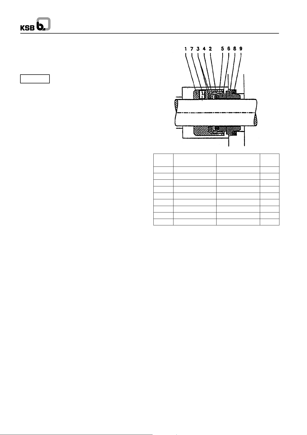
8.2.1 Mechanical Seal ”Type H7N4”
(Shaft unit d
The mechanical seal type H 7 N 4 usedis a single--acting, bi--rotational, non--balanced seal which does not require circulation
pipework in cold water applications, due to the pump design.
Caution
Installation
For the installation of the total seal assembly (mechanical seal,
seal housing) see operating instructions for the pump.
The shaft protection sleevesand also the surfaces ofthe casing
are subjected to accurate finishingprocesses with regard to the
O--ring seats, in order to achieve a complete and reliable seal.
Care must be taken during installation to keep these parts absolutely clean, to avoid the surfaces from being damaged and
prevent entry of foreign particles.
The seat ring (8) together with the relevant O--ring (9), is fitted
into the seal cover (see general drawing). The O--ring can be
lubricated for easy s liding movement. Special attention mustbe
given to ensure that pressure is applied evenly. The contact
surfaces are generally fitted dry.
In mechanical seals of the M7N4 design, the rotating assembly
is supplied as one unit, consisting of a housing and pin ( 1 + 5),
fitted spring loaded ring (6), O --ring (2), spring (3), thrust plate
(4) and grub screws (7). The grub screws (7) must be loosened
so far as to prevent them from protruding from the housing (1)
at the inner diameter. The O--ring (2) can be slightly lubricated
to facilitate assembly.
The complete rotating assembly is pushed onto the shaft protection sleeve in compliance with the installation dimensions
which are given in the mech. seal drawing,or until it reaches the
stop on the shaft protection sleeve. Finally the grub screws are
tightened and secured with LOCTITE.
40 to 80 mm)
w
Dry--running of the seal must be avoided at
all costs!
Omega
Item Description Material No. of
items
1 Housing Cr-Ni-Mo-steel 1
2 O--ring Viton 1
3 Spring Cr-Ni-Mo-steel 1
4 Thrust plate Cr-Ni-Mo-steel 1
5 Pin Cr-Ni-Mo-steel 2
6 Spring--loaded ring Si-SiC 1
7 Grub screw Cr-Ni-Mo-steel 2
8 Seat ring Si-SiC 1
9 O--ring Viton 1
Special instructions for mechanical seal assembly
· The contact faces must only be cleaned with propyl alcohol
and paper tissue.
-- Never use cleaning rags or cloth.
-- Clean carefully to remove any smears.
· Do not touch the contact faces with bare fingers.
· Never use force during mechanical seal assembly.
· Never put the spring--loaded ring and the seat ring face
down on the contact faces without the protective wrapping.
· Cover the contact face with a cardboard washer and press
the seat ring into its position slowly and evenly, lubricating
it with a generous amount of water or alcohol. Use a spacer
sleeve, if necessary. Verify that the seat ring position is nor mal to the shaft axis.
· In the mechanical seal area, the shaft shall be slightly lubri-
cated with water, alcohol or silicone grease. Sealing elements made of EP rubber must never come into contact
with mineral oil base lubricants (swelling, possibly decomposition).
18

Omega
Commissioning
Flood the pump and the seal chamber with the medium to be
handled and vent carefully. The seal is operational now.
On single --acting mechanical seals, the pressure in the seal
chamber of the pump (stuffing box) must always exceed ambient pressure, to prevent any air intake at the seal faces,
which would result in dry running and thus failure of the mechanical seal.
In all operating conditions, the product to be sealed off must
be available in liquid state at the mechanical seal, particularly
during pump start--up and shutdown. This must be ensured by
appropriate facilities on the pump (e.g. heating).
Should the mechanical seal fail, the liquid to be sealed off may
spurt out. Takesuitable precautions to prevent hazards to persons and the environment, e.g. install splash guards, wear safety goggles, etc. Proper disposal of leakage shall be arranged for and supervised by the operator.
Maintenance
Mechanical seals operated in compliance with the manual
are maintenance--free in their entire service life.
The mechanical seal should be inspected in accordance with
the plant inspection schedule.
During planned plant outage periods the spring--loaded rings
and the seat rings should be checked for visible damage in installed condition.
If the mechanical sealis inspected during plant outage,the contact faces should be re--worked.
Dismantling
For dismantling of the mechanical seal assembly please refer
to section 7.3 ”Dismantling”. Grub screws (7) and joint rings
(2+9) shall be replaced whenever the mechanical seal has
been dismantled!
Repair
If the seal needs to be repaired,alwaysreturn the complete
seal to the manufacturer. The manufacturer will know best
which parts can be re--worked andwhich parts have to be replaced to ensure an optimum sealing effect.
If repair on the spot is necessary, it should be carried out in a
clean workshop preferrably byKSB --monteurs or skilled operator staff. Spring--loaded rings, seat rings, all elastomer materials and springs should be replaced in any case.
Make sure to comply with the instructions for handling h a-
zardous substances and the applicable accident preven tion regulations when repairing, dismantling and cleaning
used mechanical seals. If you have any queries in this context
please inform yourself before commencing any repair work.
Spare parts
Only original spare parts shall be used. Non-- compliance
with this requirement entails the risk of seal malfunctions
which may jeopardize the safety of personnel and the environment.
It will also lead to forfeiture of all warranty claims.
Faults
Determine and document the nature of the fault.
In the event of a fault as evidenced by excessive leakage, observe the tendency of the leakage amount. Changes in operating conditions must be documented. If an excessive temperature rise is detected, the mechanical seal must be shut down for
safety reasons.
During the warranty period the mechanical s eal shall only be removed and dismantled with the manufacturer’s approval or under instructions of the mechanical seal manufacturer’s service
engineers.
If the fault cannot be remedied by the operator or if the cause
is unclear, please contact the KSB service center.
19
Omega
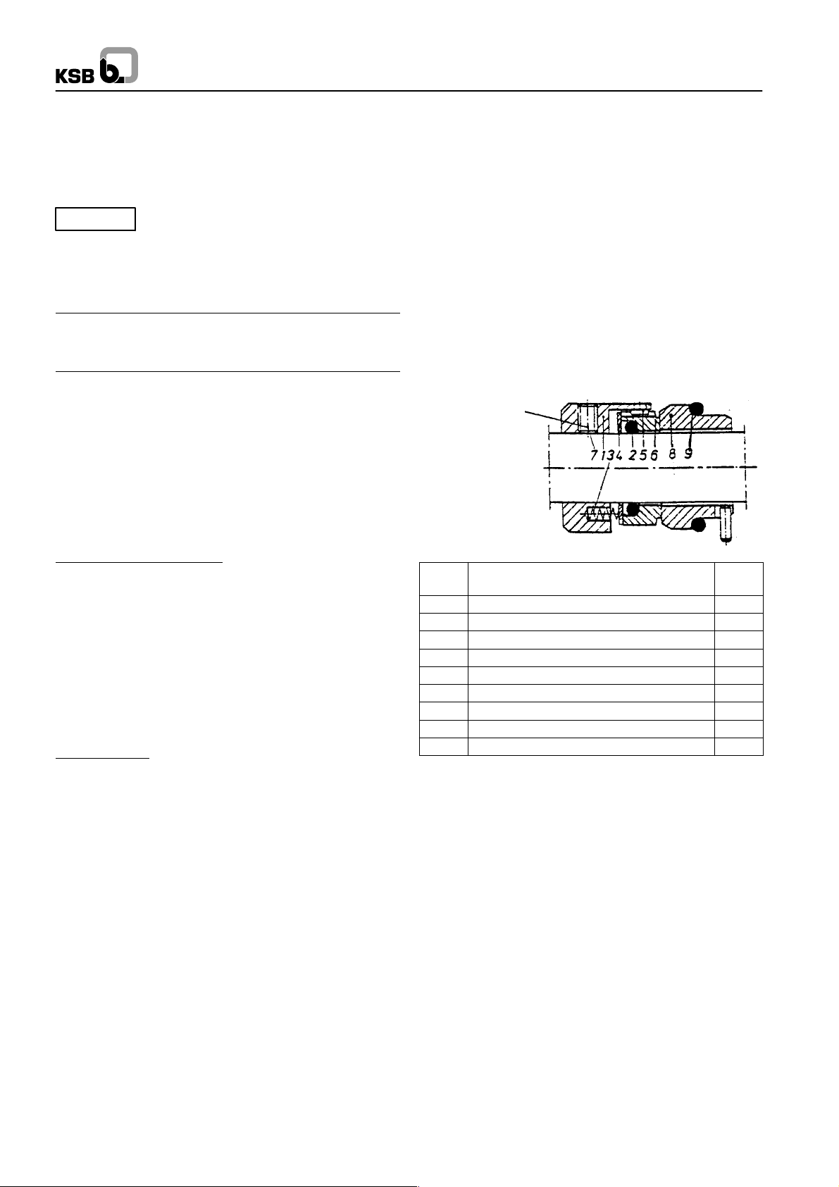
8.2.2 Mechanical Seal -- ”Type M74N ”
(Shaft unit d
This mechanical seal type is a single--acting, bi-- rotational,
non--balanced mechanical seal with multiple spring arrangement.
Caution
Special instructions for mechanical seal installation
= 90 mm)
w
It is imperative to avoid dry running of the
mechanical seal!
· Application limits
Pressure to be sealed off, p max.
Product temperature, t --40...220 °C
Sliding velocity, vg
25 bar
20 m/s
· Safety
Any work on the mechanical seal shall only be performed after the pump has stopped and pump pressure has beenreleased.
In addition to the safety instructions contained in this manual,
the general health and accident prevention regulations
shall be observed.
The seat ring (8) together with the relevant O--ring (9), is fitted
into the seal cover (see general drawing). The O--ring can be
lubricated for easy sliding movement. Special attention must
be given to ensure that pressure is applied evenly. The contact
surfaces are generally fitted dry.
In mechanical seals of the M74Ndesign, the rotating assembly
is supplied as one unit, consisting of a housing and pin ( 1 + 5),
fitted spring loaded ring (6), O--ring (2), spring (3), thrust plate
(4) and grub screws (7). The grub screws (7) must be loosened
so far as to prevent them from protruding from the housing (1)
at the inner diameter. The O--ring (2) can be slightly lubricated
to facilitate assembly.
The complete rotating assembly is pushed onto the shaft protection sleeve in compliance with the installation dimensions
which are given in the mech. seal drawing,or until it reaches the
stop on the shaft protection sleeve. Finally the grub screws are
tightened and secured with LOCTITE.
Degrease the grub
screws and insert
with a thread sealant
(e.g. Loctite). Use
new grub screws
whenever the mechanical seal has
been dismantled!
Preparations for installation
Check pump components
for:
· chamfered edges (sliding cones 2 mm/ 30_ or to DIN
24960).
· radiused transitions
· locating surfaces, surfaces for O--rings: fine finished Rz
10 (DIN 4768)
· Shaft surface in the area of the dynamically loaded joint
ring: roughness depth R
The shaft must be provided with the requisite recesses for
the housing screws of the mechanical seal.
Check pump
for:
max
5 mm.
· damage at the mating surfaces with the mechanical seal
· connecting dimensions, rectangularity and concentricity to
the shaft axis
Installation
For the installation of the total seal assembly (mechanical seal,
seal housing) see operating instructions for the pump.
The shaft protection sleevesand also the surfaces ofthe casing
are subjected to accurate finishingprocesses with regard to the
O--ring seats, in order to achieve a complete and reliable seal.
Care must be taken during installation to keep these parts absolutely clean, to avoid the surfaces from being damaged and
prevent entry of foreign particles.
Item Description Material No. of
items
1 Housing Cr-Ni-Mo-steel 1
2 O--ring Compat. elastomers 1
3 Spring Cr-Ni-Mo-steel 1
4 Thrust plate Cr-Ni-Mo-steel 1
5 Pin Cr-Ni-Mo-steel 2
6 Rotating ring Buka, Buke, Bume 1
7 Grub screw Cr-Ni-Mo-steel 2
8 Seat ring Buke, Buko, Buka 1
9 O--ring Compat. elastomers 1
· Apply a thin coat of grease to the shaft in the mechanical
seal area.
Sealing elements made of EP rubber must never come
into contact with mineral oil base lubricants (swelling,
possibly decomposition).
· Unwrap the mechanical seal and inspect for damage to the
spring--loaded ring and the seat ring, the O--rings and the
mating surfaces.
Never put the spring--loaded ring and the seat ring face
down on the contact faces without the protective wrapping.
· Thoroughly clean all components with alcohol and cellulose
tissue.
20
Omega
Installation
Never use force during mechanical seal installation.
· Slip the degreased O--ring onto the seat ring.
· Cover the contact face with a cardboard washer.
· Push the seat ring slowly and evenly into its seat.Use a spa-
cer sleeve, if necessary. Lubricate with a generous amount
of water or alcohol.
· Verify that the seat ring position is normal to the shaft axis.
· Push the rotating assembly with the degreased joint rings
onto the shaft. Thread in the degreased grub screws with
1 drop of thread sealant each (e.g. Loctite No. 243) and position the mechanical seal by tightening the grub screws.
The installation dimensions given in the drawing must be
adhered to.
· The contact faces must only be cleaned with propyl alcohol
and paper tissue (no cleaning rags or cloth). Clean carefully
to remove any smears. Do not touch the contact faces with
bare fingers afterwards.
The contact faces must not be lubricated; they must be clean
and dry.
· Assemble the seal cover with the installed seat ring.
Commissioning
Flood the pump and the seal chamber with the medium to be
handled and vent carefully. The seal is operational now.
Faults
Determine and document the nature of the fault.
In the event of a fault as evidenced by excessive leakage, observe the tendency of the leakage amount. Changes in operating conditions must be documented. If an excessive temperature rise is detected, the mechanical seal must beshut down for
safety reasons.
A continuous flow of leakage indicates a fault.
During the warranty period the mechanical s eal shall only be removed and dismantled with the manufacturer’s approval or under instructions of the mechanical seal manufacturer’s service
engineers.
If the fault cannot be remedied by the operator or if the cause
is unclear, please contact the KSB service centre.
Maintenance
Mechanical seals operated in compliance with the manual are
maintenance--free; however, wear parts will have to be replaced as required.
The mechanical seal should be inspected in accordance with
the plant inspection schedule. We recommend to have the mechanical seal inspected by KSB service centre.
If the mechanical sealis inspected during plant outage,the contact faces should be re--worked and all elastomer seals and
springs should be replaced.
Reliable seal operation
On single --acting mechanical seals, the pressure in the seal
chamber of the pump (stuffing box) must always exceed ambient pressure, to prevent any air intake at the seal faces,
which would result in dry running and thus failure of the mechanical seal.
In all operating conditions, the product to be sealed off must
be available in liquid state at the mechanical seal, particularly
during pump start--up and shutdown. This must be ensured by
appropriate facilities on the pump (e.g. heating).
If the operating conditions indicated are observed and the instructions given in this operating manual are complied with, the
mechanical seal can be expected to give trouble--free operation.
Should the mechanical seal fail, the liquid to be sealed
off may spurt out.Takesuitable precautions to pre-
vent hazards to persons and the environment, e.g. install
splash guards, wear safety goggles, etc. Proper disposal of
leakage shall be arranged for and supervised by the operator.
Repair
If the seal needs to be repaired,alwaysreturn the complete
seal to the manufacturer. The manufacturer will know best
which parts can be re--worked andwhich parts have to be replaced to ensure an optimum sealing effect.
If repair on the spot is absolutely necessary (e.g. no spare
seal available, longtransport distances,problems with customs
procedures), skilled operator staff may carry out the repair
work in a clean workshop to the directions of KSB service centres.
21
Omega
Mechanical seal removal
Shut down the pump in accordance with the operating
manual, allow to cool down and release pump pressure.
There must be no pumped product at the
mechanical seal ®The pump must be drained.
Secure the pump to prevent inadvertent start--up.
Follow the safety instructions
(safety data sheets)!
Make sure to comply with the applicable accident preven-
tion regulations when removing a mechanical seal. Also observe the instructions for handling hazardous substances
if the mechanical seal has already been in operation. If you
have any queries about the applicable regulations please in-
form yourself before commencing any repair work.
Any work on the mechanical seal is only permitted with the
pump shut down and pump pressure released.
Removal of the mechanical seal shall be performed analogously with mechanical seal installation, but in reverse order.
Removing the subassembly
See section 7.3.
· Grub screw (7) und Dichtringe (2+9) nach jederDemontage
erneuern.
8.2.3 Mechanical Seal ”Type HJ92 N”
(Shaft unit d
Note:
Refer to sections 8.2.1 and 8.2.2 for general recommendations
and instructions for handling this seal type.
For detailed information please refer to the operating manual
for seal type HJ92 N.
=40to80mm)
w
Spare parts
Only genuine spare parts shall be used. Non--compliance
with this requirement entails the risk of seal malfunctions
which may jeopardize the safety of personnel and the environment.
It will also lead to forfeiture of all warranty claims.To keep a
complete spare seal on stock.
22

OPERATING MANUAL
MECHANICAL SEAL (MS)
HJ92N
PLEASE READ this manual carefully and OBSERVE the information contained as to:
H Safety H
Storage H Installation H Start up H Maintenance H Repair
J SAFETY
Any personin the operator’s plant who is involved in the installation, removal, operation, commissioning and maintenance of
the mechanical seal must have read and thoroughly understood these operating instructions, particularly the safety instructions contained therein. It is advisable for the operator to
have this confirmed.
The mechanicalseal isa precision product (ISO 9001) and safe
to operate. However, it may constitute a hazard if it is not used
in accordance with its designated use, or if operatedimproperly
by unskilled personnel.
The operator has to determine the consequences of any mechanical seal failure and decide whether safety precautions
need to be taken to protect personnel or the environment.
The pump shall be installed in such a way that any fluidspurting
out cannot cause personal injury and that leakage can be properly disposed of.
Any operating mode liable to impair the safe and reliable function of the mechanical seal is not permitted.
Mechanical seals shall only be installed, operated, removed or
repaired by authorized, qualified and appropriately instructed
personnel.
Any work on the mechanical seal shall only be performed with
the pump shut down and the pump pressure released.
Staff responsibilities for the work involved must be clearly defined and complied with, to prevent unclear competencies with
regard to safety aspects.
In addition to the instructions contained in this manual, the general occupational health and safety regulations must be adhered to.
Unauthorized modifications and alterations liable to jeopardize
the safe operation of the mechanical seal are not permitted.
J OPERATING LIMITS
Shaft diameter dw: 18 to 100 mm
Press. to be sealed off p max.: 25 bar
Fluid temperature t: -- 40 to 220 °C
Sliding velocity vg: 20 m/s
*)
depending on the seal face materials
The mechanical seal shall not be operated at several application limits at the same time.
Higher loads (pressure, temperature, speed) may lead to increased wear and damage the contact faces or the elastomer
elements.
Such operating conditions would shorten the useful life of the
seal but also entail the risk of sudden seal failure with hazards
to personnel and the environment.
*)
J O PERAT ING DATA
The operating data for the application in question, such as fluid
to be sealed off, operating pressure, operating temperature, rotational speed, etc., are indicated on the respective pump data
sheets.
J DESIGNATED USE
Any operation outside the operating conditions stated in the
”Operating Limits” section is deemed to be non--conforming
with the designated use.
To ensure safe operation of the mechanical seal, check withthe
seal manufacturer before using the seal for other operating
conditions or in a different location of operation.
J MATERIALS
Materials as per drawing and/or order.
J DRAWINGS
General assembly drawing of pump.
The applicable design is shown on the general pump drawing
in the original scale and latest revision, see section 9 of the
pump’s operating manual, which shall be used in conjunction
with this document.
J DECLARATION
within the meaning of EC Directive ”Machinery” 98/37/EC.
A mechanical seal does not function independently. It is intended to be incorporated into or assembled with machinery.
Operating maual mechanical seal
Rev. 0, 13.02.2004
J SPECIFICATION
H Single mechanical seal
H Balanced
H Bi--rotational
H Connecting dimensions to DIN 24960 KB
H Installation dimensions l
1K
23
 Loading...