

Page 1
Waste Water, Condensate and Heat
Transfer Fluid Pump
MK
Installation/Operating Manual
Page 2

Legal information/Copyright
Installation/Operating Manual MK
Original operating manual
All rights reserved. The contents provided herein must neither be distributed, copied, reproduced,
edited or processed for any other purpose, nor otherwise transmitted, published or made available to a
third party without the manufacturer's express written consent.
Subject to technical modification without prior notice.
© KSB SE & Co. KGaA, Frankenthal 11/10/2018
Page 3

Contents
3 of 64
MK
Contents
Glossary .................................................................................................................................................. 5
1 General.................................................................................................................................................... 6
1.1 Principles ...........................................................................................................................................................6
1.2 Installation of partly completed machinery....................................................................................................6
1.3 Target group.....................................................................................................................................................6
1.4 Other applicable documents............................................................................................................................6
1.5 Symbols .............................................................................................................................................................6
1.6 Key to safety symbols/markings.......................................................................................................................7
2 Safety...................................................................................................................................................... 8
2.1 General..............................................................................................................................................................8
2.2 Intended use .....................................................................................................................................................8
2.2.1 Prevention of foreseeable misuse.......................................................................................................8
2.3 Personnel qualification and training...............................................................................................................8
2.4 Consequences and risks caused by non-compliance with this manual .........................................................9
2.5 Safety awareness ..............................................................................................................................................9
2.6 Safety information for the operator/user.......................................................................................................9
2.7 Safety information for maintenance, inspection and installation ................................................................9
2.8 Unauthorised modes of operation................................................................................................................10
2.9 Explosion protection ......................................................................................................................................10
2.9.1 Marking ..............................................................................................................................................10
2.9.2 Temperature limits.............................................................................................................................10
2.9.3 Monitoring equipment......................................................................................................................11
2.9.4 Operating limits .................................................................................................................................11
3 Transport/Temporary Storage/Disposal............................................................................................. 12
3.1 Checking the condition upon delivery..........................................................................................................12
3.2 Transport.........................................................................................................................................................12
3.3 Storage/preservation......................................................................................................................................12
3.4 Return to supplier...........................................................................................................................................13
3.5 Disposal ...........................................................................................................................................................14
4 Description of the Pump (Set)............................................................................................................. 15
4.1 General description ........................................................................................................................................15
4.2 Designation.....................................................................................................................................................15
4.3 Name plate......................................................................................................................................................15
4.4 Design details..................................................................................................................................................16
4.5 Configuration and function...........................................................................................................................17
4.6 Noise characteristics .......................................................................................................................................19
4.7 Scope of supply...............................................................................................................................................19
5 Installation at Site................................................................................................................................ 20
5.1 Safety regulations...........................................................................................................................................20
5.2 Checks to be carried out prior to installation...............................................................................................20
5.3 Fitting and setting the float switch control (optional) ................................................................................20
5.3.1 Control elements for MK/MKA .........................................................................................................20
5.3.2 Control element for MKY..................................................................................................................23
5.4 Installing the pump set ..................................................................................................................................23
5.5 Connecting the piping ...................................................................................................................................23
5.6 Permissible forces and moments at the pump nozzles ................................................................................24
5.7 Electrical connection ......................................................................................................................................24
5.8 Checking the direction of rotation................................................................................................................25
6 Commissioning/Start-up/Shutdown................................................................................................... 27
6.1 Commissioning/Start-up.................................................................................................................................27
6.1.1 Prerequisites for commissioning/start-up .........................................................................................27
Page 4

Contents
4 of 64
MK
6.1.2 Filling in lubricants.............................................................................................................................27
6.1.3 Start-up...............................................................................................................................................27
6.1.4 Shutdown ...........................................................................................................................................28
6.2 Operating limits..............................................................................................................................................29
6.2.1 Ambient temperature........................................................................................................................29
6.2.2 Frequency of starts.............................................................................................................................29
6.2.3 Fluid handled .....................................................................................................................................30
6.3 Shutdown/storage/preservation ....................................................................................................................31
6.3.1 Measures to be taken for shutdown ................................................................................................31
6.4 Returning to service .......................................................................................................................................32
7 Servicing/Maintenance........................................................................................................................ 33
7.1 Safety regulations...........................................................................................................................................33
7.2 Servicing/Inspection........................................................................................................................................34
7.2.1 Supervision of operation...................................................................................................................34
7.2.2 Lubrication and lubricant change.....................................................................................................35
7.3 Drainage/cleaning ..........................................................................................................................................39
7.4 Dismantling the pump set..............................................................................................................................40
7.4.1 General information/Safety regulations...........................................................................................40
7.4.2 Removing the pump set from the piping.........................................................................................40
7.4.3 Dismantling the pump section ..........................................................................................................41
7.5 Reassembling the pump set...........................................................................................................................43
7.5.1 General information/Safety regulations...........................................................................................43
7.5.2 Reassembling the pump section .......................................................................................................44
7.6 Tightening torques.........................................................................................................................................48
7.7 Spare parts stock.............................................................................................................................................48
7.7.1 Ordering spare parts..........................................................................................................................48
7.7.2 Recommended spare parts stock for 2 years' operation to DIN24296 ..........................................48
8 Trouble-shooting.................................................................................................................................. 50
9 Related Documents.............................................................................................................................. 52
9.1 General assembly drawings/exploded views with list of components........................................................52
9.1.1 MK, MKA ............................................................................................................................................52
9.1.2 MK, MKA - grease-lubricated............................................................................................................53
9.1.3 MK, MKA - internally lubricated by fluid handled ..........................................................................54
9.1.4 MK, MKA - lubricated by an external fluid ......................................................................................55
9.1.5 MKY ....................................................................................................................................................57
10 EU Declaration of Conformity............................................................................................................. 59
11 Certificate of Decontamination........................................................................................................... 60
Index ..................................................................................................................................................... 61
Page 5

Glossary
5 of 64
MK
Glossary
Certificate of decontamination
A certificate of decontamination is enclosed by the
customer when returning the product to the
manufacturer to certify that the product has been
properly drained to eliminate any environmental
and health hazards arising from components in
contact with the fluid handled.
Discharge line
The pipeline which is connected to the discharge
nozzle
Pump
Machine without drive, additional components or
accessories
Pump set
Complete pump set consisting of pump, drive,
additional components and accessories
Page 6
1 General
6 of 64
MK
1 General
1.1 Principles
This operating manual is supplied as an integral part of the type series and variants
indicated on the front cover.
The manual describes the proper and safe use of this equipment in all phases of
operation.
The name plate indicates the type series and size, the main operating data, the order
number and the order item number. The order number and order item number
clearly identify the pump set and serve as identification for all further business
processes.
In the event of damage, immediately contact your nearest KSB Service centre to
maintain the right to claim under warranty.
1.2 Installation of partly completed machinery
To install partly completed machinery supplied by KSB refer to the sub-sections under
Servicing/Maintenance.
1.3 Target group
This operating manual is aimed at the target group of trained and qualified specialist
technical personnel. (ðSection2.3,Page8)
1.4 Other applicable documents
Table1: Overview of other applicable documents
Document Contents
Data sheet Description of the technical data of the pump (set)
General arrangement drawing/
outline drawing
Description of mating and installation dimensions
for the pump (set), weights
Hydraulic characteristic curve Characteristic curves showing head, NPSH
required
,
efficiency and power input
General assembly drawing
1)
Sectional drawing of the pump
Sub-supplier product literature1)Operating manuals and other product literature
describing accessories and integrated machinery
components
Spare parts lists
1)
Description of spare parts
Piping layout
1)
Description of auxiliary piping
List of components
1)
Description of all pump components
For accessories and/or integrated machinery components, observe the relevant
manufacturer's product literature.
1.5 Symbols
Table2: Symbols used in this manual
Symbol Description
✓ Conditions which need to be fulfilled before proceeding with the
step-by-step instructions
⊳ Safety instructions
⇨
Result of an action
⇨ Cross-references
1) If agreed to be included in the scope of supply
Page 7
1 General
7 of 64
MK
Symbol Description
1.
2.
Step-by-step instructions
Note
Recommendations and important information on how to handle
the product
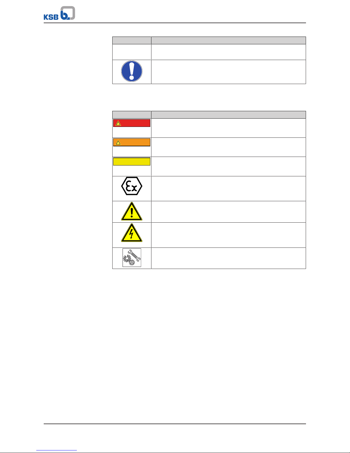
1.6 Key to safety symbols/markings
Table3: Definition of safety symbols/markings
Symbol Description
!
DANGER
DANGER
This signal word indicates a high-risk hazard which, if not avoided,
will result in death or serious injury.
!
WARNING
WARNING
This signal word indicates a medium-risk hazard which, if not
avoided, could result in death or serious injury.
CAUTION
CAUTION
This signal word indicates a hazard which, if not avoided, could
result in damage to the machine and its functions.
Explosion protection
This symbol identifies information about avoiding explosions in
potentially explosive atmospheres in accordance with EU Directive
2014/34/EU (ATEX).
General hazard
In conjunction with one of the signal words this symbol indicates a
hazard which will or could result in death or serious injury.
Electrical hazard
In conjunction with one of the signal words this symbol indicates a
hazard involving electrical voltage and identifies information about
protection against electrical voltage.
Machine damage
In conjunction with the signal word CAUTION this symbol indicates
a hazard for the machine and its functions.
Page 8

2 Safety
8 of 64
MK
2 Safety
!
DANGER
All the information contained in this section refers to hazardous situations.
In addition to the present general safety information the action-related safety
information given in the other sections must be observed.
2.1 General
This operating manual contains general installation, operating and maintenance
instructions that must be observed to ensure safe operation of the system and
prevent personal injury and damage to property.
The safety information in all sections of this manual must be complied with.
The operating manual must be read and understood by the responsible specialist
personnel/operators prior to installation and commissioning.
The contents of this operating manual must be available to the specialist personnel
at the site at all times.
Information attached directly to the product must always be complied with and kept
in a perfectly legible condition at all times. This applies to, for example:
▪ Arrow indicating the direction of rotation
▪ Markings for connections
▪ Name plate
The operator is responsible for ensuring compliance with all local regulations not
taken into account in this operating manual.
2.2 Intended use
▪ The pump (set) must only be operated in the fields of application and within the
use limits specified in the other applicable documents.
▪ Only operate pumps/pump sets which are in perfect technical condition.
▪ Do not operate the pump (set) in partially assembled condition.
▪ Only use the pump to handle the fluids described in the data sheet or product
literature of the pump model or variant.
▪ Never operate the pump without the fluid to be handled.
▪ Observe the minimum flow rates indicated in the data sheet or product literature
(to prevent overheating, bearing damage, etc).
▪ Observe the minimum flow rate and maximum flow rate indicated in the data
sheet or product literature (to prevent overheating, mechanical seal damage,
cavitation damage, bearing damage, etc).
▪ Do not throttle the flow rate on the suction side of the pump (to prevent
cavitation damage).
▪ Consult the manufacturer about any use or mode of operation not described in
the data sheet or product literature.
2.2.1 Prevention of foreseeable misuse
▪ Never open the discharge-side shut-off elements further than permitted.
– The maximum flow rates specified in the product literature or data sheet
would be exceeded.
– Risk of cavitation damage
▪ Never exceed the permissible application and operating limits specified in the
data sheet or product literature regarding pressure, temperature, etc.
▪ Observe all safety information and instructions in this manual.
2.3 Personnel qualification and training
All personnel involved must be fully qualified to transport, install, operate, maintain
and inspect the machinery this manual refers to.
Page 9

2 Safety
9 of 64
MK
The responsibilities, competence and supervision of all personnel involved in
transport, installation, operation, maintenance and inspection must be clearly
defined by the operator.
Deficits in knowledge must be rectified by means of training and instruction
provided by sufficiently trained specialist personnel. If required, the operator can
commission the manufacturer/supplier to train the personnel.
Training on the pump (set) must always be supervised by technical specialist
personnel.
2.4 Consequences and risks caused by non-compliance with this manual
▪ Non-compliance with these operating instructions will lead to forfeiture of
warranty cover and of any and all rights to claims for damages.
▪ Non-compliance can, for example, have the following consequences:
– Hazards to persons due to electrical, thermal, mechanical and chemical
effects and explosions
– Failure of important product functions
– Failure of prescribed maintenance and servicing practices
– Hazard to the environment due to leakage of hazardous substances
2.5 Safety awareness
In addition to the safety information contained in this manual and the intended use,
the following safety regulations shall be complied with:
▪ Accident prevention, health regulations and safety regulations
▪ Explosion protection regulations
▪ Safety regulations for handling hazardous substances
▪ Applicable standards, directives and laws
2.6 Safety information for the operator/user
▪ Fit protective equipment (e.g. contact guards) supplied by the operator for hot,
cold or moving parts, and check that the equipment functions properly.
▪ Do not remove any protective equipment (e.g. contact guards) during operation.
▪ Provide the personnel with protective equipment and make sure it is used.
▪ Contain leakages (e.g. at the shaft seal) of hazardous fluids handled (e.g.
explosive, toxic, hot) so as to avoid any danger to persons and the environment.
Adhere to all relevant laws.
▪ Eliminate all electrical hazards. (In this respect refer to the applicable national
safety regulations and/or regulations issued by the local energy supply
companies.)
▪ If shutting down the pump does not increase potential risk, fit an emergency-
stop control device in the immediate vicinity of the pump (set) during pump set
installation.
2.7 Safety information for maintenance, inspection and installation
▪ Modifications or alterations of the pump (set) are only permitted with the
manufacturer's prior consent.
▪ Use only original spare parts or parts/components authorised by the
manufacturer. The use of other parts/components can invalidate any liability of
the manufacturer for resulting damage.
▪ The operator ensures that maintenance, inspection and installation is performed
by authorised, qualified specialist personnel who are thoroughly familiar with
the manual.
▪ Only carry out work on the pump (set) during standstill of the pump.
Page 10
2 Safety
10 of 64
MK
▪ Only perform work on the pump set when it has been disconnected from the
power supply (de-energised).
▪ The pump (set) must have cooled down to ambient temperature.
▪ Pump pressure must have been released and the pump must have been drained.
▪ When taking the pump set out of service always adhere to the procedure
described in the manual. (ðSection6.3,Page31)
▪ Decontaminate pumps which handle fluids posing a health hazard.
▪ As soon as the work has been completed, re-install and re-activate any safety-
relevant devices and protective devices. Before returning the product to service,
observe all instructions on commissioning. (ðSection6.1,Page27)
2.8 Unauthorised modes of operation
Never operate the pump (set) outside the limits stated in the data sheet and in this
manual.
The warranty relating to the operating reliability and safety of the supplied pump
(set) is only valid if the equipment is used in accordance with its intended use.
(ðSection2.2,Page8)
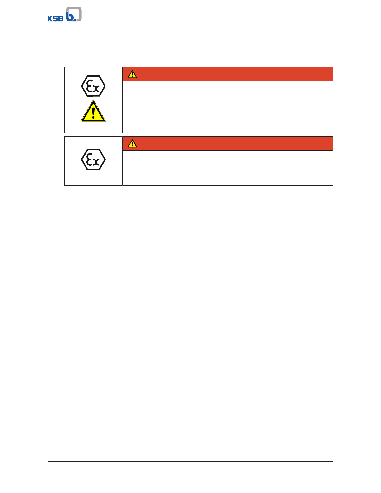
2.9 Explosion protection
!
DANGER
Always observe the information on explosion protection given in this section when
operating the product in potentially explosive atmospheres.
Only pumps/pump sets marked as explosion-proof and identified as such in the data
sheet may be used in potentially explosive atmospheres.
Special conditions apply to the operation of explosion-proof pump sets to EU
Directive 2014/34/EU (ATEX).
Especially adhere to the sections in this manual marked with the symbol opposite and
the following sections, (ðSection2.9.1,Page10) to (ðSection2.9.4,Page11)
The explosion-proof status of the pump set is only assured if the pump set is used in
accordance with its intended use.
Never operate the pump set outside the limits stated in the data sheet and on the
name plate.
Prevent impermissible modes of operation at all times.
2.9.1 Marking
Pump The marking on the pump refers to the pump part only.
Example of such marking:
II 2 G c TX (EN 13463-1) or II 2G Ex h IIC T5-T1 Gb (ISO 80079-36)
The pump complies with the requirements of type of protection constructional safety
"c" to ISO80079-37.
Refer to the data sheet for the applicable temperature class.
Motor The motor has its own marking. The marking is maintained on the condition that the
temperatures the pump causes to develop at the motor flange and motor shaft are
permitted by the motor manufacturer.
The motors used by KSB on pumps with ATEX certification meet this condition.
2.9.2 Temperature limits
In normal pump operation, the highest temperatures are to be expected at the
surface of the pump casing, the pipe assembly, the plain bearings and in the bearing
areas.
The surface temperature at the pump casing corresponds to the temperature of the
fluid handled. If the pump is heated in addition, the operator of the system is
responsible for observing the specified temperature class and fluid temperature
(operating temperature).
The table below lists the temperature classes and the resulting theoretical
temperature limits of the fluid handled (a potential temperature rise in the shaft seal
area has been taken into account).
Page 11
2 Safety
11 of 64
MK
The temperature class specifies the maximum permissible temperature at the surface
of the pump set during operation. For the permissible operating temperature of the
pump in question refer to the data sheet.
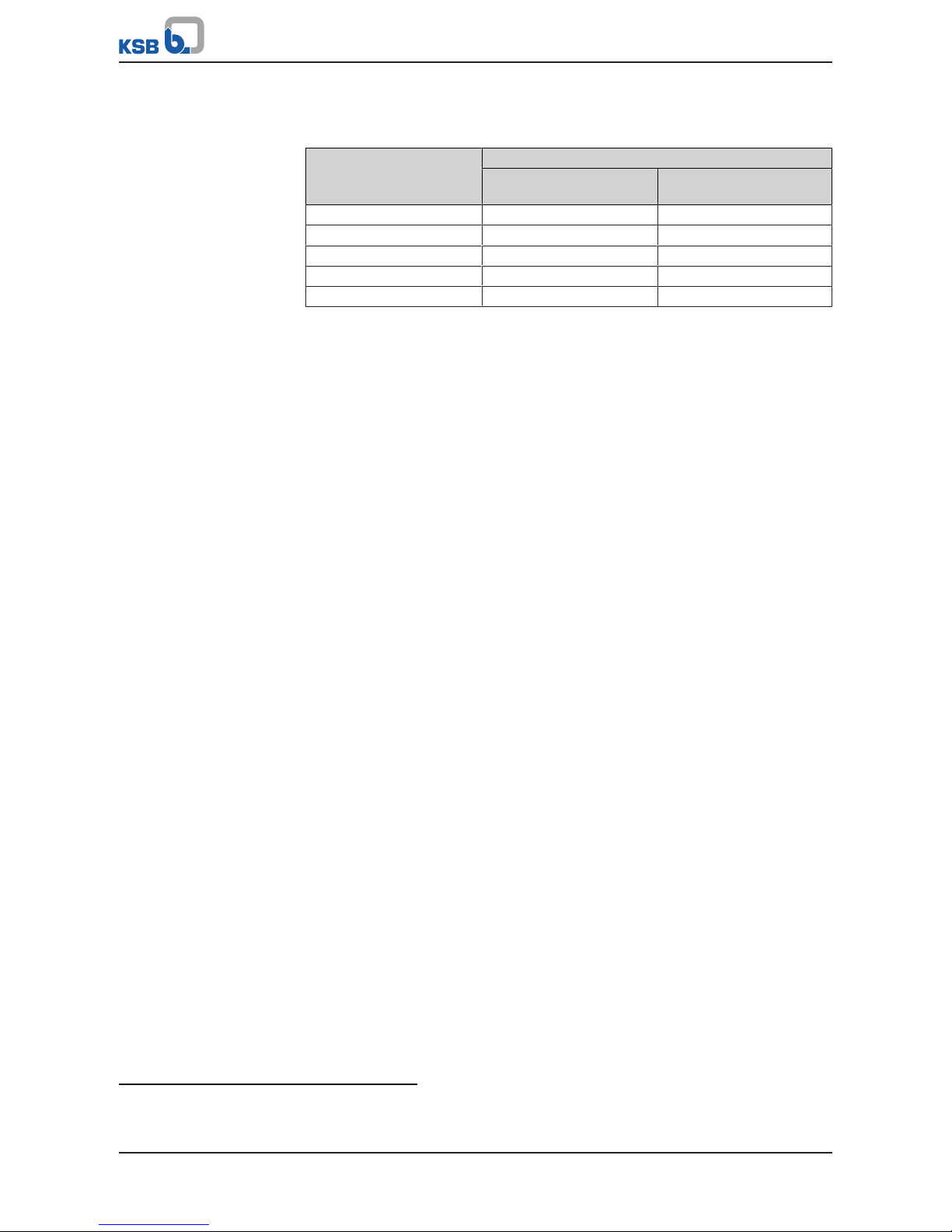
Table4: Temperature limits
Temperature class to EN 13463-1 or ISO
80079-36
Maximum permissible fluid temperature
T1 90°C
T2 90°C
T3 90°C
T4 90°C
T5 80°C
Temperature class T5 Temperature class T5 can only be complied with if the bearing temperature is limited
to 80°C.
Misuse, malfunctions or non-compliance with the instructions may result in
substantially higher temperatures.
If the pump is to be operated at a higher temperature, if there is no data sheet or if
the pump is part of a pool of pumps, contact KSB for the maximum permissible
operating temperature.
2.9.3 Monitoring equipment
The pump (set) must only be operated within the limits specified in the data sheet
and on the name plate.
If the system operator cannot warrant compliance with these operating limits,
appropriate monitoring devices must be used.
Check whether monitoring equipment is required to ensure that the pump set
functions properly.
Contact KSB for further information on monitoring equipment.
Bearing temperature monitoring
If temperature class T5 is to be complied with, the bearing temperature must be
monitored. For this purpose, the pump must be equipped with a temperature sensor
at the drive-end fixed bearing (G 1/8 connection, DIN 3852).
The temperature sensor must be operated with an ATEX-approved transducer
providing explosion protection for the sensor. The bearing temperature must be
monitored so as to ensure it does not exceed 80°C.
2.9.4 Operating limits
The minimum flows indicated in (ðSection6.2.3.1,Page30) refer to water and
water-like fluids handled. Longer operating periods with these fluids and at the flow
rates indicated will not cause an additional increase in the temperatures at the pump
surface. However, if the physical properties of the fluids handled are different from
water, it is essential to check whether an additional heat build-up may occur and if
the minimum flow rate must therefore be increased. The calculation formula in
(ðSection6.2.3.1,Page30) can be used to check whether additional heat build-up
may lead to a dangerous temperature increase at the pump surface.
Page 12
3 Transport/Temporary Storage/Disposal
12 of 64
MK
3 Transport/Temporary Storage/Disposal
3.1 Checking the condition upon delivery
1. On transfer of goods, check each packaging unit for damage.
2. In the event of in-transit damage, assess the exact damage, document it and
notify KSB or the supplying dealer and the insurer about the damage in writing
immediately.
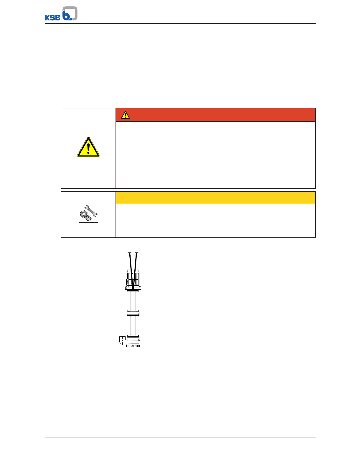
3.2 Transport
DANGER
The pump (set) could slip out of the suspension arrangement
Danger to life from falling parts!
▷ Always transport the pump (set) in the specified position.
▷ Never attach the suspension arrangement to the free shaft end or the motor
eyebolt.
▷ Observe the information about weights, centre of gravity and fastening points.
▷ Observe the applicable local accident prevention regulations.
▷ Use suitable, permitted lifting accessories, e.g. self-tightening lifting tongs.
CAUTION
Incorrect transport of the pump
Damage to the shaft seal!
▷ For transport, lock the pump shaft with a suitable transport lock to prevent any
movement of the shaft.
To transport the pump/pump set suspend it from the lifting tackle as shown.
Fig.1: Transporting the complete pump set
3.3 Storage/preservation
If commissioning is to take place some time after delivery, we recommend that the
following measures be taken for pump (set) storage.
Page 13
3 Transport/Temporary Storage/Disposal
13 of 64
MK
CAUTION
Damage during storage due to humidity, dirt or vermin
Corrosion/contamination of the pump (set)!
▷ For outdoor storage cover the pump (set) or the packaged pump (set) and
accessories with waterproof material.
CAUTION
Wet, contaminated or damaged openings and connections
Leakage or damage to the pump!
▷ Clean and cover pump openings and connections as required prior to putting
the pump into storage.
Store the pump (set) in a dry, protected room where the atmospheric humidity is as
constant as possible.
Rotate the shaft by hand once a month, e.g. via the pump impeller.
If properly stored indoors, the equipment is protected for a maximum of 12 months.
New pumps/pump sets are supplied by our factory duly prepared for storage.
For storing a pump (set) which has already been operated, observe the instructions in
(ðSection6.3.1,Page31) .
3.4 Return to supplier
1. Drain the pump as per operating instructions. (ðSection7.3,Page39)
2. Flush and clean the pump, particularly if it has been used for handling noxious,
explosive, hot or other hazardous fluids.
3. If the pump has handled fluids whose residues could lead to corrosion damage
in the presence of atmospheric humidity or could ignite upon contact with
oxygen also neutralise the pump and blow through with anhydrous inert gas to
ensure drying.
4. Always complete and enclose a certificate of decontamination when returning
the pump.
Indicate any safety measures and decontamination measures taken.
(ðSection11,Page60)
NOTE
If required, a blank certificate of decontamination can be downloaded from the
following web site: www.ksb.com/certificate_of_decontamination
Page 14

3 Transport/Temporary Storage/Disposal
14 of 64
MK
3.5 Disposal
WARNING
Fluids handled, consumables and supplies which are hot and/or pose a health
hazard
Hazard to persons and the environment!
▷ Collect and properly dispose of flushing fluid and any fluid residues.
▷ Wear safety clothing and a protective mask if required.
▷ Observe all legal regulations on the disposal of fluids posing a health hazard.
1. Dismantle the pump (set).
Collect greases and other lubricants during dismantling.
2. Separate and sort the pump materials, e.g. by:
- Metals
- Plastics
- Electronic waste
- Greases and other lubricants
3. Dispose of materials in accordance with local regulations or in another
controlled manner.
Page 15
4 Description of the Pump (Set)
15 of 64
MK
4 Description of the Pump (Set)
4.1 General description
▪ Waste water, condensate and heat transfer fluid pump
Pump for handling waste water, oils, emulsions, condensate, heat transfer fluids and
aggressive fluids.
4.2 Designation
MK A - B 20 - 1/ 100
Table5: Designation key
Code Description
MK Type series
A Design
-
2)
Pump without discharge pipe, without cover plate, with motor
A Pump with square mounting/cover plate and discharge pipe, with
motor
Y Pump with round mounting/cover plate and flanged discharge
pipe, with lantern, gland packing and motor
B Casing material
Grey cast iron
B Tin bronze
C Chrome nickel molybdenum cast steel
2 Pipe connection
2 Rp 2
0 Design status
1 Power code (defines the impeller diameter)
1 - 6
100 Installation depth [cm]
100, 190, 280
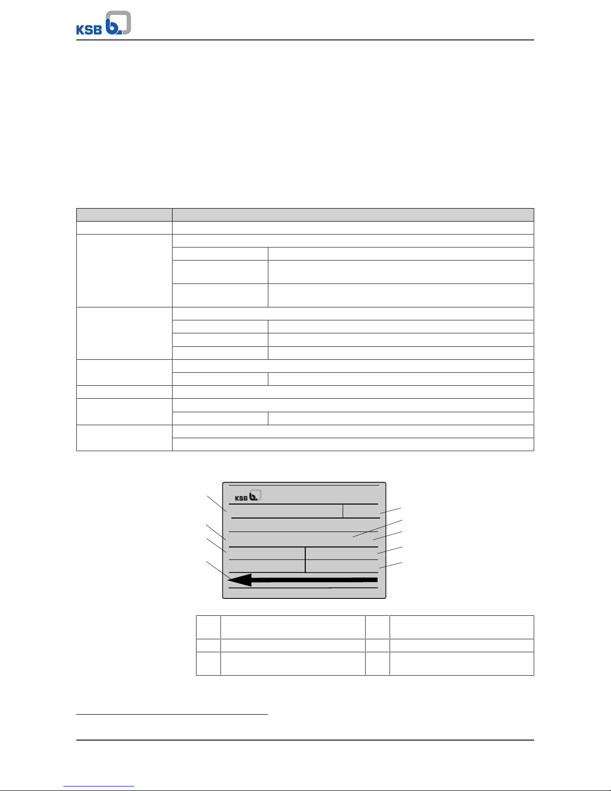
4.3 Name plate
No. 9971402925/ 000200 / 01
Q 10 m3/h H 3 m
n 1450 1/min
Ident.-No. 00 391 209 AN 886-82
2016
MKA-B 20-1/100
1
2
6
5
3
9
8
7
4
Johann-Klein-Straße 9
Deutschland
67227 Frankenthal
KSB SE & Co. KGaA
Fig.2: MK name plate (example)
1 Type series, size and version 2 KSB order number
(ten digits)
3 Flow rate 4 Direction of rotation
5 Year of construction 6 Order item number
(six digits)
2) Blank
Page 16

4 Description of the Pump (Set)
16 of 64
MK
7 Consecutive number
(two digits)
8 Head
9 Speed
4.4 Design details
Design
▪ Volute casing
▪ Vertical installation
▪ Rigid connection between pump and motor
▪ Single-stage
Drive
▪ KSB surface-cooled IEC three-phase current squirrel-cage motor
▪ 230/400V
▪ Type of construction V1
▪ Enclosure IP55
▪ Motors integrated in explosion-proof pump sets are supplied in Ex eb IIB / Ex db
eb IIC type of protection.
Shaft seal
MK, MKA:
▪ Vapour barrier
MKY:
▪ Gland packing
Impeller type
▪ Three-channel impeller
Bearings
Drive end:
▪ Radial ball bearing
▪ Greased for life
Impeller end:
▪ Bearing bush
▪ Product-lubricated
▪ Optional:
– Internal lubrication by fluid handled
– Grease lubrication
– Lubrication by external fluid
Explosion protection
MK, MKA:
▪ Available
▪ For explosion-proof variants one of the optional lubrication types must be used
for the bearing bush.
MKY:
▪ Not available
Page 17

4 Description of the Pump (Set)
17 of 64
MK
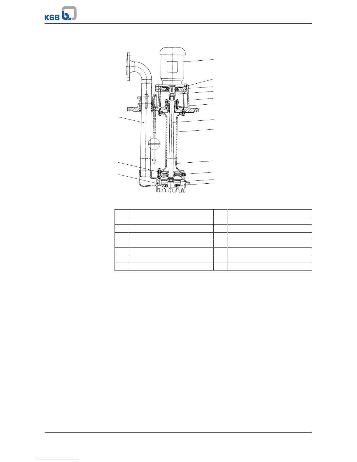
4.5 Configuration and function
MKA
8
9
11
10
12
13
14
15
1
2
3
4
5
6
7
Fig.3: MK, MKA
1 Thrust and radial bearing 2 Radial ball bearing
3 Shaft 4 Support column
5 Discharge pipe 6 Bearing bush
7 Volute casing 8 Motor
9 Cover plate 10 Shaft coupling
11 Vapour barrier 12 Overflow opening
13 Radial bearing 14 Impeller
15 Clearance gap
Design The vertical non-self-priming submerged pump in single-stage, single-entry design
features an axial fluid inlet and a radial fluid outlet.
At the drive end the rotor is axially and radially supported by a radial ball bearing
which is greased for life; at the impeller end it is radially supported by a productlubricated bearing bush. It is connected to the motor by a rigid coupling sleeve.
Various installation depths can be accommodated by up to three support column sets
and matching incremental lengths of the shaft assembly. The required radial bearings
are lubricated by the fluid handled. As an alternative, external lubrication can be
used. To protect the drive-end radial ball bearing the shaft is enclosed by a vapour
barrier below the thrust and radial bearing. For pump sets installed with a cover
plate (MKA) the discharge nozzle of the volute casing is connected to the plate via a
discharge pipe.
Function The uniformly rotating impeller of the submerged pump transfers mechanical energy
to the fluid passing through. The fluid enters the pump set vertically via the suction
nozzle and is accelerated outward by the rotating impeller. In the flow passage of
the volute casing the kinetic energy of the fluid handled is converted into pressure
energy. The fluid leaves the pump set via the discharge nozzle. The clearance gap
minimises the fluid flowing back from the volute casing into the suction nozzle. On
the rear side of the impeller, the hydraulic system extends up to the radial bearing
with bearing bush. The shaft passes through the radial bearing.
Sealing Apart from a vapour barrier protecting the fixed bearing the pump set is seal-less. A
small amount of leakage flows into the support column at the shaft passage and
then through the overflow opening back into the tank.
Page 18
4 Description of the Pump (Set)
18 of 64
MK
MKY
1
2
3
4
5
6
7
8
9
10
11
12
13
14
15
Fig.4: MKY
1 Discharge pipe 2 Bearing bush
3 Volute casing 4 Motor
5 Radial ball bearing 6 Thrust and radial bearing
7 Shaft coupling 8 Drive lantern
9 Shaft seal 10 Shaft
11 Support column 12 Overflow opening
13 Radial bearing 14 Impeller
15 Clearance gap
Design The vertical non-self-priming submerged pump in single-stage, single-entry design
features an axial fluid inlet and a radial fluid outlet.
Above the drive lantern the rotor is axially and radially supported by a radial ball
bearing which is greased for life; at the impeller end, it is radially supported by a
product-lubricated bearing bush. It is connected to the motor by a rigid coupling
sleeve. Various installation depths can be accommodated by up to three support
column sets and matching incremental lengths of the shaft assembly. The pump set is
installed in a drive lantern. The discharge nozzle of the volute casing is connected to
the lantern via a discharge pipe. The discharge pipe ends in a flanged bend.
Function The uniformly rotating impeller of the submerged pump transfers mechanical energy
to the fluid passing through. The fluid enters the pump vertically via the suction
nozzle and is accelerated outward by the rotating impeller. In the flow passage of
the volute casing the kinetic energy of the fluid handled is converted into pressure
energy. The fluid leaves the pump via the discharge nozzle. The clearance gap
minimises the fluid flowing back from the volute casing into the suction nozzle. On
the rear side of the impeller, the hydraulic system extends up to the radial bearing
with bearing bush. The shaft passes through the radial bearing.
Sealing The pump set is sealed towards the fixed bearing with a shaft seal (gland packing).
Page 19
4 Description of the Pump (Set)
19 of 64
MK
4.6 Noise characteristics
Table6: Surface sound pressure level L
pA
3)
Rated power input
PN [kW]
Pump set
1450 rpm
[dB]
2900 rpm
[dB]
0,55 52 0,75 57 64
1,1 - 64
1,5 - 65
2,2 - 66
4.7 Scope of supply
Depending on the model, the following items are included in the scope of supply:
▪ Pump
Drive
▪ Surface-cooled IEC frame three-phase squirrel-cage motor
Special accessories
▪ As required
Soleplate
MK:
▪ Without baseplate
MKA:
▪ Baseplate accommodating pump and motor
MKY:
▪ Baseplate integrally cast with the lantern
Monitoring equipment (optional)
▪ Temperature sensor at the drive-end fixed bearing with G 1/8 threaded
connection
Level control system (optional)
▪ Level control system with rod-actuated float switch
▪ Level control system with magnetic float switch
▪ Level control system with EURO float switch
3) Spatial average; as per ISO 3744; valid for pump operation in the Q/Qopt = 0.80 - 1.1 range and for non-cavitating
operation. If noise levels are to be guaranteed: add +3dB for measuring and constructional tolerance; the above values
apply to the pump set without cover plate. If a cover plate is fitted, this value may increase by up to 2 pA (dB).
Page 20
5 Installation at Site
20 of 64
MK
5 Installation at Site
5.1 Safety regulations
DANGER
Improper installation in potentially explosive atmospheres
Explosion hazard!
Damage to the pump set!
▷ Comply with the applicable local explosion protection regulations.
▷ Observe the information in the data sheet and on the name plates of pump and
motor.
DANGER
Improper cleaning of coated pump surfaces
Explosion hazard by electrostatic discharge!
▷ When cleaning coated pump surfaces in atmospheres of Explosion groupIIC,
use suitable anti-static equipment.
5.2 Checks to be carried out prior to installation
Check the structural requirements.
The structural work required must have been prepared in accordance with the
dimensions stated in the outline drawing and/or general arrangement drawing.
5.3 Fitting and setting the float switch control (optional)
5.3.1 Control elements for MK/MKA
5.3.1.1 Rod-actuated float switch control
The pump set is controlled by a switch fitted on the motor flange. The switch is
actuated by a float via a switch rod with stop clamps.
Page 21

5 Installation at Site
21 of 64
MK
Fitting the rod-actuated float switch
74-4
574
901.52
930.52
575.52
500.50
930.52
920.52
81-45
900.51
550.51
570
900.50
920.50
733.51
481
733.52
68-3
550.51
920.51
575.51
902.12
920.12
710.01
920.11
550.11
400.11
Fig.5: Fitting the rod-actuated float switch
a) b) c)
A A B B C C
Fig.6: Positioning the rod-actuated float switch for installation depth: a) 1000mm; b) 1900mm; c) 2800mm
A 1000 mm B 1900 mm
C 2800 mm
Page 22

5 Installation at Site
22 of 64
MK
Fig.7: Float switch a) installation position; b) switching position
1. Fasten strip 575.51 to the motor flange and strip 575.52 to the pump casing with
hexagon head bolt 901.52, hexagon nut 920.52 and spring washers 930.52.
2. Mount float switch 81-45 on strip 575.51 using hexagon socket head cap screws
900.51, discs 550.51 and nuts 920.51.
3. Fit the lever on float switch 81-45.
4. Assemble guide rod 574 with float 74-4 and the two upper adjusting rings
500.50.
5. Run the guide rod through strip 575.52 and fit adjusting ring 500.50 beneath
the strip.
6. Connect the lever and the guide rod using hexagon socket head cap screw
900.50 and hexagon nut 920.50.
7. If applicable, fit bellows 481 and hose clamp 733.51 on the guide rod.
8. Fasten the bellows on cover plate 68-3 with hose clamp 733.52.
9. Position adjusting rings 500.50 in the desired switching levels above and below
the float, respectively, to start and stop the pump as required.
10. Adjust the switching mechanism of float switch 81-45 such that the lever is
angled 42° off the horizontal in non-actuated position, see illustration of float
switch a) installation position. In installed condition, the lever position must be
as shown in the illustration of the float switch b) switching position.
ð As the float rises, the lever is lifted into the position shown and contact 15-16
closes.
11. Check that the rod-actuated float switch functions properly.
5.3.1.2 Magnetic float switch control (non-ATEX applications only)
Pump sets for installation depths of 1000 and 1900mm are controlled by a magnetic
float switch arrangement. It is equipped with a sensor tube with integrated dry-reed
contacts. The float with integrated permanent magnets can move freely along the
sensor tube and activates the dry-reed contacts when it reaches the minimum and
maximum fluid levels. The fluid levels are permanently pre-set by means of adjusting
rings.
Fitting the magnetic float switch control
1. Remove the plug from the G3/4 through-hole in the cover plate.
2. Tightly screw the magnetic float switch arrangement into the G3/4 hole provided.
Page 23

5 Installation at Site
23 of 64
MK
NOTE
The switching points - measured from the cover plate - are located at 300mm for
"ON" and 800mm (for installation depth 1000mm) or 1700mm (for installation
depth 1900mm) for "OFF" and cannot be altered. The max. contact rating is 1 A;
for MK pumps separately at the tank.
5.3.1.3 EURO float switch control (non-ATEX applications only)
The pump set is started/stopped by the float switch in response to the fluid level.
The free length of the float's connection cable (= length from the attachment point
to the float switch) defines the fluid levels for starting/stopping the pump.
Float switches with 5, 10 or 20 m connection cable must only be used for fluids with a
maximum temperature of 70 °C.
5.3.2 Control element for MKY
Pump sets installed in heat transfer fluid and recirculating systems usually do not
need any control elements.
If the pump set is used for handling condensate at temperatures of up to 110°C and
is installed at installation depths of 1000mm or 1900mm, it can be equipped with
magnetic float switch control. (ðSection5.3.1.2,Page22)
5.4 Installing the pump set
ü The installed motor is protected against flooding.
ü Motor and (optional) float switch are located outside the pit or tank.
ü Motor and (optional) float switch are ventilated and protected against moisture.
1. Remove the transport plugs from the volute casing and the discharge pipe.
2. For pump sets with installation depths of 1900mm and 2800mm without cover
plate (MK) fit the pipe union 731, which is supplied separately strapped to the
pump. (ðSection9.1.2,Page53) (ðSection9.1.4,Page55)
3. Place the pump set on the floor of a pit (approximately 500x500mm) or, if the
pump set is installed in a tank, fit it to the tank edge with a cover plate.
4. If the pump set is installed in a pit without a cover plate and angular frame,
secure it to the pit wall using mounting clamps.
5.5 Connecting the piping
DANGER
Impermissible loads acting on the pump nozzles
Danger to life from leakage of hot, toxic, corrosive or flammable fluids!
▷ Do not use the pump as an anchorage point for the piping.
▷ Anchor the pipes in close proximity to the pump and connect them properly
without transmitting any stresses or strains.
▷ Take appropriate measures to compensate for thermal expansion of the piping.
CAUTION
Incorrect earthing during welding work on the piping
Destruction of rolling element bearings (pitting effect)!
▷ Never earth the electric welding equipment on the pump or soleplate.
▷ Prevent current flowing through the rolling element bearings.
Page 24

5 Installation at Site
24 of 64
MK
NOTE
Installing check and shut-off elements in the system is recommended, depending on
the type of plant and pump. However, such elements must not obstruct proper
drainage or hinder disassembly of the pump.
NOTE
If the pump is used for automatic drainage, fit a non-return or check valve.
ü The nominal diameters of the pipelines are equal to or greater than the nominal
diameters of the pump nozzles.
ü Adapters to larger nominal diameters are designed with a diffuser angle of
approx. 8° to avoid excessive pressure losses.
ü A flow velocity of 2-3m/s is recommended.
ü The pipelines have been anchored in close proximity to the pump and connected
without transmitting any stresses or strains.
1. Thoroughly clean, flush and blow through all vessels, pipelines and connections
(especially of new installations).
2. Before installing the pump in the piping, remove the flange covers on the
suction and discharge nozzles of the pump.
CAUTION
Welding beads, scale and other impurities in the piping
Damage to the pump!
▷ Free the piping from any impurities.
3. If required, fit a suction strainer upstream of the pump nozzle.
4. Connect the discharge-side pump nozzle with the piping.
CAUTION
Aggressive flushing liquid and pickling agent
Damage to the pump!
▷ Match the cleaning operation mode and duration of flushing and pickling to
the casing materials and seal materials used.
5.6 Permissible forces and moments at the pump nozzles
No piping-induced forces and moments (from warped pipelines or thermal
expansion, for example) must act on the pump.
5.7 Electrical connection
DANGER
Incorrect electrical installation
Explosion hazard!
▷ For electrical installation, also observe the requirements of IEC 60079-14.
▷ Observe the manufacturer's product literature supplied with the motor.
▷ Observe the manufacturer's product literature supplied with the float switch if
float switch control is used.
Page 25

5 Installation at Site
25 of 64
MK
DANGER
Electrostatic charging
Explosion hazard!
Damage to the pump set!
▷ Connect the potential equalisation conductor to the earthing terminal
provided.
▷ Make sure that the connection between pump and baseplate is electrically
conductive.
▷ Screws, bolts, nuts and shims must not be coated or the coating must be
removed.
▷ Provide potential equalisation between the pump set and the foundation.
DANGER
Electrical connection work by unqualified personnel
Risk of fatal injury due to electric shock!
▷ Always have the electrical connections installed by a trained and qualified
electrician.
▷ Observe regulations IEC 60364 and, for explosion-proof models, EN60079.
WARNING
Incorrect connection to the mains
Damage to the mains network, short circuit!
▷ Observe the technical specifications of the local energy supply companies.
NOTE
A motor protection device is recommended.
1. Check the available mains voltage against the data on the motor name plate.
2. Select an appropriate starting method.
5.8 Checking the direction of rotation
DANGER
Pump set running dry
Explosion hazard!
▷ Check the direction of rotation of explosion-proof pump sets outside
potentially explosive atmospheres.
WARNING
Hands inside the pump casing
Risk of injuries, damage to the pump!
▷ Always disconnect the pump set from the power supply and secure it against
unintentional start-up before inserting your hands or other objects into the
pump.
Page 26

5 Installation at Site
26 of 64
MK
CAUTION
Pump set running dry
Increased vibrations!
Damage to mechanical seals and bearings!
▷ Never operate the pump set for more than 60seconds outside the fluid to be
handled.
CAUTION
Drive and pump running in the wrong direction of rotation
Damage to the pump!
▷ Refer to the arrow indicating the direction of rotation on the pump.
▷ Check the direction of rotation. If required, check the electrical connection and
correct the direction of rotation.
The correct direction of rotation of the motor and pump is clockwise (seen from the
drive end).
1. Start the motor and stop it again immediately to determine the motor's
direction of rotation.
2. Check the direction of rotation.
The motor's direction of rotation must match the arrow indicating the direction
of rotation on the pump.
3. If the motor is running in the wrong direction of rotation, check the electrical
connection of the motor and the control system, if applicable.
Page 27

6 Commissioning/Start-up/Shutdown
27 of 64
MK
6 Commissioning/Start-up/Shutdown
6.1 Commissioning/Start-up
6.1.1 Prerequisites for commissioning/start-up
▪ The pump set has been properly connected to the power supply and is equipped
with all protection devices.
▪ The direction of rotation has been checked.
▪ All auxiliary connections required are connected and operational.
▪ After prolonged shutdown of the pump (set), the activities required for returning
the equipment to service have been carried out.
▪ Float switch control has been installed and set (if applicable).
6.1.2 Filling in lubricants
Thrust and radial bearings The sealed-for-life radial ball bearings are already packed with grease.
Radial bearings The bearing bushes are lubricated by the fluid handled. The start-up point must be
situated above the top bearing. Observe the minimum fluid level
(ðSection6.2.3.2,Page30) . For grease lubrication (optional) fill the lubricators
with grease. For lubrication by external fluid open the flushing liquid connection.
(ðSection7.2.2.2,Page36)
6.1.3 Start-up
DANGER
Non-compliance with the permissible pressure and temperature limits due to a
clogged intake or if the pump is operated with the discharge line closed.
Explosion hazard!
Leakage of hot fluids!
▷ Never operate the pump with the shut-off elements in the discharge line
closed.
▷ Only start up the pump set against a slightly or completely open discharge-side
shut-off element.
▷ Make sure that the intake area is clean and free from foreign objects.
DANGER
Excessive temperatures due to dry running or excessive gas content in the fluid
handled
Explosion hazard!
Damage to the pump set!
▷ Never operate the pump set without liquid fill.
▷ Prime the pump as per operating instructions.
▷ Always operate the pump within the permissible operating range.
▷ If the pump is in slurp mode, stop the pump immediately.
▷ Provide for fill level monitoring to prevent dry running of the pump.
Page 28

6 Commissioning/Start-up/Shutdown
28 of 64
MK
CAUTION
Abnormal noises, vibrations, temperatures or leakage
Damage to the pump!
▷ Switch off the pump (set) immediately.
▷ Eliminate the causes before returning the pump set to service.
ü The system piping has been cleaned.
ü The pump and the inlet tank, if any, have been vented and primed with the fluid
to be handled.
ü The lines for priming and venting have been closed.
CAUTION
Start-up against open discharge line
Motor overload!
▷ Make sure the motor has sufficient power reserves.
▷ Use a soft starter.
▷ Use speed control.
1. Close or slightly open the shut-off element in the discharge line.
2. Start up the motor.
3. Immediately after the pump has reached full rotational speed, slowly open the
shut-off element in the discharge line and adjust it to comply with the duty
point.
6.1.4 Shutdown
1. Close the shut-off element in the discharge line.
2. Switch off the motor and make sure the pump set runs down smoothly to a
standstill.
NOTE
If the discharge line is equipped with a non-return or check valve, the shut-off
element may remain open provided that the system conditions and system
regulations are considered and observed.
NOTE
If shut-off is not possible, the pump will run in reverse direction.
The reverse runaway speed must be lower than the rated speed.
For prolonged shutdown periods:
1. Close the auxiliary connections.
CAUTION
Risk of freezing during prolonged pump shutdown periods
Damage to the pump!
▷ Drain the pump and the cooling/heating chambers (if any) or otherwise protect
them against freezing.
Page 29

6 Commissioning/Start-up/Shutdown
29 of 64
MK
6.2 Operating limits
DANGER
Non-compliance with operating limits
Damage to the pump set!
▷ Comply with the operating data specified in the data sheet.
▷ Avoid operation against a closed shut-off element.
▷ Never operate an explosion-proof pump set at ambient temperatures or fluid
temperatures exceeding those specified in the data sheet and/or on the name
plate.
▷ Never operate the pump set outside the limits specified below.
6.2.1 Ambient temperature
CAUTION
Operation outside the permissible ambient temperature
Damage to the pump (set)!
▷ Observe the specified limits for permissible ambient temperatures.
Observe the following parameters and values during operation:
Table7: Permissible ambient temperatures
Permissible ambient temperature Value
Maximum 40 °C
Minimum - 20 °C
6.2.2 Frequency of starts
DANGER
Excessive surface temperature of the motor
Explosion hazard!
Damage to the motor!
▷ In case of explosion-proof motors, observe the frequency of starts specified in
the manufacturer's product literature.
To prevent high temperature increases in the motor and excessive loads on the
pump, coupling, motor, seals and bearings, the frequency of starts shall not exceed
20 start-ups per hour (h).
CAUTION
Re-starting while motor is still running down
Damage to the pump (set)!
▷ Do not re-start the pump set before the pump rotor has come to a standstill.
Page 30

6 Commissioning/Start-up/Shutdown
30 of 64
MK
6.2.3 Fluid handled
6.2.3.1 Flow rate
Unless specified otherwise in the characteristic curves or in the data sheets, the
following applies:
▪ Short-time operation: Q
min
4)
=0.1×Q
opt
5)
▪ Continuous operation: Q
min
4)
=0.3×Q
opt
5)
▪ 2-pole operation: Q
max
6)
=1.1×Q
opt
5)
▪ 4-pole operation: Q
max
6)
=1.25×Q
opt
5)
The data refer to water and water-like fluids. Longer operating periods with these
fluids and at the flow rates indicated will not cause an additional increase in the
temperatures on the pump surface. However, if the physical properties of the fluids
handled differ from those of water, the calculation formula below must be used to
check if an additional heat build-up may lead to a dangerous temperature increase at
the pump surface. If necessary, the minimum flow must be increased.
×
×
×
Table8: Key
Symbol Description Unit
c Specific heat capacity J/kg K
g Gravitational constant m/s²
H Pump discharge head m
T
f
Fluid temperature °C
T
O
Temperature at the casing surface °C
Pump efficiency at duty point Temperature difference K
6.2.3.2 Minimum level of fluid handled
DANGER
Pump set running dry
Explosion hazard!
▷ Never allow an explosion-proof pump set to run dry!
CAUTION
Fluid level below the specified minimum
Damage to the pump set by cavitation!
▷ Never allow the fluid level to drop below the specified minimum.
Minimum 120mm above the bottom edge of the casing; if handling condensate ~400mm
Maximum 150mm below the plate
Before start-up, the pump set must always be immersed in the fluid to be handled so
it is above the minimum switch-off level (ðSection6.1.2,Page27) .
4) Minimum permissible flow rate
5) Flow rate at best efficiency point
6) Maximum permissible flow rate
Page 31

6 Commissioning/Start-up/Shutdown
31 of 64
MK
6.2.3.3 Temperature of the fluid handled
CAUTION
Incorrect temperature of the fluid handled
Damage to the pump (set)!
▷ Do not operate the pump (set) outside the specified temperature limits.
Table9: Fluid temperature
Design Temperature [°C]
Minimum Maximum
MK, MKA -10 °C 90 °C
7)
MKY -10 °C 200 °C
8)
6.2.3.4 Density of the fluid handled
The pump input power changes in proportion to the density of the fluid handled.
CAUTION
Impermissibly high density of the fluid handled
Motor overload!
▷ Observe the information about fluid density in the data sheet.
▷ Make sure the motor has sufficient power reserves.
6.2.3.5 Gas content of fluid handled
DANGER
Excessive temperatures as a result of bearing bushes running hot
Explosion hazard!
Fire hazard!
Damage to the pump set!
▷ Never pump fluids with excessive gas content.
▷ Allow sufficient time for gases to leave the fluid handled.
6.2.3.6 Abrasive fluids
Do not exceed the maximum permissible solids content specified in the data sheet.
When the pump handles fluids containing abrasive substances, increased wear of the
hydraulic system and shaft seal are to be expected. In this case, reduce the commonly
recommended inspection intervals.
6.3 Shutdown/storage/preservation
6.3.1 Measures to be taken for shutdown
The pump (set) remains installed
ü Sufficient fluid is supplied for the functional check run of the pump.
1. For prolonged shutdown periods, start up the pump (set) regularly between
once a month and once every three months for approximately five minutes.
ð This will prevent the formation of deposits within the pump and the pump
intake area.
7) 80 °C for bearing material 1.4571-NBR
8) 200 °C for bearing material EK 3205; 110 °C when handling water; 80 °C for bearing material 1.4571-NBR
Page 32

6 Commissioning/Start-up/Shutdown
32 of 64
MK
The pump (set) is removed from the pipe and stored
ü The pump has been properly drained.
ü The safety instructions for dismantling the pump have been observed.
1. Spray-coat the inside wall of the pump casing and, in particular, the impeller
clearance areas with a preservative.
2. Spray the preservative through the suction nozzle and discharge nozzle.
It is advisable to then close the pump nozzles (e.g. with plastic caps).
3. Oil or grease all exposed machined parts and surfaces of the pump (with
silicone-free oil or grease, food-approved if required) to protect them against
corrosion.
Observe the additional instructions on preservation.
If the pump set is to be stored temporarily, only preserve the wetted components
made of low-alloy materials. Commercially available preservatives can be used for
this purpose. Observe the manufacturer's instructions for application/removal.
6.4 Returning to service
WARNING
Failure to re-install or re-activate protective devices
Risk of injury from moving parts or escaping fluid!
▷ As soon as the work is completed, re-install and re-activate any safety-relevant
devices and protective devices.
For returning the equipment to service, observe the sections on commissioning/startup (ðSection6.1,Page27) and the operating limits .
In addition, carry out all servicing/maintenance operations before returning the
pump (set) to service. (ðSection7,Page33)
Page 33

7 Servicing/Maintenance
33 of 64
MK
7 Servicing/Maintenance
7.1 Safety regulations
DANGER
Improper cleaning of coated pump surfaces
Explosion hazard by electrostatic discharge!
▷ When cleaning coated pump surfaces in atmospheres of Explosion groupIIC,
use suitable anti-static equipment.
DANGER
Sparks produced during servicing work
Explosion hazard!
▷ Observe the safety regulations in force at the place of installation!
▷ Always perform maintenance work at an explosion-proof pump (set) outside of
potentially explosive atmospheres.
DANGER
Improperly serviced pump set
Explosion hazard!
Damage to the pump set!
▷ Service the pump set regularly.
▷ Prepare a maintenance schedule with special emphasis on lubricants, shaft seal
and coupling.
The operator ensures that maintenance, inspection and installation is performed by
authorised, qualified specialist personnel who are thoroughly familiar with the
manual.
WARNING
Unintentional starting of the pump set
Risk of injury by moving components and shock currents!
▷ Ensure that the pump set cannot be started unintentionally.
▷ Always make sure the electrical connections are disconnected before carrying
out work on the pump set.
WARNING
Fluids handled, consumables and supplies which are hot and/or pose a health
hazard
Risk of injury!
▷ Observe all relevant laws.
▷ When draining the fluid take appropriate measures to protect persons and the
environment.
▷ Decontaminate pumps which handle fluids posing a health hazard.
Page 34

7 Servicing/Maintenance
34 of 64
MK
WARNING
Insufficient stability
Risk of crushing hands and feet!
▷ During assembly/dismantling, secure the pump (set)/pump parts to prevent
tilting or tipping over.
A regular maintenance schedule will help avoid expensive repairs and contribute to
trouble-free, reliable operation of the pump, pump set and pump parts with a
minimum of servicing/maintenance expenditure and work.
NOTE
All maintenance work, service work and installation work can be carried out by KSB
Service or authorised workshops. For contact details please refer to the enclosed
"Addresses" booklet or visit "www.ksb.com/contact" on the Internet.
Never use force when dismantling and reassembling the pump set.
7.2 Servicing/Inspection
7.2.1 Supervision of operation
DANGER
Impermissibly high temperatures
Explosion hazard!
Damage to the pump!
▷ Prolonged operation against a closed shut-off element is not permitted
(heating up of the fluid).
▷ Observe the temperature limits in the data sheet and in the section on
operating limits. (ðSection6.2,Page29)
DANGER
Excessive temperatures as a result of bearings running hot or defective bearing
seals
Explosion hazard!
Fire hazard!
Damage to the pump set!
Risk of burns!
▷ Regularly check the lubricant level.
▷ Regularly check the rolling element bearings for running noises.
CAUTION
Fluid level below the specified minimum
Damage to the pump set by cavitation! Dry running of the plain bearings!
▷ Never allow the fluid level to drop below the specified minimum.
While the pump is in operation, observe and check the following:
▪ The pump must run quietly and free from vibrations at all times.
▪ Check the shaft seal.
▪ Check the static sealing elements for leakage.
Page 35

7 Servicing/Maintenance
35 of 64
MK
▪ Check the rolling element bearings for running noises.
Vibrations, noise and an increase in current input occurring during unchanged
operating conditions indicate wear.
▪ Monitor the correct functioning of any auxiliary connections.
▪ Monitor the stand-by pump.
To make sure that stand-by pumps are ready for operation, start them up once a
week.
▪ Make sure that the floats of rod-actuated and magnetic float switch
arrangements can always slide along the guide rods without obstruction.
▪ The minimum fluid level must be observed. (ðSection6.2.3.2,Page30)
▪ Monitor the bearing temperature.
The bearing temperature must not exceed 90 °C (measured on the outside of the
bearing bracket).
For monitoring the bearing temperature, a G 1/8 connection hole (Ø 7 mm) is
provided in thrust and radial bearing 303.1 (max. width across corners of fastener
used: 18 mm).
CAUTION
Operation outside the permissible bearing temperature
Damage to the pump!
▷ The bearing temperature of the pump (set) must never exceed 90 °C (measured
on the outside of the bearing bracket).
NOTE
After commissioning, increased temperatures may occur at grease-lubricated rolling
element bearings due to the running-in process. The final bearing temperature is
only reached after a certain period of operation (up to 48 hours depending on the
conditions).
7.2.2 Lubrication and lubricant change
DANGER
Excessive temperatures as a result of bearings running hot or defective bearing
seals
Explosion hazard!
Fire hazard!
Damage to the pump set!
▷ Regularly check the condition of the lubricant.
7.2.2.1 Lubrication of radial ball bearings
The shaft runs in a radial ball bearing in the thrust and radial bearing. The radial ball
bearing is fitted with sealing washers on both sides and greased for life.
Page 36

7 Servicing/Maintenance
36 of 64
MK
1
2
34
Fig.8: Radial ball bearing (thrust and radial bearing)
1 Radial ball bearing 2 Washer
3 Grease fill 4 Nilos ring
Table10: Bearings used
Sizes Motor Radial ball bearing Nilos ring
MK, MKA 20-1 to 5 80M 6006 2 RS ZJV 6006
MK, MKA 20-6 90 S, L 6008 2 RS ZJV 6008
MKY 20-1 to 4 80M 6006 2 RS ZJV 6006
MKY 20-5 and 6 90 S, L 6008 2 RS ZJV 6008
Grease quality ▪ High-performance lithium soap grease to DIN 51825
▪ Free of resin and acid
▪ Not liable to crumble
▪ With good rust-preventive characteristics
Bearing life With this grease, a theoretical bearing life Lh10 of 25,000 h at an operating
temperature of 75 °C can be achieved. If temperatures are higher, grease life will be
reduced. A temperature increase of 15 K will reduce grease life by half. However,
bearing life may be reduced by vibrations, aggressive gases, humidity, etc.
7.2.2.2 Lubrication of bearing bushes
DANGER
Excessive temperatures as a result of bearing bushes running hot
Explosion hazard!
Fire hazard!
Damage to the pump set!
▷ Make sure the bearing bushes are properly lubricated.
▷ Regularly check the bearing bushes for correct lubrication.
The bearing bushes (radial bearings) in the support column and volute casing are
lubricated by the fluid handled. Bearings must be checked for wear in the following
cases:
▪ When the pump has been operated under dry-running or cavitation conditions
▪ When vibrations, noise and an increase in current input occur during unchanged
operating conditions
Internal lubrication by fluid handled
Lubrication by the fluid handled is used for bearing bushes with a risk of dry running.
Connect pipe union 731.21 between the discharge pipe and the support column.
Page 37

7 Servicing/Maintenance
37 of 64
MK
Grease lubrication
CAUTION
Insufficiently filled grease cups
Damage to the pump set by cavitation and ungreased bearings!
▷ The grease cup must be filled with lubricant.
▷ The grease cup must be screwed down regularly.
Provide each bearing bush in the support column with a separate lubricating device
including a lubricator.
Grease quality
Optimum grease properties:
Table11: Grease quality to DIN 51825
Soap basis NLGI grade Worked penetration at
25° C in mm/10
Drop point
Lithium 2 to 3 220-295 ≥ 175°C
▪ Free of resin and acid
▪ Not liable to crumble
▪ Rust-preventive characteristics
a) b)
Fig.9: a) Grease lubrication; b) Lubrication by fluid handled
Page 38

7 Servicing/Maintenance
38 of 64
MK
Lubrication by external fluid
DANGER
Failure of lubrication by external fluid
Explosion hazard!
▷ Monitor lubrication by external fluid.
DANGER
Risk of potentially explosive atmosphere by mixing of incompatible fluids in the
auxiliary piping
Risk of burns!
Explosion hazard!
▷ Make sure that the barrier fluid or quench liquid are compatible with the fluid
handled.
For lubrication by external fluid provide a flushing water connection which meets the
following conditions:
▪ Maximum flushing water temperature: 40°C
▪ Minimum pressure required: 2.5 bar
▪ Fit connection line with shut-off valve and non-return valve.
▪ Control by a solenoid valve connected in parallel with the motor is
recommended.
Page 39

7 Servicing/Maintenance
39 of 64
MK
Fig.10: Lubrication by external fluid
7.3 Drainage/cleaning
WARNING
Fluids handled, consumables and supplies which are hot and/or pose a health
hazard
Hazard to persons and the environment!
▷ Collect and properly dispose of flushing fluid and any fluid residues.
▷ Wear safety clothing and a protective mask if required.
▷ Observe all legal regulations on the disposal of fluids posing a health hazard.
1. Always flush the pump if it has been used for handling noxious, explosive, hot
or other hazardous fluids.
2. Always flush and clean the pump before transporting it to the workshop.
Provide a certificate of decontamination for the pump set.
(ðSection11,Page60)
Page 40

7 Servicing/Maintenance
40 of 64
MK
7.4 Dismantling the pump set
7.4.1 General information/Safety regulations
WARNING
Unqualified personnel performing work on the pump (set)
Risk of injury!
▷ Always have repair work and maintenance work performed by specially trained,
qualified personnel.
WARNING
Hot surface
Risk of injury!
▷ Allow the pump set to cool down to ambient temperature.
WARNING
Improper lifting/moving of heavy assemblies or components
Personal injury and damage to property!
▷ Use suitable transport devices, lifting equipment and lifting tackle to move
heavy assemblies or components.
Observe the general safety instructions and information. (ðSection7.1,Page33)
For any work on the motor, observe the instructions of the relevant motor
manufacturer.
For dismantling and reassembly observe the exploded views and the general
assembly drawing.
NOTE
All maintenance work, service work and installation work can be carried out by KSB
Service or authorised workshops. For contact details please refer to the enclosed
"Addresses" booklet or visit "www.ksb.com/contact" on the Internet.
DANGER
Insufficient preparation of work on the pump (set)
Risk of personal injury!
▷ Properly shut down the pump set.
▷ Close the shut-off elements in the discharge line.
▷ Drain the pump and release the pump pressure.
▷ Close any auxiliary connections.
▷ Allow the pump set to cool down to ambient temperature.
NOTE
After a prolonged period of operation the individual components may be hard to
pull off the shaft. If this is the case, use a brand name penetrating agent and/or - if
possible - an appropriate puller.
7.4.2 Removing the pump set from the piping
1. De-energise the pump set and secure it against unintentional start-up.
2. Disconnect the motor from the power supply.
Page 41

7 Servicing/Maintenance
41 of 64
MK
3. Disconnect and remove all auxiliary pipework.
4. Unbolt the discharge nozzle from the pipeline.
5. Lift the pump set with support column 712 and/or pipe 710.01 and the cover
plate out of the tank or pit.
7.4.3 Dismantling the pump section
7.4.3.1 Dismantling the pump set (MK)
ü The notes and steps stated in (ðSection7.4.1,Page40) to
(ðSection7.4.2,Page40) have been observed/carried out.
ü The pump set is kept in a clean and level assembly area.
CAUTION
Damage to the shaft assembly
Warping of the shaft!
▷ Support the shaft assembly if the shaft is long.
1. Undo nuts 920.02.
2. Remove volute casing 102 with casing wear ring 502.
3. Remove grooved pin 561.02 and take impeller 230 off the shaft.
4. Remove radial bearing 303.02 and 303.03 (if any) with bearing bush 545.
5. Undo nuts 920.12.
6. Remove support column 712.01.
CAUTION
Damage to the shaft assembly
Warping of the shaft!
▷ Support the shaft assembly if the shaft is long.
7. For installation depths 1900 mm/2800 mm: Undo hexagon head bolts 901.03
and nuts 920.03 and carefully take support column 712.02/.03 and radial
bearings 303.02 and 303.03 (if any) with the respective bearing bush 545 off the
shaft.
8. Undo hexagon head bolt 901.01.
9. Remove the motor.
10. Remove the key.
11. Remove grooved pin 561.01 from sleeve 520.
12. Pull shaft 210 out of sleeve 520.
13. Press sleeve 520 out of radial ball bearing 321.
14. Remove radial ball bearing 321 from thrust and radial bearing 303.01.
15. Remove grease-packed ring 500.01.
7.4.3.2 Dismantling the pump set (MKA)
ü The notes and steps stated in (ðSection7.4.1,Page40) to
(ðSection7.4.2,Page40) have been observed/carried out.
ü The pump set is kept in a clean and level assembly area.
Page 42

7 Servicing/Maintenance
42 of 64
MK
CAUTION
Damage to the shaft assembly
Warping of the shaft!
▷ Support the shaft assembly if the shaft is long.
1. Remove any lubricating lines.
2. Remove level control equipment, if any.
3. Remove screw plug 903.01 with joint ring 411.01 from radial bearing 303.02 and
303.03 (if any).
4. Undo nuts 920.11.
5. Unscrew the discharge pipe from the volute casing 102. Note discs 550.11 and
gaskets 400.11.
6. Undo nuts 920.02.
7. Remove volute casing 102 and casing wear ring 502.
8. Undo nuts 920.12.
9. Remove cover plate 68-3.
7.4.3.3 Dismantling the pump set (MKY)
ü The notes and steps stated in (ðSection7.4.1,Page40) to
(ðSection7.4.2,Page40) have been observed/carried out.
ü The pump set is kept in a clean and level assembly area.
1. Remove float switch control equipment, if any.
2. Undo screws 900.61 and remove cover plates 81-92.
3. Undo nut 920.62 at gland follower 452.62 and unscrew pipe 710.01 from volute
casing 102.
4. Remove gland follower 452.62, gland packing 461.62 and neck ring 457.
5. Undo nuts 920.02.
6. Remove volute casing 102 with casing wear ring 502.
7. Remove grooved pin 561.02 and take impeller 230 off the shaft.
8. Remove radial bearing 303.03 with bush 545.
9. Undo nuts 920.01.
10. Remove support column 712.01.
CAUTION
Damage to the shaft assembly
Warping of the shaft!
▷ Support the shaft assembly if the shaft is long.
11. For installation depths 1900 mm/2800 mm: Undo the corresponding hexagon
head bolt 901.03 and nut 920.03 and carefully take further support column(s)
712.02/.03 and radial bearings 303.02 and 303.03 (if any) with the respective
bearing bush 545 off the shaft.
12. Loosen nuts 920.60 at the gland follower.
13. Undo nuts 920.61.
14. Remove drive lantern 341 with gasket 400.60 at the lower end of the shaft.
15. Remove gland follower 452.60 and take out discs 550.60 and gland packing
461.60/.61.
16. Undo hexagon head bolts 901.01 and remove the motor.
17. Remove the key.
18. Drive grooved pin 561.01 out of sleeve 520.
Page 43

7 Servicing/Maintenance
43 of 64
MK
19. Pull shaft 210 out of sleeve 520.
20. Press sleeve 520 out of radial ball bearing 321.
21. Remove radial ball bearing 321 from thrust and radial bearing 303.01.
22. Remove grease-packed ring 500.01.
7.5 Reassembling the pump set
7.5.1 General information/Safety regulations
WARNING
Improper lifting/moving of heavy assemblies or components
Personal injury and damage to property!
▷ Use suitable transport devices, lifting equipment and lifting tackle to move
heavy assemblies or components.
CAUTION
Improper reassembly
Damage to the pump!
▷ Reassemble the pump (set) in accordance with the general rules of sound
engineering practice.
▷ Use original spare parts only.
Sequence Always reassemble the pump in accordance with the corresponding general assembly
drawing.
Sealing elements ▪ Gaskets
– Always use new gaskets, making sure that they have the same thickness as
the old ones.
– Always fit gaskets of asbestos-free materials or graphite without using
lubricants (e.g. copper grease, graphite paste).
▪ O-rings
– Never use O-rings that have been made by cutting an O-ring cord to size and
gluing the ends together.
▪ Packing rings
– Always use pre-compressed packing rings.
CAUTION
Contact of O-ring with graphite or similar material
Fluid could escape!
▷ Do not coat O-ring with graphite or similar material.
▷ Use animal fats or lubricants based on silicone or PTFE.
▪ Assembly adhesives
– For gaskets, avoid the use of assembly adhesives if possible.
– If assembly adhesives are required, use a commercially available contact
adhesive (e.g. "Pattex").
– Only apply adhesive at selected points and in thin layers.
– Never use quick-setting adhesives (cyanoacrylate adhesives).
– Coat the locating surfaces of the individual components and screwed
connections with graphite or similar before reassembly.
– Prior to reassembly, screw back any forcing screws and adjusting screws.
Page 44

7 Servicing/Maintenance
44 of 64
MK
Tightening torques For reassembly, tighten all screws and bolts as specified in this manual.
(ðSection7.6,Page48)
7.5.2 Reassembling the pump section
7.5.2.1 Re-assembling the pump set (MK)
NOTE
If the shaft is worn at the bearing positions, it may be turned upside down and
installed again for continued use. At first re-installation in reversed position, the
running faces on the shaft are as new. The bearing bushes have to be replaced at
the same time.
1. Press sleeve 520 into radial ball bearing 321 in cold condition.
2. Pull shaft 210 into sleeve 520 and secure it with grooved pin 561.01. Make sure
it is firmly seated.
CAUTION
Insufficient lubrication
Damage to the bearing!
Prior to fitting the Nilos ring, pack its cranked sealing groove with grease.
3. Fit studs 902.01 in thrust and radial bearing 303.01.
4. Pack the cranked sealing groove of ring 500.01 with grease. Then fit the ring in
thrust and radial bearing 303.01.
5. Fit radial ball bearing 321 with fitted sleeve 520 and shaft 210 in prepared
thrust and radial bearing 303.01.
6. Insert the key into the motor shaft.
7. Slide the motor shaft into sleeve 520.
8. Bolt the motor to thrust and radial bearing 303.01 with hexagon head bolts
901.01.
9. Apply a thin coat of grease to the bearing positions on shaft 210.
10. Press ring 550.01 into the first support column 712.01 following thrust and
radial bearing 303.01.
11. Swiftly press bearing bushes 545 into the corresponding radial bearings 303.02
and 303.03 (if any).
CAUTION
Damage to the shaft assembly
Warping of the shaft!
▷ Support the shaft assembly if the shaft is long.
12. Carefully slide first support column 712.01 with fitted ring 550.01 on the shaft.
Secure it to radial bearing 303.01 with nut 920.01.
13. Depending on the installation depth, carefully fit further radial bearings 303.02
and 303.03 (if any) with pressed-in bearing bush 545 and support columns
712.02/.03 and secure them with hexagon head bolts 901.03 and nuts 920.03.
14. Slide impeller 230 onto the shaft stub and secure it with grooved pin 561.02.
Make sure it is firmly seated.
15. Apply a thin layer of grease to the impeller face 230 at the sealing clearance.
16. Press casing wear ring 502 into volute casing 102. Screw in studs 902.02.
17. Carefully pull prepared volute casing 102 over impeller 230. Screw it to the
bottom radial bearing 303.02 and support column 712.02/.03 with hexagon nuts
920.02.
Page 45

7 Servicing/Maintenance
45 of 64
MK
18. Fit screw plug 903.01 with joint ring 411.01 in radial bearing 303.02 and 303.03
(if any).
19. Install any lubricating lines.
20. Fit float switch control equipment, if any.
NOTE
For lubrication by the fluid handled, the Ermeto pipe fitting to be installed in the
support column and the weld-on threaded union with the pipe to be installed in
the discharge pipe are supplied but not fitted.
7.5.2.1.1 Installing the shaft seal
The bearing assembly is sealed by washers in the ball bearing of the thrust and radial
bearing and a grease-backed ring. The MK/MKA models are additionally equipped
with a vapour barrier (PTFE ring) in upper support column 712.01.
1
2
3
4
5
6
Fig.11: Shaft seal MK/MKA
1 Radial ball bearing 2 Grease fill
3 Vapour barrier (PTFE ring) 4 Vent groove
5 Washers 6 Nilos ring
7.5.2.2 Re-assembling the pump set (MKA)
NOTE
If the shaft is worn at the bearing positions, it may be turned upside down and
installed again for continued use. At first re-installation in reversed position, the
running faces on the shaft are as new. The bearing bushes have to be replaced at
the same time.
1. Press sleeve 520 into radial ball bearing 321 in cold condition.
2. Pull shaft 210 into sleeve 520 and secure it with grooved pin 561.01. Make sure
it is firmly seated.
CAUTION
Insufficient lubrication
Damage to the bearing!
Prior to fitting the Nilos ring, pack its cranked sealing groove with grease.
3. Fit studs 902.01 in thrust and radial bearing 303.01.
4. Insert studs 902.12 into thrust and radial bearing 303.01.
5. Pack the cranked sealing groove of ring 500.01 with grease. Then fit the ring in
thrust and radial bearing 303.01.
6. Fit radial ball bearing 321 with fitted sleeve 520 and shaft 210 in prepared
thrust and radial bearing 303.01.
7. Insert the key into the motor shaft.
Page 46

7 Servicing/Maintenance
46 of 64
MK
8. Slide the motor shaft into sleeve 520.
9. Bolt the motor to thrust and radial bearing 303.01 with hexagon head bolts
901.01.
10. Apply a thin coat of grease to the bearing positions on shaft 210.
11. Press ring 550.01 into the first support column 712.01 following thrust and
radial bearing 303.01.
12. Swiftly press bearing bushes 545 into the corresponding radial bearings 303.02
and 303.03 (if any).
CAUTION
Damage to the shaft assembly
Warping of the shaft!
▷ Support the shaft assembly if the shaft is long.
13. Carefully slide first support column 712.01 with fitted ring 550.01 on the shaft.
Secure it to radial bearing 303.01 with nut 920.01.
14. Depending on the installation depth, carefully fit further radial bearings 303.02
and 303.03 (if any) with pressed-in bearing bush 545 and support columns
712.02/.03 and secure them with hexagon head bolts 901.03 and nuts 920.03.
15. Slide impeller 230 onto the shaft stub and secure it with grooved pin 561.02.
Make sure it is firmly seated.
16. Apply a thin layer of grease to the impeller face 230 at the sealing clearance.
17. Fit cover plate 68-3 and sightly tighten nuts 920.12.
18. Fit volute casing 102 with casing wear ring 502.
19. Tighten nuts 920.02.
20. Run pipe 710.01 through cover plate 68-3 with nut 920.40, disc 550.30 and
gasket 400.06 and screw it into the nozzle of casing 102.
21. Secure cover plate 68-3 by tightening nuts 920.12.
22. Secure the pipe above the plate with another nut 920.11 with disc 550.11 and
gasket 400.11.
N.B.:Make sure the pump is free from stresses and strains when tightening the
R2 hexagon nuts.
23. Fit screw plug 903.01 with joint ring 411.01 in radial bearing 303.02 and 303.03
(if any).
24. Install any lubricating lines.
25. Fit float switch control equipment, if any.
NOTE
For lubrication by the fluid handled, screw the pipe union tightly into the support
column and connect it via a pipe with the weld-on threaded union of the discharge
pipe.
7.5.2.3 Re-assembling the pump set (MKY)
NOTE
If the shaft is worn at the bearing positions, it may be turned upside down and
installed again for continued use. At first re-installation in reversed position, the
running faces on the shaft are as new. The bearing bushes have to be replaced at
the same time.
1. Press coupling sleeve 520 into radial ball bearing 321 in cold condition.
2. Pull shaft 210 into sleeve 520 and secure it with grooved pin 561.01. Make sure
it is firmly seated.
Page 47

7 Servicing/Maintenance
47 of 64
MK
CAUTION
Insufficient lubrication
Damage to the bearing!
Prior to fitting the Nilos ring, pack its cranked sealing groove with grease.
3. Pack the cranked sealing groove of ring 500.01 with grease. Then fit the ring in
thrust and radial bearing 303.01.
4. Fit bearing 321 with fitted sleeve 520 and shaft 210 in prepared thrust and
radial bearing 303.01 using studs 902.61.
5. Insert the key into the motor shaft.
6. Slide the motor shaft into sleeve 520.
7. Screw the motor to the thrust and radial bearing with hexagon head bolts
901.01.
7.5.2.3.1 Installing the shaft seals
ü The relevant packing chamber has been cleaned meticulously.
1. Fit stud 902.60 in drive lantern and position the gland packing ring 461.60 in
outer position and 461.61 in inner position.
2. Insert the first packing ring and push it inwards with gland follower 452.60.
3. Insert subsequent packing rings one at a time, with their joints staggered at
approximately 90°. Use gland follower 452.60 to seat each individual packing
ring in the packing chamber.
4. Tighten gland follower 452.60 lightly and evenly. It must be easy to rotate the
rotor after the final assembly.
5. Fit studs 902.01 in drive lantern 341.
6. Mount the prepared shaft assembly including motor on the drive lantern.
7. Tighten nuts 920.61.
8. Apply a thin coat of grease to the bearing positions on the shaft.
9. Swiftly press bearing bushes 545 into the corresponding radial bearings 303.02
and 303.03 (if any).
10. Carefully slide first support column 712.01 on the shaft. Secure it to drive
lantern 341 with nut 920.01.
11. Depending on the installation depth, carefully fit further radial bearings 303.02
and 303.03 (if any) with pressed-in bearing bush 545 and support columns
712.02/.03 and secure them with hexagon head bolts 901.03 and nuts 920.03.
12. Slide impeller 230 onto the shaft stub and secure it with grooved pin 561.02.
Make sure it is firmly seated.
13. Apply a thin layer of grease to the impeller face 230 at the sealing clearance.
14. Press casing wear ring 502 into volute casing 102. Screw in studs 902.02.
15. Carefully pull prepared casing 102 over impeller 230. Screw it to the bottom
radial bearing 303.02 and support column 712 with nuts 920.02.
16. Fit studs 902.62 in drive lantern 341.
17. Carefully guide pipe 710.01 through gland follower 452.62 with neck ring 457
and gland packing 461.62 and bolt it to volute casing 102 using nuts 920.62.
18. Fit level control equipment, if any.
Page 48

7 Servicing/Maintenance
48 of 64
MK
7.6 Tightening torques
A
B
C
D
Fig.12: Tightening points
Table12: Tightening torques [NM] depending on materials
9)
Position Thread Material
[mm] [Nm]
A, B, C, D M10 5.8 22
A, B, C, D M10 8.8 50
A, B, C, D M10 A4-70 35
7.7 Spare parts stock
7.7.1 Ordering spare parts
Always quote the following data when ordering replacement or spare parts:
▪ Order number
▪ Order item number
▪ Type series
▪ Size
▪ Material variant
▪ Year of construction
Refer to the name plate for all data.
Also specify the following data:
▪ Part number and description (ðSection9.1,Page52)
▪ Quantity of spare parts
▪ Shipping address
▪ Mode of dispatch (freight, mail, express freight, air freight)
7.7.2 Recommended spare parts stock for 2 years' operation to DIN24296
Table13: Quantity of spare parts for recommended spare parts stock
Part No. Description Number of pumps (including stand-by pumps)
2 3 4 5 6 and 7 8 and 9 10 and
more
210 Shaft 1 1 2 2 2 3 30 %
230 Impeller 1 1 1 2 2 3 30 %
9) After repeated tightening of the threads and in case of good lubrication the values shall be reduced by 15 to 20%.
Page 49

7 Servicing/Maintenance
49 of 64
MK
Part No. Description Number of pumps (including stand-by pumps)
2 3 4 5 6 and 7 8 and 9 10 and
more
321 Radial ball bearing 1 1 2 2 3 4 50 %
400 Gasket 1 1 2 2 3 4 50 %
550.01 PTFE ring 1 1 2 2 3 4 50 %
457 Neck ring 1 1 2 2 3 4 50 %
461.60/.61 Gland packing, support column
10)
4 6 8 8 9 12 150 %
461.62 Gland packing, discharge pipe
10)
2 3 4 4 6 6 100 %
502 Casing wear ring 2 2 2 3 3 4 50 %
545 Bearing bush
for installation depth 1000 mm
for installation depth 1900 mm
for installation depth 2800 mm
1
2
3
1
2
3
1
2
3
2
4
6
2
4
6
3
6
9
30%
60%
90%
10) For MKY only
Page 50

8 Trouble-shooting
50 of 64
MK
8 Trouble-shooting
WARNING
Improper work to remedy faults
Risk of injury!
▷ For any work performed to remedy faults, observe the relevant information
given in this operating manual and/or in the product literature provided by the
accessories manufacturer.
If problems occur that are not described in the following table, consultation with the
KSB customer service is required.
A Pump does not start up
B Motor is overloaded
Motor protection switch trips the pump
C Pump delivers insufficient flow rate
D Excessive pump flow rate
E Vibrations during pump operation
F Excessive wear on bearings
Table14: Trouble-shooting
A B C D E F Possible cause Remedy
11)
- - ✘ - - - Wrong direction of rotation ▪ Check the electrical connection of the
pump set and the control system, if
necessary.
- ✘ ✘ - ✘ - Wear of internal components ▪ Replace worn components by new ones.
- ✘ - ✘ - - System head is lower than specified in the
purchase order.
▪ Re-adjust to duty point by means of the
shut-off valve in the discharge line.
▪ Check whether the impeller could be
turned down.
- ✘ ✘ - - - Density or viscosity of fluid handled higher
than stated in purchase order
▪ Contact the manufacturer.
- ✘ - - - - Gland follower over-tightened or cocked ▪ Tighten gland follower correctly.
- ✘ ✘ - - - Motor is running on two phases only. ▪ Check the electrical cable connections.
▪ Replace the defective fuse.
✘ - - - - - Motor is not running because of lack of
voltage.
▪ Check electrical connections.
▪ Notify the energy supply company.
- ✘ - - - - Switchgear, control unit or overcurrent relay
defective.
Check and replace, if necessary.
▪ Check and replace defective components.
- - ✘ - - - Pump delivers against an excessively high
pressure.
▪ Re-adjust to duty point.
▪ Check system for impurities.
▪ Fit larger impeller.
12)
▪ Increase the speed (turbine, I.C. engine)
- ✘ ✘ - ✘ - Supply line or impeller clogged ▪ Remove deposits in the pump and/or
piping.
- ✘ ✘ - ✘ - Insufficient inflow ▪ Check suction openings/screen of the
volute casing for dirt accumulation.
11) Pump pressure must be released before attempting to remedy faults on parts which are subjected to pressure.
12) Contact KSB.
Page 51

8 Trouble-shooting
51 of 64
MK
A B C D E F Possible cause Remedy
11)
- ✘ - - ✘ ✘ Pump is warped or sympathetic vibrations in
the piping.
▪ Check pipeline connections and secure
fixing of pump; if required, reduce the
distances between the pipe clamps.
▪ Fix the pipelines using anti-vibration
material.
- ✘ - - ✘ - Defective bearing(s) ▪ Replace the bearing(s). If required, reinstall the shaft upside down.
- ✘ - - - ✘ Pump clogged by sand, dirt in the pump
sump.
▪ Clean the intake, pump components and
lift check valve.
▪ Drain and clean the pit.
- - - - ✘ ✘ Rotor is out of balance, shaft is warped ▪ Clean the impeller.
▪ Re-balance the impeller.
▪ Fit a new shaft.
- ✘ - - - - Current exceeds the value set in the motor
protection switch.
▪ Set the motor protection switch to the
nominal value given on the name plate of
the motor.
- - ✘ - - - Excessive temperature of the fluid handled ▪ Lower the fluid temperature.
- - - - - ✘ Aggressive fluid ▪ Use other bearing material.
- - - - - ✘ Abrasive fluid ▪ Use different bearing material, if necessary.
▪ Supply flushing water (lubrication by
external fluid).
- - - - ✘ - Cavitation (rattling noise) ▪ Check steam trap.
▪ Increase suction head.
▪ Reduce condensate temperature.
▪ Increase back pressure by throttling.
Page 52

9 Related Documents
52 of 64
MK
9 Related Documents
9.1 General assembly drawings/exploded views with list of components
9.1.1 MK, MKA
920.11
550.11
400.11
710.01
210
712.01
545
920.02
902.02
303.02
561.02
230
102
502
303.01
68-3
400.12
902.01
920.01
520
801
901.01
903.11
411.11
321
902.12
920.12
500.01
561.01
550.01
903.01
411.01
Fig.13: Illustration of MK, MKA - installation depth 1000mm
Table15: List of components
Part No. Description Part No. Description
102 Volute casing 545 Bearing bush
210 Shaft 550.01/.11 Disc
230 Impeller 561.01/.02 Grooved pin
303.01 Thrust and radial bearing 68-3 Cover plate
303.02 Thrust and radial bearing
without vertical hole
710.01 Pipe
321 Radial ball bearing 712.01 Support column without hole
400.11/.12 Gasket 801 Flanged motor
411.01/.11 Joint ring 901.01 Hexagon head bolt
500.01 Ring 902.01/.02/.12 Stud
502 Casing wear ring 903.01/.11 Screw plug
520 Sleeve 920.01/.02/.11/.12 Nut
Page 53

9 Related Documents
53 of 64
MK
9.1.2 MK, MKA - grease-lubricated
920.11
550.11
400.11
710.01
210
712.01
545
920.02
902.02
303.02
561.02
230
102
502
303.01
68-3
400.12
902.01
920.01
520
801
901.01
903.11
411.11
321
500.01
561.01
550.01
902.12
920.12
635
731.30
731.31
710.30
731.32
Fig.14: Illustration of MK, MKA - installation depth 1000mm, grease-lubricated
Table16: List of components
Part No. Description Part No. Description
102 Volute casing 635 Grease cup
210 Shaft 68-3 Cover plate
230 Impeller 710.01 Pipe
303.01 Thrust and radial bearing 710.30 Pipe
303.02 Thrust and radial bearing
without vertical hole
712.01
13)
Support column without hole
321 Radial ball bearing 731.30/.31/.32 Pipe union
400.11/.12 Gasket 801 Flanged motor
411.11 Joint ring 81-39 Clamp
500.01 Ring 81-45 Float switch
502 Casing wear ring 901.01 Hexagon head bolt
520 Sleeve 902.01/.02/.12 Stud
545 Bearing bush 903.11 Screw plug
550.01/.11 Disc 920.01/.02/.11/.12 Nut
561.01/.02 Grooved pin
13) Number of support columns 712 without hole, for installation depth ET: 1000mm=0; 1900mm=1;2800mm= 2
Page 54

9 Related Documents
54 of 64
MK
9.1.3 MK, MKA - internally lubricated by fluid handled
920.11
550.11
400.11
712.01
901.01
712.02
545
920.02
902.02
303.03
561.02
230
102
502
303.02
68-3
400.12
902.01
920.01
545
801
901.03
903.11
411.11
321
920.03
500.01
561.01
550.01
903.01
411.01
520
303.01
710.01
903.01
411.01
902.12
920.12
710.21
731.21
Fig.15: Illustration of MK, MKA - installation depth 1900mm, internally lubricated by
fluid handled
Table17: List of components
Part No. Description Part No. Description
102 Volute casing 561.01/.02 Grooved pin
230 Impeller 68-3 Cover plate
303.01 Thrust and radial bearing 710.01/.21 Pipe
303.02 Thrust and radial bearing
without vertical hole
712.01/.02
14)
Support column without hole
303.03 Thrust and radial bearing with
vertical hole
731.21 Pipe union
321 Radial ball bearing 801 Flanged motor
400.11/.12 Gasket 900.46 Screw
411.01/.11 Joint ring 901.01/.03 Hexagon head bolt
500.01 Ring 902.01/.02/.12 Stud
502 Casing wear ring 903.01/.11 Screw plug
520 Sleeve 920.01/.02/.03/.11/.12 Nut
545 Bearing bush 933.01 Split pin
550.11 Disc 99-3 Set of accessories
14) Number of support columns 712 without hole, for installation depth ET: 1000mm=0; 1900mm=1;2800mm= 2
Page 55

9 Related Documents
55 of 64
MK
9.1.4 MK, MKA - lubricated by an external fluid
920.11
550.11
400.11
712.01
901.01
712.03
545
920.02
902.02
303.02
561.02
230
102
502
303.02
68-3
400.12
902.01
920.01
545
801
901.03
731.42
710.01
321
920.03
500.01
561.01
550.01
902.12
920.12
520
303.01
210
710.41
731.43
710.41
731.43
710.40
731.41
903.11
411.11
731.40
731.41
303.02
545
712.02
901.03
920.03
Fig.16: Illustration of MK, MKA - installation depth 2800mm, lubricated by an
external fluid
Table18: List of components
Part No. Description Part No. Description
102 Volute casing 550.01/.11 Disc
210 Shaft 561.01/.02 Grooved pin
230 Impeller 68-3 Cover plate
303.01 Thrust and radial bearing 710.01/.40/.41 Pipe
303.02 Thrust and radial bearing
without vertical hole
712.01/.02/.03
15)
Support column without hole
321 Radial ball bearing 731.40/.41/.42/.43 Pipe union
400.11/.12 Gasket 801 Flanged motor
411.11 Joint ring 901.01/.03 Hexagon head bolt
500.01 Ring 902.01/.02/.12 Stud
15) Number of support columns 712 without hole, for installation depth ET: 1000mm=0; 1900mm=1;2800mm= 2
Page 56

9 Related Documents
56 of 64
MK
Part No. Description Part No. Description
502 Casing wear ring 903.11 Screw plug
520 Sleeve 920.01/.02/.03/.11/.12 Nut
545 Bearing bush
Page 57

9 Related Documents
57 of 64
MK
9.1.5 MKY
452.62
902.62
920.62
710.01
102
210
230
502
561.02
81-92
902.60
920.60
920.61
902.61
550.60
457
461.62
801
520
901.01
902.01
902.02
920.01
920.02
561.01
321
500.01
303.01
452.60
550.60
461.60
461.61
900.61
81-92
341
400.60
712.01/.02/.03
545
303.02/.03
903.01
411.01
Fig.17: MKY
Table19: List of components
Part No. Description Part No. Description
102 Volute casing 520 Sleeve
210 Shaft 545 Bearing bush
230 Impeller 550.60 Disc
303.01 Thrust and radial bearing 561.01/.02 Grooved pin
303.02 Thrust and radial bearing
without vertical hole
710.01 Pipe
303.03 Thrust and radial bearing with
vertical hole
712.01 Support column with hole
321 Radial ball bearing 712.02/.03 Support column without hole
341 Drive lantern 801 Flanged motor
400.60 Gasket 81-92 Cover plate
411.01 Joint ring 900.61 Screw
452.60/.62 Gland follower 901.01 Hexagon head bolt
457 Neck ring 902.01/.02/.60/.61/.62 Stud
461.60/.61/.62 Gland packing 903.01 Screw plug
Page 58

9 Related Documents
58 of 64
MK
Part No. Description Part No. Description
500.01 Ring 920.01/.02/.60/.61/.62 Nut
502 Casing wear ring
Page 59

10 EU Declaration of Conformity
59 of 64
MK
10 EU Declaration of Conformity
Manufacturer: KSB SE & Co. KGaA
Johann-Klein-Straße 9
67227 Frankenthal (Germany)
The manufacturer herewith declares that the product:
MK, MKA, MKY
KSB order number: ...................................................................................................
▪ is in conformity with the provisions of the following Directives as amended from time to time:
– Pump (set): Machinery Directive 2006/42/EC
The manufacturer also declares that
▪ the following harmonised international standards have been applied:
– ISO 12100
– EN 809
Person authorised to compile the technical file:
Name
Function
Address (company)
Address (Street, No.)
Address (post or ZIP code, city) (country)
The EU Declaration of Conformity was issued in/on:
Place, date
..............................
16)
.............................
Name
Function
Company
Address
16) A signed, legally binding EU Declaration of Conformity is supplied with the product.
Page 60

11 Certificate of Decontamination
60 of 64
MK
11 Certificate of Decontamination
Type: ................................................................................................................................
Order number/
Order item number
17)
: ................................................................................................................................
Delivery date: ................................................................................................................................
Field of application: ................................................................................................................................
Fluid handled
17)
: ................................................................................................................................
Please tick where applicable
17)
:
Radioactive Explosive Corrosive Toxic
Harmful Bio-hazardous Highly flammable Safe
Reason for return
17)
: ................................................................................................................................
Comments: ................................................................................................................................
................................................................................................................................
The product/accessories have been carefully drained, cleaned and decontaminated inside and outside prior to dispatch/
placing at your disposal.
We herewith declare that this product is free from hazardous chemicals, biological and radioactive substances.
For mag-drive pumps, the inner rotor unit (impeller, casing cover, bearing ring carrier, plain bearing, inner rotor) has been
removed from the pump and cleaned. In cases of containment shroud leakage, the outer rotor, bearing bracket lantern,
leakage barrier and bearing bracket or adapter have also been cleaned.
For canned motor pumps, the rotor and plain bearing have been removed from the pump for cleaning. In cases of leakage at
the stator can, the stator space has been examined for fluid leakage; if fluid handled has penetrated the stator space, it has
been removed.
No special safety precautions are required for further handling.
The following safety precautions are required for flushing fluids, fluid residues and disposal:
...............................................................................................................................................................
...............................................................................................................................................................
We confirm that the above data and information are correct and complete and that dispatch is effected in accordance with the
relevant legal provisions.
.................................................................... ....................................................... .......................................................
Place, date and signature Address Company stamp
17) Required fields
Page 61

Index
61 of 64
MK
Index
A
Abrasive fluids31
B
Bearing temperature35
Bearings16
C
Certificate of decontamination60
D
Design16
Designation15
Direction of rotation26
Dismantling40
Disposal14
Drive16, 19
E
Event of damage6
Ordering spare parts48
Explosion protection10, 16, 20, 24, 25, 27, 29, 30, 31,
33, 34, 35, 36
F
Faults
Causes and Remedies50
Fields of application8
Flow rate30
Fluid handled
Density31
Frequency of starts29
G
Grease lubrication
Grease quality37
I
Impeller type16
Installation20
Installation at site20
Intended use8
K
Key to safety symbols/markings7
M
Maintenance34
Monitoring equipment11
N
Noise characteristics19
O
Order number6
Other applicable documents6
P
Partly completed machinery6
Permissible forces at the pump nozzles24
Preservation13, 32
Product description15
R
Reassembly40
Return to supplier13
Returning to service32
Running noises34, 35
S
Safety8
Safety awareness9
Scope of supply19
Shaft seal16
Shutdown28, 32
Soleplate19
Spare part
Ordering spare parts48
Special accessories19
Start-up28
Storage13, 32
Suction strainer24
T
Temperature limits10
Tightening torques48
Transport12
W
Warnings7
Warranty claims6
Page 62

Page 63

Page 64

KSB SE & Co. KGaA
Johann-Klein-Straße 9 • 67227 Frankenthal (Germany)
Tel. +49 6233 86-0
www.ksb.com
2324.81/19-EN (01317346)
 Loading...