

Page 1
Operating Instructions
Nº A2742.8E/8
KSB Meganorm
Centrifugal pump for general use
1. Application
The KSB MEGANORM centrifugal pump is suitable for
handling chemical products, aggressive organic and
inorganic liquids, oil, water, condensate and other liquids,
and it is mainly used in the following applications:
- Sugar and alcohol industry
- Water supply
- Irrigation
- Air conditioning
- Fire fighting
- Drainage
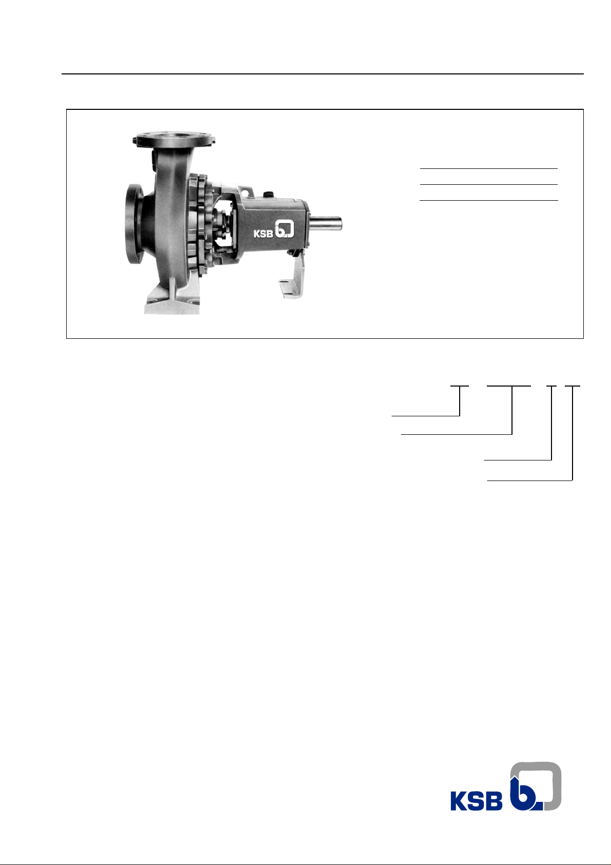
2. Design
Horizontal, single-stage, end suction with top centerline
discharge. The “back-pull-out”design allows maintenance
and repair services through the backside, without
dismantling piping supports.
Dimensionally built to ISO 2858/DIN 24256 and
mechanically to ANSI B73.1.
Line :
Standard :
Mega
ISO 2858
3. Designation
Trade Mark
Model / Type
Discharger Nozzle Diameter (mm)
Nominal Impeller Diameter(mm)
KSB Meganorm 80 - 200
4. Operating data
Sizes - DN 25 up to 150 ( 1 ¼” to 6’)
Flow - up to 3,082 gpm (700 m3/h)
Head - to 460 ft (140 m)
Temperature - to 221ºF (105º C)
Max. Suction pressure - to 145 psi (10 bar)
Speed - to 3,500 rpm
Page 2
5. Introduction
KSB has supplied you with equipment that has been
designed and manufactured with the most advanced
technology. Due to its simple and tough construction it will
not need much maintenance. With the aim of provid ing our
clients with a satisfactory, trouble free operation, we
recommend to install and care our equipment according to
the instructions contained in this service manual.
Place for description
of type and size of
the pump.
Meganorm
This manual has been prepared to inform the end user
about the construction and operation of our pumps,
describing the adequate procedures for handling and
maintenance. We recommend that this manual should be
handled by the maintenance supervision.
This equipment should be used in the operational
conditions for which it was selected as to: flow rate, total
head, speed, voltage, frequency, and temperature of
pumped liquid
Place for description
of manufacturer data.
Place for order number
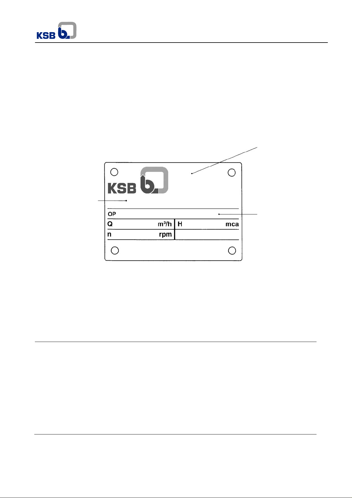
Fig. 1 –Nameplate
For requests about the product, or when ordering spare
parts, please indicate the type of pump and the Production
Order nº (serial nº). This information can be obtained from
the nameplate on the actual pump. If the nameplate is not
available, the PO nº is engraved in low relief on the suction
flange, and on the discharge flange you may find the
Attention
instructions and recommendations. Its careful reading
is an obligation before installation, electrical
connections, first starting and maintenance.
: This manual contains very important
impeller diameter.
Contents
Denomination Chapter Denomination Chapter
Application
Design
Designation
Operating data
Introduction
Technical data
Transportation
Preservation and storage of idle pumps
1
2
3
4
5
6
7
8
Installation
Operation
Maintenance
Explode view/Parts list
Recommended spare parts
Special recommendations
Pressure limit x Maximum temperature
Wearing areas maintenance
9
10
11
12
13
14
15
16
2
Page 3
Meganorm
6. Technical data
Pump sizes
Units.
100-250 *
100-315
100-400 e
125-200 *
125-250
125-315
125-400 e
150-200
150-250
100-160
100-200 d
65-315
80-315
40-315
50-315
80-200 d
65-250 d
50-125
32-160
32-200.1 d
32-200 d
40-125
32-125.1
32-125
Technical data
Bearing bracket A 30 A 40 A 50 A60
25-150
32-160.1
25-200 d
40-160
40-200 d
50-160
32-250 d
50-200 d
80-160
65-160
65-200 d
50-250 d
40-250 d
65-125
32-250.1 d
80-250 d
80-400 e
150-315
150-400 e
mm
Width of impeller
passage
WR2 with water
Max. rot. speed rpm 3500 1750 3500 1750
Max. suction pressure bar/(psi) 10 / (145) d e
Max. discharge pressure
x Temp.
Packing
Shaft
Seal
Mech. seal f inch 1 3/8 1 3/4 2 3/8 2 3/4
Axial thrust balance Min./max. flow - 0.1 Qopt / 1.1 Qopt 0.15 Qopt / 1.1 Qopt
Flanges - ANSI B 16.1 125 Lb FF 250 Lb FF
Rotation direction - Clockwise, seen from driver end
Bearings
inch
kg m²
lb.ft
bar/(psi) See table 7
mm 10 12,5
inch 3/8 1/2
Ball bearings 2x
6 7 9 5 5 6 6
5,5
3/16
4/16
0.0214
0.0591
2
0.127
0.350
c
4/16
6/16
0.0140
0.0142
0.083
0.084
14
12 9 20
3/16
3/16
4/16
4/16
9/16
8/16
6/16
13/16
0.0224
0.0238
0.0760
0.0786
0.0144
0.0336
0.0640
0.0189
0.132
0.141
0.451
0.466
0.085
0.199
0.379
0.112
6306 C 3 6308 C 3 6310 C 3
16
11
7/16 1 5/16
10/16
0.0394
0.0750
0.233
0.445
8 8 8
25
0.0263
0.1800
0.156
1.068
12
21
17
5/16
5/16
8/16
13/16
11/16
0.1820
0.1880
0.1920
0.0521
0.0985
1.079
1.115
1.139
0.309
0.584
By bored hole on impeller
125LbFF
9
31
6/16
1 4/16
0.0641
0.4396
0.380
2.608
y y y yy
9
13
6/16
8/16
0.4800
0.2232
2.847
1.324
23
19
14/16
12/16
0.1568
0.2904
0.930
1.722
36
32
1 7/16
1 4/16
0.1040
0.1800
0.617
1.067
13
18
13
27
23
8/16
8/16
10/16
14/16
1 1/16
0.5120
0.5696
1.2788
0.3172
0.6100
3.037
3.379
7.587
1.881
3.619
ANSI B 16.1 125 Lb FF
17
40
11/16
1 9/16
1.3832
0.2230
8.206
1.323
37
30
1 7/16
1 3/16 1 2 5/16
0.4100
0.7740
2.432
4.592
25
59
1.6912
0.2918
1.731
10.033
48
39
1 9/16
1 14/16
0.4656
0.8680
2.762
5.149
6312 C 3
33
1 5/16
1.8600
11.035
Drive (P/n value)
Shaft SAE 1045
Weight Cast iron
Lubrication
HP/rpm 0.0176 0.0458 0.100
kg
32
40
34
35
34
34
42
44
38
38
49
40
42
47
49
68
68
73
lb
70
88
75
77
75
75
92
97
84
84
88
92
108
104
108
150
150
161
72
159
70
154
Oil
61
134
89
196
104
229
108
238
89
196
92
202
106
233
105
231
108
238
126
278
132
291
162
357
132
291
142
313
178
392
136
300
157
346
156
344
Table 1 y125Lb FF yy250 Lb FF
*For sizes 100-250 and 125-200 max. speed = 2.900 rpm.
cFor size 25-200 by bored holes on impeller, for sizes 25-150; 32-125.1 and 32-12 5 without axial thrust balance.
deThe maximum suction pressure for pumps with mechanical seal is 5 bar (73 psi), except for sizes d in 3500 rpm
and e in 1750 rpm which are limited by sum of inlet pressure and work pressure not exceeding 10 bar (145 psi).
fMaterials: stationary face in ceramic, rotating face in carbon, seals in Buna-N.
Not recommended for liquids containing solids.
Other materials upon request.
193
425
183
403
192
423
3
0.158
246
542
280
617
Page 4
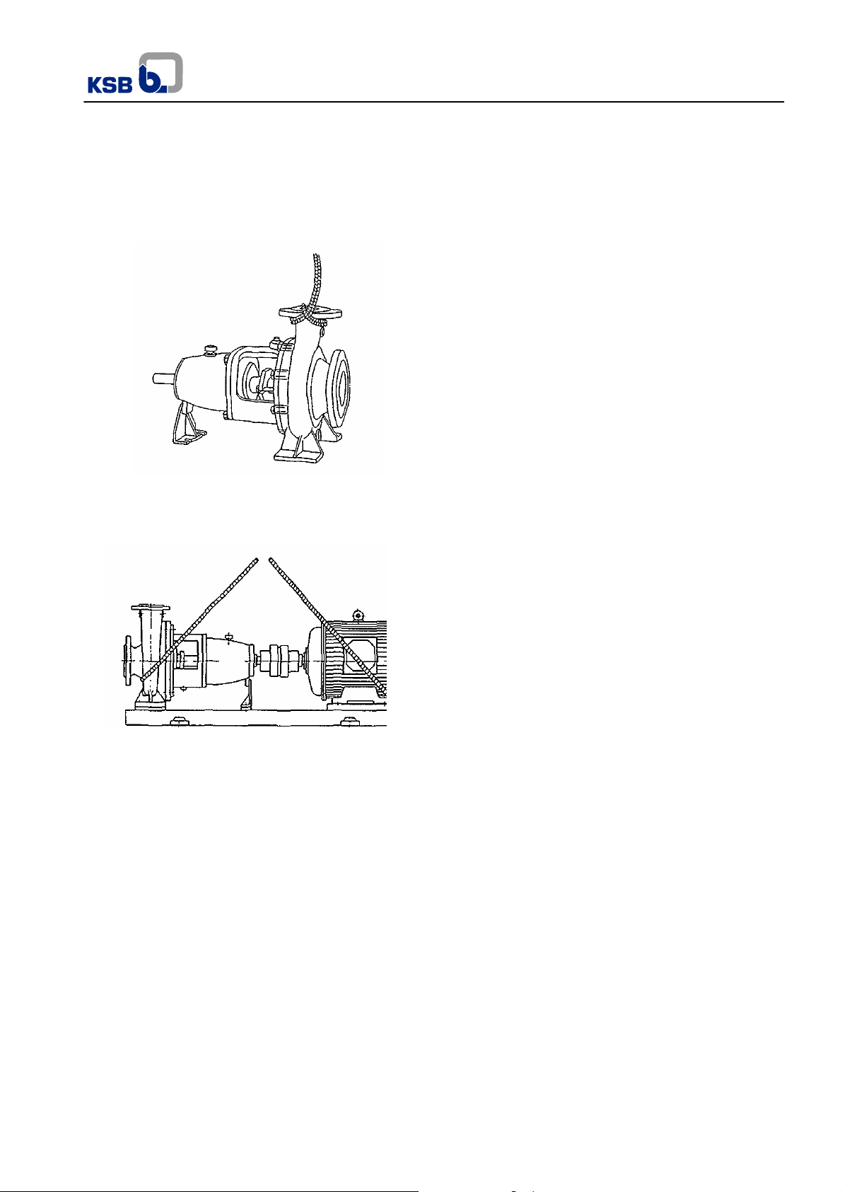
7. Transportation
Skilled, trained personnel should perform the transportation
of the pump-motor assembly or bare shaft pump. Even so,
safety regulations should be observed. On lifting, the motor
lug should be used to carry the motor only and never the
pump-motor assembly.
Fig. 2 – Transportation of the pump through the discharge
flange.
Fig. 3 – Transportation of the pump-motor assembly
Be sure that the coupling guard and foundation bolts
NOTE:
are not lost or damaged during transportation.
8. Preservation and storage of idle
pumps
Following procedures of preservation and storage are made
by KSB and its Dealer Network and protect the equipm ent
up to 6 months in an indoor environment. It is client
responsibility to keep these procedures after receiving the
pump.
When the pump is not subjected to a performance test after
its sale, the areas in contact with the pumped liquid which
are not painted (i.e. stuffing box housing, wear rings, flange
sealing areas, etc), receive an application of RUST ILO DW301 by brush.
When the pump is equipped with packing and is subjected to
a performance test, it is drained after the test without
Meganorm
disassembling it, and then filled up with RUSTILO DW-
301 rotating its rotor assembly in order to improve
RUSTILO application. After this operation, the pump
should be drained again.
Exposed shaft areas (i.e. shaft end, area between the
gland cover and the bearing bracket) receive a brush
application of TECTYL 506.
On oil lubricated bearing brackets, the bearings receive
a layer of MOBILARMA 524 by spray.
The pump must be protected against material damage,
humidity, dust and aggressive environment i n an i ndoor
place.
8.1 Additional procedures of preservation and
storage of idle pumps
- Pumps stored for periods exceeding one year
should be serviced every 12 months. They should
be disassembled, cleaned and the whole
preservation process described below should be
repeated.
- PACKING equipped pumps should have their
packing removed before storage.
- MECHANICAL SEALS should be cleaned by
compressed air. No other liquid or material
should be applied to them in order to prevent
damage to the secondary sealings as to o-ring
gaskets.
- All connections as inlets for liquids from external
sources, priming, draining, flushing and cooling
should be closed. SUCTION AND DISCHARGE
FLANGES SHOULD BE COVERED to prevent the
entry of strange bodies.
- Assembled pumps waiting to be installed or to start
operation should be turned manually every 15
days. If it is difficult to move them by hand, use a
box spanner, protecting the shaft surface at the
point of application.
- Before conservation liquids application, areas
should be washed with gasoline or kerosene until
they are completely cleaned.
4
Page 5
Characteristics of the protecting liquids used for pump preservation purposes:
Protecting liquid
Thickness of the applied
layer (μm)
Drying time Removal Manufacturer
Meganorm
TECTIL 506 from 80 to 100 ½ up to 1 hour
RUSTILO DW 301 from 6 to 10 1 up to 2 hours Gasoline, benzene Castrol
MOBILARMA 524
≤ 6
Table 2 – Protecting liquids
9. Installation
Our pumps should be installed, leveled and aligned b y skill ed
and trained personnel. When this service is done incorrectly,
it will originate operational troubles, premature wear and
damage beyond repair.
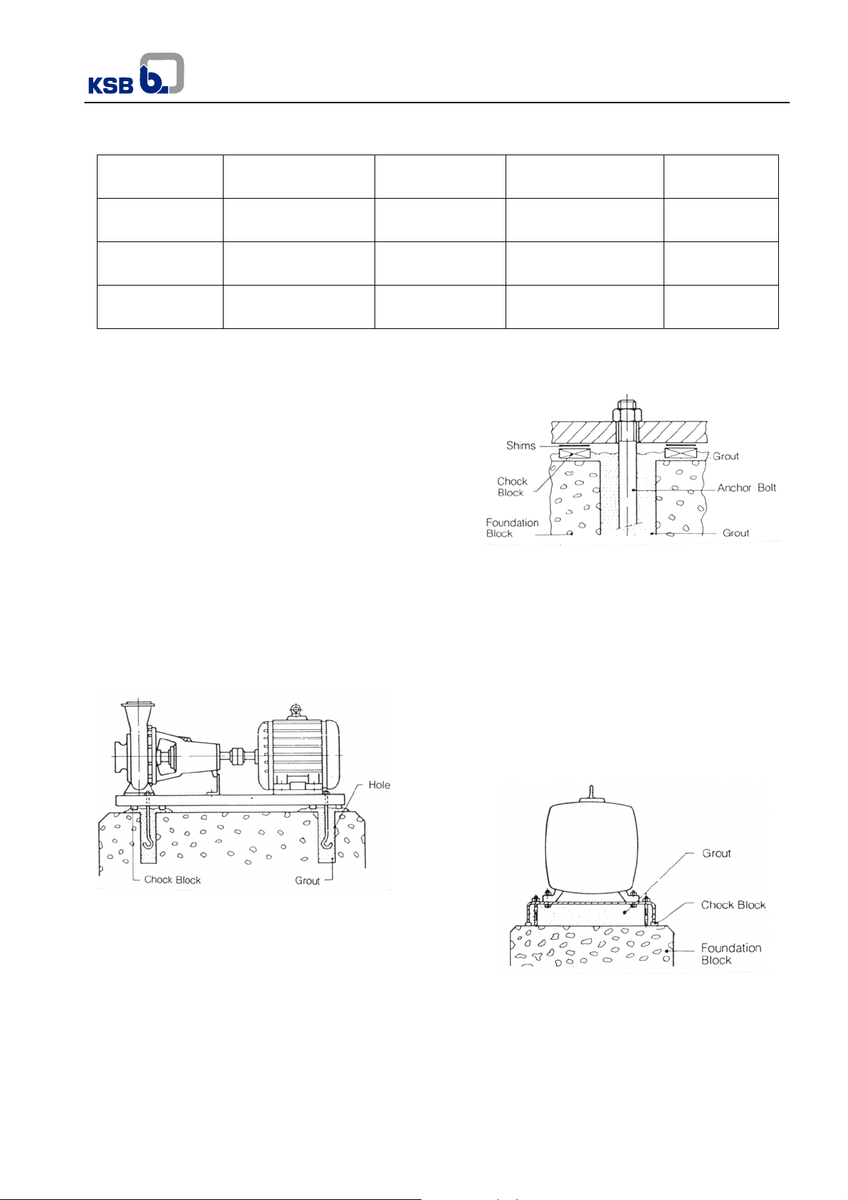
9.1 Base grouting
Place the foundation bolts in the holes or slots of the
foundation block according to boring design as shown on the
foundation drawing.
Between the base and the foundation block and beside the
foundation bolts, metallic chocks of the same height should
be fixed with grout together with the foundation bolts, to
serve as support for the base.
In order to achieve a perfect adherence to the grout, the
chock blocks and foundation bolts should be free of any
grease or oil residues. After the grout set is compl eted, place
the base on the foundation block (non-shrinking mortar is
highly recommended). Please see Fig. 4.
does not dry Not necessary Mobil Oil
.
Note: After leveling the base and before concrete fulfill, the
motor-pump set must be pre-aligned according to the
instructions of item 9.4.
9.3 Grouting
In order to get a good, vibration-free operation, the pump
base plate must be filled with grout.
Grout should be made of specific compounds available in the
civil construction market, which prevent shrinkage through
grout setting process as well as full base filling and does not
allow blanks or gaps. Please see Fig. 6a
Gasoline, benzene
diesel Oil
Fig. 5 – Base leveling
Brascola
Fig. 4 – Base grouting
9.2 Base leveling
Check if the base plate is equally resting on its chock blocks,
if it is correctly set, place and tighten uniformly the nuts on
the foundation bolts. With the help of a precision lev el, check
the leveling of the base longitudinally and transversally.
If the base plate is out of level, loosen the foundation bolt
nuts and insert shims, as necessary, between the metallic
chock block and the base, in order to correct the leveling.
Please see fig.5.
Fig. 6a-Base fulfill with grout
9.3.1 Execution with adjustment screws
When adjustment screws are used under motor side
surrounding areas should be free of concrete. Protecting
tubes should be used, in order permit future adjustments to
align the equipments. See fig.6b.
5
Page 6

Fig. 6b – Grouting inside the baseplates of adjusting screw
type
9.4 Coupling alignment
The useful life of the rotating assembly and its operation free
of irregular vibrations will rely on the perfect alignment
between the pump and the driver.
The alignment performed at the factory must be rechecked
due to the fact that during transportation and handling, the
motor-pump assembly is subjected to deformations, which
may affect the initial alignment.
After the complete set of the grout, perform the alignment, if
possible, with the suction and discharge pipe lines already
connected.
This alignment should be performed with the help of a dial
indicator for the control of the radial and axial displacements.
Fix the button of the instrument to the periphery of on e the
coupling halves, adjust the position of the feeler
perpendicular to the periphery of the other half of the
coupling. Move the dial to zero and move manually the
coupling half in which the instrument button is fixed, making
the dial complete a 360 degrees turn. Please see Fig.7.
The same procedure should be performed to control the axia l
displacement. Please see Fig.8.
Fig. 7 Fig.8
Radial control Axial control
To correct the alignment, loosen the driver bolts an d move
driver laterally or insert shims to adjust height as required.
Axial and radial alignments should remain within a tolerance
of 0.1 mm with the pump and driver set screws tighten
securely.
If there is no dial indicator available, use a straight edge
placed across the two rims of the sleeve coupling. To control
Meganorm
axially use a feeler gauge. Please see Fig. 9. Observe the
sleeve coupling hub clearance specified by manufacturer.
Fig. 9 – Alignment with straight edge and feeler gauge
9.4.1 Motors without adjustment bolts
For the alignment correction, loosen the bolts from the dri ve
replacing them laterally, or insert shims to correct the height
as required.
9.4.2 Motors with adjustment bolts
To realign the coupling, first loose the four dr ive bolts, as well
as the lock nuts. Turn the adjustment bolt by hand or with a
tool until the coupling alignment is correct. Retighten the bolts
and respective nuts.
9.5 Suction pipeline – Recommendations
To install the suction piping follow these instructions:
a) Connect the suction piping to the pump only after the
complete hardening of the grout in the base plate.
b) The suction piping should be as straight and short as
possible – reducing pressure losses - and totally air tight,
preventing any air leaks.
c) In order to be free of air pockets, the horizontal section of
the suction piping, when negative, should be installed with
gradual rise slope. When positive, the horizontal section
of the pipeline should be installed with a gradual rise
slope to the suction tank.
d) The nominal diameter of the pump suction flange does not
determine the suction pipe nominal diameter. To calculate
the ideal diameter as a reference, the liquid velocity ca n
be defined between 3.2 ft/s and 6.5 ft/s (1 and 2 m/s).
e) If it were necessary to use a reduction, it should be
eccentric, mounted with its taper facing downwards, so
that the reduction upper generatrix stays in a horizontal
position coincident with the pump generatrix, so as to
prevent air pockets.
6
Page 7

f) Curves and accessories, when needed should be
designed and installed reducing pressure losses to a
minimum, i.e. always prefer long or medium radius
curves.
g) The suction line flange should fit to the pump suction
flange without any stress or tension and without applying
any kind of force to the casing. The pump should never
be an anchor point for the suction pipeline. If this
condition is not observed a misalignment may happen,
originating cracks on pump parts and/or other severe
damages.
h) On installations equipped with foot valve, observe that the
free passage area should be 1.5 times the cross sectional
area of the suction pipeline. Normally coupled to the foot
valve there should be a suction strainer with a free
passage area 3 to 4 times larger than the cross section al
area of the suction pipeline.
i) When the liquid being pumped has large temperature
variations, expansion joints should be installed preventing
the effects of contractions and expansions of the suction
pipeline on the pump.
j) With positive suction, it is advisable to install an inlet
valve to close the flow to the pump when necessary.
During the pump operation it should stay totall y open. A
suction with a common header for several pumps should
have an inlet valve for each pump and the connection
between the header and each suction line should be
made with line angle changes less than 45 degrees. In all
these applications of gate valves, the valve stems should
be directed either horizontally or vertically downwards.
k) To prevent turbulence, leakage of air, sand or mud at the
pump suction, all recommendations of the HYDRAULIC
INSTITUTE referred to the these types of installation
should be strictly observed.
l) Even if the coupling alignment has been checked before
tightening, it has to be repeated after the final tightening
of the suction pipeline.
m) To facilitate the mounting of the suction pip eline and the
fitting of the parts, install as necessary, flexible joints of
the following types: Dresser, common or special with tie
bolts.
Meganorm
Fig.11 Positive suction
9.6 Discharge pipeline – Recommendations
To install the discharge pipeline, please follow the instructions
below:
a) If the overpressures caused by the returning of the liquid
in long pipe lines, exceed the limits specified for the line
and the pump, water hammer control devices should be
installed on the discharge pipe line.
b) When the diameters of the pump and pipeline flanges are
different, the connections should be done through a
concentric reduction.
c) On the points where it is necessary to bleed the air in the
pipeline, vent valves should be installed.
d) Install a discharge valve, if possible immediately after the
discharge nozzle of the pump in order to pr operly control
the flow rate and pressure or to prevent driver overloads.
e) When a non-return valve is installed, it should be mounted
between the pump and the discharge valve, preva iling t his
condition over item D.
f) Tie mounting joints should be installed to absorb the
system reaction forces, originated on the applied loads.
g) Safety valves, pressure relief devices and other
operational valves not included up to now, should be
installed as necessary for adequate operation of the
pipeline.
h) The recommendations for the suction pipeline described
on items A, B, F, G are also valid for the discharge
pipeline.
Fig.10 – Negative suction
7
Page 8

9.7 Auxiliary piping and connections
Fig. 12 – Auxiliary piping and connections
Dimension – NPT
Thread Connection Designation
A30 A40 A50 A60
1M.1 Manometer
1M.2 Manometer
3M
6B.1 Drain
8B Dripping
6B.2 Base drain
13D
13B
9.8 Coupling guard
For increased safety in operation, coupling g uards should be
installed. They are made of steel or brass and fixed to the
base.
Check that the coupling guard is not in touch with moving
parts.
Vacuum pressure
gauge
Lubrication
Drain
Table 3
1/4 1/4 1/4 1/4
1/4 1/4 1/4 1/4
1/4 1/4 1/4 1/4
3/8 3/8 1/2 1/2
1/2 1/2 3/4 3/4
1 1 1 1
Ø 20 mm
1/4 1/4 1/4 1/2
9.9 Instruments
It is recommended to use pressure gage and vacuum meter
on discharge and suction pipes respectively for a better
operation control.
Meganorm
Their ranges must correspond to 150% of highest pumping
pressure.
Instruments must be equipped with valves.
When pumping chemicals and agressive liquids, the
instruments and their valves should be made of proper
materials.
In order to obtain a longer useful life the valves should be
open only to read the instruments and then closed again.
10. Operation
10.1 First starting procedure
The following items must be provided for pump first startup:
a) Pump and its driver must be securely fastened to the base
plate;
b) Fix firmly the suction and discharge pipelines;
c) Connect and run auxiliary pipelines and connections (if
any).
d) Wiring should be done upon assuring that all motor
thermal overload protections are securely and adequately
connected and set.
e) Check bearings for cleanliness and dampness. Fill
bearing bracket with oil in quantity and quality as specified
in item 11.
f) Check the rotation direction of driver without coupling the
pump to avoid dry operation.
g) Manually check for the free running of the moving parts.
h) Check that the proper coupling alignment according to
item 9.4 has been performed.
i) Mount coupling guard (if any).
j) Prime p ump by filling it and suction pipeline with water or
with the liquid to be pumped, bleeding internal air
simultaneously.
k) Check that the gland cover nuts are just fitted, without
tightening them (pumps with packing).
l) Fully open suction valve (if any) and close discharge
valve.
10.2 Immediate steps after first start-up
Once the pump has started and is already in normal
operation, please follow the instructions below:
a) Adjust pump to its operation point (pressure and flo w) by
opening slowly the discharge valve shortly after pump
drive has reached its nominal speed.
8
Page 9

b) Motor current consumption (amperage) must be controlled
as well as network voltage value.
c) Assure that suction pressure value corresponds to the
designed one.
d) Assure that pump runs vibration-free and without unusual
noises. Vibration criteria in accordance to Hydraulic
Institute.
e) Check bearing temperature that may reach 122ºF (50ºC)
over ambient temperature. However the sum of bearing
temperature and ambient temperature should not exceed
197ºF (90ºC).
f) Adjust the packing by tightening gland cov er nuts ab out 1/6
turn. Like any new packing, it is required a certain period to
set. The new packing should be checked during the first 5
to 8 hours of operation and in the event of leakage in
excess, the gland cover nuts should be tightene d about 1/6
turn again. During normal operation, packing should drip.
When packing reach the set stage, a weekly inspection
should be enough. The procedure mentione d above shoul d
be practiced every 15 minutes over the first 2 hours of
operation. If all tests pass, new checking should be carried
out every hour, until the first 5 to 8 running hours (p umps
with packing).
g) At the operation beginning, the pum p with mechanical seal
may have a little leakage through that. This leakage must
stop after sealing faces accomodation.
10.3 Operation supervision
Depending on the availability of personal and on the
importance of the pump, we recommend the following
supervision. In case of any irregularity, the maintenance
supervisor should be called immediately.
10.3.1 Weekly supervision
Check:
a) Operating point of the pump.
b) Electric motor consumed current and network voltage.
c) Suction pressure.
d) Vibrations and irregular noises.
e) Oil level.
f) Packing leakage.
10.3.2 Monthly supervision
Check:
a) Oil change interval. Consult chapter 11.2.
b) Bearings temperature.
Meganorm
10.3.3 Semestral supervision
Check:
a) Fixing bolts on pump, driver and base.
b) Alignment of the motor-pump assembly.
c) Coupling lubrication (if an y).
d) Replace packing if necessary (if any).
e) Check the mechanical seal (if any), if their sealing
faces are worn-out, scratched or broken. Replace it if
necessary.
10.3.4 Annual supervision
a) Disassemble the pump for maintenance. After
cleaning, inspect condition of ball and roller bearings
(very carefully), radial seal rings, gaskets, o-rings,
impellers, internal areas of the volute casing (check
also thickness), wear areas and coupling.
10.4 Shutdown procedure
Follow in sequence these instructions:
a) Shut off pump discharge valve.
b) Turn off the driver and observe the gradual and
smooth stop of the rotating assembly.
c) Close the suction valve (if any).
d) Close the auxiliary pipelines (if there is no restriction).
11. Maintenance
11.1 Bearing maintenance
Maintenance purpose here is to increase bearing system
useful life as long as possible. While pump is operating,
the maintenance consists in controlling the ball bearings
temperature and the bearing bracket oil level.
The pumps are delivered from the factory without oil
in the bearing bracket.
NOTE: Table of oil quantity to fill KSB MEGANORM
pumps bearing bracket.
Bearing Bracket Oil quantity - ml (in
A 30 100 (6.10)
A 40 170 (10.37)
A 50 200 (12.2)
A 60 480 (29.30)
Table 4
3
)
9
Page 10

11.2 Lubrication Intervals and oil specification
The first oil change should be made after the first 200 or 300
working hours. The next oil change should be made after 1500
or 2000 working hours. This will avoid dirt particles, which have
not been eliminated by cleaning, to contaminate oil and
damage bearings.
Then, oil change should be made every 8000 effective
working hours or at least once a year (the one that
becomes first). Bearings should be washed every 2
years (as a minimum ).
Manufacturer UP to 3,000 rpm
Atlantic Eureka 68 Eureka 46
Castrol HYS PIN AWS 68 HYS PIN AWS 46
Esso Turbine Oil 68 Turbine Oil 46
Mobil Oil DTE 26 DET 24
Ipiranga IPITUR AW 68 IPITUR AW 46
Petrobrás Marbrax TR 68 Marbrax TR 46
Shell Tellus 68 Tellus 46
Texaco Regal R&O 68 Regal R&O 46
Promax
Bardhal
11.3 Packing maintenance
If the packing has already been pressed an equivalent of one
packing ring thickness and even so the leaking is excessive, it
will need maintenance according to the following instructions:
- Stop the pump;
- Loosen the gland cover and remove it. The removal of
gland cover is easy due to its split design. To remov e it,
just push it in the direction of the bearing cover, and then
pull half of the gland cover to the right and the other half to
the left.
- Remove with the help of a flexible rod all the packing rings
as well as the lantern ring.
- Clean the stuffing box chamber.
- Check the condition of the shaft protecting sleeve. If it is
rough or has grooves that could damage the pack ing, the
sleeve may be remachined on its diameter up to a
maximum of 1 mm, or replaced by a new one.
- Cut new packing rings, if possible with oblique edges (see
Fig. 13). To facilitate this cutting operation a very simple
device may be constructed as shown in Fig. 14.
Maxlub MA 20 Maxlub MA 15
Table 5: Oil specifications
Exceeding 3,000
rpm
Meganorm
Fig. 13 – Slanted cut of the packing
Fig. 14 – Packing rings cutting device
- Lubricate the inner diameter of each packing ring
with grease. Lubricate the outer diameters of the
lantern ring, of the gland bush and of the gland r ing
(if any) with Molykote G;
- Proceed to the assembly in the inverse sequence of
the disassembly, introducing each part into the
stuffing box chamber with the help of the gland
cover. The packing rings should be mounted with
their ends positioned 90 degrees from each other
(see Fig. 15).
Fig. 15 – Ring position with ends positioned 90 degrees
from each other
After all parts have been installed in the stuffing box
chamber, a gap of 0.12" (3 mm) should remain as a gui de
for the gland cover.
11.4 Dismantling instructions
The numbers indicated between parenthesis just after the
name of each part refers to the part list and to the
exploded view drawing (Item 12).
Due to its modern project KSB Meganorm pump offers
several maintenance advantages. The whole set can be
dismantled to the back; bearing bracket, pressure cover
and impeller. The spiral casing (102) and the suction and
discharge piping remain in their place. In case of
installation with spacer coupling, the driver remains also
in its place, during the pump maintenance.
10
Page 11

11.4.1 Dismantling sequence of pump
1) Close the suction and pressure valves. Drain the
pump, taking the threaded plug off. (903.3).
2) Close the valve and disconnect the auxiliary pipi ng (if
any).
3) Remove the coupling cover.
4) Remove the oil level pointer (639) and the threaded
plug (903.6) and drain the oil from the bearing bracket.
5) If the coupling has a spacer, remove it; if it doesn’t
have one, disconnect the sleeve removing the driver.
6) Remove the coupling from the pump shaft, loosening
before the coupling fixing Allen bolt.
7) Loosen the bolts that fix the support foot to the base
plate.
8) Loosen the bolts (901.2) or bolts (901.4) when
necessary.
9) Remove all the set by fastening uniformly the
extracting bolts.
10) Support the overhang side of the set with a piece of
wooden. Lock the shaft using a device in the region of
coupling sleeve key (940.2)
11) Loosen and extract the impeller bolt (906), the flat
gasket (400.4) and the circlip (932).
12) Extract the impeller (230), the key (940.1) and the
gasket (400.1).
13) Loosen the bolts (901.4). Loosen the nuts ( 920.2) and
extract the gland cover (452) (if any). Extract the
discharge cover (163) and the flat gasket (400.2).
Extract the shaft protecting sleeve (524) and the seal
components (433) (if any).
14) Extract the thrower (507) and the key (940.2).
15) Loosen the bolt (901.6) and release the support foot
(183).
16) Loosen the bolts (901.5), extract the bearing cover
(360) and the flat gasket (400.3). Take care not to
damage the radial shaft seal rings (421) which come
outside with the bearing cover.
17) With a piece of lead, strike against the shaft (210)
suction side, in order to make the external surfaces of
the radial ball bearings (321) run inside of the b earing
bracket (330) until the complete extracting.
Meganorm
18a) Extract the parts of the sealing chamber, gland
packing (461) and lantern ring (458). (Pumps with
packing).
18b) Extract the stationary face of mechanical seal (433)
from the pressure cover (163) (pumps with
mechanical seal).
After these instructions are completed, the parts will be
available for analysis and maintenance.
11.4.2 Dismantling sequence of the pump with
mechanical seal and seal gland
Loosen the auxiliary pipings and the s eal gland. Follow
the instructions mentioned in the O&M booklet of the
Mechanical Seal Manufacturer, which will be attached to
the pump, in case of seal supply.
11.5 Assembly instructions
All the parts should be cleaned and deburred befor e the
assembling.
11.5.1 Unauthorized modification and manufacture
of spare parts
Modifications or alterations of the equipment supplied
are only permitted after consultation with the
manufacturer and to the extent permitted by the
manufacturer. Original spare parts and accessories
authorized by the manufacturer ensure safety. The use
of other parts can invalidate any liability of the
manufacturer for consequential damage.
11.5.2 Assembling sequence of the pump
Before the assembly at the shaft, the bearings should be
heated at a furnace or with an oil bath up to a maximum
temperature from 176ºF (80ºC) to 194ºF (90ºC) over the
shaft temperature during 30 minutes, observing the
maximum limit of 257ºF (125ºC).
1) Assemble the radial ball bearings (321) at the shaft.
With a piece of lead, assemble the shaft at the
bearing bracket, from the suction side, making the
external track of the bearing to slide inside the
bearing bracket until it reaches equal
measurements at the both sides of the bearing
bracket in order to allow grooving of the bearing
covers.
2) Assemble the radial shaft seal ring (421) at the
bearing covers (360). Assemble the covers carefully
not to damage the radial shaft seal rings with the
flat gaskets (400.3).
3) Fasten the bolts (901.5). Fit the support foot (183)
and fasten the bolt (901.6) with its washer (554.3).
4) Support the overhang side of the bearing bracket
(330) with a piece of wooden. Introduce the
centrifugal ring at the shaft, without touching the
bearing cover.
11
Page 12

5a) Assemble the studs (902) at the pressure cover (163).
So, assemble the packing (461) at the sealing
chamber (pumps with packing).
5b) Assemble the stationary face of mechanical seal (433)
in the pressure cover (163) (pumps with mechanical
seal).
6a) Assemble the gland cover (452), leaning it against the
nuts (920.2) (pumps with packing).
6b) Assemble the mechanical seal components (433) on
the shaft protecting sleeve (524). Lubricate a l ittle with
oil (SAE 10 or SAE 20) or pure vaseline on the pieces
in contact with the mechanical seal (433) (pumps with
mechanical seal)
7) Assemble the shaft protecting sleeve (524) at the
shaft, having first greased its internal diameter with
Molykote G. Guide the flat gasket (400.2) at the
pressure cover; fit the discharge cover (163) at the
bearing bracket (330) and fix it with bolts (901.4)
(tighten them crossly and uniformly).
8) Assemble the flat gasket (400.1), the key (940.1), the
impeller (230) (grease its internal diameter with
Molykote G), the circlip (932), the flat gasket (400.4),
and the impeller bolt (906).
9) Assemble the key (940.2) at the shaft drive side, lock
the shaft with a device and tight firmly the impeller bolt
(906).
10) Introduce the whole set at the volute casing (102)
guiding the set through the diameter of the pressure
cover (163). Assemble the bolts (901.2) with the
washers (554.1), tightening them, crossly and
uniformly. Check manually if the rotor turn round free.
11.5.3 Pump assembly sequence with mechanical
seal with seal gland
Please see Mechanical Seal O&M Manual, which will be
attached to the pump's manual, in case of mechanical seal
supply.
Meganorm
12
Page 13

12. Exploded view / Part list
12.1 Pumps with packing
Meganorm
Pumps with mechanical seal
Impeller fixing detail
for size 25-150
Fig.16
Fig.17
13
Page 14

Meganorm
Part List
Designation Part nº
Volute casing 102 Shaft protecting sleeve 524
Discharge cover 163
Support foot 183
Shaft 210
Impeller 230
Radial ball bearing 321
Bearing bracket 330
Bearing cover 360
Flat gasket 400.1
Flat gasket 400.2
Flat gasket 400.3
Flat gasket 400.4
Flat gasket (1) 400.5
Radial shaft seal ring 421
Mechanical seal (4) 433
Gland cover (3) 452
Lantern ring (3) 458
Gland packing (3) 461
Casing wear ring 502.1
Impeller wear ring (2) 503
Thrower (3) 507
(1) Only applicable for 25-150
(2) Not applicable for 25-150, 32-125 and 32-125.1
(3) Not applicable for pumps with mechanical seal
(4) Not applicable for pumps with packing
Designation Part nº
Spacer disc (1) 551
Washer 554.1
Washer 554.3
Oil level pointer 639
Hexagon head bolt 901.2
Hexagon head bolt 901.4
Hexagon head bolt 901.5
Stud 901.6
Threaded plug (3) 902
Threaded plug 903.1
Threaded plug 903.2
Threaded plug 903.3
Threaded plug 903.6
Impeller screw 906
Nut 920.6
Nut (3) 920.2
Circlip 932
Key 940.1
Key 940.2
Nameplate 970
13. Recommended spare parts
Spare parts recommended for a continuos 2-year continuous service according to the DIN 24296 Standard.
Number of Pumps (including stand-by ones)
Part nº Designation
2 3 4 5 6 and 7 8 and 9
Quantity of Spare Parts
10 or
more
210 Shaft 1 1 1 2 2 2 20%
230 Impeller 1 1 1 2 2 2 20%
321 Bearing (pair) 1 1 2 2 2 3 25%
330 Bearing bracket - - - - - 1 2 units
421 Rad shaft seal ring (pair) 2 3 4 4 4 5 50%
433 Mechanical seal 1 1 2 2 2 3 25%
461 Gland packing (5 rings) 4 4 6 6 6 8 100%
502 Casing wear ring 2 2 2 3 3 4 50%
503 Impeller wear ring 2 2 2 3 3 4 50%
524 Shaft protecting sleeve 2 2 2 3 3 4 50%
Gasket repair set 4 6 8 8 9 12 150%
Table 6 – Recommended Spare Parts
14
Page 15

14. Special recommendations
14.1 Machining of the impeller external diameter
All impellers made of stainless steel have their vanes
adjusted (sharpened) at the outlet area of the liquid being
pumped, according to the illustration on fig.17, when the
impellers have been trimmed in their external diameter by
machining.
(0.12”)
Meganorm
14.2 Shaft run-out on the impeller region
Verify the shaft run-out. Arrange the bearing bracket
mounted with the shaft on vertical position and check
the run-out on the shaft end with a dial comparator
within the maximum limit of 0,05 mm (0,002”).
(0.787”)
Fig. 17 - Adjusting the Impeller Vanes
15. Pressure limit X Maximum temperature
Shaft sealing
Gland packing
Mechanical seal 194 90 10 / 145
Temperature
º F
-18,4 up to 149 - 28 up to 65 12 / 174
199 93 11 / 160
221 105 10 / 145
Temperature
º C
16. Wearing areas maintenance
Change the wear rings of volute casing and / or casing cove r
(if any) when they are wornout and the impeller in good
condition.
KSB and Dealer Network supply wear rings to repair or as
spare parts to be applied for KSB Meganorm pumps.
These wear rings are supplied with suitable tolerance of the
outside diameter and 2mm (0,05”) of extra material of the
inside diameter.
Note: KSB reserves the right to modify the information presented in this manual without prior notice.
ANSI B16.1 Flange
125 #
Pressure [ bar ] / [psi] Pressure [ bar ] / [psi]
Table 7
16.1 When the exchange mist be made
The wear ring exchange must be made when the
clearance between the impeller and the wear ring is
three times longer than the original clearance that is
0,3mm (0,01”).
ANSI B16.1 Flange
250 #
16 / 232
15
Page 16

KSB Bombas Hidráulicas SA
Rua José Rabello Portella, 400
Várzea Paulista SP 13220-540
Brasil http://www.ksb.com.br
Tel.: 11 4596 8500 Fax: 11 4596 8580
SAK – Serviço de Atendimento KSB
e-mail: gqualidade@ksb.com.br
Fax: 11 4596 8656
Meganorm
A2742.8E/8 09.03.2009
16
 Loading...