

KSB Magnochem-Bloc, Magnochem Supplementary Operating Manual
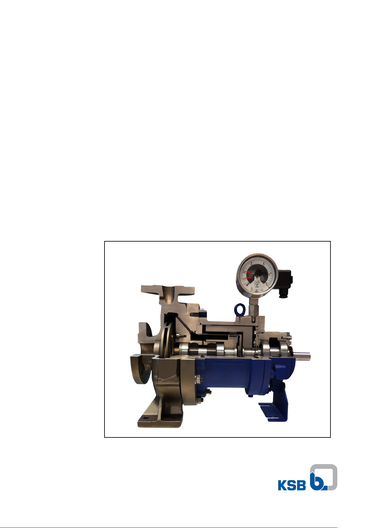
Monitoring Systems
Magnochem
Magnochem-Bloc
Supplementary Operating
Manual

Legal information/Copyright
Supplementary Operating Manual Monitoring Systems
Original operating manual
All rights reserved. The contents provided herein must neither be distributed, copied, reproduced, edited or
processed for any other purpose, nor otherwise transmitted, published or made available to a third party without
the manufacturer's express written consent.
Subject to technical modification without prior notice.
© KSB Aktiengesellschaft, Frankenthal 14.04.2014

Contents
Contents
1 General ..................................................................................................4
2 Temperature Monitoring Sensors ........................................................5
2.1 Temperature monitoring at the containment shroud via the PT100
resistance thermometer
2.2 Temperature monitoring at the containment shroud via a mineralinsulated thermocouple
3 Fill Level Monitoring Sensors .............................................................22
3.1 Monitoring for dry running/formation of a potentially explosive
atmosphere using a level transmitter
4 Leakage Monitor Sensors ...................................................................28
4.1 Leakage monitoring via level transmitter (Liquiphant) ............................... 28
4.2 Leakage monitoring via pressure switch ....................................................... 31
4.3 Leakage monitoring via contact pressure gauge ......................................... 33
4.4 Leakage monitoring via pressure transmitter ..............................................36
...................................................................................5
................................................................................. 14
........................................................... 22
5 Sensor Accessories ..............................................................................40
5.1 Processing of output signals from analog sensors ....................................... 40
5.2 Additional components in potentially explosive atmosphere ..................... 44
6 Related Documents ............................................................................47
6.1 Circuit diagram for PT100 resistance thermometer .....................................47
6.2 Circuit diagram for mineral-insulated thermocouple .................................. 48
Index ....................................................................................................49
Monitoring Systems
3 of 50

Manufacturer's product
literature
1 General
1 General
This supplementary operating manual accompanies the operating/installation
manual. All information contained in the operating/installation manual must be
observed.
Table 1: Relevant operating manuals
Type series Reference number of the operating/installation
manual
Magnochem 2739.8
Magnochem-Bloc 2749.8
For accessories and/or integrated machinery components observe the relevant
manufacturer's product literature.
4 of 50
Monitoring Systems

2 Temperature Monitoring Sensors
2 Temperature Monitoring Sensors
Temperature monitoring of containment shroud
Eddy currents are induced in the metal containment shroud walls of mag-drive
pumps. This causes the metal containment shroud to heat up. The heat loss
generated is dissipated by a secondary circulation flow. The source of the cooling
flow for the rotor space can be internal or external.
▪ With internal circulation, the cooling flow is bypassed from the main flow. The
main flow passes through the pump's hydraulic system.
▪ With external circulation, the cooling flow is supplied to the rotor space from the
outside via auxiliary connections.
Potentially explosive atmosphere
The cooling flow is sufficiently dimensioned for intended operation. The maximum
permissible surface temperature that is dictated by the temperature class to
EN13463-1 is not exceeded (temperature class and maximum permissible operating
temperature as specified in the data sheet). An impermissible rise in temperature can
occur at the containment shroud when the cooling flow is insufficient or fails
completely.
An insufficient cooling flow or failure of the cooling flow can be caused by the
following:
▪ Fluid properties
▪ Pressure too low
▪ Desynchronisation of magnetic coupling
The maximum surface temperature occurs at the containment shroud tube in the
magnetic coupling area. KSB offers the following measuring instruments to detect an
impermissible increase in temperature at the containment shroud:
▪ PT100 resistance thermometer
For design and operational reasons, the PT100 resistance thermometer cannot
detect the maximum surface temperature that occurs at the containment shroud.
It can monitor the operating status of the pump. A distinction is made between
the following operating statuses:
–
Intended operation: Temperature at containment shroud OK
– Failure: Temperature at containment shroud too high
▪ Mineral-insulated thermocouple
The mineral-insulated thermocouple can be used to monitor the temperature in
this area.
2.1 Temperature monitoring at the containment shroud via the PT100
resistance thermometer
2.1.1 Function
Resistance thermometers are temperature sensors that measure the change in
electrical resistance of metals with changing temperature. Resistance thermometers
use a very thin layer of platinum film on a ceramic substrate. The nominal resistance
of these measuring elements at 0 °C is 100 ohms.
Interpretation of readings
The nominal resistance of the PT100 resistance thermometer at 0 °C is 100 ohms.
Equation for calculating the resistance value at any temperature (T):
Temperature range: T = 0 - 850 °C
R (T) = 100+0.39083×T -5.775×10⁻⁵×T
2
Monitoring Systems
5 of 50
M16x1,5
SW17
SW19 (G
1
/4)
T = 80 °C
2 Temperature Monitoring Sensors
Sample calculation:
Measured temperature: T = 80 °C
R (T) = 100+0.39083×80 -5.775×10-5×80
2
R (T) = 130.8968 Ω
The PT100 resistance thermometer has a resistance of approximately 130.9 ohms at a
temperature of 80 °C.
T = 20 °C
Measured temperature: T = 20 °C
R (T) = 100+0.39083×20 -5.775×10-5×20
2
R (T) = 107.7935 Ω
The PT100 resistance thermometer has a resistance of approximately 107.8 ohms at a
temperature of 20 °C.
2.1.2 Technical data of PT100 resistance thermometer
Table 2: Selection aid for resistance thermometer
Resistance thermometer
(type)
Pump design Technical measuring specifications
Leakage barrier Cable lengths Output signal 4
None with ≤ 30 m ≥ 30 m
- 20 mA
TR 55 ✘ - ✘ - Ksb-4,13,xx,02 - ✘ ✘ - Ksb-4,13,xx,01 ✘ ✘ ✘ ✘ ✘
PT100 (TR 55)
1)
For cable lengths up to 30 m
6 of 50
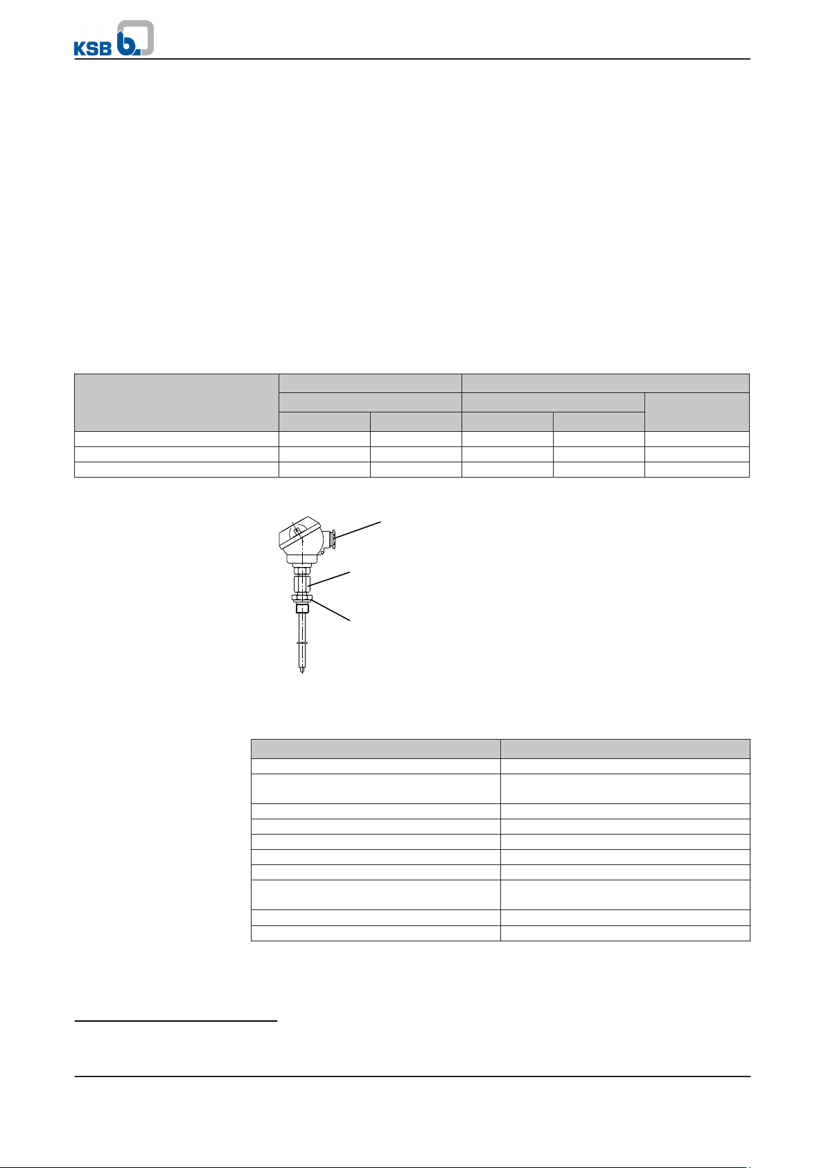
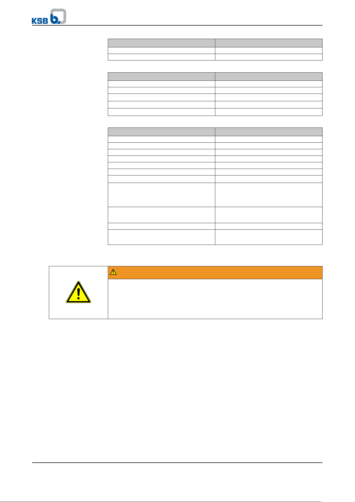
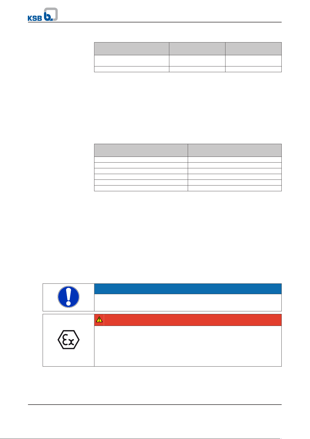
Fig. 1: PT100 resistance thermometer (TR 55)
Table 3: Technical data (TR 55)
Characteristic Value
Sensor type PT100 resistance thermometer
Permissible measuring range (input
-50 ... +450 °C
signal)
Output signal 80 to 268 ohm
Head transmitter None
Type TR 55
Sensor tolerance Class B to IEC 60751
Sealing, sensor tip/support tube Not pressure-proof
Sensor tip Spring-loaded (spring travel approx. 3 to
4 mm)
Wiring
1×4-wire
1)
Process connection G1/4 B/clamping ring
Monitoring Systems
M20x1,5
SW 19 (G
1
/4)
SW 17
2 Temperature Monitoring Sensors
Characteristic Value
Permissible ambient temperature T3/ T4: -40 ... +100 °C
T5: -40 ... +95 °C
T6: -40 ... +80 °C
Nominal length, depending on overall
75, 85 and 125 mm
length
Table 4: Technical data of connection head (TR55)
Characteristic Value
Design, head JS
Enclosure, head IP54
Material Aluminium
Cable connection M16×1.5
Table 5: Characteristic values for explosion protection (TR 55)
Feature Value
Explosion protection, intrinsic safety Ex ib IIC T6
CE conformity marking TÜV 10ATEX 555793 X
Maximum supply current li = 550 mA
Maximum supply power P
maxSensor
= 1.5 W
Maximum supply voltage Ui = 30 V
PT100 (Ksb-4,13,xx,02)
2)
This measuring range only applies when the PT100 resistance thermometer is used for designs with a leakage barrier. A
larger measuring range (-40 to +200 °C) is possible for designs without a leakage barrier. Coordination with KSB required.
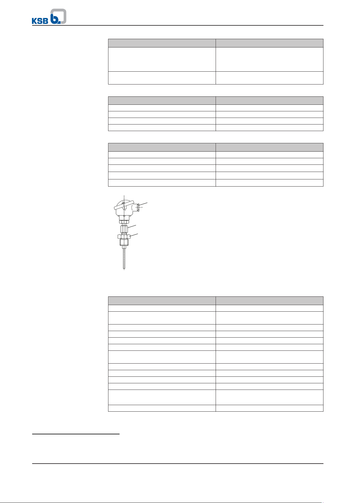
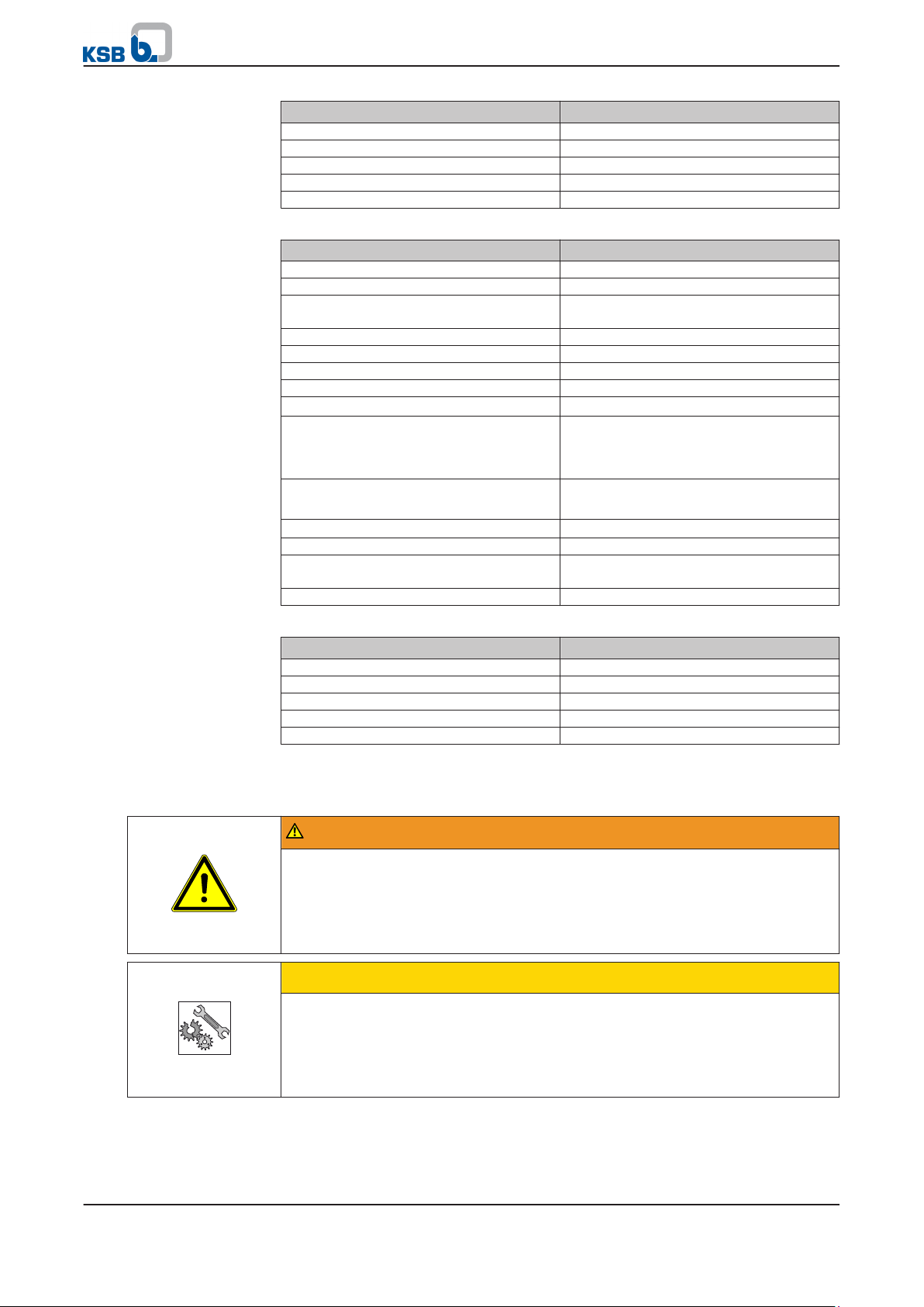
Fig. 2: PT100 resistance thermometer (Ksb-4,13,xx,02)
Table 6: Technical data (Ksb-4,13,xx,02)
Characteristic Value
Sensor type PT100 resistance thermometer
Permissible measuring range (input
-40 ...+120 °C
2)
signal)
Output signal 84 to 146 ohm
Head transmitter None
Type Ksb-4,13,xx,02
Sensor tolerance Class B to IEC 60751
Sealing, sensor tip/support tube Pressure-proof up to 20 bar at a max.
temperature of 120 °C
Sensor tip Spring-loaded (spring travel < 5 mm)
Wiring 1×4-wire
Process connection G1/4B clamping ring
Material: spring-loaded support tube 1.4541
Permissible ambient temperature T5: -40 … +80 °C
T6: -40 … +55 °C
Nominal length, depending on size 120, 135 and 165 mm
Monitoring Systems
7 of 50
M20x1,5
SW 19 (G
1
/4)
SW 17
2 Temperature Monitoring Sensors
Table 7: Technical data of connection head (Ksb-4,13,xx,02)
Feature Value
Design, head BS
Enclosure, head IP65
Material Aluminium
Cable connection M20×1.5
Table 8: Characteristic values for explosion protection (Ksb-4,13,xx,02)
Feature Value
Explosion protection, intrinsic safety 2G Ex ia II C T5/T6
CE conformity marking BVS 03 ATEX E 292
Maximum supply current Ii max = 500 mA (for short circuit)
Maximum supply power P
maxSensor
= 750 mW
Maximum supply voltage Ui = 10 V DC
PT100 (Ksb-4,13,xx,01)
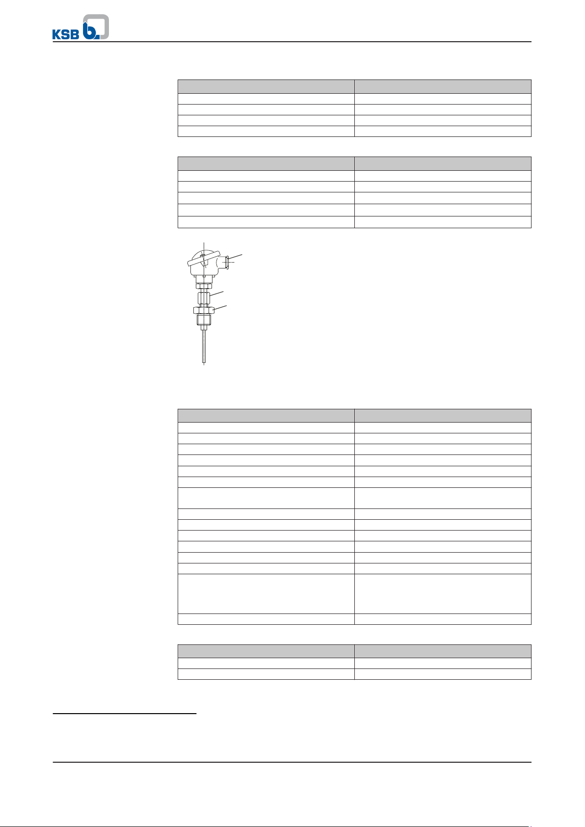
Fig. 3: PT100 resistance thermometer (Ksb-4,13,xx,01)
Table 9: Technical data (Ksb-4,13,xx,01)
Characteristic Value
Sensor type PT100 resistance thermometer
Output signal 4 - 20 mA
Head transmitter T24 WIKA
Permissible measuring range
-40 ... +320 °C
2)3)
Type Ksb-4,13,xx,01
Sensor tolerance Class B to IEC 60751
Sealing, sensor tip/support tube Pressure-proof up to 20 bar at a max.
temperature of 120 °C
Sensor tip Spring-loaded (spring travel < 5 mm)
Wiring 1×4-wire
Process connection G 1/4B clamping ring
Material: spring-loaded support tube 1.4541
Cable connection M20×1.5
Enclosure IP65
Permissible ambient temperature T4: -40 … +85 °C
T5: -40 … +75 °C
T6: -40 … +60 °C
Nominal length, depending on size 120, 135 and 165 mm
Table 10: Technical data of connection head (Ksb-4,13,xx,01)
Feature Value
Design, head BS
Enclosure, head IP65
3)
8 of 50
On designs with a leakage barrier the PT100 resistance thermometer may only be used for temperatures of -40 to 120 °C. If
required, the measuring range may have to be adjusted.
Monitoring Systems
2 Temperature Monitoring Sensors
Feature Value
Material Aluminium
Cable connection M20×1.5
Table 11: Characteristic values for explosion protection (Ksb-4,13,xx,01)
Feature Value
Explosion protection, intrinsic safety 2G E Ex ia II C T5/T6
CE conformity marking BVS 03 ATEX E 292
Maximum supply current Ii max = 120 mA (for short circuit)
Maximum supply power P
maxSensor
= 800 mW
Maximum supply voltage Ui = 30 V DC
Table 12: Technical data of head transmitter
Feature Value
Type T24.10
Design Head-mounted version, explosion-proof
Output Analog, 4 - 20 mA
Fault detection Broken wire, short circuit
Explosion protection 2II 1G EEx ia/ II C T4/T5/T6
Explosion protection type test certificate DMT 02 ATEX E 025 X
Auxiliary energy supply, U
B
DC 9 ... 30 V
Ambient/storage temperature T4: -40 ... +85 °C
T5: -40 ... +75 °C
T6: -40 ... +60 °C
Current-loop circuit (+ and - connections) Ui = 30 V, li = 120 mA, Li = 110 µH
Ci = 6.2 nF, Pi = 800 mW
Material Plastic, PBT, glass-fibre reinforced
Enclosure (to IEC 60529/EN 60529) Housing: IP 66/IP 67
Connection terminals: IP 00
2.1.3 Installing the PT100 resistance thermometer in the pump
WARNING
Leaks and/or corrosion damage on monitoring systems
No fault indications!
Leakage of fluid handled!
▷ Never install damaged or corroded monitoring systems in the pump.
▷ Check monitoring systems for damage and correct function prior to installation.
Monitoring Systems
9 of 50
1 2
3
1
2 Temperature Monitoring Sensors
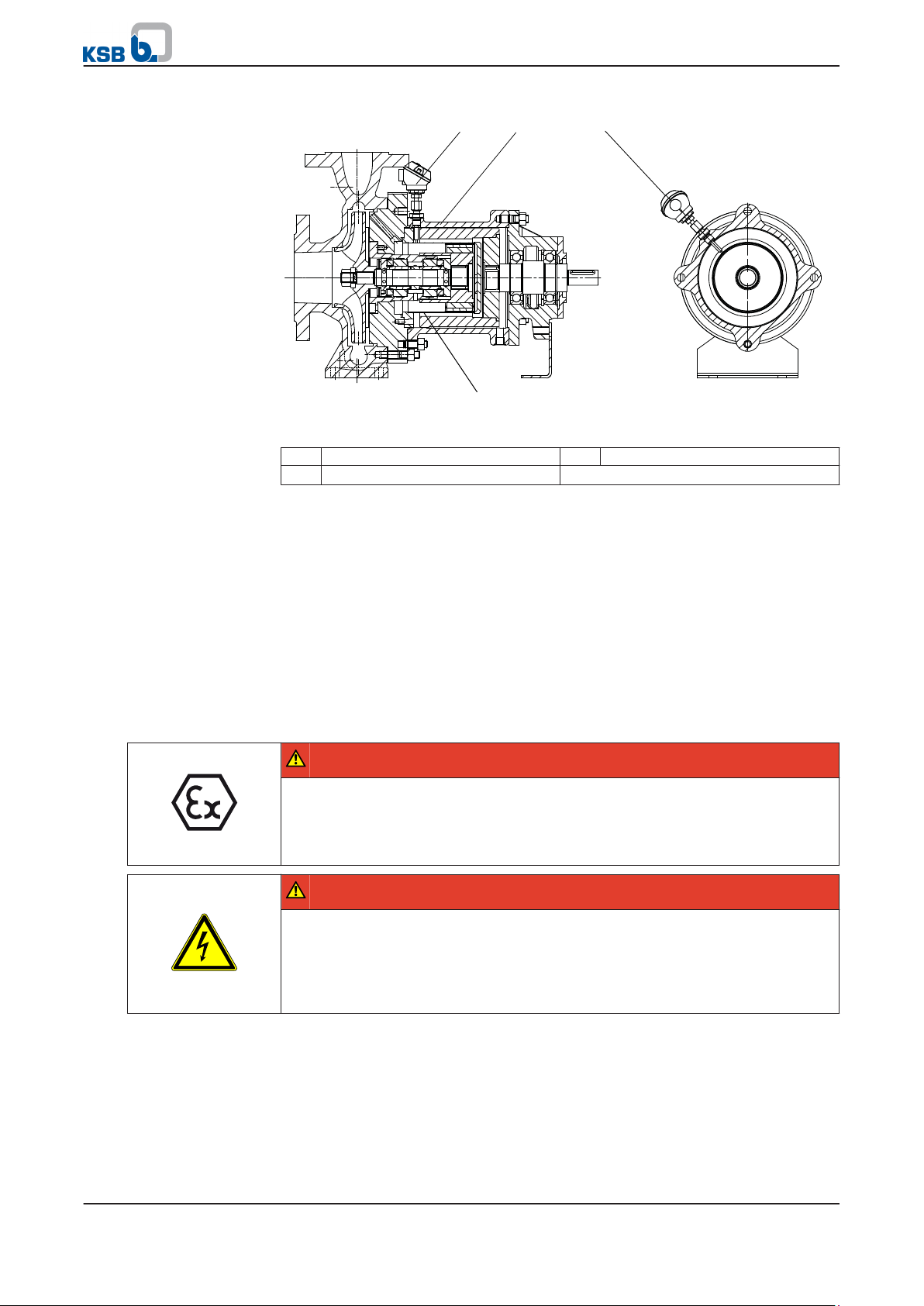
Fig. 4: Installation location of the PT100 resistance thermometer
1 PT100 resistance thermometer 2 Bearing bracket lantern
3 Containment shroud
1. Remove the screw plug from the 4M.3 connection.
2.
Screw the compression fitting up to the stop.
3. Insert the PT100 resistance thermometer into the fitting up to the stop or until
the tip of the resistance thermometer contacts the containment shroud or its
intermediate piece.
4. Turn the connection head of the PT100 resistance thermometer to the required
position.
5. Pull the PT100 resistance thermometer back by approximately 1 to 2 mm.
6. Tighten the compression fitting to prevent the PT100 resistance thermometer
from loosening and rotating.
2.1.4 Electrical connection of the PT100 resistance thermometer
DANGER
Incorrect electrical installation
Explosion hazard!
▷ For electrical installation, also observe the requirements of IEC 60079-11.
▷ Realise a suitable measuring chain.
DANGER
Work on the pump set by unqualified personnel
Danger of death from electric shock!
▷ Always have the electrical connections installed by a trained and qualified
electrician.
▷ Observe regulations IEC 60364 and, for explosion-proof models, EN 60079.
10 of 50
Monitoring Systems
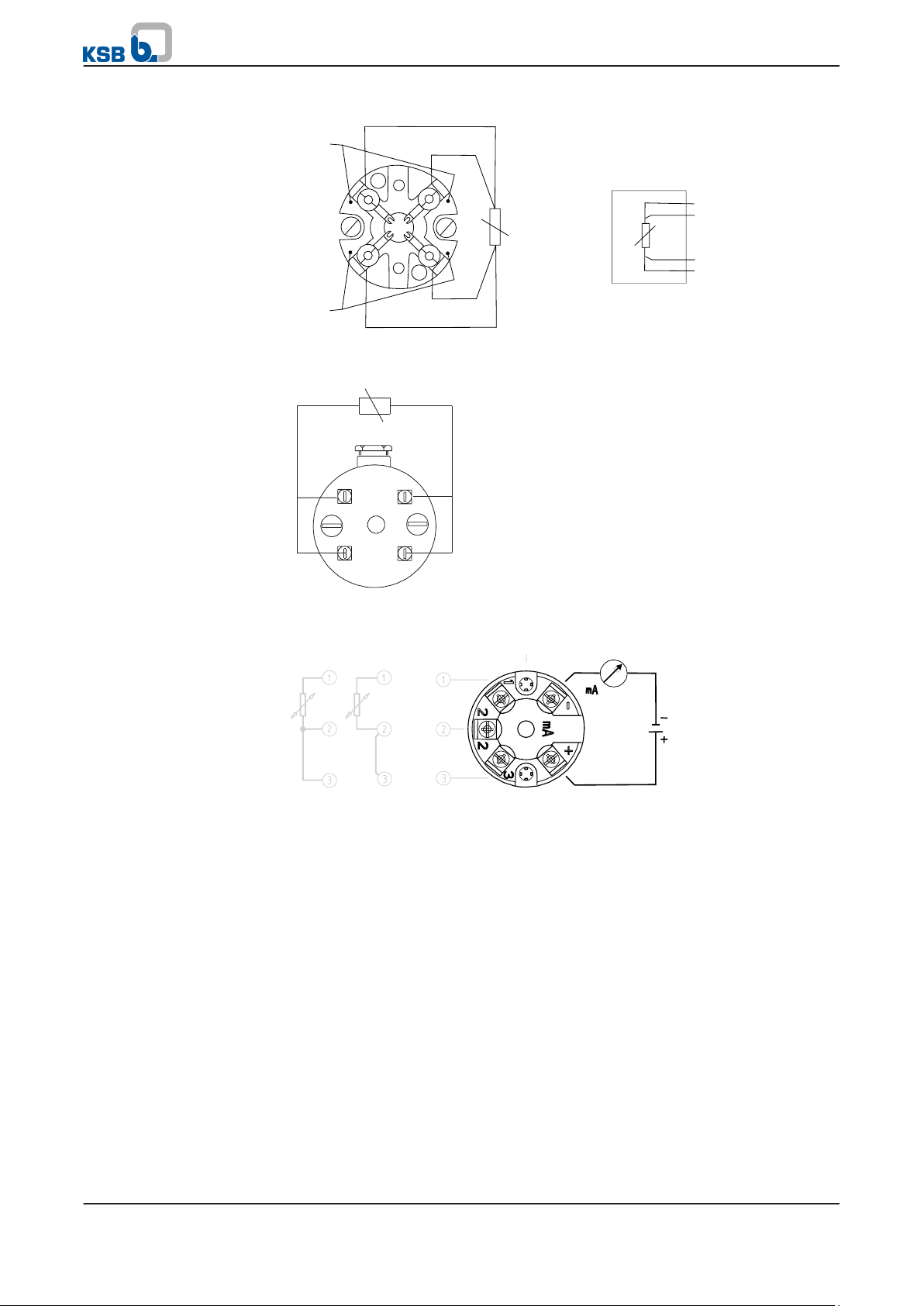
Red
ϑ
ϑ
Red
Red
White
White
White
Terminal assignment, four-
wire system for TR 55
Terminal assignment, four-
wire system for
Ksb-4,13,xx,02
2 Temperature Monitoring Sensors
Fig. 5: Terminal assignment, four-wire system for TR 55
Terminal assignment, four-
wire system for
Ksb-4,13,xx,01 (T24)
Design of measuring chain
Fig. 6: Terminal assignment for PT100 four-wire system, pressure-proof (Ksb-4,13,xx,
02)
Fig. 7: Terminal assignment for PT100 including head transmitter (Ksb-4,13,xx,01 with
T24)
Open the connection head.
1.
2. Connect the PT100 resistance thermometer. (Observe terminal assignment. See
illustrations.)
2.1.5 Design of measuring chain
The design of the measuring chain is influenced by the following factors:
▪ Potentially explosive or non-potentially explosive atmosphere
▪ Output signal (Ω or mA)
The measuring chain must be designed and configured in accordance with these
factors. Observe the following illustration for selection.
Monitoring Systems
11 of 50
(ATEX) barrier
Limit switch
Output signal
in Ω
PT100 resistance thermometer
with ceramic terminal block
4...20 m A
(ATEX) transmitter supply unit
Limit switch
Output signal
PT100 resistance thermometer
head transmitter
Limit switch
Output signal
in Ω
PT100 resistance thermometer
with ceramic terminal block
Measuring chain 1 Measuring chain 2 Measuring chain 3
Non-potentially explosive atmosphere
Potentially explosive atmosphere
4...20 m A
Limit switch
Output signal
PT100 resistance thermometer
with head transmitter
Measuring chain 4
2 Temperature Monitoring Sensors
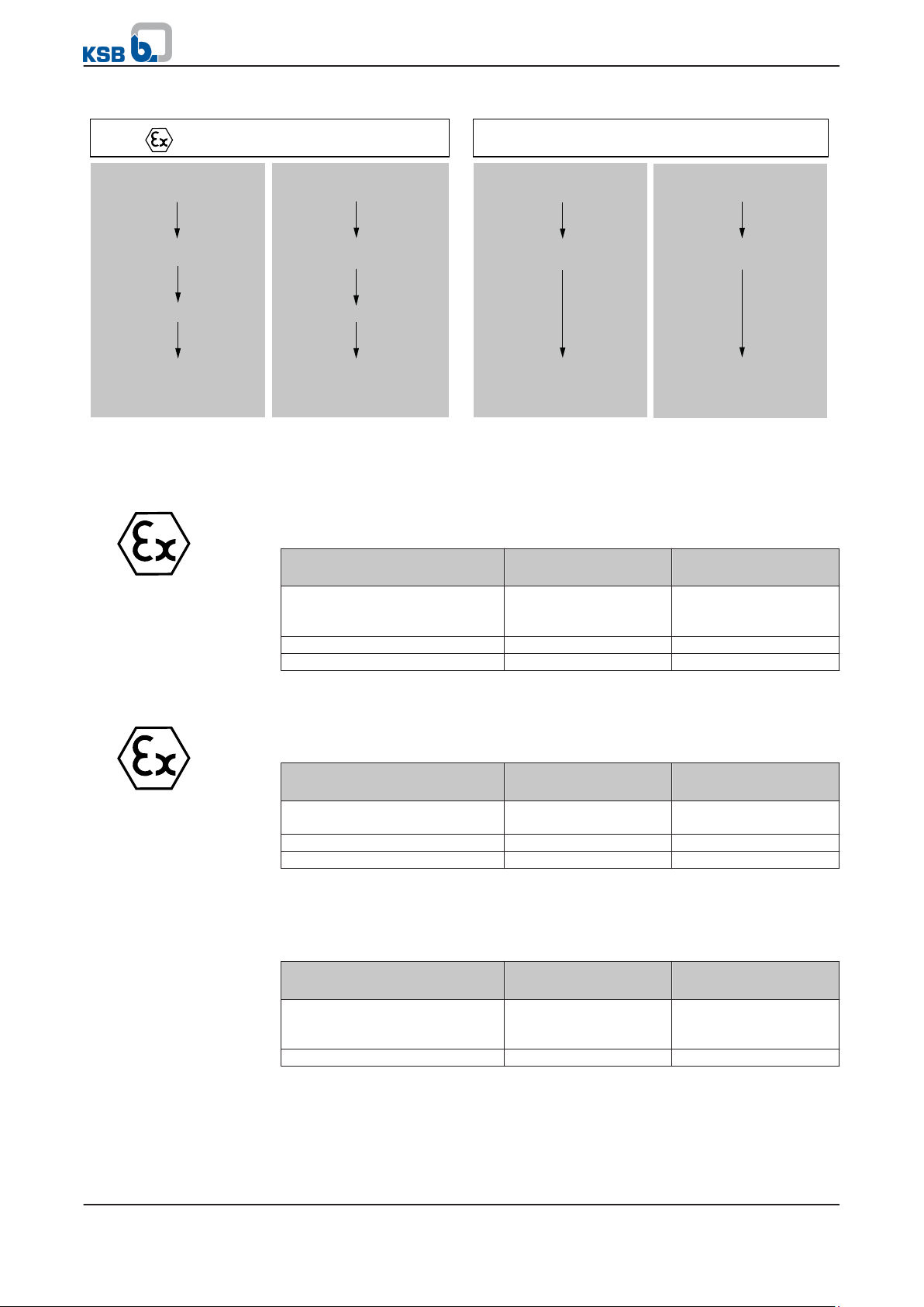
Fig. 8: Design of measuring chain
Non-potentially explosive
atmosphere
Description, measuring chain 1 (potentially explosive atmosphere)
Measuring chain 1 comprises the following elements:
Table 13: Description, measuring chain 1 (potentially explosive atmosphere)
Element KSB device
For details, refer to...
recommendation
PT100 resistance thermometer
without head transmitter
TR 55
or
(⇨ Section 2.1.2 Page 6)
Ksb-4,13,xx,2
(ATEX) barrier Z 954
Limit switch CF1M
(⇨ Section 5.2 Page 44)
(⇨ Section 5.1 Page 40)
Description, measuring chain 2 (potentially explosive atmosphere)
Measuring chain 2 comprises the following elements:
Table 14: Description, measuring chain 2
Element KSB device
For details, refer to...
recommendation
PT100 resistance thermometer
Ksb-4,13,xx,1
(⇨ Section 2.1.2 Page 6)
with head transmitter
(ATEX) transmitter supply unit KFD2-STC4-EX1
Limit switch DGW 1.00 or DWG 4.00
(⇨ Section 5.2 Page 44)
(⇨ Section 5.1 Page 40)
Description, measuring chain 3
Measuring chain 3 comprises the following elements:
Table 15: Description, measuring chain 3
Element KSB device
PT100 resistance thermometer
without head transmitter
Limit switch CF1M or DGW2.0
Description, measuring chain 4
Non-potentially explosive
12 of 50
atmosphere
Measuring chain 4 comprises the following elements:
Monitoring Systems
recommendation
TR55
or
Ksb-4,13,xx,2
For details, refer to...
(⇨ Section 2.1.2 Page 6)
(⇨ Section 5.1 Page 40)
2 Temperature Monitoring Sensors
Table 16: Description, measuring chain 4
Element KSB device
For details, refer to...
recommendation
PT100 resistance thermometer
Ksb-4,13,xx,1
(⇨ Section 2.1.2 Page 6)
with head transmitter
Limit switch DGW 1.00 or DGW 4.00
2.1.6 Analysis of output signals
2.1.6.1 Determining the limit value
(⇨ Section 5.1 Page 40)
In a potentially explosive atmosphere, the maximum permissible surface temperature
is dictated by the temperature class. The maximum permissible operating
temperature of the pump is specified in the data sheet. Observe the following
additional requirements when determining the limit value for the maximum surface
temperature at the containment shroud:
Table 17: Temperature limits
Temperature class to EN13463-1 Maximum permissible surface
temperature at containment shroud
T1 300 °C
T2 290 °C
T3 195 °C
T4 130 °C
T5 On request only
T6 On request only
For design and operational reasons, the PT100 resistance thermometer cannot detect
the maximum surface temperature that occurs at the containment shroud in the
magnetic coupling area. To avoid exceeding the maximum permissible surface
temperatures at the containment shroud (see "Temperature limits" table), a safety
margin to the temperature measured of at least 15 K must be observed. Only the
operating status of the pump can be monitored using the PT100 resistance
thermometer.
A distinction can be made between the following operating statuses:
▪ Intended operation
▪ Failure
Determining the initial value
The initial value and the temperature of the containment shroud or its intermediate
piece during intended operation must first be determined.
NOTE
Observe possible process or rotational speed-related changes in the temperature.
DANGER
Excessive surface temperatures
Explosion hazard!
▷ The limit value for stopping the pump must never exceed the specified surface
temperature of the respective temperature class.
▷ If the specified surface temperature of the respective temperature class is
exceeded, immediately switch off the pump set and determine the cause.
1. Determine the temperature class of the system to EN 13463-1.
Note the maximum permissible surface temperature of the containment shroud
2.
by referring to the "Temperature limits" table.
Monitoring Systems
13 of 50

2 Temperature Monitoring Sensors
3. Transition the pump to the steady state under the intended operating
conditions (see data sheet on the duty point of the pump).
Note the value displayed on the limit switch (= initial value) in the steady state.
4.
5. Check initial value.
The initial value must be at least 15 K below the maximum permissible surface
temperature at the containment shroud (see "Temperature limits" table).
Steady state
Steady state is reached when the temperature rise does not exceed 2 K/h (to EN
13463-1: 2009-07).
If the difference is less, implement the following measures:
▪ Check operating conditions.
▪ Dismantle and clean pump (if required).
▪ Re-determine initial value.
Consultation with KSB/KSB Service is required if the initial value is unchanged.
Determining limit values for operating statuses
Intended operation
The initial value determined corresponds to the temperature at the containment
shroud during intended operation.
Failure
In a failure, an insufficient cooling flow or a failure of the cooling flow can cause the
temperature to rise at the containment shroud. To be able to detect a failure via a
rise in temperature, add a safety margin of 10 K to the initial value determined.
If, during a failure (non-intended operation), the limit value determined is exceeded,
Initial value + 10 K = limit value
the pump is stopped. Depending on the factory setting of the limit switch, the pump
will be started up again after the temperature at the containment shroud has
dropped. The value that is specified as the hysteresis for the output determines the
containment shroud temperature at which the pump is started up again.
A hysteresis of 1 K is factory set for the limit switch CFM1, for example. If the
containment shroud temperature drops 1 K below the limit value here, the pump is
started up again. If the pump must not be re-started after the limit value has been
exceeded, other measures are required on site.
2.2 Temperature monitoring at the containment shroud via a mineralinsulated thermocouple
2.2.1 Functionality of the mineral-insulated thermocouple
The temperature of the containment shroud can be monitored by using an IEC 548compliant mineral-insulated thermocouple fixed to the containment shroud. The
mineral-insulated thermocouple measures in the containment shroud area where the
highest surface temperatures occur: at the containment shroud tube in the magnetic
coupling area. The mineral-insulated thermocouple installed functions as a passive
component in the potentially explosive atmosphere and is designed as a "simple
apparatus" to EN 60079-11.
2.2.2 Technical data of mineral-insulated thermocouple
Table 18: Technical data of mineral-insulated thermocouple with ceramic terminal
block
Characteristic Value
Type K
Explosion protection Intrinsic safety, "simple apparatus" to DIN
EN 60079-11
Sensor type K, NiCr-Ni
Sensor tolerance IEC 584
Measuring point Insulated
Diameter 0.34 mm
Process connection G1/4, compression fitting
Sheath material Austenite steel
14 of 50
Monitoring Systems
2 Temperature Monitoring Sensors
Characteristic Value
Sheath lengths, depending on size 130 and 230 mm
Connection cable material PTFE
Connection cable diameter 3.5 mm
Connection cable length 1 m
Output signal in µV
Table 19: Technical data of head transmitter
Feature Value
Type T12
Design Head-mounted version, explosion-proof
Configuration Pre-configured to type K, NiCr-Ni, IEC 584
ex works
Output Analog, 4 - 20 mA
Fault detection Broken wire, short circuit
Explosion protection II 2 G Ex ib II B / II C T4/T5/T6
Explosion protection type test certificate DMT 98 ATEX E 008X
Auxiliary energy supply, U
B
DC 9 ... 30 V
Ambient temperature T4: -40 °C ... +85 °C
T5: -40 °C ... +75 °C
T6: -40 °C ... +60 °C
Current-loop circuit (+ and - connections) Ui = 30 V, li = 100 mA, Li = 0,65 mH
Ci = 25 nF, Pi = 705 mW
Max. power input For UB = 24 V max. 552 mW
Material Plastic
Enclosure Housing: IP00 IEC 60529/EN 60529
Electronics completely encapsulated
Connection cross-section of terminals 1.5 mm2 max.
Table 20: Technical data of connection head
Feature Value
Type of head BSZ
Enclosure, head IP65
Material Aluminium
Process connection G1/4, compression fitting
Cable connection M20 × 1.5
2.2.3 Installing the containment shroud with fixed mineral-insulated thermocouple
WARNING
Leaks and/or corrosion damage on monitoring systems
No fault indications!
Leakage of fluid handled!
▷ Never install damaged or corroded monitoring systems in the pump.
▷ Check monitoring systems for damage and correct function prior to installation.
CAUTION
Kinking or breaking of the mineral-insulated thermocouple
Damage to the machinery!
▷ Never kink the mineral-insulated thermocouple.
▷ When removing/fitting the bearing bracket lantern, observe the connection
cable of the mineral-insulated thermocouple.
Monitoring Systems
15 of 50
 Loading...