

Page 1
Mag-drive Pump
Magnochem
Installation/Operating Manual
Page 2

Legal information/Copyright
Installation/Operating Manual Magnochem
Original operating manual
All rights reserved. The contents provided herein must neither be distributed, copied, reproduced,
edited or processed for any other purpose, nor otherwise transmitted, published or made available to a
third party without the manufacturer's express written consent.
Subject to technical modification without prior notice.
© KSB Aktiengesellschaft, Frankenthal 06/12/2016
Page 3

Contents
3 of 108
Magnochem
Contents
Glossary .................................................................................................................................................. 6
1 General.................................................................................................................................................... 7
1.1 Principles ...........................................................................................................................................................7
1.2 Installation of partly completed machinery....................................................................................................7
1.3 Target group.....................................................................................................................................................7
1.4 Other applicable documents............................................................................................................................7
1.5 Symbols .............................................................................................................................................................7
2 Safety...................................................................................................................................................... 9
2.1 Key to safety symbols/markings.......................................................................................................................9
2.2 General..............................................................................................................................................................9
2.3 Intended use ...................................................................................................................................................10
2.4 Personnel qualification and training.............................................................................................................10
2.5 Consequences and risks caused by non-compliance with this manual .......................................................10
2.6 Safety awareness ............................................................................................................................................11
2.7 Safety information for the operator/user.....................................................................................................11
2.8 Safety information for maintenance, inspection and installation ..............................................................11
2.9 Unauthorised modes of operation................................................................................................................11
2.10 Explosion protection ......................................................................................................................................11
2.10.1 Marking ..............................................................................................................................................12
2.10.2 Temperature limits.............................................................................................................................12
2.10.3 Monitoring equipment......................................................................................................................12
2.10.4 Operating limits .................................................................................................................................13
2.11 Magnetic coupling..........................................................................................................................................14
3 Transport/Temporary Storage/Disposal............................................................................................. 15
3.1 Checking the condition upon delivery..........................................................................................................15
3.2 Transport.........................................................................................................................................................15
3.3 Storage/preservation......................................................................................................................................16
3.4 Return to supplier...........................................................................................................................................16
3.5 Disposal ...........................................................................................................................................................17
4 Description............................................................................................................................................ 18
4.1 General description ........................................................................................................................................18
4.2 Designation.....................................................................................................................................................18
4.3 Name plate......................................................................................................................................................18
4.4 Design details..................................................................................................................................................19
4.5 Configuration and function...........................................................................................................................21
4.6 Operating modes............................................................................................................................................22
4.7 Noise characteristics .......................................................................................................................................22
4.8 Scope of supply...............................................................................................................................................23
4.9 Dimensions and weights ................................................................................................................................23
5 Installation at Site................................................................................................................................ 24
5.1 Safety regulations...........................................................................................................................................24
5.2 Checks to be carried out prior to installation...............................................................................................24
5.3 Installing the pump set ..................................................................................................................................24
5.3.1 Installation on the foundation..........................................................................................................25
5.3.2 Installation without foundation .......................................................................................................26
5.4 Piping ..............................................................................................................................................................26
5.4.1 Connecting the piping.......................................................................................................................26
5.4.2 Permissible forces and moments at the pump nozzles....................................................................28
5.4.3 Auxiliary connections.........................................................................................................................29
5.5 Enclosure/insulation .......................................................................................................................................30
5.6 Checking the coupling alignment .................................................................................................................31
5.7 Aligning the pump and motor ......................................................................................................................32
5.7.1 Motors with adjusting screw.............................................................................................................33
Page 4

Contents
4 of 108
Magnochem
5.7.2 Motors without adjusting screw ....................................................................................................... 33
5.8 Electrical connection ......................................................................................................................................34
5.8.1 Earthing ..............................................................................................................................................36
5.8.2 Connecting the motor .......................................................................................................................37
5.9 Checking the direction of rotation................................................................................................................37
6 Commissioning/Start-up/Shutdown................................................................................................... 38
6.1 Commissioning/start-up .................................................................................................................................38
6.1.1 Prerequisites for commissioning/start-up ......................................................................................... 38
6.1.2 Filling in the lubricant .......................................................................................................................38
6.1.3 Priming and venting the pump.........................................................................................................40
6.1.4 Final check ..........................................................................................................................................41
6.1.5 Cooling water supply of heat exchanger (for dead-end configuration only)................................42
6.1.6 Heating ...............................................................................................................................................42
6.1.7 Heating up the pump (set) and keeping it warm ............................................................................ 43
6.1.8 Start-up............................................................................................................................................... 43
6.1.9 Shutdown ...........................................................................................................................................46
6.2 Operating limits..............................................................................................................................................46
6.2.1 Ambient temperature........................................................................................................................47
6.2.2 Frequency of starts.............................................................................................................................47
6.2.3 Fluid handled .....................................................................................................................................48
6.2.4 Leakage barrier (optional) ................................................................................................................49
6.3 Shutdown/storage/preservation ....................................................................................................................50
6.3.1 Measures to be taken for shutdown ................................................................................................50
6.4 Returning to service .......................................................................................................................................50
7 Servicing/Maintenance........................................................................................................................ 51
7.1 Safety regulations...........................................................................................................................................51
7.2 Servicing/inspection........................................................................................................................................52
7.2.1 Supervision of operation ................................................................................................................... 52
7.2.2 Inspection work..................................................................................................................................54
7.2.3 Lubrication and lubricant change at rolling element bearings ......................................................57
7.3 Drainage/cleaning ..........................................................................................................................................59
7.4 Dismantling the pump set..............................................................................................................................60
7.4.1 General information/Safety regulations...........................................................................................60
7.4.2 Preparing the pump set..................................................................................................................... 61
7.4.3 Removing the motor..........................................................................................................................61
7.4.4 Removing the back pull-out unit ...................................................................................................... 61
7.4.5 Dismantling the back pull-out unit ..................................................................................................62
7.5 Reassembling the pump set...........................................................................................................................70
7.5.1 General information/Safety regulations...........................................................................................70
7.5.2 Installing the plain bearings..............................................................................................................71
7.5.3 Fitting the impeller ............................................................................................................................74
7.5.4 Fitting the containment shroud........................................................................................................75
7.5.5 Fitting the bearing bracket lantern .................................................................................................. 76
7.5.6 Fitting the rolling element bearings.................................................................................................78
7.5.7 Fitting the shaft seal – design with leakage barrier (optional) ......................................................79
7.5.8 Mounting the outer rotor on the drive shaft ..................................................................................82
7.5.9 Fitting the bearing bracket with the outer rotor ............................................................................83
7.5.10 Run-out check ....................................................................................................................................84
7.5.11 Installing the back pull-out unit .......................................................................................................85
7.5.12 Mounting the motor .........................................................................................................................85
7.6 Tightening torques.........................................................................................................................................86
7.7 Spare parts stock.............................................................................................................................................87
7.7.1 Ordering spare parts.......................................................................................................................... 87
7.7.2 Recommended spare parts stock for 2 years' operation to DIN24296...........................................87
8 Trouble-shooting.................................................................................................................................. 89
9 Related Documents.............................................................................................................................. 91
9.1 General assembly drawings ...........................................................................................................................91
9.2 Plain bearings arrangement ..........................................................................................................................98
Page 5

Contents
5 of 108
Magnochem
9.3 Positioning of locking elements and bearing bushes ................................................................................102
10 EU Declaration of Conformity........................................................................................................... 104
11 Certificate of Decontamination......................................................................................................... 105
Index ................................................................................................................................................... 106
Page 6

Glossary
6 of 108
Magnochem
Glossary
Back pull-out design
The complete back pull-out unit can be pulled out
without having to remove the pump casing from
the piping.
Back pull-out unit
Pump without pump casing; partly completed
machinery
Certificate of decontamination
A certificate of decontamination is enclosed by the
customer when returning the product to the
manufacturer to certify that the product has been
properly drained to eliminate any environmental
and health hazards arising from components in
contact with the fluid handled.
Discharge line
The pipeline which is connected to the discharge
nozzle
Operating mode
Configuration of cooling and lubricating flow
through the magnetic coupling
Pool of pumps
Customers/operators’ pumps which are purchased
and stored regardless of their later use.
Pump
Machine without drive, additional components or
accessories
Pump set
Complete pump set consisting of pump, drive,
additional components and accessories
Suction lift line/suction head line
The pipeline which is connected to the suction
nozzle
Page 7
1 General
7 of 108
Magnochem
1 General
1.1 Principles
This operating manual is supplied as an integral part of the type series and variants
indicated on the front cover. The manual describes the proper and safe use of this
equipment in all phases of operation.
The name plate indicates the type series and size, the main operating data, the order
number and the order item number. The order number and order item number
uniquely identify the pump (set) and serve as identification for all further business
processes.
In the event of damage, immediately contact your nearest KSB service centre to
maintain the right to claim under warranty.
Noise characteristics (ðSection4.7,Page22)
1.2 Installation of partly completed machinery
To install partly completed machinery supplied by KSB refer to the sub-sections under
Servicing/Maintenance. (ðSection7.5.11,Page85)
1.3 Target group
This operating manual is aimed at the target group of trained and qualified specialist
technical personnel. (ðSection2.4,Page10)
1.4 Other applicable documents
Table1: Overview of other applicable documents
Document Contents
Data sheet Description of the technical data of the pump (set)
General arrangement drawing/
outline drawing
Description of mating and installation dimensions
for the pump (set), weights
Drawing of auxiliary connections Description of auxiliary connections
Hydraulic characteristic curve Characteristic curves showing head, NPSH
required, efficiency and power input
General assembly drawing Sectional drawing of the pump
Sub-supplier product literature1)Operating manuals and other product literature
describing accessories and integrated machinery
components
Spare parts lists
1)
Description of spare parts
Piping layout
1)
Description of auxiliary piping
List of components
1)
Description of all pump components
For accessories and/or integrated machinery components, observe the relevant
manufacturer's product literature.
1.5 Symbols
Table2: Symbols used in this manual
Symbol Description
✓ Conditions which need to be fulfilled before proceeding with the
step-by-step instructions
⊳ Safety instructions
⇨ Result of an action
⇨ Cross-references
1. Step-by-step instructions
1) If agreed upon in the scope of supply.
Page 8

1 General
8 of 108
Magnochem
Symbol Description
2.
Note
Recommendations and important information on how to handle
the product
Page 9
2 Safety
9 of 108
Magnochem
2 Safety
!
DANGER
All the information contained in this section refers to hazardous situations.
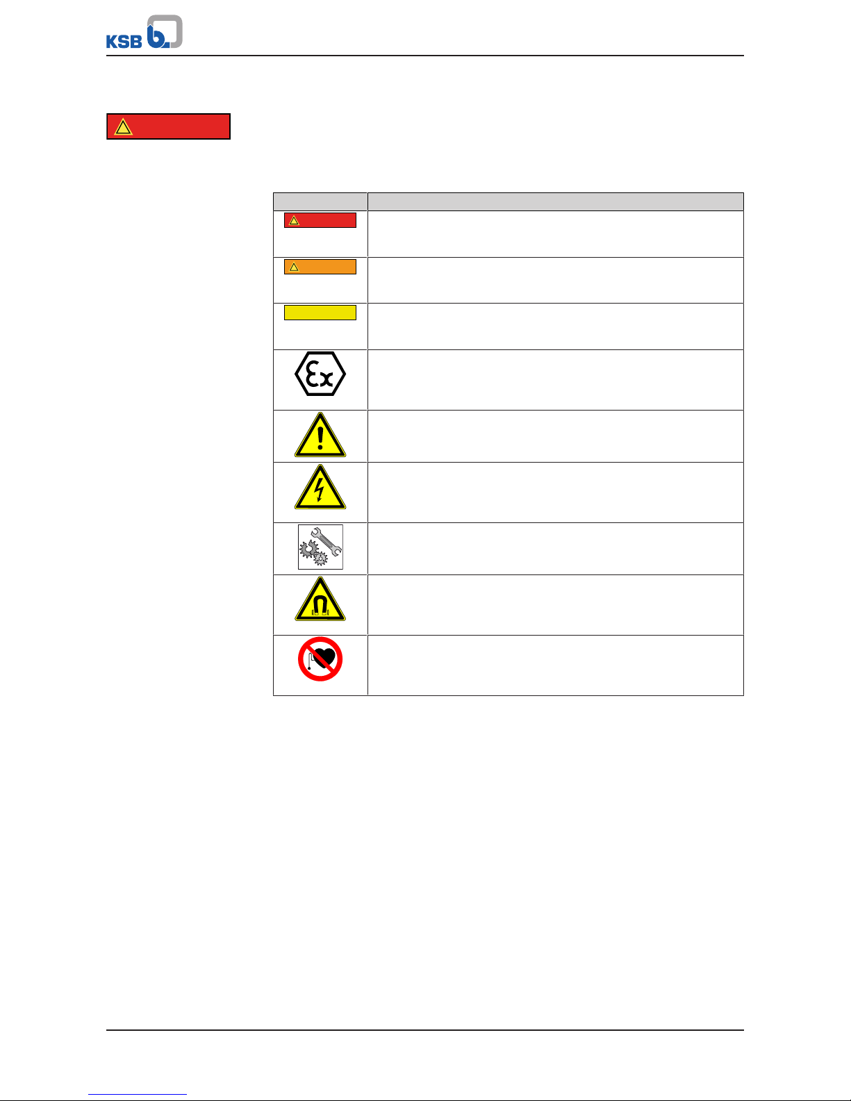
2.1 Key to safety symbols/markings
Table3: Definition of safety symbols/markings
Symbol Description
!
DANGER
DANGER
This signal word indicates a high-risk hazard which, if not avoided,
will result in death or serious injury.
!
WARNING
WARNING
This signal word indicates a medium-risk hazard which, if not
avoided, could result in death or serious injury.
CAUTION
CAUTION
This signal word indicates a hazard which, if not avoided, could
result in damage to the machine and its functions.
Explosion protection
This symbol identifies information about avoiding explosions in
potentially explosive atmospheres in accordance with EU Directive
2014/34/EU (ATEX).
General hazard
In conjunction with one of the signal words this symbol indicates a
hazard which will or could result in death or serious injury.
Electrical hazard
In conjunction with one of the signal words this symbol indicates a
hazard involving electrical voltage and identifies information about
protection against electrical voltage.
Machine damage
In conjunction with the signal word CAUTION this symbol indicates
a hazard for the machine and its functions.
Warning: Strong magnetic field
In conjunction with one of the signal words this symbol indicates a
hazard involving magnetic fields and identifies information about
protection against magnetic fields.
Warning for persons with pacemaker
In conjunction with one of the signal words this symbol indicates a
hazard involving magnetic fields and identifies special information
for persons with a pacemaker.
2.2 General
This manual contains general installation, operating and maintenance instructions
that must be observed to ensure safe pump operation and prevent personal injury
and damage to property.
The safety information in all sections of this manual must be complied with.
This manual must be read and completely understood by the specialist personnel/
operators responsible prior to installation and commissioning.
The contents of this manual must be available to the specialist personnel at the site
at all times.
Information attached directly to the pump must always be complied with and be
kept in a perfectly legible condition at all times. This applies to, for example:
▪ Arrow indicating the direction of rotation
▪ Markings for connections
▪ Name plate
The operator is responsible for ensuring compliance with all local regulations not
taken into account in this manual.
Page 10

2 Safety
10 of 108
Magnochem
2.3 Intended use
▪ The pump (set) must only be operated within the operating limits described in
the other applicable documents.
▪ Only operate pumps/pump sets which are in perfect technical condition.
▪ Do not operate the pump (set) in partially assembled condition.
▪ Only use the pump to handle the fluids described in the data sheet or product
literature of the pump model or variant.
▪ Never operate the pump without the fluid to be handled.
▪ Observe the minimum flow rates indicated in the data sheet or product literature
(to prevent overheating, bearing damage, etc).
▪ Observe the maximum flow rates indicated in the data sheet or product
literature (to prevent overheating, cavitation damage, bearing damage, etc).
▪ Do not throttle the flow rate on the suction side of the pump (to prevent
cavitation damage).
▪ Consult the manufacturer about any use or mode of operation not described in
the data sheet or product literature.
Prevention of foreseeable misuse
▪ Never open the discharge-side shut-off elements further than permitted.
– The maximum flow rates specified in the product literature or data sheet
would be exceeded.
– Risk of cavitation damage
▪ Never exceed the permissible operating limits specified in the data sheet or
product literature regarding pressure, temperature, etc.
▪ Observe all safety information and instructions in this manual.
2.4 Personnel qualification and training
All personnel involved must be fully qualified to transport, install, operate, maintain
and inspect the machinery this manual refers to.
The responsibilities, competence and supervision of all personnel involved in
transport, installation, operation, maintenance and inspection must be clearly
defined by the operator.
Deficits in knowledge must be rectified by means of training and instruction
provided by sufficiently trained specialist personnel. If required, the operator can
commission the manufacturer/supplier to train the personnel.
Training on the pump (set) must always be supervised by technical specialist
personnel.
2.5 Consequences and risks caused by non-compliance with this manual
▪ Non-compliance with this operating manual will lead to forfeiture of warranty
cover and of any and all rights to claims for damages.
▪ Non-compliance can, for example, have the following consequences:
– Hazards to persons due to electrical, thermal, mechanical and chemical
effects and explosions
– Failure of important product functions
– Failure of prescribed maintenance and servicing practices
– Hazard to the environment due to leakage of hazardous substances
Page 11

2 Safety
11 of 108
Magnochem
2.6 Safety awareness
In addition to the safety information contained in this manual and the intended use,
the following safety regulations shall be complied with:
▪ Accident prevention, health and safety regulations
▪ Explosion protection regulations
▪ Safety regulations for handling hazardous substances
▪ Applicable standards, directives and laws
2.7 Safety information for the operator/user
▪ The operator shall fit contact guards for hot, cold and moving parts and check
that the guards function properly.
▪ Do not remove any contact guards during operation.
▪ Provide the personnel with protective equipment and make sure it is used.
▪ Contain leakages (e.g. at the shaft seal) of hazardous fluids handled (e.g.
explosive, toxic, hot) so as to avoid any danger to persons and the environment.
Adhere to all relevant laws.
▪ Eliminate all electrical hazards. (In this respect refer to the applicable national
safety regulations and/or regulations issued by the local energy supply
companies.)
▪ If shutting down the pump does not increase potential risk, fit an emergency-
stop control device in the immediate vicinity of the pump (set) during pump set
installation.
2.8 Safety information for maintenance, inspection and installation
▪ Modifications or alterations of the pump are only permitted with the
manufacturer's prior consent.
▪ Use only original spare parts or parts authorised by the manufacturer. The use of
other parts can invalidate any liability of the manufacturer for resulting damage.
▪ The operator ensures that maintenance, inspection and installation is performed
by authorised, qualified specialist personnel who are thoroughly familiar with
the manual.
▪ Only carry out work on the pump (set) during standstill of the pump.
▪ Any work on the pump set shall only be performed when it has been
disconnected from the power supply (de-energised).
▪ The pump casing must have cooled down to ambient temperature.
▪ Pump pressure must have been released and the pump must have been drained.
▪ When taking the pump set out of service always adhere to the procedure
described in the manual. (ðSection6.1.9,Page46) (ðSection6.3,Page50)
▪ Decontaminate pumps which handle fluids posing a health hazard.
(ðSection7.3,Page59)
▪ As soon as the work has been completed, re-install and/or re-activate any safety-
relevant and protective devices. Before returning the product to service, observe
all instructions on commissioning. (ðSection6.1,Page38)
2.9 Unauthorised modes of operation
Never operate the pump (set) outside the limits stated in the data sheet and in this
manual.
The warranty relating to the operating reliability and safety of the supplied pump
(set) is only valid if the equipment is used in accordance with its intended use.
2.10 Explosion protection
!
DANGER
Always observe the information on explosion protection given in this section when
operating the product in potentially explosive atmospheres.
Page 12

2 Safety
12 of 108
Magnochem
Only pumps/pump sets marked as explosion-proof and identified as such in the data
sheet may be used in potentially explosive atmospheres.
Special conditions apply to the operation of explosion-proof pump sets to EU
Directive 2014/34/EU (ATEX).
Especially adhere to the sections in this manual marked with the Ex symbol and the
following sections, to (ðSection2.10.4,Page13)
The explosion-proof status of the pump set is only assured if the pump set is used in
accordance with its intended use.
Never operate the pump set outside the limits stated in the data sheet and on the
name plate.
Prevent impermissible modes of operation at all times.
2.10.1 Marking
Pump
The marking on the pump refers to the pump part only.
Example of such marking: II 2 G c TX
Refer to the data sheet for the applicable temperature class.
Shaft coupling
An EC manufacturer's declaration is required for the shaft coupling; the shaft
coupling must be marked accordingly.
Motor
The motor must be considered separately.
2.10.2 Temperature limits
In normal pump operation, the highest temperatures are to be expected at the
surface of the pump casing, in the area of the magnetic coupling and in the area of
the rolling element bearings.
The surface temperature at the pump casing corresponds to the temperature of the
fluid handled. If the pump is heated, the operator of the system is responsible for
observing the specified temperature class.
The surfaces in the bearing bracket area must be freely exposed to the atmosphere.
The temperature class specifies the maximum permissible temperature at the surface
of the pump set during operation. For the permissible operating temperature of the
pump in question and the temperature class refer to the data sheet.
If the pump is to be operated at a higher temperature, if there is no data sheet or if
the pump is part of a pool of pumps, contact KSB for the maximum permissible
operating temperature.
2.10.3 Monitoring equipment
The pump (set) must only be operated within the limits specified in the data sheet
and on the name plate.
If the system operator cannot warrant compliance with these operating limits,
appropriate monitoring devices must be used.
Check whether monitoring equipment is required to ensure that the pump set
functions properly.
Take into account the following risks when selecting suitable monitoring equipment:
Cooling flow interrupted
An insufficient cooling flow or failure of the cooling flow can be caused by the
following:
▪ Fluid properties
▪ Pressure or barrier fluid pressure too low
The following malfunctions may occur:
Page 13

2 Safety
13 of 108
Magnochem
Table4: Cooling flow malfunctions
Fault Operating mode
(ðSection4.6,Page22)
Internal
circulation
External
circulation
Low-boiling
fluids
Dead-end
configuration
Blocking of bores within the pump (e.g. casing cover or shaft) ✘ ✘ ✘ ✘
Blocking, clogging, gumming up of the piping (e.g. auxiliary feed lines) - ✘ - ✘
Blocking, clogging, gumming up of the filter (e.g. ring filter, main flow filter) ✘ ✘ ✘ -
Failure or insufficient heat exchanger performance - - - ✘
Failure or insufficient barrier fluid system function - ✘ - ✘
An insufficient cooling flow or failure of the cooling flow may lead to an
impermissible temperature rise.
Inner and outer rotor out of
synchronisation
Overloading, overheating or non-compliance with the design data may cause the
inner and the outer rotor to drop out of synchronisation. Thermal energy produced
inside the containment shroud or at the outer rotor may also result in an
impermissible temperature rise.
Leakage of fluid handled
If a defect in the containment shroud (rare defect) will result in leakage of a fluid
whose critical properties might pose a hazard to staff and the environment, leakage
monitoring must be provided in combination with a pump version with leakage
barrier. Any interaction of the fluid handled with the pump materials shall be taken
into consideration, if necessary.
Accessories available
The following equipment can be supplied by KSB on request:
▪ Temperature monitoring, metal containment shroud
– Pt100 resistance thermometer
– Mineral-insulated thermocouple
▪ Fill level monitoring as dry running protection
– Liquiphant level transmitter
▪ Monitoring for containment shroud leakage
– Liquiphant level transmitter
– Contact pressure gauge
– Pressure switch
– Pressure transducer
▪ Monitoring of pump power to detect dry running and/or asynchronous operation
of the magnetic coupling and to protect against overload operation
– Motor load monitor
▪ Other accessories on request
– Temperature monitoring of rolling element bearings by means of Pt100
resistance thermometer
2.10.4 Operating limits
The minimum flows indicated in (ðSection6.2.3.1,Page48) refer to water and
water-like fluids handled. Longer operating periods with these fluids and at the flow
rates indicated will not cause an additional increase in the temperatures at the pump
surface. However, if the physical properties of the fluids handled are different from
water, it is essential to check whether an additional heat build-up may occur and if
the minimum flow rate must therefore be increased. The calculation formula in
(ðSection6.2.3.1,Page48) can be used to check whether additional heat build-up
may lead to a dangerous temperature increase at the pump surface.
Page 14

2 Safety
14 of 108
Magnochem
2.11 Magnetic coupling
DANGER
Strong magnetic field in the area of the magnetic coupling or the individual
magnets
Danger of death for persons with pacemaker!
Interference with magnetic data carriers, electronic devices, components and
instruments!
Uncontrolled magnetic attraction forces between magnet-equipped components,
tools or similar!
▷ Keep a safety distance of at least 0.3 m.
Distance to assembled pumps:
The safety distance refers to magnet-equipped rotors not yet installed in pumps and
to magnets which have not been fitted.
In installed condition the magnetic field is fully shielded so that an assembled pump
does not pose a hazard as a result of magnetic fields (even to persons with
pacemaker), neither during standstill nor during operation.
Page 15
3 Transport/Temporary Storage/Disposal
15 of 108
Magnochem
3 Transport/Temporary Storage/Disposal
3.1 Checking the condition upon delivery
1. On transfer of goods, check each packaging unit for damage.
2. In the event of in-transit damage, assess the exact damage, document it and
notify KSB or the supplying dealer (as applicable) and the insurer about the
damage in writing immediately.
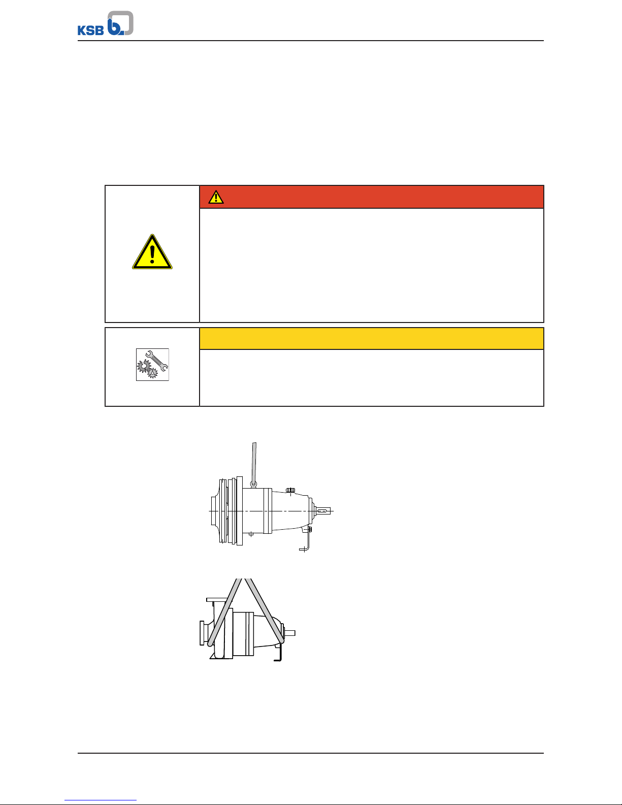
3.2 Transport
DANGER
The pump (set) could slip out of the suspension arrangement
Danger to life from falling parts!
▷ Always transport the pump (set) in the specified position.
▷ Never attach the suspension arrangement to the free shaft end or the motor
eyebolt.
▷ Give due attention to the weight data and the centre of gravity.
▷ Observe the applicable local health and safety regulations.
▷ Use suitable, permitted lifting accessories, e.g. self-tightening lifting tongs.
CAUTION
Improper transport of complete back pull-out unit (with or without impeller)
Damage to the plain bearings!
▷ Use a suitable transport lock to prevent axial movement of the pump shaft
during transport.
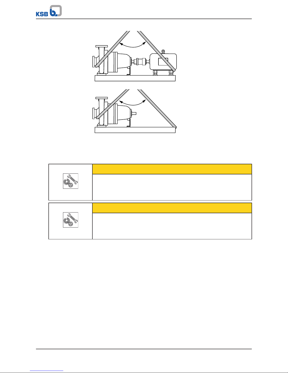
To transport the pump/pump set or back pull-out unit suspend it from the lifting tackle
as shown.
Fig.1: Transporting the back pull-out unit
Fig.2: Transporting the pump
Page 16
3 Transport/Temporary Storage/Disposal
16 of 108
Magnochem
≤ 90 °
Fig.3: Transporting the pump set
≤ 90 °
Fig.4: Transporting the pump on the baseplate
3.3 Storage/preservation
If commissioning is to take place some time after delivery, we recommend that the
following measures be taken for pump (set) storage.
CAUTION
Damage during storage by humidity, dirt, or vermin
Corrosion/contamination of the pump (set)!
▷ For outdoor storage cover the packed or unpacked pump (set) and accessories
with waterproof material.
CAUTION
Wet, contaminated or damaged openings and connections
Leakage or damage to the pump!
▷ Clean and cover pump openings and connections as required prior to putting
the pump into storage.
Store the pump (set) in a dry, protected room where the atmospheric humidity is as
constant as possible.
Rotate the shaft by hand once a month, e.g. via the motor fan.
If properly stored indoors, the pump set is protected for a maximum of 12 months.
New pumps/pump sets are supplied by our factory duly prepared for storage.
For storing a pump (set) which has already been operated, the shutdown measures
must be adhered to. (ðSection6.3.1,Page50)
3.4 Return to supplier
1. Drain the pump as per operating instructions. (ðSection7.3,Page59)
2. Always flush and clean the pump, particularly if it has been used for handling
noxious, explosive, hot or other hazardous fluids.
Page 17
3 Transport/Temporary Storage/Disposal
17 of 108
Magnochem
3. If the pump set has handled fluids whose residues could lead to corrosion
damage in the presence of atmospheric humidity or could ignite upon contact
with oxygen, the pump set must also be neutralised, and anhydrous inert gas
must be blown through the pump to ensure drying.
4. Always complete and enclose a certificate of decontamination when returning
the pump (set).
Always indicate any safety and decontamination measures taken.
(ðSection11,Page105)
NOTE
If required, a blank certificate of decontamination can be downloaded from the
KSB web site at: www.ksb.com/certificate_of_decontamination
3.5 Disposal
WARNING
Fluids, consumables and supplies which are hot and/or pose a health hazard
Hazard to persons and the environment!
▷ Collect and properly dispose of flushing fluid and any residues of the fluid
handled.
▷ Wear safety clothing and a protective mask, if required.
▷ Observe all legal regulations on the disposal of fluids posing a health hazard.
1. Dismantle the pump (set).
Collect greases and other lubricants during dismantling.
2. Separate and sort the pump materials, e.g. by:
- Metals
- Plastics
- Electronic waste
- Greases and other lubricants
3. Dispose of materials in accordance with local regulations or in another controlled
manner.
Page 18
4 Description
18 of 108
Magnochem
4 Description
4.1 General description
▪ Standardised chemical mag-drive pump
Pump for handling aggressive, toxic, explosive, valuable, flammable, malodorous or
harmful fluids in the chemical, petrochemical and general industries.
4.2 Designation
Example: MACD050-032-2501CCHX1A
Table5: Key to the designation
Code Description
MACD Type series (full name: Magnochem)
050 Nominal suction nozzle diameter [mm]
032 Nominal discharge nozzle diameter [mm]
250 Nominal impeller diameter [mm]
1 Hydraulic system, e.g. 1 = low-flow hydraulic system
C Casing material, e.g. C = stainless steel
C Impeller material, e.g. C = stainless steel
H Additional code, e.g. H = heatable casing
X Special design
1 Nominal diameter of magnetic coupling, e.g. 1 = 85mm
A Effective length of magnetic coupling, e.g. A = 10mm
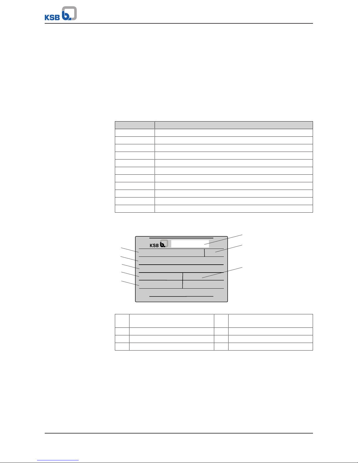
4.3 Name plate
MACD050-032-2501CCHX1A
P-No. 997125086300550001
Q 20 m
3
/h H 25 m
n 2955 1/min
KSB Aktiengesellschaft
67227 Frankenthal
Mat-No. 01 109 223 ZN 3804 - D 52 x 74
2013
0520-5-P-10000-31
1
2
5
4
3
6
7
8
Fig.5: Name plate (example)
1 Type series, size, material, magnetic
coupling size
2 Customer-specific information
(optional)
3 KSB order and order item number 4 Flow rate
5 Speed 6 Manufacturer's name and address
7 Year of construction 8 Head
Page 19

4 Description
19 of 108
Magnochem
4.4 Design details
Design
▪ Volute casing pump
▪ Horizontal installation
▪ Back pull-out design
▪ Single-stage
▪ Meets the technical requirements to ISO 5199
▪ Dimensions and ratings to ISO2858
complemented by pumps of nominal diameters DN25, DN200 and DN250
Pump casing
▪ Single or double volute, depending on the pump size
▪ Radially split volute casing
▪ Volute casing with integrally cast pump feet
▪ Replaceable casing wear rings
▪ Heatable
▪ Draining facility
Impeller type
▪ Closed radial impeller with multiply curved vanes
▪ Discharge-side sealing clearance reduces axial thrust
Shaft seal
▪ Seal-less, with magnetic coupling
▪ Containment shroud as sealing element
▪ Optional: with leakage barrier
Casing cover variants
▪ Internal circulation
▪ Low-boiling fluids
▪ External circulation
– With the fluid handled
– With barrier fluid
▪ Dead-end configuration
In addition:
▪ Flushing connection
▪ Heatable
▪ Draining facility
▪ Internal ring filter or main flow filter
Bearings
Drive-end bearings:
▪ Radial ball bearings with internal clearance C3
▪ Grease-packed for life (high melting point grease)
▪ Optional: oil lubrication
Pump-end bearing:
▪ Hydrodynamic plain bearings
▪ Product-lubricated
2) Shaft seal ring, up to PN16 max.
Page 20
4 Description
20 of 108
Magnochem
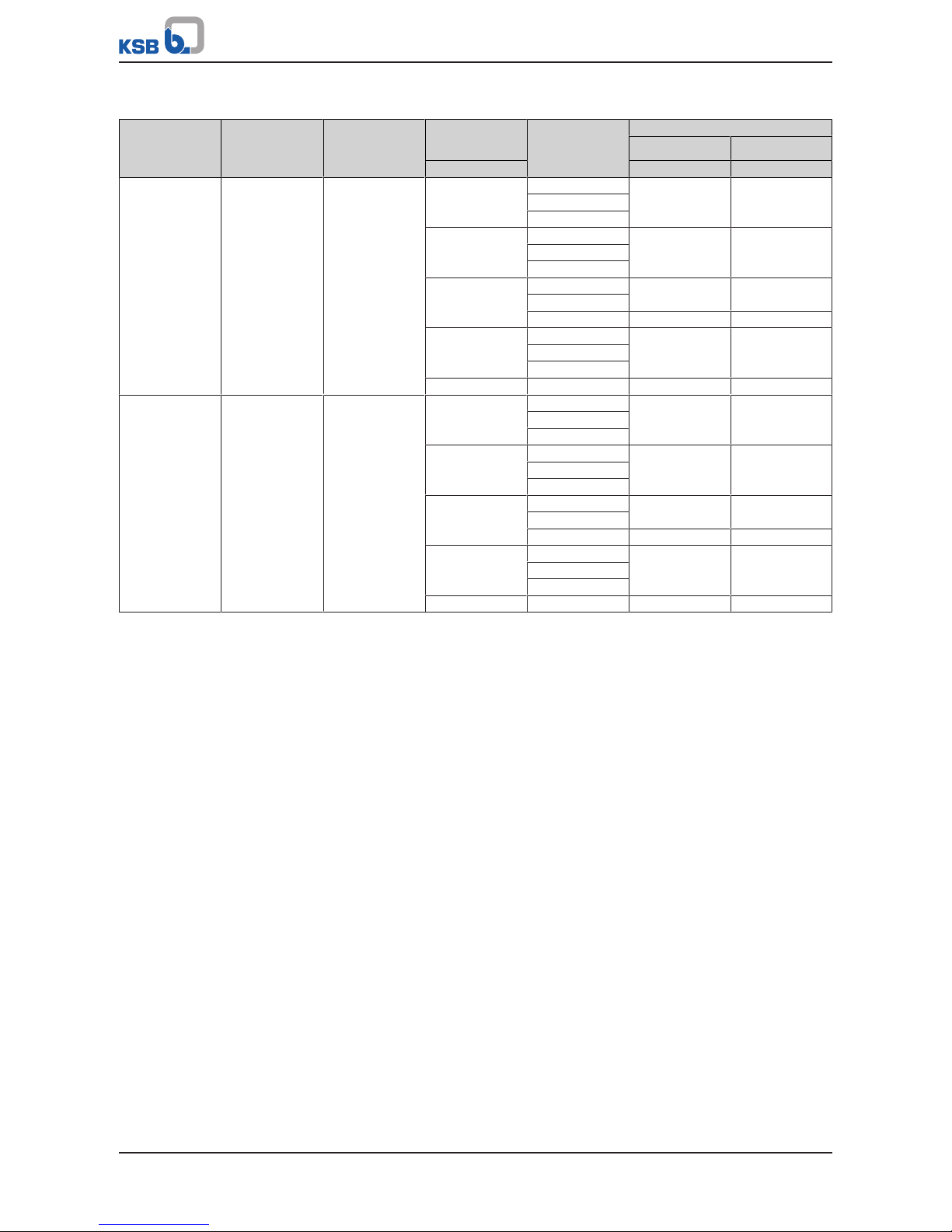
Table6: Bearings used
Type of lubrication Pump nominal
pressure
Leakage barrier
model
Nominal diameter
of magnetic
coupling
Bearing bracket Rolling element bearings
Pump end Drive end
[mm] 321.01 321.02
Grease-lubricated PN16/25/40 Not available or
shaft seal ring
2)
85 CS40 6209 ZZN C3 6209 ZZN C3
CS50
CS60
123 CS40 6209 ZZN C3 6209 ZZN C3
CS50
CS60
172 CS50 6209 ZZN C3 6209 ZZN C3
CS60
CS80 6212 ZZN C3 6212 ZZN C3
235 CS50 6212 ZZN C3 6212 ZZN C3
CS60
CS80
265 CS80 6212 ZZN C3 6212 ZZN C3
Oil-lubricated PN16/25/40 Not available or
shaft seal ring
2)
85 CS40 6209 NZ C3 6209 NZ C3
CS50
CS60
123 CS40 6209 NZ C3 6209 NZ C3
CS50
CS60
172 CS50 6209 NZ C3 6209 NZ C3
CS60
CS80 6212 NZ C3 6212 NZ C3
235 CS50 6212 NZ C3 6212 NZ C3
CS60
CS80
265 CS80 6212 NZ C3 6212 NZ C3
Automation
Automation options:
▪ PumpDrive
▪ PumpMeter
Page 21
4 Description
21 of 108
Magnochem
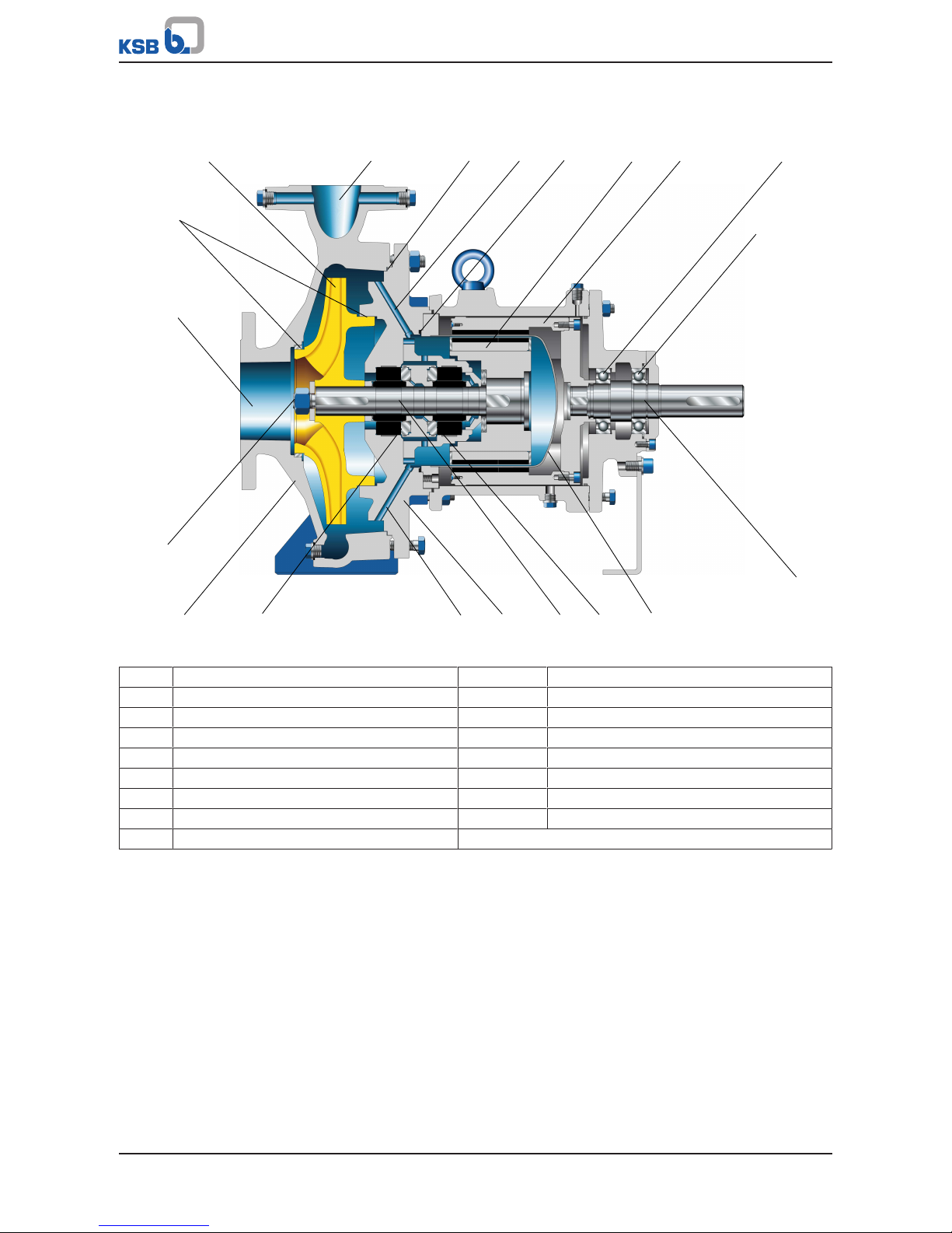
4.5 Configuration and function
1 2 3 4 5
6 7
8
9
10
1112
13
14
15
16
18
17
20
19
Fig.6: Sectional drawing
1 Impeller 2 Discharge nozzle
3 Casing gasket 4,15 Circulation bore
5 Shroud gasket 6 Inner rotor
7 Outer rotor 8, 9 Rolling element bearings
10 Drive-end shaft 11, 16 Hydrodynamic plain bearings
12 Pump-end shaft 13 Containment shroud
14 Casing cover 17 Pump casing
18 Shaft bore 19 Suction nozzle
20 Clearance gap
Function
The fluid enters the pump axially via the suction nozzle (19) and is accelerated
outward by the rotating impeller (1). In the flow passage of the pump casing the
kinetic energy of the fluid is converted into pressure energy. The fluid is pumped to
the discharge nozzle (2), where it leaves the pump. The clearance gap (20) prevents
any fluid from flowing back from the casing to the suction nozzle.
Sealing
Mag-drive pumps are characterised by the absence of a dynamic shaft seal
(mechanical seal, gland packing). The fluid handled is sealed to atmosphere
exclusively by means of static sealing elements: a gasket (3) between the casing (17)
and the casing cover (14), and a joint ring (5) between the casing cover (14) and the
containment shroud (13). The driving torque is transmitted indirectly from the motor
to the pump shaft (12) via the magnetic coupling. The magnetic coupling basically
consists of the outer rotor (outer magnet assembly, 7) and the inner rotor (inner
magnet assembly, 6). The containment shroud (13) forms the shaft seal separating
the wetted from the dry pump section.
Magnetic coupling
Magnetic couplings with permanent magnets transmit the driving torque without
slip, i.e. the motor and the pump run at the same rotational speed. The driving
torque generated by the motor is transmitted from the outer rotor (7) to the inner
Page 22
4 Description
22 of 108
Magnochem
rotor (6) via the magnetic field. It is part of the inner rotor assembly which runs in
product-lubricated bearings. The directly product-lubricated radial and axial plain
bearings (11, 16) are made of wear-resistant and chemically resistant silicon carbide.
The flow circulated through the magnetic coupling not only lubricates the bearings
but also dissipates heat losses caused by eddy currents in the metal containment
shroud wall. If a ceramic containment shroud is used, no eddy current losses will be
induced in the containment shroud wall. (ðSection4.6,Page22)
4.6 Operating modes
The operating mode defines the route the cooling and lubricating flow takes
through the magnetic coupling. Depending on the operating mode, the cooling and
lubricating flow is routed differently through the magnetic coupling. A distinction is
made between the following operating modes:
▪ Operating mode: internal circulation
In internal circulation operating mode, the fluid handled is used to lubricate the
plain bearings and to dissipate the heat generated by the magnetic coupling. The
difference in pressure results in a lubricating and cooling flow from the suction
to the pressure side. The fluid flows through bores provided in the casing cover
on the pressure side and returns to the suction side through an axial shaft bore.
▪ Operating mode: external circulation
In external circulation operating mode, the fluid used to lubricate the plain
bearings and to dissipate the heat generated by the magnetic coupling is fed
into the pump from outside (either from the discharge nozzle with or without a
main flow filter, or from an external fluid supply in the plant). Either the fluid
handled or another fluid can be used. With the external circulation variant, the
lubricating and cooling flow is fed into the pump via auxiliary connections at the
casing cover and flows back to the suction side via an axial shaft bore.
▪ Operating mode: low-boiling fluids
In low-boiling fluids operating mode, the fluid handled is used to lubricate the
plain bearings and to dissipate the heat generated by the magnetic coupling. The
lubricating and cooling flow is ensured by an integrated auxiliary impeller. The
fluid flows through bores provided in the casing cover on the pressure side and is
returned to the pressure side through bores in the casing cover. This operating
mode is particularly suitable for fluids which have a steep vapour pressure curve.
▪ Operating mode: dead end configuration
In dead-end configuration operating mode, either the fluid handled or an
external fluid is used to lubricate the plain bearings and to dissipate the heat
generated by the magnetic coupling. The lubricating and cooling flow is ensured
by an integrated auxiliary impeller in an almost closed circuit between the
magnetic coupling and a heat exchanger; the latter ensures that the heat
generated by the magnetic coupling is dissipated. The liquid flows into and out
of the pump via auxiliary connections at the casing cover. If pressurised barrier
fluid is used, a flow from the magnetic coupling to the main impeller is possible
but a return flow back to the magnetic coupling prevented.
4.7 Noise characteristics
Table7: Surface sound pressure level L
pA
3)4)
P
N
Pump Pump set
960rpm,
760rpm
1450rpm 2900rpm 960rpm,
760rpm
1450rpm 2900rpm
[kW] [dB] [dB] [dB] [dB] [dB] [dB]
1,5 52 53 54 56 58 63
2,2 53 55 56 58 60 66
3 55 56 57 60 62 68
4 56 58 59 61 63 69
3) Spatial average; as per ISO3744 and EN12639; valid for pump operation in the Q/Qopt = 0.8-1.1 range and for non-
cavitating operation. If noise levels are to be guaranteed: add +3dB for measuring and constructional tolerance.
4) Increase for 60Hz operation: 3500rpm +3dB, 1750rpm +1dB, 1160rpm ±0dB
Page 23

4 Description
23 of 108
Magnochem
P
N
Pump Pump set
960rpm,
760rpm
1450rpm 2900rpm 960rpm,
760rpm
1450rpm 2900rpm
[kW] [dB] [dB] [dB] [dB] [dB] [dB]
5,5 58 59 61 62 65 71
7,5 59 61 62 64 66 72
11 61 63 64 65 68 74
15 63 65 66 67 69 75
18,5 64 66 67 68 70 76
22 65 67 68 68 71 77
30 66 68 70 70 72 78
37 67 70 71 70 73 79
45 68 71 72 71 74 80
55 69 72 73 72 74 80
75 71 73 75 73 76 81
90 71 74 76 73 76 82
110 72 75 77 74 77 82
132 73 76 78 75 77 83
160 74 77 79 75 78 84
200 75 78 80 76 79 84
250 - 79 81 - 80 85
4.8 Scope of supply
Depending on the model, the following items are included in the scope of supply:
▪ Pump
▪ KSB surface-cooled IEC frame three-phase current squirrel-cage motor
▪ Flexible coupling with or without spacer
▪ Coupling guard
▪ Baseplate (to ISO 3661), cast or welded, for pump and motor, in torsion-resistant
design
4.9 Dimensions and weights
For dimensions and weights please refer to the general arrangement drawing/outline
drawing of the pump/pump set.
Page 24
5 Installation at Site
24 of 108
Magnochem
5 Installation at Site
5.1 Safety regulations
DANGER
Improper installation in potentially explosive atmospheres
Explosion hazard!
Damage to the pump set!
▷ Comply with the applicable local explosion protection regulations.
▷ Observe the information in the data sheet and on the name plates of pump and
motor.
DANGER
Strong magnetic field in the area of the magnetic coupling or the individual
magnets
Danger of death for persons with pacemaker!
Interference with magnetic data carriers, electronic devices, components and
instruments!
Uncontrolled magnetic attraction forces between magnet-equipped components,
tools or similar!
▷ Keep a safety distance of at least 0.3 m.
▷ Also observe the additional instructions. (ðSection2.11,Page14)
5.2 Checks to be carried out prior to installation
Place of installation
WARNING
Installation on mounting surface which is unsecured and cannot support the load
Personal injury and damage to property!
▷ Use a concrete of compressive strength class C12/15 which meets the
requirements of exposure class XC1 to EN206-1.
▷ The mounting surface must have set and must be completely horizontal and
even.
▷ Observe the weights indicated.
1. Check the structural requirements.
All structural work required must have been prepared in accordance with the
dimensions stated in the outline drawing/general arrangement drawing.
5.3 Installing the pump set
DANGER
Excessive temperatures due to improper installation
Explosion hazard!
▷ Install the pump in a horizontal position to ensure self-venting of the pump.
▷ In external circulation and dead-end configuration operating modes, vent the
rotor space separately via the auxiliary connections at the casing cover.
Page 25
5 Installation at Site
25 of 108
Magnochem
DANGER
Improper installation
Excessive temperature of oil-lubricated rolling element bearings!
▷ Always install the pump set horizontally and align it.
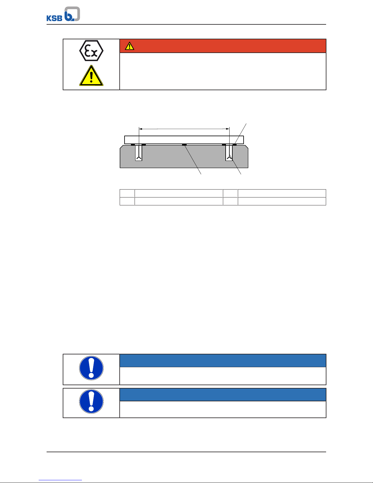
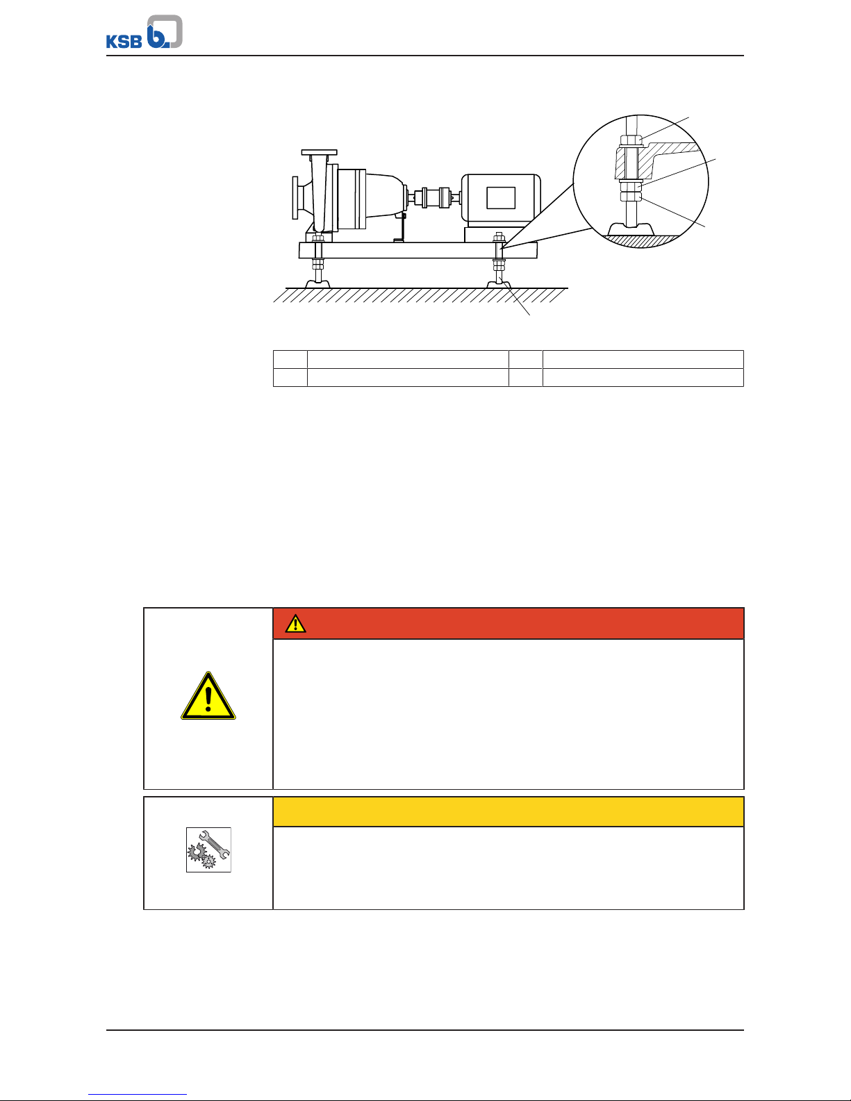
5.3.1 Installation on the foundation
L
1
32
Fig.7: Fitting the shims
L Bolt-to-bolt distance 1 Shim
2 Shim if (L) > 800 mm 3 Foundation bolt
ü The foundation has the required strength and characteristics.
ü The foundation has been prepared in accordance with the dimensions given in
the outline drawing/general arrangement drawing.
1. Position the pump set on the foundation and level it with the help of a spirit
level placed on the shaft and discharge nozzle.
Permissible deviation: 0.2 mm/m.
2. Use shims (1) for height compensation, if necessary.
Always fit shims, if any, immediately to the left and right of the foundation bolts
(3) between the baseplate/foundation frame and the foundation.
For a bolt-to-bolt distance (L) > 800mm fit additional shims (2) halfway between
the bolt holes.
All shims must lie perfectly flush.
3. Insert the foundation bolts (3) into the holes provided.
4. Use concrete to set the foundation bolts (3) into the foundation.
5. Wait until the concrete has set firmly, then level the baseplate.
6. Tighten the foundation bolts (3) evenly and firmly.
7. Grout the baseplate using low-shrinkage concrete with a standard particle size
and a water/cement ratio of ≤ 0.5.
Produce flowability with the help of a solvent.
Perform secondary treatment of the concrete to DIN 1045.
NOTE
For low-noise operation contact the manufacturer to check whether the pump set
can be installed on anti-vibration mounts.
NOTE
Expansion joints can be fitted between the pump and the suction/discharge line.
Page 26
5 Installation at Site
26 of 108
Magnochem
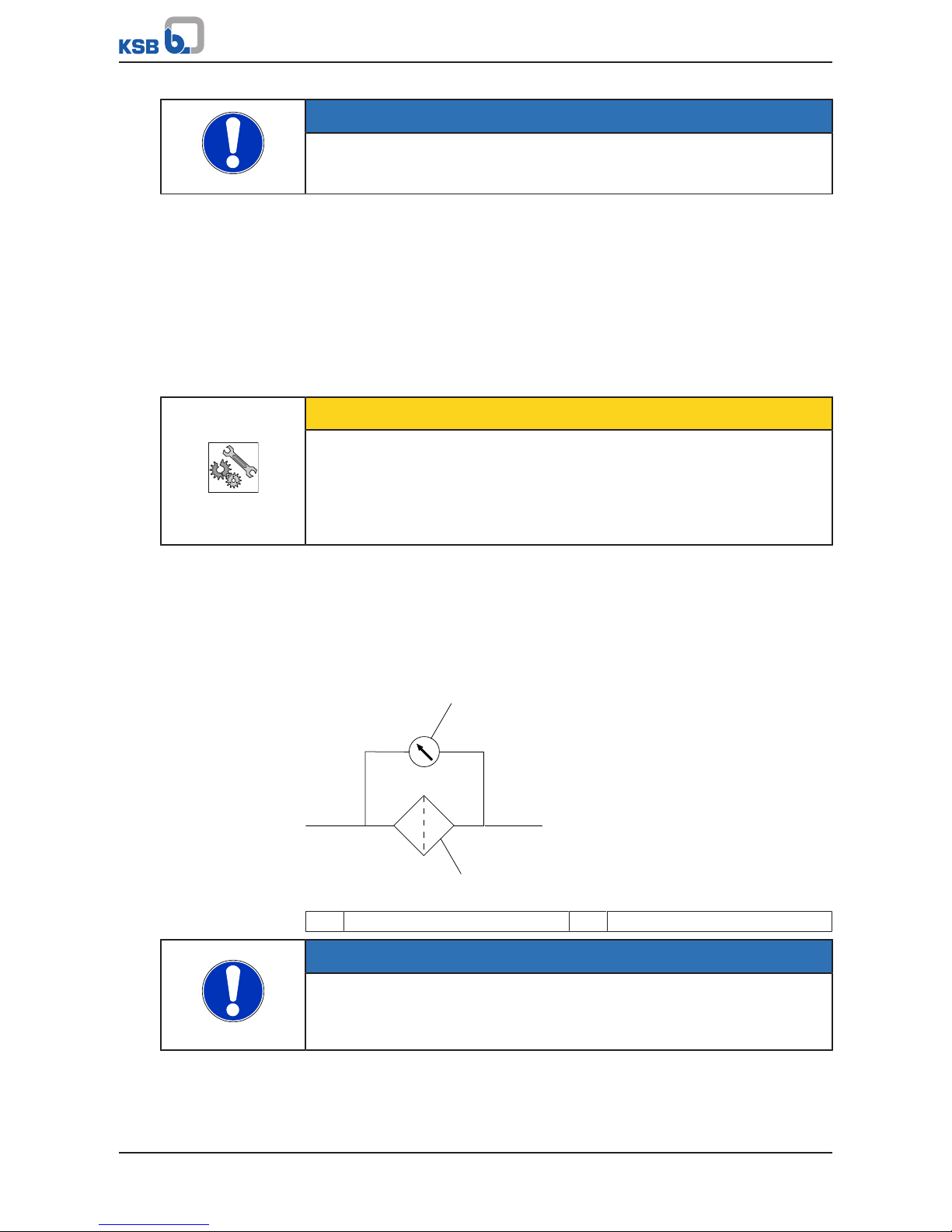
5.3.2 Installation without foundation
4
1
2
3
Fig.8: Adjusting the levelling elements
1, 3 Locknut 2 Adjusting nut
4 Machine mount
ü The installation surface has the required strength and characteristics.
1. Position the pump set on the machine mounts (4) and align it with the help of a
spirit level (on the shaft/discharge nozzle).
2. To adjust any differences in height, loosen the bolts and locknuts (1, 3) of the
machine mounts (4).
3. Turn the adjusting nut (2) until any differences in height have been
compensated.
4. Re-tighten the locknuts (1, 3) at the machine mounts (4).
5.4 Piping
5.4.1 Connecting the piping
DANGER
Impermissible loads acting on the pump nozzles
Danger to life from leakage of hot, toxic, corrosive or flammable fluids!
▷ Do not use the pump as an anchorage point for the piping.
▷ Anchor the pipes in close proximity to the pump and connect them without
transmitting any stresses or strains.
▷ Observe the permissible forces and moments at the pump nozzles.
(ðSection5.4.2,Page28)
▷ Take appropriate measures to compensate for thermal expansion of the piping.
CAUTION
Incorrect earthing during welding work at the piping
Destruction of rolling element bearings (pitting effect)!
▷ Never earth the electric welding equipment on the pump or baseplate.
▷ Prevent current flowing through the rolling element bearings.
Page 27
5 Installation at Site
27 of 108
Magnochem
NOTE
Installing check and shut-off elements in the system is recommended, depending on
the type of plant and pump. However, such elements must not obstruct proper
drainage or hinder disassembly of the pump.
ü Suction lift lines have been laid with a rising slope, suction head lines with a
downward slope towards the pump.
ü A flow stabilisation section having a length equivalent to at least twice the
diameter of the suction flange has been provided upstream of the suction flange.
ü The nominal diameters of the pipelines are at least equal to the nominal
diameters of the pump nozzles.
ü Adapters to larger diameters have a diffuser angle of approximately 8° to
prevent excessive pressure losses.
ü The pipelines have been anchored in close proximity to the pump and connected
without transmitting any stresses or strains.
CAUTION
Welding beads, scale and other impurities in the piping
Damage to the pump!
▷ Free the piping from any impurities.
▷ If necessary, install a filter.
▷ Comply with the instructions set out in (ðSection7.2.2.3,Page55) .
1. Thoroughly clean, flush and blow through all vessels, pipelines and connections
(especially of new installations).
2. Before installing the pump in the piping, remove the flange covers on the suction
and discharge nozzles of the pump.
3. Check that the inside of the pump is free from any foreign objects. Remove any
foreign objects.
4. If required, install a filter in the piping (see figure: Filter in the piping).
1
2
Fig.9: Filter in the piping
1 Differential pressure gauge 2 Filter
NOTE
Use a filter with laid-in wire mesh of 0.5 mm x 0.25 mm (mesh size x wire diameter)
made of corrosion-resistant material.
Use a filter with a filter area three times the cross-section of the piping.
Conical filters have proved suitable.
5. Connect the pump nozzles to the piping.
Page 28
5 Installation at Site
28 of 108
Magnochem
CAUTION
Aggressive flushing and pickling agents
Damage to the pump!
▷ Match the cleaning operation mode and duration for flushing and pickling
service to the casing and seal materials used.
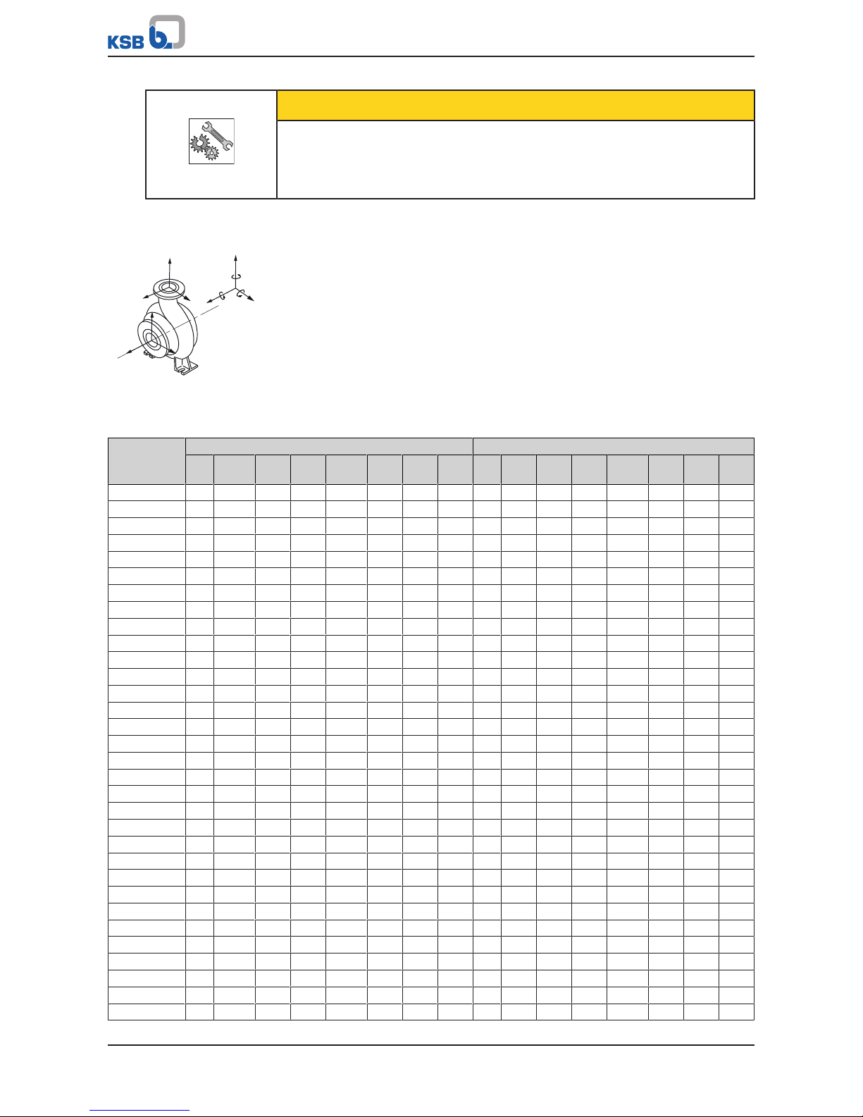
5.4.2 Permissible forces and moments at the pump nozzles
[+]
F
z
F
y
F
x
F
x
F
y
F
z
F
x
F
y
F
z
M
z
M
y
M
x
Fig.10: Forces and moments at
the pump nozzles
The data on forces and moments apply to static piping loads only. If the limits are
exceeded, they must be checked and verified.
If a computerised strength analysis is required, values are available on request only.
The values are only applicable if the pump is installed on a completely grouted
baseplate and bolted to a rigid and level foundation.
Table8: Forces and moments at the pump nozzles for material variant C (1.4408/A743GRCF8M) at 20°C.
Size Suction nozzle Discharge nozzle
DN F
x
[N]
F
y
[N]
F
z
[N]
∑
F
[N]
M
x
[Nm]
M
y
[Nm]
M
z
[Nm]
DN F
x
[N]
F
y
[N]
F
z
[N]
∑
F
[N]
M
x
[Nm]
M
y
[Nm]
M
z
[Nm]
040-025-160 40 970 780 650 1404 845 585 683 25 490 455 600 898 370 390 455
040-025-200 40 970 780 650 1404 845 585 683 25 460 455 600 898 370 390 455
050-032-125 50 1240 1010 878 1824 910 650 748 32 650 555 780 1157 715 490 555
050-032-125.1 50 1240 1010 878 1824 910 650 748 32 650 555 780 1157 715 490 555
050-032-160 50 1240 1010 878 1824 910 650 748 32 650 555 780 1157 715 490 555
050-032-160.1 50 1240 1010 878 1824 910 650 748 32 650 555 780 1157 715 490 555
050-032-200 50 1240 1010 878 1824 910 650 748 32 650 555 780 1157 715 490 555
050-032-200.1 50 1240 1010 878 1824 910 650 748 32 650 555 780 1157 715 490 555
050-032-250 50 1240 1010 878 1824 910 650 748 32 650 555 780 1157 715 490 555
050-032-250.1 50 1240 1010 878 1824 910 650 748 32 650 555 780 1157 715 490 555
065-040-125 65 1600 1300 1105 2339 1050 715 780 40 780 650 1000 1425 845 585 685
065-040-160 65 1600 1300 1105 2339 1050 715 780 40 780 650 1000 1425 845 585 685
065-040-160.1 65 1600 1300 1105 2339 1050 715 780 40 780 650 1000 1425 845 585 685
065-040-200 65 1600 1300 1105 2339 1050 715 780 40 780 650 1000 1425 845 585 685
065-040-200.1 65 1600 1300 1105 2339 1050 715 780 40 780 650 1000 1425 845 585 685
065-040-250 65 1600 1300 1105 2339 1050 715 780 40 780 650 1000 1425 845 585 685
065-040-250.1 65 1600 1300 1105 2339 1050 715 780 40 780 650 1000 1425 845 585 685
065-040-315 65 1600 1300 1105 2339 1050 715 780 40 780 650 1000 1425 845 585 685
080-050-125 80 2000 1550 1333 2860 1330 748 1010 50 1000 880 1250 1827 910 650 750
080-050-160 80 2000 1550 1333 2860 1330 748 1010 50 1000 880 1250 1827 910 650 750
080-050-160.1 80 2000 1550 1333 2860 1330 748 1010 50 1000 880 1250 1827 910 650 750
080-050-200 80 2000 1550 1333 2860 1330 748 1010 50 1000 880 1250 1827 910 650 750
080-050-200.1 80 2000 1550 1333 2860 1330 748 1010 50 1000 880 1250 1827 910 650 750
080-050-250 80 2000 1550 1333 2860 1330 748 1010 50 1000 880 1250 1827 910 650 750
080-050-250.1 80 2000 1550 1333 2860 1330 748 1010 50 1000 880 1250 1827 910 650 750
080-050-315 80 2000 1550 1333 2860 1330 748 1010 50 1000 880 1250 1827 910 650 750
080-050-315.1 80 2000 1550 1333 2860 1330 748 1010 50 1000 880 1250 1827 910 650 750
100-065-125 100 2500 1950 1755 3624 1850 900 1400 65 1300 1105 1600 2339 1050 715 790
100-065-160 100 2500 1950 1755 3624 1850 900 1400 65 1300 1105 1600 2339 1050 715 790
100-065-200 100 2500 1950 1755 3624 1850 900 1400 65 1300 1105 1600 2339 1050 715 790
100-065-250 100 2500 1950 1755 3624 1850 900 1400 65 1300 1105 1600 2339 1050 715 790
100-065-315 100 2500 1950 1755 3624 1850 900 1400 65 1300 1105 1600 2339 1050 715 790
Page 29
5 Installation at Site
29 of 108
Magnochem
Size Suction nozzle Discharge nozzle
DN F
x
[N]
F
y
[N]
F
z
[N]
∑
F
[N]
M
x
[Nm]
M
y
[Nm]
M
z
[Nm]
DN F
x
[N]
F
y
[N]
F
z
[N]
∑
F
[N]
M
x
[Nm]
M
y
[Nm]
M
z
[Nm]
125-080-160 125 3400 2700 2200 4867 2550 1250 1950 80 1550 1335 1950 2826 1350 750 1000
125-080-200 125 3400 2700 2200 4867 2550 1250 1950 80 1550 1335 1950 2826 1350 750 1000
125-080-200.1 125 3400 2700 2200 4867 2550 1250 1950 80 1550 1335 1950 2826 1350 750 1000
125-080-250 125 3400 2700 2200 4867 2550 1250 1950 80 1550 1335 1950 2826 1350 750 1000
125-080-315 125 3400 2700 2200 4867 2550 1250 1950 80 1550 1335 1950 2826 1350 750 1000
125-080-400 125 3400 2700 2200 4867 2550 1250 1950 80 1550 1335 1950 2826 1350 750 1000
125-100-160 125 3400 2700 2200 4867 2550 1250 1950 100 2000 1755 2500 3651 1850 900 1400
125-100-200 125 3400 2700 2200 4867 2550 1250 1950 100 2000 1755 2500 3651 1850 900 1400
125-100-250 125 3400 2700 2200 4867 2550 1250 1950 100 2000 1755 2500 3651 1850 900 1400
125-100-315 125 3400 2700 2200 4867 2550 1250 1950 100 2000 1755 2500 3651 1850 900 1400
125-100-400 125 3400 2700 2200 4867 2550 1250 1950 100 2000 1755 2500 3651 1850 900 1400
150-125-200 150 4300 3450 2850 6206 3200 1600 2450 125 2700 2200 3400 4867 2550 1300 1900
150-125-250 150 4300 3450 2850 6206 3200 1600 2450 125 2700 2200 3400 4867 2550 1300 1900
150-125-315 150 4300 3450 2850 6206 3200 1600 2450 125 2700 2200 3400 4867 2550 1300 1900
150-125-400 150 4300 3450 2850 6206 3200 1600 2450 125 2700 2200 3400 4867 2550 1300 1900
200-150-200 200 6750 5250 4300 9572 4850 2450 3550 150 3450 2850 4300 6206 3150 1600 2450
200-150-250 200 6750 5250 4300 9572 4850 2450 3550 150 3450 2850 4300 6206 3150 1600 2450
200-150-315 200 6750 5250 4300 9572 4850 2450 3550 150 3450 2850 4300 6206 3150 1600 2450
200-150-400 200 6750 5250 4300 9572 4850 2450 3550 150 3450 2850 4300 6206 3150 1600 2450
200-150-500 200 6750 5250 4300 9572 4850 2450 3550 150 3450 2850 4300 6206 3150 1600 2450
200-200-250 200 6750 5250 4300 9572 4850 2450 3550 200 5250 4300 6750 9572 4850 2450 3550
250-200-315 250 9200 7350 6150 13285 6900 3350 5250 200 5250 4300 6750 9572 4850 2450 3550
250-200-400 250 9200 7350 6150 13285 6900 3350 5250 200 5250 4300 6750 9572 4850 2450 3550
250-200-500 250 9200 7350 6150 13285 6900 3350 5250 200 5250 4300 6750 9572 4850 2450 3550
300-250-315 300 11000 9200 7350 16114 8400 4150 6350 250 7350 6150 9150 13250 6900 3350 5250
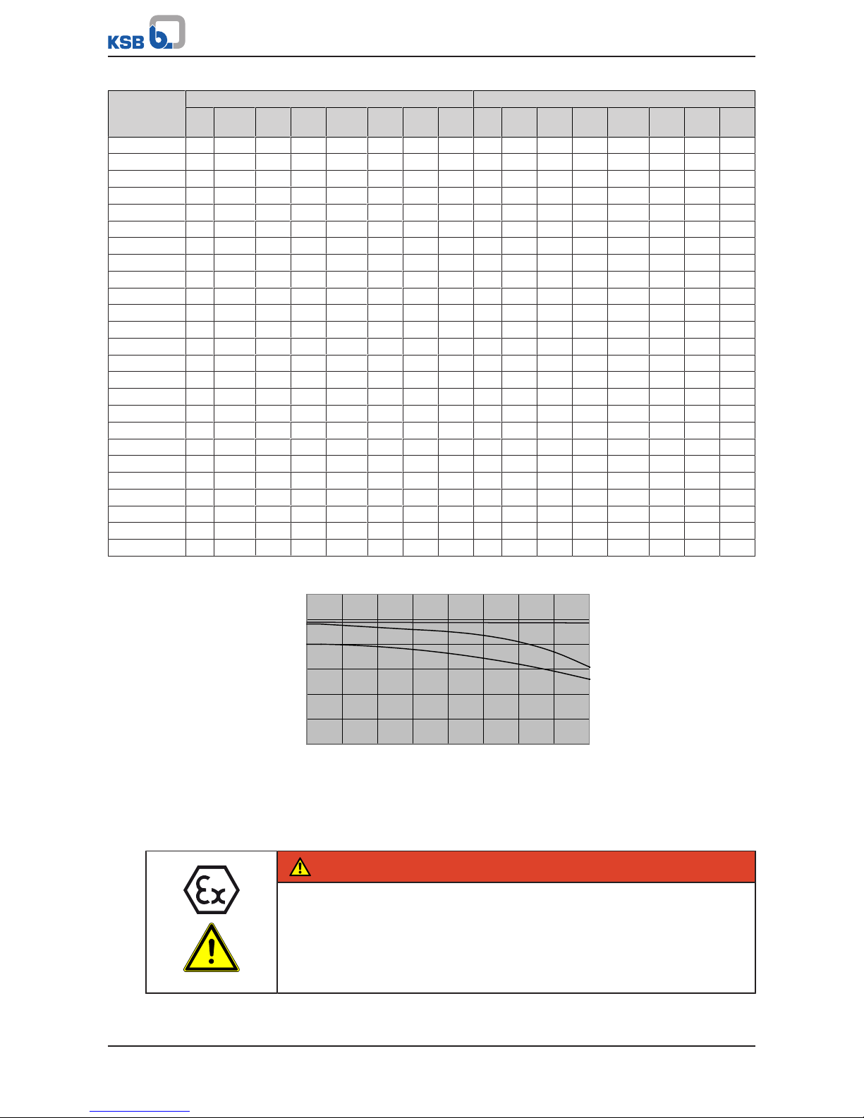
C, V
E, D
Y
0,6
0,7
0,8
0,9
1
1,2
0
50 100 150 200 250 300 400
°C
350
1,1
Correction coefficient
Fig.11: Temperature correction diagram for "C, D, E, V or Y variants" (1.4408/
A743GRCF8M)
5.4.3 Auxiliary connections
DANGER
Risk of potentially explosive atmosphere by mixing of incompatible fluids in the
auxiliary piping
Risk of burns!
Explosion hazard!
▷ Make sure that the barrier fluid and quench liquid are compatible with the
fluid pumped.
Page 30
5 Installation at Site
30 of 108
Magnochem
WARNING
Failure to use or incorrect use of auxiliary connections (e.g. barrier fluid, flushing
liquid, etc.)
Risk of injury from escaping fluid!
Risk of burns!
Malfunction of the pump!
▷ Refer to the general arrangement drawing, the piping layout and pump
markings (if any) for the quantity, dimensions and locations of auxiliary
connections.
▷ Use the auxiliary connections provided.
5.5 Enclosure/insulation
DANGER
Impermissible temperature rise resulting from insulation of bearing bracket
lantern
Explosion hazard!
Risk of burns!
▷ If bearing bracket is insulated, monitor the containment shroud temperature.
WARNING
The volute casing and casing/discharge cover take on the same temperature as
the fluid handled
Risk of burns!
▷ Insulate the volute casing.
▷ Fit protective equipment.
CAUTION
Heat build-up in the bearing bracket
Damage to the bearings!
▷ Bearing brackets must not be insulated.
▷ The bearing temperature must not exceed 90 °C (measured on the outside of
the bearing bracket).
Page 31

5 Installation at Site
31 of 108
Magnochem
102 161
344 330
Fig.12: Area where insulation is permitted
102 Volute casing 161 Casing cover
344 Bearing bracket lantern 330 Bearing bracket
Area where insulation is permitted
5)
NOTE
Monitoring systems can be connected to casing cover 161 and bearing bracket
lantern 344. When insulating the casing cover and bearing bracket lantern make
sure that the sensor connections and displays remain accessible. Also observe the
sensor manufacturer's specifications regarding the permissible ambient
temperature.
5.6 Checking the coupling alignment
DANGER
Inadmissible temperatures at the coupling or bearings due to misalignment of the
coupling
Explosion hazard!
Risk of burns!
▷ Make sure that the coupling is correctly aligned at all times.
CAUTION
Misalignment of pump and motor shafts
Damage to pump, motor and coupling!
▷ Always check the coupling after the pump has been installed and connected to
the piping.
▷ Also check the coupling of pump sets supplied with pump and motor mounted
on the same baseplate.
5) Identifies components where insulation is permitted but does not indicate a specific insulation type or design.
Page 32

5 Installation at Site
32 of 108
Magnochem
B
A
A
B
a) b)
B
B
A
A
1
1
2
21
1
Fig.13: Checking the coupling alignment: Coupling without spacer sleeve (a) or Coupling with spacer sleeve (b)
1 Straight-edge 2 Gauge
ü The coupling guard and its footboard, if any, have been removed.
1. Loosen the support foot and re-tighten it without transmitting any stresses and
strains.
2. Place the straight-edge axially on both coupling halves.
3. Leave the straight-edge in this position and turn the coupling by hand.
The coupling is aligned correctly if the distances A and B to the respective shafts
are the same at all points around the circumference.
The radial and axial deviation between the two coupling halves must not exceed
0.1 mm, during standstill as well as at operating temperature and under inlet
pressure.
4. Check the distance (dimension see general arrangement drawing) between the
two coupling halves around the circumference.
The coupling is correctly aligned if the distance between the two coupling halves
is the same at all points around the circumference.
The radial and axial deviation between the two coupling halves must not exceed
0.1 mm, during standstill as well as at operating temperature and under inlet
pressure.
5. If alignment is correct, re-install the coupling guard and its footboard, if any.
5.7 Aligning the pump and motor
After having installed the pump set and connected the piping, check the coupling
alignment and, if required, re-align the pump set (at the motor).
Page 33

5 Installation at Site
33 of 108
Magnochem
5.7.1 Motors with adjusting screw
1
3
2
Fig.14: Motor with adjusting screw
1 Hexagon head bolt 2 Adjusting screw
3 Locknut
ü The coupling guard and its footboard, if any, have been removed.
1. Check the coupling alignment.
2. Unscrew the hexagon head bolts (1) at the motor and the locknuts (3) at the
baseplate.
3. Turn the adjusting screws (2) by hand or by means of an open-end wrench until
the coupling alignment is correct and all motor feet rest squarely on the
baseplate.
4. Re-tighten the hexagon head bolts (1) at the motor and the locknuts (3) at the
baseplate.
5. Check proper functioning of coupling/shaft.
Check that coupling/shaft can easily be rotated by hand.
WARNING
Unprotected rotating coupling
Risk of injury by rotating shafts!
▷ Always operate the pump set with a coupling guard.
If the customer specifically requests not to include a coupling guard in KSB's
delivery, then the operator must supply one!
▷ Observe all relevant regulations for selecting a coupling guard.
DANGER
Risk of ignition by frictional sparks
Explosion hazard!
▷ Choose a coupling guard material that is non-sparking in the event of
mechanical contact (see DIN EN 13463-1).
6. Fit the coupling guard and its footboard, if any.
7. Check the distance between coupling and coupling guard.
The coupling guard must not touch the coupling.
5.7.2 Motors without adjusting screw
Any differences in the centreline heights of the pump and motor shafts are
compensated by means of shims.
Page 34

5 Installation at Site
34 of 108
Magnochem
1
Fig.15: Pump set with shim
1 Shim
ü The coupling guard and its footboard, if any, have been removed.
1. Check the coupling alignment.
2. Loosen the hexagon head bolts at the motor.
3. Insert shims underneath the motor feet until the difference in shaft centreline
height has been compensated.
4. Re-tighten the hexagon head bolts.
5. Check proper functioning of coupling/shaft.
Check that coupling/shaft can easily be rotated by hand.
WARNING
Unprotected rotating coupling
Risk of injury by rotating shafts!
▷ Always operate the pump set with a coupling guard.
If the customer specifically requests not to include a coupling guard in KSB's
delivery, then the operator must supply one!
▷ Observe all relevant regulations for selecting a coupling guard.
DANGER
Risk of ignition by frictional sparks
Explosion hazard!
▷ Choose a coupling guard material that is non-sparking in the event of
mechanical contact (see DIN EN 13463-1).
6. Fit the coupling guard and its footboard, if any.
7. Check the distance between coupling and coupling guard.
The coupling guard must not touch the coupling.
5.8 Electrical connection
DANGER
Incorrect electrical installation
Explosion hazard!
▷ For electrical installation, also observe the requirements of IEC 60079-14.
▷ Always use a motor protection switch for explosion-proof motors.
Page 35

5 Installation at Site
35 of 108
Magnochem
DANGER
Electrical connection work by unqualified personnel
Danger of death from electric shock!
▷ Always have the electrical connections installed by a trained and qualified
electrician.
▷ Observe regulations IEC 60364 and, for explosion-proof models, EN60079.
WARNING
Incorrect connection to the mains
Damage to the mains network, short circuit!
▷ Observe the technical specifications of the local energy supply companies.
DOL starting
For DOL start-up the three motor winding connections are wired in delta
configuration from the beginning. This means that the mains voltage U n is
immediately available at the motor which is not yet running, i.e. the entire starting
torque is available right from the beginning. The pump set will reach the operating
speed within a very short period of time.
Star-delta starting
For star-delta start-up the motor is wired in star configuration for the period of time
set at the time relay. In this configuration a lower voltage is applied to the windings.
U
n
U =
3
After the set period of time has elapsed the motor switches to the delta
configuration in which the mains voltage U n is applied.
CAUTION
Switchover between star and delta on three-phase motors with star-delta starting
takes too long.
Damage to the pump (set)!
▷ Keep switch-over intervals between star and delta as short as possible.
The Y time at the time relay in star-delta configuration is the run-up period of the
motor during the star configuration. The specified Y times should not be exceeded as
this would cause the motor to heat up.
Table9: Time relay settings for star-delta starting:
Motor rating Y time to be set
≤ 30 kW Approx. 3sec.
> 30 kW, <110 kW Approx. 5sec.
110 KW Approx. 8sec.
Starting via frequency inverter
When starting the motor via a frequency inverter the motor runs up via continuously
variable speed control. Use of a frequency inverter prevents extreme current peaks
and abrupt loads on mechanical machine parts.
Soft starting
Soft starting a motor means that only the voltage level is changed and not the
frequency as it is the case with frequency inverter starting.
Soft starter settings:
▪ Starting voltage: 40%
▪ Run-up time 10s for voltage-controlled run-up
Page 36

5 Installation at Site
36 of 108
Magnochem
Table10: Selection table for suitable starting methods
Information specified in data sheet Permissible starting method
DOL starting Star-delta
starting
Starting via
frequency
inverter
Soft starting
Magnetic coupling selected for DOL starting ✘ ✘ ✘
Magnetic coupling selected for star-delta
starting
✘ ✘ ✘ ✘
Magnetic coupling selected for frequency
inverter starting
✘
Magnetic coupling selected for soft starting ✘ ✘
✘ = Suitable, =Not suitable
1. Check the available mains voltage against the data on the motor name plate.
CAUTION
Incorrect starting method without taking the selected magnetic coupling into
account
Damage to the pump (set)!
▷ Observe the information provided in the data sheet.
2. Select a suitable starting method (see selection table for suitable starting
methods).
DANGER
Excessive motor surface temperature
Explosion hazard!
Damage to the motor!
▷ Check the suitability of the frequency inverter/soft starter fitted to the motor.
▷ Adjust the motor design data at the frequency inverter/soft starter.
3. Adjust the motor design data at the frequency inverter/soft starter if required.
NOTE
A motor protection device is recommended.
5.8.1 Earthing
DANGER
Electrostatic charging
Explosion hazard!
Damage to the pump set!
▷ Connect the PE conductor to the earthing terminal provided.
▷ Provide for potential equalisation between the pump set and foundation.
Page 37

5 Installation at Site
37 of 108
Magnochem
5.8.2 Connecting the motor
NOTE
In compliance with IEC 60034-8, three-phase motors are always wired for clockwise
rotation (looking at the motor shaft stub).
The pump's direction of rotation is indicated by an arrow on the pump.
1. Match the motor's direction of rotation to that of the pump.
2. Observe the manufacturer's product literature supplied with the motor.
5.9 Checking the direction of rotation
DANGER
Temperature increase resulting from contact between rotating and stationary
components
Explosion hazard!
Damage to the pump set!
▷ Never check the direction of rotation by starting up the unfilled pump set.
▷ Separate the pump from the motor to check the direction of rotation.
WARNING
Hands inside the pump casing
Risk of injuries, damage to the pump!
▷ Always disconnect the pump set from the power supply and secure it against
unintentional start-up before inserting your hands or other objects into the
pump.
CAUTION
Drive and pump running in the wrong direction of rotation
Damage to the pump!
▷ Refer to the arrow indicating the direction of rotation on the pump.
▷ Check the direction of rotation. If required, check the electrical connection and
correct the direction of rotation.
The correct direction of rotation of the motor and pump is clockwise (seen from the
drive end).
1. Start the motor and stop it again immediately to determine the motor's direction
of rotation.
2. Check the direction of rotation.
The motor's direction of rotation must match the arrow indicating the direction
of rotation on the pump.
3. If the motor runs in the wrong direction of rotation, check the electrical
connection of the motor and the control system, if applicable.
Page 38

6 Commissioning/Start-up/Shutdown
38 of 108
Magnochem
6 Commissioning/Start-up/Shutdown
6.1 Commissioning/start-up
6.1.1 Prerequisites for commissioning/start-up
Before commissioning/starting up the pump set, make sure that the following
conditions are met:
▪ The pump set has been mechanically connected as specified.
▪ The pump set has been properly connected to the power supply and is equipped
with all protection devices.
▪ The pump has been primed with the fluid to be handled. The pump has been
vented.
▪ The direction of rotation has been checked. (ðSection5.9,Page37)
▪ All auxiliary connections required are connected and operational.
▪ The lubricants have been checked.
▪ After prolonged shutdown of the pump (set), the activities required for returning
the pump (set) to service have been carried out. (ðSection6.4,Page50)
6.1.2 Filling in the lubricant
WARNING
Mixing greases and oils
Damage to the bearing!
▷ Never top up grease-packed bearings with oil.
Grease-lubricated bearings have been packed with grease at the factory.
Grease quality (ðSection7.2.3.2.2,Page59)
Oil-lubricated bearings
DANGER
Oil level in bearing bracket too low
Explosion hazard!
Damage to the rolling element bearings and outer rotor!
▷ Fit and adjust the eccentric as described.
▷ Correctly set the oil level.
DANGER
Excessive temperatures as a result of bearings running hot or defective bearing
seals
Explosion hazard!
Fire hazard!
Damage to the pump set!
Risk of burns!
▷ Regularly check the lubricant level.
▷ Regularly check the rolling element bearings for running noises.
Fill the bearing bracket with lubricating oil.
Oil quality see (ðSection7.2.3.1.2,Page57)
Oil quantity see (ðSection7.2.3.1.3,Page57)
Page 39

6 Commissioning/Start-up/Shutdown
39 of 108
Magnochem
Filling the constant level oiler with lubricating oil (oil-lubricated bearings only)
ü The constant level oiler has been fitted.
ü The eccentric has been fitted and adjusted as described in the supplementary
operating manual.
CAUTION
Insufficient quantity of lubricating oil in the reservoir of the constant level oiler
Damage to the bearings!
▷ Regularly check the oil level.
▷ Always fill the oil reservoir completely.
▷ Keep the oil reservoir properly filled at all times.
1
2
3 4 5
Fig.16: Bearing bracket with constant level oiler
1 Constant level oiler 2 Vent plug
3 Connection elbow of the constant level
oiler
4 Screw plug
5 Bearing bracket
1. Pull out the vent plug (2).
2. Hinge down the reservoir of the constant level oiler (1) from the bearing bracket
(5) and hold it in this position.
3. Fill oil through the hole for the vent plug until the oil reaches the connection
elbow of the constant level oiler (3).
4. Completely fill the reservoir of the constant level oiler (1).
5. Snap the constant level oiler (1) back into its operating position.
6. Fit the vent plug (2) again.
7. After approximately 5minutes, check the oil level in the glass reservoir of the
constant level oiler (1).
The oil reservoir must be properly filled at all times to provide a constant oil
level. Repeat steps 1 - 6 if necessary.
8. To check the function of the constant level oiler (1), slowly drain some oil via the
screw plug (4) until air bubbles can be seen in the oil reservoir.
NOTE
An excessively high oil level can lead to a temperature rise and to leakage of the
fluid handled or oil.
Page 40

6 Commissioning/Start-up/Shutdown
40 of 108
Magnochem
6.1.3 Priming and venting the pump
DANGER
Risk of potentially explosive atmosphere by mixing of incompatible fluids in the
auxiliary piping
Risk of burns!
Explosion hazard!
▷ Make sure that the barrier fluid and quench liquid are compatible with the
fluid pumped.
DANGER
Risk of potentially explosive atmosphere inside the pump
Explosion hazard!
▷ The pump internals in contact with the fluid to be handled, including the seal
chamber and auxiliary systems must be filled with the fluid to be handled at all
times.
▷ Provide sufficient inlet pressure.
▷ Provide an appropriate monitoring system.
DANGER
Excessive fluid pressure in rotor space and heat exchanger
Hot, toxic, corrosive or combustible fluid escaping when vent is opened!
Hazard to persons and the environment!
▷ Wear safety clothing and a protective mask if required.
▷ Carefully open the screw plug for venting.
6.1.3.1 Priming and venting the pump for the operating modes: internal circulation,
external circulation and low-boiling fluids
1. Vent the pump and suction line and prime both with the fluid to be handled.
2. Fully open the shut-off element in the suction line.
3. Fully open all auxiliary connections (barrier fluid, flushing liquid, etc.).
6.1.3.2 Priming and venting the pump with the dead-end configuration operating
mode
DANGER
Excessive fluid pressure in rotor space and heat exchanger
Hot, toxic, corrosive or combustible fluid escaping when vent is opened!
Hazard to persons and the environment!
▷ Wear safety clothing and a protective mask if required.
▷ Carefully open the screw plug for venting.
DANGER
Impermissibly high temperatures; dry-running of the plain bearings
Damage to plain bearings and magnetic coupling!
Explosion hazard!
▷ In dead-end configuration operating mode, vent the rotor space and the heat
exchanger separately from the hydraulic system.
Page 41

6 Commissioning/Start-up/Shutdown
41 of 108
Magnochem
UG1474595
Fig.17: Connections if the pump is fitted with a heat exchanger (dead-end
configuration)
5 B Vent
7 A Cooling liquid OUT
7 E Cooling liquid IN
10 F External barrier fluid – Filling and draining
10 H External barrier fluid – Monitoring and checking
Filling the rotor space and the heat exchanger
CAUTION
Solids and/or ferromagnetic particles in the fill liquid
Damage to pump and heat exchanger!
▷ The fill liquid used to fill the rotor space and heat exchanger must be free from
solids and ferromagnetic particles.
NOTE
The process of filling the rotor space and heat exchanger can be monitored with
the help of a level transmitter (e.g. Liquiphant) fitted at connection 10H.
1. For venting, remove screw plug 903.Z6 from connection 5B at the heat
exchanger.
2. Remove screw plug 903.80 from connection 10F at casing cover 161 and fill rotor
space and heat exchanger with the appropriate liquid.
3. Once filling has been completed, close screw plug 903.80 (connection 10F) and
screw plug 903.Z6 (connection 5B).
4. Connect the cooling water supply to connections 7A and 7E at the heat
exchanger.
Priming the hydraulic system
1. Vent the pump and suction line and prime both with the fluid to be handled.
2. Fully open the shut-off element in the suction line.
3. Fully open all auxiliary connections (barrier fluid, flushing liquid, etc.).
4. Check whether the rotor space and the heat exchanger are still completely filled,
re-fill if necessary.
6.1.4 Final check
1. Remove the coupling guard and its footboard, if any.
2. Check the coupling alignment; re-align the coupling, if required.
(ðSection5.6,Page31)
Page 42

6 Commissioning/Start-up/Shutdown
42 of 108
Magnochem
3. Check proper functioning of coupling/shaft.
Check that coupling/shaft can be easily rotated by hand.
4. Fit the coupling guard and its footboard, if any.
5. Check the distance between coupling and coupling guard.
The coupling guard must not touch the coupling.
6.1.5 Cooling water supply of heat exchanger (for dead-end configuration only)
A heat exchanger is required for dead-end configuration operating mode. The heat
exchanger serves to dissipate the heat developing in the rotor space. The fluid
handled or the external fluid from the rotor space transfer the heat to the cooling
water in the heat exchanger.
DANGER
Insufficient cooling water supply to heat exchanger
Excessive temperatures!
Explosion hazard!
▷ Monitor the flow in the cooling circuit.
▷ Protect the cooling water from freezing.
▷ Use a temperature monitoring device at the containment shroud
CAUTION
Deposit-forming, aggressive cooling water
Damage to the pump set!
Damage to the heat exchanger!
▷ Observe the quality data for cooling water.
Observe the following quality data of the cooling water:
▪ Not deposit-forming
▪ Not aggressive
▪ Free from suspended solids
▪ Hardness on average 5°dH (~1mmol/l)
▪ pH > 8
▪ Conditioned and neutral with regard to mechanical corrosion
Observe the application limits of the heat exchanger (see heat exchanger name
plate).
6.1.6 Heating
The pump can also be heated, if necessary. The volute casing and the casing cover
have heating chambers. The heating chambers can be heated with hot water, steam
or thermal oil.
The following limits must be observed:
▪ Maximum temperature: 300°C
▪ Maximum pressure: 20bar
DANGER
Excessive surface temperature
Explosion hazard!
Risk of burns!
▷ Observe the permissible temperature classes.
Page 43

6 Commissioning/Start-up/Shutdown
43 of 108
Magnochem
CAUTION
Lack of heating medium
Damage to the pump!
▷ Provide sufficient quantities of a suitable heating medium.
CAUTION
Time for warming up the pump too short
Damage to the pump!
▷ Check that the pump is sufficiently warmed up throughout.
CAUTION
Impermissibly high temperature of the heating medium
Fluid or heating medium could escape!
▷ Observe the application limits of the heating media.
6.1.7 Heating up the pump (set) and keeping it warm
CAUTION
Pump blockage
Damage to the pump!
▷ Prior to pump start-up, heat up the pump as described in the manual.
Observe the following when heating up the pump (set) and keeping it warm:
▪ Make sure that the temperature is increased continuously.
▪ Max. heating speed: 10 °C/min (10 K/min)
Fluid temperatures above
150°C
When the pump is used for handling fluids at temperatures above 150°C make sure
that the pump has been heated throughout before starting it up.
Temperature difference
The temperature difference between the pump's surface and the fluid handled must
not exceed 100 °C (100 K) when the pump is started up.
Solidifying fluids
Take the melting point of the fluid handled into account if the pump is used for
handling solidifying fluids.
Do not start up the pump set until the pump temperature is higher than the melting
point of the fluid handled.
6.1.8 Start-up
DANGER
Non-compliance with the permissible pressure and temperature limits if the pump
is operated with the suction and discharge lines closed.
Explosion hazard!
Leakage of hot or toxic fluids!
▷ Never operate the pump with the shut-off elements in the suction line and/or
discharge line closed.
▷ Only start up the pump set against a slightly open discharge-side shut-off
element.
Page 44

6 Commissioning/Start-up/Shutdown
44 of 108
Magnochem
DANGER
Excessive temperatures due to dry running or excessive gas content in the fluid
handled
Explosion hazard!
Damage to the pump set!
▷ Never operate the pump set without liquid fill.
▷ Prime the pump as per operating instructions.
▷ Always operate the pump within the permissible operating range.
CAUTION
Abnormal noises, vibrations, temperatures or leakage
Damage to the pump!
▷ Switch off the pump (set) immediately.
▷ Eliminate the causes before returning the pump set to service.
NOTE
If the inner and the outer rotor of soft-started pump sets drop out of
synchronisation, immediately switch off the pump set and repeat the start-up
process applying an extended run-up time.
6.1.8.1 Start-up in internal and external circulation operating modes
ü The system piping has been cleaned.
ü The pump, suction line and inlet tank, if fitted, have been vented and primed
with the fluid to be pumped.
ü The lines for priming and venting have been closed.
ü Any auxiliary lines have been opened.
1. Fully open the shut-off element in the suction head/suction lift line.
2. Close or slightly open the shut-off element in the discharge line.
DANGER
Excessive temperatures due to asynchronous operation of the magnetic coupling
Explosion hazard!
Risk of burns!
▷ Switch off the pump set immediately.
▷ Eliminate the cause.
▷ Adhere to the starting method indicated in the data sheet.
(ðSection5.8,Page34)
NOTE
Pump run-up and motor run-up must be synchronous. Overloading, overheating or
non-compliance with the design data may cause the inner and the outer rotor to
drop out of synchronisation. Signs of asynchronous operation:
- Insufficient discharge head
- Noises inside the drive
NOTE
The pump must deliver fluid immediately after start-up. If fluid is not delivered
immediately, switch off the pump and repeat the venting procedure.
Page 45

6 Commissioning/Start-up/Shutdown
45 of 108
Magnochem
3. Start up the motor.
Verify synchronous operation of pump and electric motor.
4. When there is a pressure reading on the pressure gauge, open the gate valve in
the discharge line until the correct duty point is reached.
5. Check the coupling alignment and re-align the coupling if required.
6.1.8.2 Start-up in low-boiling fluids and dead-end configuration operating modes
CAUTION
Dry running of the plain bearings
Damage to the pump!
▷ Adhere to the prescribed procedure for pump start-up.
CAUTION
Excessive barrier fluid pressure
Damage to the bearings!
▷ Comply with the operating data indicated in the data sheet.
ü The system piping has been cleaned.
ü Pump, suction line and inlet tank, if fitted, have been vented and primed with
the fluid to be handled.
ü The priming lines and venting lines have been closed.
ü Any auxiliary lines have been opened.
1. Fully open the shut-off element in the suction head line/suction lift line.
2. Close or slightly open the shut-off element in the discharge line.
3. Wait for at least one minute before the next step is performed.
DANGER
Excessive temperatures due to asynchronous operation of the magnetic coupling
Explosion hazard!
Risk of burns!
▷ Switch off the pump set immediately.
▷ Eliminate the cause.
▷ Adhere to the starting method indicated in the data sheet.
(ðSection5.8,Page34)
NOTE
Pump run-up and motor run-up must be synchronous. Overloading, overheating or
non-compliance with the design data may cause the inner and the outer rotor to
drop out of synchronisation. Signs of asynchronous operation:
- Insufficient discharge head
- Noises inside the drive
NOTE
The pump must deliver fluid immediately after start-up. If fluid is not delivered
immediately, switch off the pump and repeat the venting procedure.
4. Start the motor and stop after 2-3seconds or after it has reached its max. speed
in the case of soft starting/frequency inverter starting.
5. After the pump set has come to a standstill wait for 10seconds.
Page 46

6 Commissioning/Start-up/Shutdown
46 of 108
Magnochem
6. Repeat this procedure (starting, stopping and waiting until the pump set has
come to a standstill) five times.
7. Start up the motor.
Verify synchronous operation of pump and electric motor.
8. When there is a pressure reading on the pressure gauge, open the gate valve in
the discharge line until the correct duty point is reached.
9. Check the coupling alignment and re-align the coupling if required.
6.1.9 Shutdown
ü The shut-off element in the suction line is and remains open.
1. Close the shut-off element in the discharge line.
2. Switch off the motor and make sure the pump set runs down smoothly to a
standstill.
NOTE
If the discharge line is equipped with a check valve, the shut-off element in the
discharge line may remain open, provided the site's requirements and regulations
are taken into account and observed.
For prolonged shutdown periods:
1. Close the shut-off element in the suction line.
2. Drain all fluids which tend to polymerise, crystallise, solidify, etc. from the pump
and the magnetic coupling.
3. Flush the pump set with a suitable liquid, if necessary.
If the pump was used for handling fluids posing a health hazard, observe the
information for draining the pump set. (ðSection7.3,Page59)
4. Close any auxiliary lines.
Only turn off the cooling liquid supply after the pump has cooled down.
CAUTION
Risk of freezing during prolonged pump shutdown periods
Damage to the pump!
▷ Drain the pump and the cooling/heating chambers (if any) or otherwise protect
them against freezing.
6.2 Operating limits
DANGER
Non-compliance with operating limits for pressure, temperature, fluid handled and
speed
Explosion hazard!
Hot or toxic fluid could escape!
▷ Comply with the operating data indicated in the data sheet.
▷ Never use the pump for handling fluids it is not designed for.
▷ Avoid prolonged operation against a closed shut-off element.
▷ Never operate the pump at temperatures, pressures or rotational speeds
exceeding those specified in the data sheet or on the name plate unless the
written consent of the manufacturer has been obtained.
Page 47

6 Commissioning/Start-up/Shutdown
47 of 108
Magnochem
6.2.1 Ambient temperature
CAUTION
Operation outside the permissible ambient temperature
Damage to the pump (set)!
▷ Observe the specified limits for permissible ambient temperatures.
Observe the following parameters and values during operation:
Table11: Permissible ambient temperatures
Permissible ambient temperature Value
6)
Maximum 40 °C
Minimum See data sheet
6.2.2 Frequency of starts
DANGER
Excessive surface temperature of the motor
Explosion hazard!
Damage to the motor!
▷ In case of explosion-proof motors, observe the frequency of starts specified in
the manufacturer's product literature.
The frequency of starts is usually determined by the maximum temperature increase
of the motor. This largely depends on the power reserves of the motor in steadystate operation and on the starting conditions (DOL, star-delta, moments of inertia,
etc). If the start-ups are evenly spaced over the period indicated, the following limits
serve as orientation for start-up with the discharge-side gate valve slightly open:
Table12: Frequency of starts
Motor rating Maximum frequency of starts
[kW] [Start-ups/hour]
≤ 12 15
≤ 100 10
> 100 5
CAUTION
Re-starting while motor is still running down
Damage to the pump (set)!
▷ Do not re-start the pump set before the pump rotor has come to a standstill.
6) -20°C and 40°C as per 94/9/EC; if the ambient temperatures deviate from these specifications, then special variants may be
permitted. Consultation with KSB required.
Page 48

6 Commissioning/Start-up/Shutdown
48 of 108
Magnochem
6.2.3 Fluid handled
6.2.3.1 Flow rate
Unless specified otherwise in the characteristic curves or in the data sheets, the
following applies:
▪ Short-time operation: Q
min
7)
= 0.15 ×Q
opt
8)
▪ Continuous operation: Q
min
7)
= 0.3 × Q
opt
8)
▪ 2-pole operation: Q
max
9)
= 1.1 × Q
opt
8)
▪ 4-pole operation: Q
max
9)
= 1.25 × Q
opt
8)
▪ 6-pole operation: Q
max
9)
= 1.25 × Q
opt
8)
The data refer to water and water-like fluids. Longer operating periods with these
fluids and at the flow rates indicated will not cause an additional increase in the
temperatures on the pump surface. However, if the physical properties of the fluids
handled differ from those of water, the calculation formula below must be used to
check if an additional heat build-up may lead to a dangerous temperature increase at
the pump surface. If necessary, the minimum flow must be increased.
×
×
×
Table13: Key
Symbol Description Unit
c Specific heat capacity J/kg K
g Gravitational constant m/s²
H Pump discharge head m
T
f
Fluid temperature °C
T
O
Temperature at the casing surface °C
Pump efficiency at duty point -
Temperature difference K
6.2.3.2 Density of the fluid handled
The pump input power changes in proportion to the density of the fluid handled.
CAUTION
Impermissibly high density of the fluid handled
Motor overload!
▷ Observe the information on fluid density in the data sheet.
▷ Make sure the motor has sufficient power reserves.
6.2.3.3 Abrasive fluids
When the pump handles fluids containing abrasive substances, increased wear of the
hydraulic system and the magnetic coupling are to be expected. In this case, reduce
the intervals commonly recommended for servicing and maintenance.
7) Minimum permissible flow rate
8) Flow rate at best efficiency point
9) Maximum permissible flow rate
Page 49

6 Commissioning/Start-up/Shutdown
49 of 108
Magnochem
CAUTION
Magnetic particles in the fluid handled
Damage to the magnetic coupling!
▷ Take appropriate measures (e.g. magnetic filter) to prevent magnetic particles
from entering the rotor space.
▷ To ensure sufficient throughflow in the rotor space, monitor the magnetic filter
by measuring the differential pressure.
6.2.4 Leakage barrier (optional)
On models with a leakage barrier, any escaping fluid handled is contained within
the bearing bracket lantern in the event of a defective containment shroud. For this
purpose, the bearing bracket lantern is sealed to atmosphere. A shaft seal ring or a
mechanical seal is fitted to seal the drive-end shaft.
The leakage barrier function is determined by the shaft seal used:
▪ Mechanical seal: the mechanical seal only allows a very small amount of leakage
(as vapour).
▪ Shaft seal ring: the shaft seal ring ring allows slight leakage (as vapour and as
liquid).
DANGER
Excessive temperature rise in the shaft seal area in the event of a defective
containment shroud
Explosion hazard!
Leakage of hot or toxic fluid handled!
▷ Monitor for leakage (fit monitoring equipment).
▷ If fluid leakage is detected as a result of a defective containment shroud, make
sure that the pump set is switched off as quickly as possible.
Leakage barrier shaft seal ring
The leakage barrier ensured by a shaft seal ring has been designed for the following
operating limits:
▪ Max. permissible fluid temperature: 100°C
▪ Max. permissible pressure = 16bar
▪ Max. permissible operating period with a defective containment shroud (leakage
barrier subjected to pressure load during pump operation): 1h
Leakage barrier mechanical
seal
The leakage barrier of the mechanical seal has been designed for the following
operating limits:
▪ Max. permissible fluid temperature: 200°C
▪ Max. permissible pressure = 40bar
▪ Max. permissible operating period with a defective containment shroud (leakage
barrier subjected to pressure load during pump operation): 48h
NOTE
For low inlet pressures and low heads, KSB recommends that leakage be monitored
by means of a level transmitter (Liquiphant). In the case of higher inlet pressures
and heads, containment shroud leakage can also be monitored by means of a
pressure gauge.
Page 50

6 Commissioning/Start-up/Shutdown
50 of 108
Magnochem
6.3 Shutdown/storage/preservation
6.3.1 Measures to be taken for shutdown
The pump (set) remains installed
ü Sufficient fluid is supplied for the operation check run of the pump.
1. Start up the pump (set) regularly between once a month and once every three
months for approximately five minutes during prolonged shutdown periods.
This will prevent the formation of deposits within the pump and the pump
intake area.
The pump (set) is removed from the pipe and stored
ü The pump has been properly drained (ðSection7.3,Page59) and the safety
instructions for dismantling the pump have been observed.
(ðSection7.4.1,Page60)
1. Spray-coat the inside wall of the pump casing and, in particular, the impeller
clearance areas with a preservative.
2. Spray the preservative through the suction and discharge nozzles.
It is advisable to then close the pump nozzles (e.g. with plastic caps or similar).
3. Oil or grease all exposed machined parts and surfaces of the pump (with siliconefree oil and grease, food-approved if required) to protect them against corrosion.
Observe the additional instructions (ðSection3.3,Page16) .
If the pump set is to be stored temporarily, only preserve the wetted components
made of low-alloy materials. Commercially available preservatives can be used for
this purpose. Observe the manufacturer's instructions for application/removal.
Observe any additional instructions and information provided. (ðSection3,Page15)
6.4 Returning to service
For returning the pump to service, observe the sections on commissioning/start-up
(ðSection6.1,Page38) and the operating limits .
In addition, carry out all servicing/maintenance operations before returning the
pump (set) to service. (ðSection7,Page51)
WARNING
Failure to re-install or re-activate protective devices
Risk of personal injury from moving parts or escaping fluid!
▷ As soon as the work is complete, re-install and/or re-activate any safety-relevant
and protective devices.
NOTE
If the pump has been out of service for more than one year, replace all elastomer
seals.
Page 51

7 Servicing/Maintenance
51 of 108
Magnochem
7 Servicing/Maintenance
7.1 Safety regulations
DANGER
Sparks produced during servicing work
Explosion hazard!
▷ Observe the safety regulations in force at the place of installation!
▷ Always perform maintenance work on explosion-proof pump sets outside
potentially explosive atmospheres.
DANGER
Improperly serviced pump set
Explosion hazard!
Damage to the pump set!
▷ Service the pump set regularly.
▷ Prepare a maintenance schedule with special emphasis on lubricants, shaft seal
and coupling.
DANGER
Strong magnetic field in the area of the magnetic coupling or the individual
magnets
Danger of death for persons with pacemaker!
Interference with magnetic data carriers, electronic devices, components and
instruments!
Uncontrolled magnetic attraction forces between magnet-equipped components,
tools or similar!
▷ Keep a safety distance of at least 0.3 m.
▷ Also observe the additional instructions. (ðSection2.11,Page14)
The operator ensures that maintenance, inspection and installation is performed by
authorised, qualified specialist personnel who are thoroughly familiar with the
manual.
WARNING
Unintentional starting of the pump set
Risk of injury by moving components and shock currents!
▷ Ensure that the pump set cannot be switched on unintentionally.
▷ Always make sure the electrical connections are disconnected before carrying
out work on the pump set.
WARNING
Fluids, consumables and supplies which are hot and/or pose a health hazard
Risk of injury!
▷ Observe all relevant laws.
▷ When draining the fluid take appropriate measures to protect persons and the
environment.
▷ Decontaminate pumps which handle fluids posing a health hazard.
Page 52

7 Servicing/Maintenance
52 of 108
Magnochem
WARNING
Insufficient stability
Risk of crushing hands and feet!
▷ During assembly/dismantling, secure the pump (set)/pump parts to prevent
tipping or falling over.
A regular maintenance schedule will help avoid expensive repairs and contribute to
trouble-free, reliable operation of the pump, pump set and pump parts with a
minimum of servicing/maintenance expenditure and work.
NOTE
All maintenance, service and installation work can be carried out by KSB Service or
authorised workshops. For contact details please refer to the enclosed "Addresses"
booklet or visit "www.ksb.com/contact" on the Internet.
Never use force when dismantling and reassembling the pump set.
7.2 Servicing/inspection
7.2.1 Supervision of operation
DANGER
Excessive temperatures as a result of bearings running hot or defective bearing
seals
Explosion hazard!
Fire hazard!
Damage to the pump set!
Risk of burns!
▷ Regularly check the lubricant level.
▷ Regularly check the rolling element bearings for running noises.
DANGER
Incorrectly serviced barrier fluid system
Explosion hazard!
Fire hazard!
Damage to the pump set!
Leakage of hot and/or toxic fluids!
▷ Regularly service the barrier fluid system.
▷ Monitor the barrier fluid pressure.
DANGER
Excessive temperature in the magnetic coupling and heat exchanger area due to
insufficient cooling
Explosion hazard!
Fire hazard!
Damage to the pump set!
Risk of burns!
▷ Monitor the containment shroud temperature.
▷ If the temperatures rises, clean the heat exchanger and the pipelines.
Page 53

7 Servicing/Maintenance
53 of 108
Magnochem
CAUTION
Increased wear due to dry running
Damage to the pump set!
▷ Never operate the pump set without liquid fill.
▷ Never close the shut-off element in the suction line and/or supply line during
pump operation.
CAUTION
Impermissibly high temperature of fluid handled
Damage to the pump!
▷ Prolonged operation against a closed shut-off element is not permitted
(heating up of the fluid).
▷ Observe the temperature limits in the data sheet and in the section on
operating limits. (ðSection6.2,Page46)
While the pump is in operation, observe and check the following:
▪ The pump must run quietly and free from vibrations at all times.
▪ In case of oil lubrication, ensure the oil level is correct.
▪ Check the static seals for leakage.
▪ Check the rolling element bearings for running noises.
Vibrations, noise and an increase in current input occurring during unchanged
operating conditions indicate wear.
▪ Monitor the correct functioning of any auxiliary connections.
▪ Cooling system: Take the pump out of service at least once a year and thoroughly
clean the cooling system.
For this purpose dismantle the covers on the heat exchanger and clean the
cooling water lines (8mm).
▪ Monitor the stand-by pump.
To make sure that the stand-by pumps are ready for operation, start them up
once a week.
▪ Monitor the bearing temperature.
The bearing temperature must not exceed 90°C (measured on the outside of the
bearing bracket).
CAUTION
Operation outside the permissible bearing temperature
Damage to the pump!
▷ The bearing temperature of the pump (set) must never exceed 90 °C (measured
on the outside of the bearing bracket).
NOTE
After commissioning, increased temperatures may occur at grease-lubricated rolling
element bearings as well as at grease or oil lubricated rolling element bearings with
shaft seal (model with leakage barrier) due to the running-in process. The final
bearing temperature is only reached after a certain period of operation (up to 48
hours depending on the conditions).
Page 54

7 Servicing/Maintenance
54 of 108
Magnochem
7.2.2 Inspection work
DANGER
Excessive temperatures caused by friction, impact or frictional sparks
Explosion hazard!
Fire hazard!
Damage to the pump set!
▷ Regularly check the coupling guard, plastic components and other guards of
rotating parts for deformation and sufficient distance from rotating parts.
7.2.2.1 Checking the coupling
Check the flexible elements of the coupling. Replace the relevant parts in due time if
there is any sign of wear and check the alignment.
7.2.2.2 Checking the clearances
Clearances between impeller and casing
The back pull-out unit must be removed to check the clearances.
If the clearance is larger than permitted (see the following table), fit a new casing
wear ring 502.01 and/or 502.02.
The clearances given refer to the diameter.
Table14: Clearances between impeller and casing/between impeller and casing wear
ring
Casing material Clearances
New Maximum permissible
enlargement
G, D, E, Y 0.3 mm 0.9 mm
C, V 0.5 mm 1.5 mm
Plain bearing clearances
If the clearance is larger than permitted, replace the bearing bushes 545.21, 545.22,
thrust bearings 314 or 314.01/.02 and bearing sleeves 529.21, 529.22.
NOTE
The dimension S1 can be checked by moving the impeller axially with the back pullout unit removed.
S
1
A
B
UG1450647 D01
Fig.18: Plain bearing clearances
Table15: Plain bearing clearances
Nominal diameter of
magnetic coupling
Bearing bracket Axial clearance S
1
[mm]
Ø A [mm] Ø B [mm]
85 CS40 0,5 (+0,4 /-0,2) 36,97 (+0 / -0,02) 37,00 (+0,025 / -0)
CS50 52,95 (+0 / -0,02) 53,00 (+0,03 / -0)
CS60
Page 55

7 Servicing/Maintenance
55 of 108
Magnochem
Nominal diameter of
magnetic coupling
Bearing bracket Axial clearance S
1
[mm]
Ø A [mm] Ø B [mm]
123 CS40 0,5 (+0,4 /-0,2) 36,97 (+0 / -0,02) 37,00 (+0,025 / -0)
CS50 52,95 (+0 / -0,02) 53,00 (+0,03 / -0)
CS60
172 CS50 0,5 (+0,4 /-0,2) 52,95 (+0 / -0,02) 53,00 (+0,03 / -0)
CS60
CS80 61,95 (+0 / -0,02) 62,00 (+0,03 / -0)
235 CS50 0,5 (+0,4 /-0,2) 61,95 (+0 / -0,02) 62,00 (+0,03 / -0)
CS60
CS80
265 CS80 0,5 (+0,4 /-0,2) 61,95 (+0 / -0,02) 62,00 (+0,03 / -0)
7.2.2.3 Cleaning filters
CAUTION
Insufficient inlet pressure due to clogged filter in the suction line
Damage to the pump!
▷ Monitor contamination of filter with suitable means (e.g. differential pressure
gauge).
▷ Clean filter at appropriate intervals.
7.2.2.4 Lubrication of plain bearings
The hydrodynamic plain bearings are lubricated by the fluid handled or the barrier
fluid during pump operation. Bearings shall be checked for wear in the following
cases:
▪ When the pump has been operated under dry-running or cavitation conditions,
the bearings should be checked immediately, if possible.
▪ Vibrations, noise and an increase in current input occurring during unchanged
operating conditions indicate wear at the bearings (insufficient lubrication).
In this case, checking the bearings is also required.
7.2.2.5 Checking the shaft seal (for models with leakage barrier only)
If a defect in the containment shroud (rare defect) results in leakage of a fluid whose
critical properties might pose a hazard to staff and the environment, the shaft seal of
the leakage barrier must be checked regularly.
Example of functional test
To test the correct function of the shaft seal, proceed as follows, for instance:
Before starting up the pump, prepare it by fitting an additional connection for the
test fluid.
Page 56

7 Servicing/Maintenance
56 of 108
Magnochem
1
2
4
3
Fig.19: Schematic of test set-up
1 Connection 8 M.1 2 Pressure gauge
3 Shut-off element 4 Inert gas (e.g. nitrogen)
1. Fit pipework with shut-off element at connection 8 M.1 (see illustration).
2. Provide a pressure gauge with display, unless already fitted for leakage
monitoring.
3. Shut off the connection for inert gas during pump operation (close the valve).
WARNING
Fluid handled in the bearing bracket lantern in the event of a defective
containment shroud
Hazard to persons and the environment!
▷ Provide a suitable vessel to contain any leakage.
▷ Wear protective clothing if required.
NOTE
Before testing the shaft seal function, switch off the pump set as stipulated and
close the shut-off elements in the suction and discharge lines. Allow the pump set
to cool down to ambient temperature. Use inert gas (e.g. nitrogen) as test fluid.
4. Connect the test fluid line.
5. Open the shut-off element and fill bearing bracket lantern 344 with test fluid
until a pressure of 2-3 bar is reached.
6. Shut off the test fluid supply.
7. Check the pressure gauge reading: the pressure must not drop significantly.
ð If the pressure drops quickly, replace the shaft seal.
The following must be observed when repairing a pump with a defective
containment shroud:
▪ As a rule, replace all sealing elements.
▪ Also check all leakage barrier components for corrosion: if corrosion damage is
found, replace the bearing bracket lantern, bearing bracket with shaft seal, outer
rotor and the rolling element bearings (leakage barrier components )
Page 57

7 Servicing/Maintenance
57 of 108
Magnochem
7.2.3 Lubrication and lubricant change at rolling element bearings
DANGER
Excessive temperatures as a result of bearings running hot or defective bearing
seals
Explosion hazard!
Fire hazard!
Damage to the pump set!
Risk of burns!
▷ Regularly check the lubricant level.
▷ Regularly check the rolling element bearings for running noises.
7.2.3.1 Oil lubrication
The rolling element bearings are usually lubricated with synthetic oil (poly-alphaolefin).
7.2.3.1.1 Intervals
The theoretical bearing life is at least 35,000h.
Table16: Oil change intervals
Temperature at the bearing First oil change All subsequent oil changes
10)
Up to 70°C After 300 operating hours After 17,000 operating hours
70°C - 80°C After 300 operating hours After 8,500 operating hours
80°C - 90°C After 300 operating hours After 4,200 operating hours
7.2.3.1.2 Oil quality
Table17: Oil quality
Designation Symbol to
DIN51502
Properties
Lubricating oil to
DIN51517-3
CLPHC46 with a
pour point < -60°C
⊟ Kinematic viscosity
at40°C
46 mm²/s
Flash point
(to Cleveland ISO2592)
+260 °C
Solidification point
(pour point ISO3016)
<-60°C
Application temperature Higher than
permissible bearing
temperature
7.2.3.1.3 Oil quantity
Table18: Oil quantity
Nominal diameter of
magnetic coupling
Bearing bracket Oil quantity [ml]
Bearing bracket Constant level oiler
85 CS40 45 120
CS50
CS60
123 CS40 45 120
CS50
CS60
10) At least every two years
Page 58

7 Servicing/Maintenance
58 of 108
Magnochem
Nominal diameter of
magnetic coupling
Bearing bracket Oil quantity [ml]
Bearing bracket Constant level oiler
172 CS50 45 120
CS60
CS80
11)
60
CS80
12)
135
235 CS50 60 120
CS60
CS80
11)
CS80
12)
135
265 CS80 135 120
7.2.3.1.4 Changing the oil
WARNING
Lubricants posing a health hazard and/or hot lubricants
Hazard to persons and the environment!
▷ When draining the lubricant take appropriate measures to protect persons and
the environment.
▷ Wear safety clothing and a protective mask, if required.
▷ Collect and dispose of any lubricants.
▷ Observe all legal regulations on the disposal of fluids posing a health hazard.
1
2
3
Fig.20: Bearing bracket with constant level oiler
1 Constant level oiler 2 Screw plug
3 Bearing bracket
ü A suitable container for the used oil is on hand.
1. Place the container underneath the screw plug.
2. Undo the screw plug (2) at the bearing bracket (3) and drain the oil.
3. Once the bearing bracket (3) has been drained, re-insert and re-tighten the screw
plug (2).
4. Re-fill with oil.
7.2.3.2 Grease lubrication
The bearings are packed with high-quality grease at the factory.
11) Only applies to sizes 200-200-250.
12) Does not apply to sizes 200-200-250.
Page 59

7 Servicing/Maintenance
59 of 108
Magnochem
7.2.3.2.1 Intervals
The bearings are grease-packed for life.
A theoretical bearing life of 25,000h can be achieved at an operating temperature of
90°C. At temperatures below 80°C, values of 30,000h are possible.
However, bearing life may be reduced by vibrations, aggressive gases, moisture, etc.
7.2.3.2.2 Grease quality
Optimum grease properties for rolling element bearings
▪ High melting point grease
▪ Free of resin and acid
▪ Not liable to crumble
▪ Rust-preventive characteristics
7.3 Drainage/cleaning
DANGER
Insufficient preparation of work on the pump (set)
Risk of injury!
▷ Properly shut down the pump set. (ðSection6.1.9,Page46)
▷ Close the shut-off elements in the suction and discharge line.
▷ Release pump pressure.
▷ Close any auxiliary connections.
▷ Allow the pump set to cool down to ambient temperature.
WARNING
Fluids, consumables and supplies which are hot and/or pose a health hazard
Hazard to persons and the environment!
▷ Collect and properly dispose of flushing fluid and any residues of the fluid
handled.
▷ Wear safety clothing and a protective mask, if required.
▷ Observe all legal regulations on the disposal of fluids posing a health hazard.
If the pump set has handled fluids whose residues could lead to corrosion damage in
the presence of atmospheric humidity or could ignite upon contact with oxygen, the
pump set must be neutralised, and anhydrous inert gas must be blown through the
pump to ensure drying.
Use connection 6B or 6B.1 to drain the fluid handled (see drawing of auxiliary
connections).
The pump is drained via drain plugs 903.01 (on the casing) and 903.80 (on the casing
cover, if any).
With dead-end configuration, also open connection 5B after removing drain plug
903.80 to drain the heat exchanger and the magnetic coupling. Use connection 5B
for flushing the heat exchanger and the magnetic coupling with dead-end
configuration.
NOTE
Apart from the pump casing itself, the bearing bracket lantern 344, too, could be
pressurised (on models fitted with a leakage barrier).
In the event of a defective
containment shroud
To avoid any risk in the event of damage to the containment shroud, also always
open screw plugs 903.22 and 903.94 on the bearing bracket lantern (or remove
auxiliary pipework, if any), to ensure that the fluid handled is drained completely.
Page 60

7 Servicing/Maintenance
60 of 108
Magnochem
If handling highly toxic fluids
Utmost care must be taken when highly toxic fluids have been handled. In this case,
the complete pump set must be thoroughly flushed through.
Always watch out for possible liquid residues even when the pump has been flushed
and drained!
7.4 Dismantling the pump set
7.4.1 General information/Safety regulations
DANGER
Strong magnetic field in the area of the magnetic coupling or the individual
magnets
Danger of death for persons with pacemaker!
Interference with magnetic data carriers, electronic devices, components and
instruments!
Uncontrolled magnetic attraction forces between magnet-equipped components,
tools or similar!
▷ Keep a safety distance of at least 0.3 m.
▷ Also observe the additional instructions. (ðSection2.11,Page14)
DANGER
Insufficient preparation of work on the pump (set)
Risk of injury!
▷ Properly shut down the pump set. (ðSection6.1.9,Page46)
▷ Close the shut-off elements in suction and discharge line.
▷ Drain the pump and release the pump pressure.
▷ Close any auxiliary connections.
▷ Allow the pump set to cool down to ambient temperature.
WARNING
Hot surface
Risk of injury!
▷ Allow the pump set to cool down to ambient temperature.
WARNING
Unqualified personnel performing work on the pump (set)
Risk of injury!
▷ Always have repair and maintenance work performed by specially trained,
qualified personnel.
WARNING
Improper lifting/moving of heavy assemblies or components
Personal injury and damage to property!
▷ Use suitable transport devices, lifting equipment and lifting tackle to move
heavy assemblies or components.
Observe the general safety instructions (ðSection7.1,Page51) .
For any work on the motor, observe the instructions of the motor manufacturer
(refer to manufacturer's technical product literature).
Page 61

7 Servicing/Maintenance
61 of 108
Magnochem
For dismantling and reassembly observe the exploded views or the general assembly
drawing. (ðSection9.1,Page91)
In case of damage you can always contact KSB Service.
7.4.2 Preparing the pump set
1. Interrupt the power supply and secure the pump against unintentional start-up.
2. Disconnect and remove all auxiliary pipework.
3. Remove the coupling guard.
4. Remove the coupling spacer, if any.
5. Drain the oil fill of oil-lubricated bearings. (ðSection7.2.3.1.4,Page58)
7.4.3 Removing the motor
NOTE
On pump sets with spacer-type couplings, the back pull-out unit can be removed
while the motor remains bolted to the baseplate.
WARNING
Motor tipping over
Risk of crushing hands and feet!
▷ Suspend or support the motor to prevent it from tipping over.
1. Disconnect the motor from the power supply.
2. Unbolt the motor from the baseplate.
3. Shift the motor to separate it from the pump.
4. Undo the hexagon socket head cap screw in the coupling hub.
5. Pull the coupling half off shaft 210.01 with a puller.
7.4.4 Removing the back pull-out unit
ü Steps (ðSection7.4.1,Page60) to (ðSection7.4.3,Page61) have been
observed/carried out.
ü On pump sets without spacer-type coupling, the motor has been removed.
WARNING
Back pull-out unit tipping over
Risk of squashing hands and feet!
▷ Suspend or support the back pull-out unit at the pump end.
CAUTION
Improper transport of complete back pull-out unit (with or without impeller)
Damage to the plain bearings!
▷ Use a suitable transport lock to prevent axial movement of the pump shaft
during transport.
1. If required, suspend or support bearing bracket 330 to prevent it from tilting.
2. Undo hexagon head bolt 901.04.
3. On sizes 200-200-250 only: remove locking disc 932.04.
4. Undo the baseplate fixing bolts at support foot 183 and remove the support
foot.
Page 62

7 Servicing/Maintenance
62 of 108
Magnochem
5. Only for versions with clamped casing cover: Fit the casing cover to the bearing
bracket lantern with hexagon head bolt 901.31.
6. Undo hexagon nuts 920.01.
7. Use forcing screws 901.74 to push the complete back pull-out unit out of casing
102.
8. Use suitable lifting equipment (crane) to pull the back pull-out unit out of the
casing and set down in a horizontal position.
9. Screw the eyebolt into the stub of shaft 210.01.
10.Attach the back pull-out unit at the eyebolt and lift using lifting equipment and
place it onto the impeller in a vertical position.
11.Secure the back pull-out unit against tipping over.
7.4.5 Dismantling the back pull-out unit
7.4.5.1 Dismantling the bearing bracket with the outer rotor
7.4.5.1.1 Dismantling the bearing bracket with the outer rotor (vertical dismantling)
CAUTION
Collision between outer rotor and containment shroud
Damage to containment shroud or outer rotor!
▷ Never undo the disc fitted at the face of outer rotor 818.02.
ü Steps (ðSection7.4.1,Page60) to (ðSection7.4.4,Page61) have been
observed/carried out.
ü The back pull-out unit has been placed vertically on the impeller in a clean and
level assembly area.
ü The back pull-out unit has been secured against tipping over.
ü An eyebolt is fitted in the stub of shaft 210.01.
1. Undo hexagon nuts 920.04.
2. Use forcing screws 901.33 to separate bearing bracket 330 including outer rotor
818.02 from bearing bracket lantern 344.
3. Remove bearing bracket 330 including outer rotor 818.02 using the eyebolt fitted
in the shaft stub (e.g. with lifting equipment).
4. Place the outer rotor with the bearing bracket in a vertical position in a clean
and level non-magnetic assembly area.
NOTE
A disc is fitted at the face of outer rotor 818.02. This disc protects the magnets in
the outer rotor against chipping off in the event that outer rotor 818.02 collides
with containment shroud 82-15 due to the magnetic forces. Do not undo the disc.
7.4.5.1.2 Dismantling the bearing bracket with the outer rotor (horizontal
dismantling)
ü Steps (ðSection7.4.1,Page60) to (ðSection7.4.4,Page61) have been
observed/carried out.
1. Undo hexagon socket head cap screw 914.04 with spring washer 930.01.
2. Undo the baseplate fixing bolts at support foot 183 and remove the support
foot.
3. Undo hexagon nuts 920.04.
Page 63

7 Servicing/Maintenance
63 of 108
Magnochem
WARNING
Axial magnetic forces
Risk of bruising injuries on fingers and hands
▷ When the pump is dismantled/reassembled in horizontal position, use forcing
screws to counteract the magnetic forces acting in axial direction. The forcing
screws should be at least as long as the magnets.
4. Use forcing screws 901.33 to separate bearing bracket 330 with outer rotor
818.02 from lantern 344.
5. Place the outer rotor with the bearing bracket in a vertical position in a clean
and level non-magnetic assembly area.
NOTE
A disc is fitted at the face of outer rotor 818.02. This disc protects the magnets in
the outer rotor against chipping off in the event that outer rotor 818.02 collides
with containment shroud 82-15 due to the magnetic forces. Do not undo the disc.
7.4.5.2 Removing the bearing bracket lantern
CAUTION
Collision between bearing bracket lantern and containment shroud
Damage to the containment shroud!
▷ Use a suitable guard to protect the containment shroud (see table for
manufacturing dimensions of guard).
A suitable guard can be manufactured to the following dimensions.
D
I
D
A
L
S
Fig.21: Guard dimensions
Table19: Manufacturing dimensions of the guard
Nominal diameter of
magnetic coupling
[mm]
D
I
[mm]
D
A
[mm]
L
[mm]
S
[mm]
85 92 132 85 20
123 130 160 95 20
172 180 210 125 20
235 240 275 110 20
265 280 310 190 20
Page 64

7 Servicing/Maintenance
64 of 108
Magnochem
Table20: Design features of casing cover fastening
Bolted casing cover Clamped casing cover
102
161902.01
902.15 344
102
161
902.01
344
7.4.5.2.1 Removing the bearing bracket lantern – design with bolted casing cover
ü Steps (ðSection7.4.1,Page60) to (ðSection7.4.5.1.1,Page62) have been
observed/carried out.
1. Place guard onto containment shroud 82-15.
2. Undo hexagon nuts 920.15.
3. Remove bearing bracket lantern 344 from casing cover 161. Use forcing screws
901.30 if required.
4. For models with leakage barrier only: remove O-ring 412.98.
5. Remove guard.
7.4.5.2.2 Removing the bearing bracket lantern – design with clamped casing cover
ü Steps (ðSection7.4.1,Page60) to (ðSection7.4.5.1.1,Page62) have been
observed/carried out.
1. Place guard onto containment shroud 82-15.
2. Undo hexagon head bolts 901.31.
3. Remove bearing bracket lantern 344 from casing cover 161.
4. For models with leakage barrier only: remove O-ring 412.98.
5. Remove guard.
7.4.5.3 Dismantling the bearing bracket with the outer rotor
CAUTION
For leakage barrier design with mechanical seal: primary ring 472/mating ring 475
unintentionally slipping out of the clamped fit
Damage to primary ring/mating ring
▷ Carefully install/dismantle outer rotor 818.02.
▷ Never use a hammer, apply blows or press components down with force during
installation/dismantling.
ü The steps stated in (ðSection7.4.1,Page60) (ðSection7.4.5,Page62) to have
been observed/carried out.
ü The bearing bracket lantern with the outer rotor is kept in a clean and level, non-
magnetic assembly area.
1. Protect the magnets in outer rotor 818.02 with a suitable non-metallic cover.
2. Remove screw 900.08 with a pin wrench (included in KSB's scope of supply) and
pull outer rotor 818.02 off shaft 210.01.
Page 65

7 Servicing/Maintenance
65 of 108
Magnochem
3. For models with oil lubrication and without leakage barrier only: remove joint
ring 411.77.
4. For leakage barrier designs with mechanical seal only: carefully remove primary
ring 472 from outer rotor 818.02. Remove O-ring 412.54, circlip 932.54, disc
550.54 and spring 477.54.
7.4.5.4 Dismantling the shaft seal – design with leakage barrier (optional)
7.4.5.4.1 Dismantling the shaft seal – design with shaft seal ring (oil or grease
lubrication)
ü The notes and steps stated in (ðSection7.4.1,Page60) to
(ðSection7.4.5.3,Page64) have been observed/carried out.
ü The bearing bracket is kept in a clean and level assembly area.
ü The outer rotor has been removed and is kept in a clean and level, non-magnetic
workplace.
1. Remove keys 940.02 and 940.32.
2. Undo screws 914.01 and remove shaft seal 430.01.
3. Remove gasket 400.01.
4. Check contact surface on outer rotor 818.02 for wear.
NOTE
The shaft seal lip can only be replaced by KSB. Consultation with KSB is required.
7.4.5.4.2 Dismantling the shaft seal – design with mechanical seal (oil-lubricated)
ü The notes and steps stated in (ðSection7.4.1,Page60) to
(ðSection7.4.5.3,Page64) have been observed/carried out.
ü The bearing bracket is kept in a clean and level assembly area.
ü The outer rotor has been removed and is kept in a clean and level, non-magnetic
workplace.
1. Remove keys 940.02 and 940.32.
2. Carefully pull mating ring 475 of mechanical seal 433.02 out of bearing bracket
330.
3. Remove O-ring 412.55.
7.4.5.5 Dismantling the rolling element bearings
7.4.5.5.1 Dismantling the rolling element bearings – design with grease lubrication
and without leakage barrier
ü The notes and steps stated in (ðSection7.4.1,Page60) to
(ðSection7.4.5.4,Page65) have been observed/carried out.
ü The bearing bracket is kept in a clean and level assembly area.
ü The outer rotor has been removed and is kept in a clean and level, non-magnetic
workplace.
1. Remove keys 940.02 and 940.32.
2. Remove joint ring 411.78, undo screws 914.02 and remove drive-end bearing
cover 360.02.
3. Push shaft 210.01 out of bearing bracket 330 from the pump end.
4. Remove circlips 932.02 and 932.80.
5. Pull rolling element bearing 321.02 off the drive shaft.
Page 66

7 Servicing/Maintenance
66 of 108
Magnochem
6. Push rolling element bearing 321.01 out of bearing bracket 330 from the motor
end.
7. If required, remove wave spring 950.24 from bearing bracket 330.
7.4.5.5.2 Dismantling the rolling element bearings – design with oil lubrication and
without leakage barrier
ü The notes and steps stated in (ðSection7.4.1,Page60) to
(ðSection7.4.5.4,Page65) have been observed/carried out.
ü The bearing bracket is kept in a clean and level assembly area.
ü The outer rotor has been removed and is kept in a clean and level, non-magnetic
workplace.
1. Remove keys 940.02 and 940.32.
2. Undo screws 914.01 and remove pump-end bearing cover 360.01.
3. Remove gasket 400.01.
4. Remove joint ring 411.78, undo screws 914.02 and remove drive-end bearing
cover 360.02.
5. Remove gasket 400.02.
6. Remove O-ring 412.28.
7. Push shaft 210.01 out of bearing bracket 330 from the pump end.
8. Remove circlips 932.02 and 932.80.
9. Pull rolling element bearing 321.02 off the drive shaft.
10.Push rolling element bearing 321.01 out of bearing bracket 330 from the motor
end.
11.If required, remove wave spring 950.24 from bearing bracket 330.
7.4.5.5.3 Dismantling the rolling element bearings – design with grease/oil
lubrication and with leakage barrier
ü The notes and steps stated in (ðSection7.4.1,Page60) to
(ðSection7.4.5.4,Page65) have been observed/carried out.
ü The bearing bracket is kept in a clean and level assembly area.
ü The outer rotor has been removed and is kept in a clean and level, non-magnetic
workplace.
ü The shaft seal (design with leakage barrier) has been dismantled.
1. Remove O-ring 412.97 from the groove of bearing bracket 330.
2. Remove joint ring 411.78, undo screws 914.02 and remove drive-end bearing
cover 360.02.
3. For models with oil lubrication only: remove gasket 400.02.
4. Remove O-ring 412.28.
5. Push shaft 210.01 out of bearing bracket 330 from the pump end.
6. Remove circlips 932.02 and 932.80.
7. Pull rolling element bearing 321.02 off the drive shaft.
8. Push rolling element bearing 320.01 or 321.01 out of bearing bracket 330 from
the motor end.
9. If required, remove wave spring or disc spring 950.24 from bearing bracket 330.
7.4.5.6 Removing the containment shroud
7.4.5.6.1 Removing the containment shroud – metallic materials
ü The notes and steps stated in (ðSection7.4.1,Page60) to
(ðSection7.4.5.5,Page65) have been observed/carried out.
ü The parts are kept in a clean and level assembly area.
Page 67

7 Servicing/Maintenance
67 of 108
Magnochem
WARNING
Possible fluid residues
Hazard to persons and the environment!
▷ Wear safety clothing and a protective mask.
▷ Collect and dispose of any fluid residues.
1. Undo hexagon socket head cap screws 914.03.
2. For models with intermediate piece only: carefully remove intermediate piece
132.01 including containment shroud 82-15 from casing cover 161. Use forcing
screws if required.
3. For models with intermediate piece only: place intermediate piece 132.01 with
containment shroud 82-15 facing upwards in a clean and level assembly area.
4. For models with intermediate piece only: undo screws 914.28.
5. Carefully separate containment shroud 82-15 using forcing screws and remove.
6. For models with intermediate piece only: cleanly remove joint ring 411.09 from
intermediate piece 132.01.
7. Cleanly remove joint ring 411.08 from casing cover 161.
8. For models with auxiliary impeller only: undo screws 914.26 at inner rotor 818.01
and remove auxiliary impeller 23-2.02.
WARNING
Insufficient stability
Risk of crushing hands and feet!
▷ During dismantling secure the inner rotor assembly (impeller, casing cover,
bearing ring carrier, plain bearings, inner rotor) against overturning or tipping
over.
9. Place inner rotor assembly (impeller, casing cover, bearing ring carrier, plain
bearings, inner rotor) on the face of inner rotor 818.01 and into the guard.
NOTE
The magnetic inner rotor must be protected from damage and above all from
contamination (metal particles). Use a non-magnetic guard made of wood or plastic
for this purpose (see table: manufacturing dimensions of guard).
7.4.5.6.2 Removing the containment shroud – ceramic materials
ü The notes and steps stated in (ðSection7.4.1,Page60) to
(ðSection7.4.5.5,Page65) have been observed/carried out.
ü The parts are kept in a clean and level assembly area.
WARNING
Possible fluid residues
Hazard to persons and the environment!
▷ Wear safety clothing and a protective mask.
▷ Collect and dispose of any fluid residues.
1. Undo hexagon socket head cap screws 914.03.
2. For models with intermediate piece only: carefully remove intermediate piece
132.01 including containment shroud 82-15 from casing cover 161. Use forcing
screws if required.
3. For models with intermediate piece only: place intermediate piece 132.01 with
containment shroud 82-15 facing upwards in a clean and level assembly area.
Page 68

7 Servicing/Maintenance
68 of 108
Magnochem
4. For models with intermediate piece only: undo screws 914.28.
5. Carefully remove flange 723.
6. Carefully take off ceramic containment shroud 82-15.
7. For models with intermediate piece only: cleanly remove joint ring 411.09 from
intermediate piece 132.01.
8. Cleanly remove joint ring 411.08 from casing cover 161.
9. For models with auxiliary impeller only: undo screws 914.26 at inner rotor 818.01
and remove auxiliary impeller 23-2.02.
WARNING
Insufficient stability
Risk of crushing hands and feet!
▷ During dismantling secure the inner rotor assembly (impeller, casing cover,
bearing ring carrier, plain bearings, inner rotor) against overturning or tipping
over.
10.Place inner rotor assembly (impeller, casing cover, bearing ring carrier, plain
bearings, inner rotor) on the face of inner rotor 818.01 and into the guard.
NOTE
The magnetic inner rotor must be protected from damage and above all from
contamination (metal particles). Use a non-magnetic guard made of wood or plastic
for this purpose (see table: manufacturing dimensions of guard).
7.4.5.7 Removing the impeller
ü The notes and steps stated in (ðSection7.4.1,Page60) to
(ðSection7.4.5.6,Page66) have been observed/carried out.
ü The parts are kept in a clean and level assembly area.
1. Undo hexagon nut 920.95 and take disc 550.87 off shaft 210.03.
2. Pull impeller 230 off shaft 210.03.
3. Remove key 940.01.
7.4.5.8 Dismantling the plain bearings
CAUTION
Uncontrolled loosening of the clamped plain bearing assembly
Damage to the bearing sleeves!
▷ Check during the individual dismantling steps whether the components of the
clamped plain bearing assembly (taper lock ring 515.21, bearing sleeve 529.21,
bearing sleeve 529.22, taper lock ring 515.22) come off individually; in this case,
remove them individually.
▷ When casing cover 161 is lifted and transported, taper lock ring 515.22 and
bearing sleeve 529.22 may come off. Check whether taper lock ring 515.22 and
bearing sleeve 529.22 can be undone and removed before transportation.
Page 69

7 Servicing/Maintenance
69 of 108
Magnochem
To ensure reliable operation, the plain bearing components (taper lock ring 515.21,
bearing sleeve 529.21, thrust bearing 314, bearing sleeve 529.22, taper lock ring
515.22) are positioned and held in place as a clamped assembly. The clamped
assembly may remain intact or break up into individual components during
dismantling.
▪ If the clamped assembly remains intact, the components can be dismantled
together.
▪ If the clamped assembly breaks up into individual components, the components
must be removed individually.
ü The notes and steps stated in (ðSection7.4.1,Page60) to
(ðSection7.4.5.7,Page68) have been observed/carried out.
ü The parts are kept in a clean and level assembly area.
CAUTION
Load on taper lock ring due to the weight of the assembly
Damage to the plain bearing assembly!
▷ Never set the assembly down on taper lock ring 515.22.
▷ Turn over casing cover 161 with bearing ring carrier 391 and set down on casing
cover 161.
1. Lift casing cover 161 with bearing ring carrier 391, taper lock ring 515.21, bearing
sleeve 529.21, thrust bearing 314 (possibly two-piece bearing), bearing sleeve
529.22 and taper lock ring 515.22 from shaft 210.03.
NOTE
When turning casing cover 161 over, taper lock ring 515.21 and bearing sleeve
529.21 may become loose or may come off. For this reason, check whether taper
lock ring 515.21 and bearing sleeve 529.12 can be undone and removed before
setting down casing cover 161.
2. Turn over casing cover 161 with bearing ring carrier 391.
3. Place casing cover 161 with bearing ring carrier 391 in a clean and level assembly
area. The bearing ring carrier 391 must face upwards.
4. Undo hexagon socket head cap screws 914.07.
5. Remove bearing ring carrier 391. Use forcing screws if required. Remove taper
lock ring 515.22 (if present) with bearing ring carrier 391.
6. Take bearing sleeve 529.22 and thrust bearing 314 off the casing cover. If
necessary, remove thrust bearing 314 with bearing sleeve 529.21.
On models with bearing bracket CS80 only: take bearing sleeve 529.22, thrust
bearing 314.01, thrust bearing 314.02 off the casing cover. If necessary, remove
thrust bearing 314.01 with bearing sleeve 529.21.
7. If required (e.g. during replacement), pull bearing bush 545.21 out of casing
cover 161 from the pump end and remove locking element 500.61.
NOTE
Only remove bearing bushes 545.21 and 545.22 if signs of excessive wear or damage
are detected.
8. If required (e.g. during replacement), pull bearing bush 545.22 out of bearing
ring carrier 391 from the motor end and remove locking element 500.62.
9. Take disc springs 950.23 off shaft 210.03.
Only on models with bearing brackets CS50 and CS60 and nominal magnetic
coupling diameters 85 and 123, and with bearing bracket CS80 and nominal
magnetic coupling diameters 172 and 235: remove disc springs 950.23 and
intermediate ring 509.02 from shaft 210.03.
Page 70

7 Servicing/Maintenance
70 of 108
Magnochem
10.Pull inner rotor 818.01 off shaft 210.03.
11.Remove keys 940.31 from shaft 210.03.
7.5 Reassembling the pump set
7.5.1 General information/Safety regulations
DANGER
Strong magnetic field in the area of the magnetic coupling or the individual
magnets
Danger of death for persons with pacemaker!
Interference with magnetic data carriers, electronic devices, components and
instruments!
Uncontrolled magnetic attraction forces between magnet-equipped components,
tools or similar!
▷ Keep a safety distance of at least 0.3 m.
▷ Also observe the additional instructions. (ðSection2.11,Page14)
DANGER
Leaks and/or corrosion damage on monitoring systems
No fault indications!
Leakage of fluid handled!
▷ Never install damaged or corroded monitoring systems in the pump.
▷ Check monitoring systems for damage and correct function prior to installation.
WARNING
Improper lifting/moving of heavy assemblies or components
Personal injury and damage to property!
▷ Use suitable transport devices, lifting equipment and lifting tackle to move
heavy assemblies or components.
WARNING
Collision between bearing bracket lantern and containment shroud or bearing
bracket lantern and bearing bracket/intermediate piece due to magnetic forces
Damage to magnets and bearings!
Risk of injury!
▷ Strictly follow the instructions for reassembly.
CAUTION
Improper reassembly
Damage to the pump!
▷ Reassemble the pump (set) in accordance with the general rules of sound
engineering practice.
▷ Use original spare parts only.
Sequence
Always reassemble the pump in accordance with the corresponding general assembly
drawing or exploded view.
Sealing elements
▪ Gaskets
– Always use new gaskets, making sure that they have the same thickness as
the old ones.
Page 71

7 Servicing/Maintenance
71 of 108
Magnochem
– Always fit gaskets of asbestos-free materials or graphite without using
lubricants (e.g. copper grease, graphite paste).
▪ O-rings
– Always use new O-rings.
– Never use O-rings that have been made by cutting an O-ring cord to size and
gluing the ends together.
CAUTION
Contact of O-ring with graphite or similar material
Fluid could escape!
▷ Do not coat O-ring with graphite or similar material.
▷ Use animal fats or lubricants based on silicone or PTFE.
Assembly adhesives
▪ For gaskets, avoid the use of assembly adhesives, if possible.
▪ Should assembly adhesives be required after all, use a commercially available
contact adhesive (e.g. "Pattex").
▪ Only apply adhesive at selected points and in thin layers.
▪ Never use quick-setting adhesives (cyanoacrylate adhesives).
▪ If in certain cases mounting aids or anti-adhesives other than described herein
are required, please contact the sealing material manufacturer.
▪ Coat the locating surfaces of the individual components and screwed connections
with graphite or similar before reassembly.
The lubricant must be compatible with the fluid handled.
Tightening torques
For reassembly, tighten all screws and bolts as specified in this manual.
(ðSection7.6,Page86)
Dimensions check
During reassembly, verify and observe the specified dimensions.
7.5.2 Installing the plain bearings
The plain bearing components and their arrangement vary depending on the pump
design. (ðSection9.2,Page98)
NOTE
If fluid temperatures exceed 200°C, the bearing bushes must be mounted by shrink
fitting. Heat the components the bushes are to be mounted in to approx. 250°C
and press in the bearing bushes.
ü It has been checked whether the bearing components can be easily mounted on
the shaft.
ü The individual parts have been placed in a clean and level assembly area.
ü All dismantled parts have been cleaned and checked for wear.
ü Any damaged or worn parts have been replaced by original spare parts.
ü The sealing surfaces have been cleaned.
CAUTION
Incorrect positioning of the groove in the bearing bushes (545.21, 545.22) relative
to casing cover 161 or bearing ring carrier 391
Damage to the pump!
Damage to plain bearings or magnetic coupling!
▷ Before pressing it into place, position bearing bush (545.21, 545.22) relative to
the casing cover or bearing ring carrier as per the specifications.
Page 72

7 Servicing/Maintenance
72 of 108
Magnochem
CAUTION
Improperly pressed in bearing bushes (545.21, 545.22)
Damage to the pump!
Damage to plain bearings or magnetic coupling!
▷ When pressing the bearing bushes into place, insert a gasket between the
pressing device and the bearing bush.
▷ Press the bearing bushes into place parallel to the axis until they will not go any
further. The bearing bushes must not tilt.
▷ Check the face run-out at the bearing bushes. Maximum permissible face run-
out: 0.02mm.
1. Insert locking element 500.61 into casing cover 161 and position the opening of
locking element 500.61. (ðSection9.3,Page102)
2. Press bearing bush 545.21 into casing cover 161. Observe the position of the
groove in bearing bush 545.21. (ðSection9.3,Page102)
Fig.22: Checking the face run-out of the bearing bush relative to the casing cover
3. Check the face run-out of bearing bush 545.21. Maximum permissible face runout: 0.02mm.
4. Insert locking element 500.62 into bearing ring carrier 391 and position the
opening of locking element 500.62. (ðSection9.3,Page102)
5. Press bearing bush 545.22 into bearing ring carrier 391. Observe the position of
the groove in bearing bush 545.22. (ðSection9.3,Page102)
Fig.23: Checking the face run-out of the bearing bush relative to the bearing ring
carrier
6. Check the face run-out of bearing bush 545.22. Maximum permissible face runout: 0.02mm.
CAUTION
Dirt particles between conical surfaces of bearing components
Damage to the plain bearings!
▷ Thoroughly clean the bearing components prior to reassembly.
Page 73

7 Servicing/Maintenance
73 of 108
Magnochem
7. Place thrust bearing 314 onto bearing bush 545.21.
Bearing bracket CS80 only: Place thrust bearing 314.01 onto bearing bush 545.21
(ceramic on ceramic) and thrust bearing 314.02 onto thrust bearing 314.01.
NOTE
If bearing ring carrier 391 cannot be fitted: check the alignment of thrust bearing
314 or thrust bearings 314.01 and 314.02, correct by turning if necessary.
8. Slide bearing ring carrier 391 over thrust bearing 314 or thrust bearings 314.01
and 314.02 and place onto casing cover 161.
9. Tighten hexagon socket head cap screws 914.07 to the torques given in this
manual. (ðSection7.6,Page86)
10.Insert keys 940.31 into shaft 210.03.
11.Set down shaft 210.03 in the guard, with its max. diameter shaft end facing
downwards. The thread on shaft 210.03 for nut 920.95 points upwards.
12.Slide inner rotor 818.01 onto shaft 210.03.
CAUTION
Incorrect installation of disc springs 950.23.
Plain bearing malfunction!
▷ Fit the disc springs such that they are pointing in the same direction.
▷ Insert the disc springs in such a way that the highest point of the disc spring
pack points towards the impeller.
CAUTION
Non-observance of the assembly sequence of disc springs 950.23 and
intermediate ring 509.02.
Damage to the plain bearings!
▷ Observe the assembly sequence.
▷ Pay due attention to the arrangement of the plain bearings.
(ðSection9.2,Page98)
Table21: Number of disc springs 950.23
Bearing bracket Nominal diameter of magnetic coupling
85 123 172 235 265
CS40 3 3 - - -
CS50 2 2 2 2 -
CS60 2 2 2 2 -
CS80 - - 2 2 2
13.Slide disc spring 950.23 (see table: Number of disc springs 950.23) onto shaft
210.03.
Bearing brackets CS50 and CS60 with nominal magnetic coupling diameters 85
and 123, and bearing bracket CS80 with nominal magnetic coupling diameter
172 only: slide intermediate ring 509.02 and disc spring 950.23 (see table:
Number of disc springs) onto shaft 210.03.
Bearing bracket CS80 with nominal magnetic coupling diameter 235 only: slide
disc spring 950.23 (see table: Number of disc springs) and intermediate ring
509.02 onto shaft 210.03.
14.Fit drive-end taper lock ring 515.22.
NOTE
Bearing sleeves 529.21 and 529.22 are identical.
Page 74

7 Servicing/Maintenance
74 of 108
Magnochem
15.Slide bearing sleeve 529.22 onto the shaft.
CAUTION
Incorrect assembly
Damage to the plain bearing assembly!
▷ Position casing cover 161 with bearing ring carrier 391 such that it cannot tilt
on shaft 210.03.
▷ Carefully and slowly slide casing cover 161 with bearing ring carrier 391 onto
shaft 210.03.
16.Slide the pre-assembly consisting of casing cover 161 and bearing ring carrier 391
onto shaft 210.03.
WARNING
Insufficient stability
Risk of crushing hands and feet!
▷ Secure the pre-assembled plain bearing assembly against tilting or tipping over
during reassembly.
17.Slide bearing sleeve 529.21 onto shaft 210.03.
18.Fit pump-end taper lock ring 515.21.
7.5.3 Fitting the impeller
ü The notes and steps stated in (ðSection7.5.1,Page70) to
(ðSection7.5.2,Page71) have been observed/carried out.
ü It has been checked whether the impeller can be easily mounted on the shaft.
ü The individual parts are kept in a clean and level assembly area.
ü All dismantled parts have been cleaned and checked for wear.
ü Any damaged or worn parts have been replaced by original spare parts.
ü The sealing surfaces have been cleaned.
ü The plain bearing assembly has been mounted, is positioned in its guard and
secured against overturning.
1. Insert key 940.01 into shaft 210.03.
2. Fit impeller 230.
3. Insert disc 550.87.
NOTE
Repeatedly rotate the casing cover by hand while tightening the nuts. Make sure
the casing cover is easy to rotate. Stop the tightening procedure if jamming occurs.
Loosen the nut and repeat the tightening procedure. If jamming occurs repeatedly,
dismantle the components (complete plain bearing assembly) again and check for
cleanliness and correct dimensions.
4. Tighten hexagon nut 920.95 with a torque wrench. Hold impeller 230 with a
suitable tool (belt wrench). Observe the tightening torques.
(ðSection7.6,Page86)
5. Remove the pre-assembled assembly from the guard and place it onto impeller
230 in a vertical position. Secure against overturning.
6. Design with auxiliary impeller 23-2.02 only: place auxiliary impeller 23-2.02 on
inner rotor 818.01.
7. Design with auxiliary impeller 23-2.02 only: tighten hexagon socket head cap
screws 914.26. Observe the tightening torques. (ðSection7.6,Page86)
Page 75

7 Servicing/Maintenance
75 of 108
Magnochem
7.5.4 Fitting the containment shroud
7.5.4.1 Fitting the containment shroud - metallic materials
Design without intermediate piece
ü The notes and steps stated in (ðSection7.5.1,Page70) to
(ðSection7.5.3,Page74) have been observed/carried out.
ü The individual parts have been placed in a clean and level assembly area.
ü All dismantled parts have been cleaned and checked for wear.
ü Any damaged or worn parts have been replaced by original spare parts.
ü The sealing surfaces have been cleaned.
ü The inner rotor assembly has been placed on the impeller in a vertical position
and secured against tipping over.
1. Check the inner rotor for contamination (e.g. metal particles) and clean if
necessary.
2. Insert joint ring 411.08 into casing cover 161.
3. Place containment shroud 82-15 onto casing cover 161 with joint ring 411.08.
4. Tighten hexagon socket head cap screws 914.03 to the torques given in this
manual. (ðSection7.6,Page86)
Design with intermediate piece
ü The notes and steps stated in (ðSection7.5.1,Page70) to
(ðSection7.5.3,Page74) have been observed and carried out.
ü The individual parts have been placed in a clean and level assembly area.
ü All dismantled parts have been cleaned and checked for wear.
ü Any damaged or worn parts have been replaced by original spare parts.
ü The sealing surfaces have been cleaned.
ü The inner rotor assembly has been placed on the impeller in a vertical position
and secured against tipping over.
1. Check the inner rotor for contamination (e.g. metal particles) and clean if
necessary.
2. Insert joint ring 411.08 into casing cover 161.
3. Place intermediate piece 132.01 onto casing cover 161.
4. Tighten hexagon socket head cap screws 914.03 to the torques given in this
manual. (ðSection7.6,Page86)
5. Insert joint ring 411.09 into intermediate piece 132.01.
6. Place containment shroud 82-15 onto intermediate piece 132.01.
7. Tighten hexagon socket head cap screws 914.28 to the torques given in this
manual. (ðSection7.6,Page86)
7.5.4.2 Fitting the containment shroud – ceramic materials
Design without intermediate piece
ü The notes and steps stated in (ðSection7.5.1,Page70) to
(ðSection7.5.3,Page74) have been observed and carried out.
ü The individual parts have been placed in a clean and level assembly area.
ü All dismantled parts have been cleaned and checked for wear.
ü Any damaged or worn parts have been replaced by original spare parts.
ü The sealing surfaces have been cleaned.
ü The inner rotor assembly has been placed on the impeller in a vertical position
and secured against tipping over.
Page 76

7 Servicing/Maintenance
76 of 108
Magnochem
CAUTION
Improper tightening of the bolts on the containment shroud
Damage to the containment shroud!
▷ Evenly tighten the bolts crosswise.
1. Check the inner rotor for contamination (e.g. metal particles) and clean, if
necessary.
2. Insert joint ring 411.08 into casing cover 161.
3. Place containment shroud 82-15 onto casing cover 161 with joint ring 411.08.
4. Carefully slide containment shroud flange 723 over containment shroud 82-15
and place it onto casing cover 161.
5. Tighten hexagon socket head cap screws 914.03 crosswise. Observe the
tightening torques. Apply half of the permissible tightening torque to each screw
during the first round of tightening. Then apply the tightening torque specified.
(ðSection7.6,Page86)
Design with intermediate piece
ü The notes and steps stated in (ðSection7.5.1,Page70) to
(ðSection7.5.3,Page74) have been observed and carried out.
ü The individual parts have been placed in a clean and level assembly area.
ü All dismantled parts have been cleaned and checked for wear.
ü Any damaged or worn parts have been replaced by original spare parts.
ü The sealing surfaces have been cleaned.
ü The inner rotor assembly has been placed on the impeller in a vertical position
and secured against tipping over.
CAUTION
Improper tightening of the bolts on the containment shroud
Damage to the containment shroud!
▷ Evenly tighten the bolts crosswise.
1. Check the inner rotor for contamination (e.g. metal particles) and clean if
necessary.
2. Insert joint ring 411.08 into casing cover 161.
3. Place intermediate piece 132.01 onto casing cover 161.
4. Tighten hexagon socket head cap screws 914.03 to the torques given in this
manual. (ðSection7.6,Page86)
5. Insert joint ring 411.09 into intermediate piece 132.01.
6. Place containment shroud 82-15 onto intermediate piece 132.01.
7. Tighten hexagon socket head cap screws 914.03 crosswise. Observe the
tightening torques. Apply half of the permissible tightening torque to each screw
during the first round of tightening. Then apply the tightening torque specified.
(ðSection7.6,Page86)
7.5.5 Fitting the bearing bracket lantern
CAUTION
Collision between bearing bracket lantern and containment shroud
Damage to the containment shroud!
▷ Use a suitable guard to protect the containment shroud (see table for
manufacturing dimensions of guard).
Page 77

7 Servicing/Maintenance
77 of 108
Magnochem
Table22: Design features of casing cover fastening
Bolted casing cover Clamped casing cover
102
161902.01
902.15 344
102
161
902.01
344
7.5.5.1 Fitting the bearing bracket lantern – design with bolted casing cover
ü The notes and steps stated in (ðSection7.5.1,Page70) to
(ðSection7.5.4,Page75) have been observed/carried out.
ü The individual parts are kept in a clean and level assembly area.
ü All dismantled parts have been cleaned and checked for wear.
ü Any damaged or worn parts have been replaced by original spare parts.
ü The sealing surfaces have been cleaned.
1. For models with leakage barrier only: insert O-ring 412.98 into bearing bracket
lantern 344.
2. Place the containment shroud guard onto containment shroud 82-15.
3. Screw studs 902.15 into casing cover 161.
NOTE
On the fully assembled pump, the marking in the casing cover and the eyebolt must
point in the same direction (upwards).
4. Fit bearing bracket lantern 344 on casing cover 161.
5. Tighten hexagon nuts 920.15 to the torques given in this manual.
(ðSection7.6,Page86)
6. Remove the guard.
7. Fit studs 902.04.
7.5.5.2 Fitting the bearing bracket lantern – design with clamped casing cover
ü The notes and steps stated in (ðSection7.5.1,Page70) to
(ðSection7.5.4,Page75) have been observed/carried out.
ü The individual parts are kept in a clean and level assembly area.
ü All dismantled parts have been cleaned and checked for wear.
ü Any damaged or worn parts have been replaced by original spare parts.
ü The sealing surfaces have been cleaned.
1. For models with leakage barrier only: insert O-ring 412.98 into bearing bracket
lantern 344.
2. Place the containment shroud guard onto containment shroud 82-15.
NOTE
On the fully assembled pump, the marking in the casing cover and the eyebolt must
point in the same direction (upwards).
Page 78

7 Servicing/Maintenance
78 of 108
Magnochem
4
1 2 3
Fig.24: Fastening the bearing bracket lantern to the casing cover (design with
clamped casing cover)
1 Casing cover 161
2 Hexagon head bolt 901.31
3 Bearing bracket lantern 344
4 Marking on casing cover facing upwards
3. Place bearing bracket lantern 344 onto casing cover 161 (see illustration:
Fastening the bearing bracket lantern to the casing cover (design with clamped
casing cover)).
4. Mount bearing bracket lantern 344 on casing cover 161 with hexagon head bolts
901.31. Observe the tightening torques. (ðSection7.6,Page86)
5. Remove the guard.
6. Fit studs 902.04.
7.5.6 Fitting the rolling element bearings
ü The notes and steps stated in (ðSection7.5.1,Page70) to
(ðSection7.5.5,Page76) have been observed/carried out.
ü The individual parts have been placed in a clean and level assembly area.
ü All dismantled parts have been cleaned and checked for wear.
ü Any damaged or worn parts have been replaced by original spare parts.
ü The sealing surfaces have been cleaned.
DANGER
Excessive temperatures caused by increased friction at the joint rings
Explosion hazard!
Fire hazard!
Damage to the pump set!
Risk of burns!
▷ Never apply paint to joint rings 411.77 and 411.78.
▷ Ensure that the joint rings have contact in the axial direction and are slightly
pre-loaded.
1. Insert circlip 932.02 into the groove of the bearing's outer ring (rolling element
bearing 321.02).
2. Press rolling element bearing 321.02 onto shaft 210.01 until it rests against the
shaft shoulder (do not heat up the rolling element bearing) and secure it with
circlip 932.80. Circlip 932.02 is fitted on the side pointing towards the drive end.
On oil-lubricated models, the shield of rolling element bearing 321.01 is fitted on
the side pointing towards the pump end.
Page 79

7 Servicing/Maintenance
79 of 108
Magnochem
3. Slide shaft 210.01 with rolling element bearing 321.02 into bearing bracket 330
from the drive end.
4. Fit bearing cover 360.02.
Oil-lubricated models only: fit bearing cover 360.02 with gasket 400.02.
5. Tighten hexagon socket head cap screws 914.02 to the torques given in this
manual. (ðSection7.6,Page86)
6. Fit joint ring 411.78.
Table23: Number of springs 950.24
Bearing bracket Nominal diameter of magnetic coupling
85 123 172 235 265
CS40 1 1 - - -
CS50 1 1 1 2 -
CS60 1 1 1 2 -
CS80 - - 2
13)
2
13)
2
13)
7. Insert wave spring 950.24 into bearing bracket 330 (see table: Number of springs
950.24). For this purpose, the bearing bracket should preferably be placed in a
vertical position.
For models with leakage barrier and nominal pump pressure PN40 only: insert
disc spring 950.24 into bearing bracket 330. The highest point of the disc spring
points towards the pump end. For this purpose, the bearing bracket should
preferably be placed in a vertical position.
8. Press rolling element bearing 320.01 or 321.01 onto shaft 210.01 until it rests
against the shaft shoulder (do not heat up the rolling element bearing). When
pressing it in, only apply pressure to the inner ring of rolling element bearing
320.01 or 321.01. On oil-lubricated models without leakage barrier and oillubricated models with shaft seal ring, the shield of rolling element bearing
321.01 is fitted on the side pointing towards the pump end.
9. Oil-lubricated models only (without leakage barrier): carefully slide O-ring 412.28
onto shaft 210.01 over the shaft shoulder and fit it in the groove.
10.Oil-lubricated models (without leakage barrier) only: fit bearing cover 360.01
with gasket 400.01.
11.Oil-lubricated models (without leakage barrier) only: tighten hexagon socket
head cap screws 914.01 to the torques given in this manual.
(ðSection7.6,Page86)
12.Make sure that the shaft can easily be rotated by hand.
7.5.7 Fitting the shaft seal – design with leakage barrier (optional)
7.5.7.1 Reassembling the shaft seal – design with shaft seal ring
ü The notes and steps stated in (ðSection7.5.1,Page70) to
(ðSection7.5.6,Page78) have been observed/carried out.
ü The bearing bracket is kept in a clean and level assembly area.
ü The individual parts are kept in a clean and level assembly area.
ü The sealing surfaces have been cleaned.
ü Any damaged or worn parts have been replaced by original spare parts.
13) For leakage barrier models with nominal pump pressure PN40: 1
Page 80

7 Servicing/Maintenance
80 of 108
Magnochem
NOTE
The shaft seal lip can only be replaced by KSB. Consultation with KSB is required.
1. Carefully slide O-ring 412.28 onto shaft 210.01 over the shaft shoulder and fit it
in the groove.
2. Fit O-ring 412.97 in the groove of bearing bracket 330.
NOTE
Before installing shaft seal 430.01, calibrate it relative to the hub diameter of outer
rotor 818.02 (see illustration: Aligning the shaft seal for calibration).
818.02
430.01
Fig.25: Aligning the shaft seal for calibration
3. For calibration: carefully slide shaft seal 430.01, mirror-inverted relative to the
installation position, onto the hub of outer rotor 818.02, wait for a few minutes
and then remove it.
4. Fit shaft seal 430.01 with gasket 400.01.
5. Tighten hexagon socket head cap screws 914.01 to the torques given in this
manual. (ðSection7.6,Page86)
6. Make sure that the shaft can easily be rotated by hand.
7.5.7.2 Fitting the shaft seal – design with mechanical seal (oil-lubricated)
The following rules must be observed when installing the mechanical seal:
▪ For installing the mechanical seal, refer to the sectional drawing
▪ Work cleanly and accurately.
▪ Only remove the protective wrapping of the contact faces immediately before
installation takes place.
Page 81

7 Servicing/Maintenance
81 of 108
Magnochem
▪ Prevent any damage to the sealing surfaces or O-rings.
▪ After inserting the mating ring of the mechanical seal, check that it is plane-
parallel in relation to bearing bracket 330.
▪ The grooves in the bearing bracket and outer rotor must be clean.
ü The notes and steps stated in (ðSection7.5.1,Page70) to
(ðSection7.5.6,Page78) have been observed/carried out.
ü The bearing bracket and individual parts are kept in a clean and level assembly
area.
ü The sealing surfaces have been cleaned.
ü Any damaged or worn parts have been replaced by original spare parts.
1. Carefully slide O-ring 412.28 onto shaft 210.01 over the shaft shoulder and fit it
in the groove.
2. Fit O-ring 412.97 in the groove of bearing bracket 330.
NOTE
Do not use any assembly pastes or oils when installing mating ring 475 and O-ring
412.55 as this would impair their non-positive connection. If any assembly aids are
required, volatile substances should preferably be used.
3. Fit O-ring 412.55 in the groove of bearing bracket 330.
4. Press mating ring 475 into its seat carefully and evenly, i.e. between O-ring
412.55 and rolling element bearing 320.01 or 321.01. Ensure that mating ring 475
has contact with the bearing's outer ring (rolling element bearing 320.01 or
321.01) in the axial direction.
Fig.26: Marking the position of pin 562 on the flange of outer rotor 818.02
5. Mark the position of pins 562 on the flange of outer rotor 818.02
Fig.27: Marking the position of the groove in primary ring 472.
6. Mark the position of the grooves in primary ring 472.
7. Grease the outer rim of primary ring 472.
8. Grease O-ring 412.54 with suitable grease and insert into the groove of outer
rotor 818.02.
Page 82

7 Servicing/Maintenance
82 of 108
Magnochem
NOTE
Due to the recovery force of wave spring 477.54, it is only possible to fit circlip
932.54 if spring 477.54 and disc 550.54 are pressed into the groove of outer rotor
818.02 together with primary ring 472.
Fig.28: Installing the mechanical seal at the outer rotor
9. Carefully and evenly press wave spring 477.54 and disc 550.54 together with
primary ring 472 into the groove of outer rotor 818.02 and hold. Position primary
ring 472 taking the marking into account. Secure wave spring 477.54 and disc
550.54 axially using circlip 932.54.
10.Clean both contact faces.
7.5.8 Mounting the outer rotor on the drive shaft
CAUTION
For leakage barrier design with mechanical seal: primary ring 472/mating ring 475
unintentionally slipping out of the clamped fit
Damage to primary ring/mating ring
▷ Carefully install/dismantle outer rotor 818.02.
▷ Never use a hammer, apply blows or press components down with force during
installation/dismantling.
ü The notes and steps stated in (ðSection7.5.1,Page70) to
(ðSection7.5.7,Page79) have been observed/carried out.
ü The individual parts are kept in a clean and level assembly area.
ü All dismantled parts have been cleaned and checked for wear.
ü Any damaged or worn parts have been replaced by original spare parts.
ü The sealing surfaces have been cleaned.
1. Insert key 940.32.
Page 83

7 Servicing/Maintenance
83 of 108
Magnochem
NOTE
The axial sealing edge of joint ring 411.77 must have contact with bearing cover
360.01 when installed.
2. For oil-lubricated models without leakage barrier only: carefully slide joint ring
411.77 onto the hub of outer rotor 818.02. Observe the installation direction (see
illustration: installation direction of joint ring).
1
2
3
4
5
Fig.29: Installation direction of joint ring
1 Outer rotor 818.02 2 Bearing bracket 330
3 Bearing cover 360.01 4 Sealing edge
5 Joint ring 411.77
3. Protect the magnets in outer rotor 818.02 with a suitable non-metallic cover.
Slide outer rotor 818.02 onto drive shaft 210.01.
4. Tighten screw 900.08 with a pin wrench (included in KSB's scope of supply) to the
torque indicated in this manual.
5. Remove the protective cover.
7.5.9 Fitting the bearing bracket with the outer rotor
7.5.9.1 Fitting the bearing bracket with the outer rotor (vertical assembly)
ü The notes and steps stated in (ðSection7.5.1,Page70) to
(ðSection7.5.8,Page82) have been observed/carried out.
ü The individual parts are kept in a clean and level assembly area.
ü All dismantled parts have been cleaned and checked for wear.
ü Any damaged or worn parts have been replaced by original spare parts.
ü The sealing surfaces have been cleaned.
1. Screw an eyebolt into the stub of shaft 210.01 and attach the drive assembly with
outer rotor 818.02 to suitable lifting equipment.
2. Fit bearing bracket 330 including outer rotor 818.02 into bearing bracket lantern
344.
NOTE
Make sure that bearing bracket 330 is positioned correctly in relation to the bearing
bracket lantern 344
(with the eyebolt on the bearing bracket lantern pointing upwards and the support
foot of the bearing bracket pointing downwards).
3. Tighten nuts 920.04 to the torques given in this manual. (ðSection7.6,Page86)
Page 84

7 Servicing/Maintenance
84 of 108
Magnochem
7.5.9.2 Fitting the bearing bracket with the outer rotor (horizontal assembly)
ü The notes and steps stated in (ðSection7.5.1,Page70) to have been observed
and carried out.
ü The individual parts have been placed in a clean and level assembly area.
ü All dismantled parts have been cleaned and checked for wear.
ü Any damaged or worn parts have been replaced by original spare parts.
ü The sealing surfaces have been cleaned.
NOTE
Due to high magnetic forces, it is not advisable to dismantle/reassemble a magnetic
coupling larger than nominal diameter172 in a horizontal position.
WARNING
Axial magnetic forces
Risk of bruising injuries on fingers and hands
▷ When the pump is dismantled/reassembled in horizontal position, use forcing
screws to counteract the magnetic forces acting in axial direction. The forcing
screws should be at least as long as the magnets.
1. Screw forcing screws (e.g. 2 x M 12 x 100) into bearing bracket 330 up to the
screw heads.
2. Evenly screw back the forcing screws in bearing bracket 330, thus pushing the
bearing bracket into lantern 344.
3. Use hexagon nuts 920.04 to fasten bearing bracket 330.
7.5.10 Run-out check
After the back pull-out unit has been fitted, check the radial run-out of the pump.
D00346
0.15
Fig.30: Checking the run-out at the impeller
ü The notes and steps stated in (ðSection7.5.1,Page70) to
(ðSection7.5.9.1,Page83) have been observed and carried out.
ü The individual parts have been placed in a clean and level assembly area.
ü All dismantled parts have been cleaned and checked for wear.
ü Any damaged or worn parts have been replaced by original spare parts.
ü The sealing surfaces have been cleaned.
1. Check the radial run-out of the pump.
Maximum permissible run-out: 0.15mm.
If the maximum run-out is
exceeded:
The allowable max. run-out may be exceeded as a result of dirt particles between the
conical surfaces or incorrect installation of plain bearing components.
If the maximum run-out is exceeded:
1. Undo the impeller nut.
2. Pull off the impeller.
3. Clean the plain bearing components and make sure they are installed correctly.
4. Slide on the impeller.
Page 85

7 Servicing/Maintenance
85 of 108
Magnochem
5. Tighten the impeller nut.
6. Check the run-out again.
7.5.11 Installing the back pull-out unit
NOTE
Make sure to fit the back pull-out unit with the marking in the casing cover and the
eyebolt in the bearing bracket lantern pointing upwards.
ü The notes and steps stated in (ðSection7.5.1,Page70) to
(ðSection7.5.10,Page84) have been observed/carried out.
ü All dismantled parts have been cleaned and checked for wear.
ü Any damaged or worn parts have been replaced by original spare parts.
ü The sealing surfaces have been cleaned.
ü For back pull-out units without coupling, fit the coupling in accordance with the
manufacturer's instructions.
WARNING
Back pull-out unit tipping over
Risk of crushing hands and feet!
▷ Suspend or support the bearing bracket at the pump end.
1. If required, suspend or support the back pull-out unit to prevent it from tipping
over.
2. Insert studs 902.01 into volute casing 102.
3. Carefully insert gasket 411.10 into volute casing 102.
4. Fit the back pull-out unit into volute casing 102.
5. Tighten nuts 920.01 to the torques given in this manual. (ðSection7.6,Page86)
6. Mount support foot 183, tighten hexagon head bolt 901.04 to the torques given
in this manual. (ðSection7.6,Page86)
For hydraulic system sizes 200-200-250: Fit support foot 183 with locking disc
932.04. Tighten hexagon head bolt 901.04. Observe the tightening torques.
(ðSection7.6,Page86)
7. Bolt support foot 183 to the baseplate.
8. Fit keys 940.02.
9. Slide the coupling hub onto the shaft end.
10.Secure the coupling hub with an adjusting screw.
7.5.12 Mounting the motor
NOTE
Steps 1 and 2 do not apply to versions with spacer-type coupling.
1. Shift the motor to connect it to the pump via the coupling.
2. Fasten the motor to the baseplate.
3. Align pump and motor. (ðSection5.7,Page32)
4. Connect the motor to the power supply (refer to manufacturer's product
literature).
Page 86

7 Servicing/Maintenance
86 of 108
Magnochem
7.6 Tightening torques
Table24: Tightening torques
Part No. Description Thread Material Tightening torque [Nm]
PN16
(C, V)
14)
PN25 (E,
D)
14)
PN40
(Y)
14)
900.08 Screw M16 C45+N 80
901.04 Hexagon head bolt M12 Steel 90
M16 Steel 210
901.31 Hexagon head bolt M8 8.8+A2A 8
M10 8.8+A2A 16
903.01/.02/
.03/.04
Screw plug G1/4A Steel 55
A4 55
1.4539 55
G3/8A Steel 80
A4 80
1.4539 80
G1/2A Steel 130
A4 130
1.4539 130
914.01/.02 Hexagon socket head cap screw M8 8.8+A2A 20
914.03 Hexagon socket head cap screw M8 A4-70 15
1.7709 17
1.7225 20
M10 A4-70 29
1.7709 34
1.7225 40
M12 A4-70 50
1.7709 57
1.7225 68
914.07 Hexagon socket head cap screw M8 A4-70 16
1.4462 16
M10 A4-70 30
1.4462 30
M12 A4-70 55
1.4462 55
914.26 Hexagon socket head cap screw M5 A4-70 4
M6 A4-70 7
M8 A4-70 11
914.28 Hexagon socket head cap screw M6 A4-70 6
1.7709 7
1.7225 9
M8 A4-70 15
1.7709 17
1.7225 20
M10 A4-70 29
1.7709 34
1.7225 40
14) Casing material: C, V=stainless steel, E=unalloyed steel, D=duplex stainless steel, Y=high-temperature resistant cast
steel 1.7706
Page 87

7 Servicing/Maintenance
87 of 108
Magnochem
Part No. Description Thread Material Tightening torque [Nm]
PN16
(C, V)
14)
PN25 (E,
D)
14)
PN40
(Y)
14)
M12 A4-70 50
1.7709 57
1.7225 68
920.01 Nut M12 A4-70
1.6772
1.7709+QT
50 65 130
M16 125 165 320
920.04/
920.15
Nut M12 C35E 24
A4-70 50
1.7709 57
M16 C35E 59
A4-70 123
1.7709 140
920.95 Impeller nut M16×1,5 A4 100
1.4462 100
M20×1,5 A4 120
1.4462 120
M24×1,5 A4 150
1.4462 150
7.7 Spare parts stock
7.7.1 Ordering spare parts
Always quote the following data when ordering replacement or spare parts:
▪ Order number
▪ Order item number
▪ Type series
▪ Size
▪ Material variant
▪ Year of construction
Refer to the name plate for all data.
Also specify the following data:
▪ Part number and description
▪ Quantity of spare parts
▪ Shipping address
▪ Mode of dispatch (freight, mail, express freight, air freight)
7.7.2 Recommended spare parts stock for 2 years' operation to DIN24296
Table25: Quantity of spare parts for recommended spare parts stock
Part No. Description Number of pumps (including stand-by pumps)
2 3 4 5 6 and78 and910 and
more
210.01 Shaft 1 1 1 2 2 2 50%
210.03 Shaft 1 1 1 2 2 2 50%
230 Impeller 1 1 1 2 2 2 20%
310 Plain bearing, complete 1 1 2 2 3 4 50%
Page 88

7 Servicing/Maintenance
88 of 108
Magnochem
Part No. Description Number of pumps (including stand-by pumps)
2 3 4 5 6 and78 and910 and
more
314 Thrust bearing, complete 1 1 2 2 3 4 50%
320.01 Angular contact ball bearing 1 1 2 2 2 3 25%
321.01/.02 Radial ball bearing 1 1 2 2 2 3 25%
411.08/.09 Joint ring/U-ring 4 6 8 8 9 12 150%
502.01/.02 Casing wear ring 2 2 2 3 3 4 20%
503.01/.02 Impeller wear ring 2 2 2 3 3 4 20%
Set of sealing elements for pump
casing
4 6 8 8 9 12 150%
Set of sealing elements, oil lubrication 4 6 8 8 9 12 150%
For leakage barrier models with shaft seal ring
430.01 Shaft seal ring 4 6 8 8 9 12 150%
Set of sealing elements, leakage
barrier
4 6 8 8 9 12 150%
For leakage barrier models with mechanical seal (oil-lubricated)
433.02 Mechanical seal (oil-lubricated) 4 6 8 8 9 12 150%
Set of sealing elements, leakage
barrier
4 6 8 8 9 12 150%
Page 89

8 Trouble-shooting
89 of 108
Magnochem
8 Trouble-shooting
WARNING
Improper work to remedy faults
Risk of injury!
▷ For any work to remedy faults observe the relevant information in this
operating manual and/or in the relevant accessory manufacturer's
documentation.
If problems occur that are not described in the following table, consultation with the
KSB customer service is required.
A
Pump delivers insufficient flow rate
B
Motor is overloaded
C
Excessive discharge pressure
D
Increased bearing temperature
E
Leakage at the pump
F
Vibrations during pump operation
G
Impermissible temperature increase in the pump
Table26: Trouble-shooting
A B C D E F G Possible cause Remedy
15)
✘ - - - - - - Pump delivers against an excessively high
pressure.
Re-adjust to duty point.
Check system for impurities.
Fit a larger impeller.
16)
Increase the speed (turbine, I.C. engine).
✘ - - - - ✘ ✘ Pump or piping are not completely vented
and/or primed.
Vent and/or prime.
✘ ✘ - - - ✘ - Supply line or impeller clogged Remove deposits in the pump and/or piping.
✘ - - - - - - Formation of air pockets in the piping Alter piping layout.
Fit a vent valve.
✘ - - - - ✘ ✘ NPSH
available
(positive suction head) is too low. Check/alter fluid level.
Fully open the shut-off element in the suction
line.
Change suction line, if the friction losses in
the suction line are too high.
Check any strainers installed/suction opening.
Observe permissible speed of pressure fall.
✘ - - - - - - Increased axial thrust
16)
Correct rotor adjustment.
✘ - - - - - - Wrong direction of rotation Check the electrical connection of the motor
and the control system, if any.
✘ - - - - - - Speed is too low.
16)
▪ Operation with frequency inverter
▪ Operation without frequency inverter
▪ Increase voltage/frequency at the
frequency inverter in the permissible
range.
▪ Check voltage.
✘ - - - - ✘ - Suction lift is too high. Clean suction strainer and suction lines.
Correct/alter fluid level.
Change suction line.
- ✘ - - - ✘ - Pump back pressure is lower than specified
in the purchase order.
Re-adjust to duty point.
In the case of persistent overloading, turn
down impeller.
16)
- ✘ - - - - ✘ Density or viscosity of fluid handled higher
than stated in purchase order
16)
15) Release pump pressure before attempting to remedy faults on parts which are subjected to pressure.
16) Consult the manufacturer.
Page 90

8 Trouble-shooting
90 of 108
Magnochem
A B C D E F G Possible cause Remedy
15)
- ✘ ✘ - - - - Speed is too high. Reduce speed (turbine, I.C. engine).
16)
17)
✘ - - - - ✘ - Wear of internal components Replace worn components by new ones.
- - - - ✘ - - Use of unsuitable materials Change the material combination.
- - - - ✘ - - Connection bolts and screw plugs have
loosened.
Re-tighten.
Fit new sealing elements.
- - - - - - ✘ Lack of cooling liquid or dirty cooling
chamber
Increase cooling liquid quantity.
Clean out cooling chamber.
Purify/clean cooling liquid.
- - - - ✘ - - Dismantle to find out. Repair necessary.
- - - ✘ - ✘ - The pump set is misaligned. Check the coupling alignment; re-align the
coupling, if required.
- ✘ - ✘ - ✘ - Pump is warped or sympathetic vibrations in
the piping.
Check the piping connections and secure
fixing of pump; if required, reduce distances
between the pipe clamps.
Fix the pipelines using anti-vibration material.
- - - ✘ - - - Insufficient or excessive quantity of
lubricant or unsuitable lubricant
Top up, reduce or change lubricant.
- - - ✘ - - - Non-compliance with specified coupling
distance
Correct distance according to general
arrangement drawing.
✘ ✘ - - - - - Motor is running on two phases only. Replace the defective fuse.
Check the electric cable connections.
- ✘ - - - - - Operating voltage is too low. Increase voltage; check voltage drop in the
power cable.
- - - - - ✘ - Impeller is out of balance. Clean the impeller.
Re-balance the impeller.
- ✘ - - - ✘ - Defective bearing(s) Replace.
- - - - - ✘ ✘ Flow rate is too low. Increase the minimum flow rate.
✘ - - - - ✘ ✘ Magnetic coupling has dropped out of
synchronisation with motor.
Switch off the motor and re-start.
Check motor starting.
- - ✘ - - - - System pressure is too high. Check system.
- - - ✘ - - - No cooling air flow from the motor to the
rolling element bearing
Check system.
- - - - ✘ - - Defective shroud Repair necessary.
- - - ✘ - ✘ - Magnetic coupling out of balance (inner
and outer rotor)
Check balancing.
- - - - - - ✘ Cooling circuit of magnetic coupling
interrupted
Repair necessary.
17) The fault can also be remedied by changing the impeller diameter.
Page 91

9 Related Documents
91 of 108
Magnochem
9 Related Documents
9.1 General assembly drawings
A
B
UG1453060
Fig.31: General assembly drawing of model with bolted cover and intermediate piece
A Internal circulation, external circulation B Low-boiling fluids, dead-end configuration
Page 92

9 Related Documents
92 of 108
Magnochem
Fig.32: Fitting the discharge cover on the pump casing on designs with bolted cover
Page 93

9 Related Documents
93 of 108
Magnochem
A
B
Fig.33: General assembly drawing of model with clamped cover and without intermediate piece
A Internal circulation, external circulation B Low-boiling fluids, dead-end configuration
Page 94

9 Related Documents
94 of 108
Magnochem
Fig.34: Fitting the discharge cover on the pump casing on designs with clamped cover
A
UG1452899_D02
Fig.35: Model with volute casing and ring filter, heating chamber, casing wear ring
and impeller wear ring
A Heating chamber
Page 95

9 Related Documents
95 of 108
Magnochem
Fig.36: Model with bearing bracket with grease lubrication and shaft seal ring as
leakage barrier
Fig.37: Model with bearing bracket with oil lubrication without shaft seal ring as leakage barrier
Page 96

9 Related Documents
96 of 108
Magnochem
Fig.38: Model with bearing bracket with oil lubrication and shaft seal ring as leakage barrier
Table27: List of components
Part No. Comprising Description
102 102 Volute casing
411.01
18)
/.02
18)
/.03
18)
/.04
18)
Joint ring
502.01
18)
Casing wear ring
902.01 Stud
903.01
18)
/.02
18)
/.03
18)
/.04
18)
Screw plug
920.01 Hexagon nut
161 161 Casing cover
502.02
18)
502.02
18)
Casing wear ring
183 183 Support foot
210.01 210.01 Shaft
900.08 Screw
932.02/80 Circlip
940.02/.32 Key
210.03 210.03 Shaft
550.87 Disc
920.95 Nut
940.01/.31 Key
230 230 Impeller
503.01
18)
/.02
18)
Impeller wear ring
23-2.02 23-2.02
18)
Auxiliary impeller
914.26
18)
Hexagon socket head cap screw
310 310 Plain bearing
18) Not on all versions
Page 97

9 Related Documents
97 of 108
Magnochem
Part No. Comprising Description
500.61 Locking element
500.62 Locking element
515.21 Taper lock ring
515.22 Taper lock ring
529.21 Plain bearing sleeve
529.22 Plain bearing sleeve
545.21 Plain bearing bush
545.22 Plain bearing bush
314 314 Thrust bearing
314.01/.02 314.01/.02 Thrust bearing
321.01 321.01 Radial ball bearing
321.02 321.02 Radial ball bearing
330 330 Bearing bracket
344 344 Bearing bracket lantern
360.02 360.02 Bearing cover
391 391 Bearing ring carrier
411.08 411.08 Joint ring
411.09 411.09 Joint ring
411.10 411.10 Joint ring
411.22 /.87 /.94 411.22 /.87 /.94 Joint ring
411.78 411.78 Joint ring
509.02 509.02 Intermediate ring
818.01 818.01 Inner rotor
818.02 818.02 Outer rotor
82-15 82-15 Containment shroud
132.01 Containment shroud intermediate piece
723
19)
Containment shroud flange
914.03 Hexagon socket head cap screw
914.28 Hexagon socket head cap screw
900.26 900.26 Eyebolt
901.04 901.04 Hexagon head bolt
901.30 901.30 Hexagon head bolt
901.31 901.31 Hexagon head bolt
901.33 901.33 Hexagon head bolt
901.74 901.74 Hexagon head bolt
902.04 902.04 Stud
902.15 902.15 Stud
903.22 /.87 /.94 903.22 /.87 /.94 Screw plug
914.02 914.02 Hexagon socket head cap screw
914.07 914.07 Hexagon socket head cap screw
920.04 920.04 Nut
920.15 920.15 Nut
932.04 932.04 Locking disc
950.23 950.23 Disc spring
950.24 950.24 Wave spring
Models with oil-lubricated rolling element bearings
360.01 360.01 Bearing cover
400.01 400.01 Gasket
19) For ceramic containment shroud only
Page 98

9 Related Documents
98 of 108
Magnochem
Part No. Comprising Description
400.02 Gasket
411.77 Joint ring
411.78 Joint ring
412.28 O-ring
411.46 411.46 Joint ring
411.49 411.49 Joint ring
638 638 Constant level oiler
672 672 Vent
720.49 720.49 Fitting
903.46 903.46 Screw plug
Models with leakage barrier and shaft seal ring
412.28/.97/.98 412.28/.97/.98 O-ring
430.01 430.01 Shaft seal
400.01 Gasket
914.01 Hexagon socket head cap screw
Casing cover design with ring filter
745.04 745.04 Filter
932.06 932.06 Circlip
9.2 Plain bearings arrangement
Designation example for a magnetic coupling: A 31
Table28: Key to designation of magnetic coupling
Code Description
A Components and position
A Without 509.02
B With 509.02 / 950.23 left
C With 509.02 / 950.23 right
3 Number of disc springs
2 2x 950.23
3 3x 950.23
1 Variant with 515.xx on thrust bearing
1 515.11, single-piece
2 515.11 / 515.12, two-piece
Table29: Overview of plain bearings arrangement
Size Bearing
bracket
Nominal diameter of magnetic coupling [mm]
85 123 172 235 265
1 2
20)
3
20)
4
20)
5
20)
040-025-160 CS40 A31 A31 - - -
040-025-200 CS40 A31 A31 - - -
050-032-125 CS40 A31 A31 - - -
050-032-125.1 CS40 A31 A31 - - -
050-032-160 CS40 A31 A31 - - -
050-032-160.1 CS40 A31 A31 - - -
050-032-200 CS40 A31 A31 - - -
050-032-200.1 CS40 A31 A31 - - -
050-032-250 CS50 B21 B21 A31 - -
050-032-250.1 CS50 B21 B21 A31 - -
20) Nominal diameter of magnetic coupling as per name plate
Page 99

9 Related Documents
99 of 108
Magnochem
Size Bearing
bracket
Nominal diameter of magnetic coupling [mm]
85 123 172 235 265
1 2
20)
3
20)
4
20)
5
20)
065-040-125 CS40 A31 A31 - - -
065-040-160 CS40 A31 A31 - - -
065-040-160.1 CS40 A31 A31 - - -
065-040-200 CS40 A31 A31 - - -
065-040-200.1 CS40 A31 A31 - - -
065-040-250 CS50 B21 B21 A31 - -
065-040-250.1 CS50 B21 B21 A31 - -
065-040-315 CS50 B21 B21 A31 A21 -
080-050-125 CS40 A31 A31 - - -
080-050-160 CS40 A31 A31 - - -
080-050-160.1 CS40 A31 A31 - - -
080-050-200 CS40 A31 A31 - - -
080-050-200.1 CS40 A31 A31 - - -
080-050-250 CS50 B21 B21 A31 - -
080-050-250.1 CS50 B21 B21 A31 - -
080-050-315 CS50 B21 B21 A31 A21 -
080-050-315.1 CS50 B21 B21 A31 A21 -
100-065-125 CS40 A31 A31 - - -
100-065-160 CS50 B21 B21 A31 - -
100-065-200 CS50 B21 B21 A31 - -
100-065-250 CS50 B21 B21 A31 - -
100-065-315 CS60 B21 B21 A31 A21 -
125-080-160 CS50 B21 B21 A31 - -
125-080-200 CS50 B21 B21 A31 - -
125-080-200.1 CS50 B21 B21 A31 - -
125-080-250 CS50 B21 B21 A31 - -
125-080-315 CS60 B21 B21 A31 A21 -
125-080-400 CS60 B21 B21 A31 A21 -
125-100-160 CS50 B21 B21 A31 - -
125-100-200 CS50 B21 B21 A31 - -
125-100-250 CS60 B21 B21 A31 - -
125-100-315 CS60 B21 B21 A31 A21 -
125-100-400 CS60 B21 B21 A31 A21 -
150-125-200 CS60 B21 B21 A31 - -
150-125-250 CS60 B21 B21 A31 - -
150-125-315 CS60 B21 B21 A31 A21 -
150-125-400 CS60 B21 B21 A31 A21 -
200-150-200 CS60 B21 B21 A31 - -
200-150-250 CS60 B21 B21 A31 - -
200-150-315 CS80 - - B22 C22 A22
200-150-400 CS80 - - B22 C22 A22
200-150-500 CS80 - - B22 C22 A22
200-200-250 CS80 - - B22 C22 -
250-200-315 CS80 - - B22 C22 A22
250-200-400 CS80 - - B22 C22 A22
250-200-500 CS80 - - B22 C22 A22
300-250-315 CS80 - - B22 C22 A22
Page 100

9 Related Documents
100 of 108
Magnochem
Table30: Plain bearings arrangement
Description Illustration
Case A21
▪ Bearing brackets CS50
and CS60
Magnetic coupling 235
UG1452899_D01
Case A22
▪ Bearing bracket CS80
Magnetic coupling 265
UG1452899_D01
Case A31
▪ Bearing bracket CS40
Magnetic coupling
85/123
▪ Bearing brackets CS50
and CS60
Magnetic coupling 172
UG1452899
 Loading...