

KSB M 1, M 1 K Operating Manual
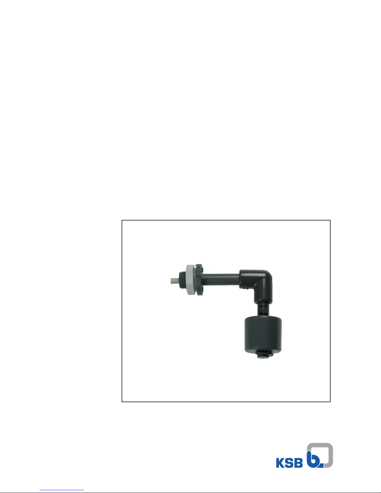
Magnetic Float Switch
M 1 (K) Alarm Contactor
M 1 for AS 0, 2, 4, 5, AS W4, AS W8
M 1 K for AS 1-M and washing machine interrupter
GEWAS 191 AN GL
Installation/Operating Manual

Legal information/Copyright
Installation/Operating Manual M 1 (K) Alarm Contactor
Original operating manual
All rights reserved. The contents provided herein must neither be distributed, copied, reproduced,
edited or processed for any other purpose, nor otherwise transmitted, published or made available to a
third party without the manufacturer's express written consent.
Subject to technical modification without prior notice.
© KSB SE & Co. KGaA, Frankenthal 14/12/2017

Contents
3 of 20
M 1 (K) Alarm Contactor
Contents
Glossary .................................................................................................................................................. 4
1 General.................................................................................................................................................... 5
1.1 Principles ...........................................................................................................................................................5
1.2 Target group.....................................................................................................................................................5
1.3 Other applicable documents............................................................................................................................5
1.4 Symbols .............................................................................................................................................................5
2 Safety...................................................................................................................................................... 6
2.1 Key to safety symbols/markings.......................................................................................................................6
2.2 General..............................................................................................................................................................6
2.3 Intended use .....................................................................................................................................................6
2.4 Personnel qualification and training...............................................................................................................6
2.5 Consequences and risks caused by non-compliance with this manual .........................................................7
2.6 Safety awareness ..............................................................................................................................................7
3 Transport/Temporary Storage/Disposal............................................................................................... 8
3.1 Checking the condition upon delivery............................................................................................................8
3.2 Transport...........................................................................................................................................................8
3.3 Storage/preservation........................................................................................................................................8
3.4 Disposal .............................................................................................................................................................8
4 Description.............................................................................................................................................. 9
4.1 General description ..........................................................................................................................................9
4.2 Designation.......................................................................................................................................................9
4.3 Name plate........................................................................................................................................................9
4.4 Design details....................................................................................................................................................9
4.5 Technical data.................................................................................................................................................10
5 Installation at Site................................................................................................................................ 11
5.1 Safety regulations...........................................................................................................................................11
5.2 Installation in Ama-Drainer-Box Mini ...........................................................................................................11
5.3 Installation in Ama-Drainer-Box 1U/1B - single-pump units ........................................................................12
5.4 Installation in Ama-Drainer-Box Z2 U/Z2 B - dual-pump units ....................................................................13
5.5 Electrical connection ......................................................................................................................................14
6 Commissioning/start-up ...................................................................................................................... 15
6.1 Prerequisites for commissioning/start-up......................................................................................................15
6.2 Commissioning................................................................................................................................................15
7 Maintenance......................................................................................................................................... 16
8 Trouble-shooting.................................................................................................................................. 17
9 Related Documents.............................................................................................................................. 18
9.1 Wiring diagrams .............................................................................................................................................18
Index ..................................................................................................................................................... 19

Glossary
4 of 20
M 1 (K) Alarm Contactor
Glossary
Above-floor box
Automatic waste water lifting unit for above-floor
installation
Alarm contactor
Magnetic float switch that triggers a switching
signal via a reed contact when the liquid level
rises.
Alarm switchgear types AS 0, AS 1-M, AS 2, AS 4,
AS 5
Monitoring unit that outputs an acoustic signal in
conjunction with a contactor. The switchgear
comes with additional functions such as volt-free
contact and battery back-up depending on the
type series.
Alarm switchgear/washing machine interrupter
AS W4, AS W8
Control unit with 4 or 8 intermediate connectors
for connecting up to 4 or 8 washing machines;
automatically de-energises the washing machines
if the water level in the collecting tank of a waste
water lifting unit is too high. Features the
following supplementary functions: alarm buzzer,
indicator lamps for operational availability and
high water, luminous switch for alarm ON/OFF and
M 1 alarm contactor.
Collecting tank
Component of a waste water lifting unit in which
the incoming waste water is stored in
unpressurised condition prior to automatic lifting.
Underfloor box
Automatic waste water lifting unit for underfloor
installation in substructures and foundations.
Washing machine interrupter GEWAS
Control unit with connector housing and outlet
for connecting a washing machine. Including
alarm buzzer and plug connection for an alarm
contactor for automatically de-energising the
washing machine if the water level in the
collecting tank is too high.
Waste water lifting unit
Device for collecting and automatically lifting
faecal-free waste water above the flood level
1 General
5 of 20
M 1 (K) Alarm Contactor
1 General
1.1 Principles
This operating manual is supplied as an integral part of the type series and variants
indicated on the front cover. The manual describes the proper and safe use of this
equipment in all phases of operation.
The name plate indicates the type series, the main operating data and the serial
number. The serial number uniquely describes the system and is used as identification
in all further business processes.
In the event of damage, immediately contact your nearest KSB service centre to
maintain the right to claim under warranty.
1.2 Target group
This operating manual is aimed at the target group of trained and qualified specialist
technical personnel.
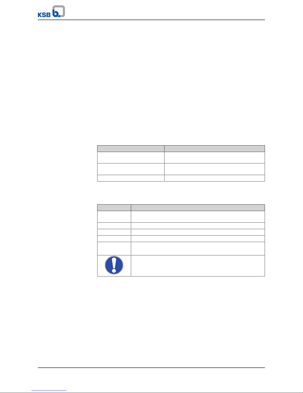
1.3 Other applicable documents
Table1: Overview of other applicable documents
Document Contents
Operating manual(s) for the
pump(s)
Proper and safe use of the pump in all phases of
operation
Operating manual(s) for the
monitoring and control units
Proper and safe use of the monitoring and control
units in all phases of operation
Wiring diagram Electrical connection
1.4 Symbols
Table2: Symbols used in this manual
Symbol Description
✓ Conditions which need to be fulfilled before proceeding with the
step-by-step instructions
⊳ Safety instructions
⇨ Result of an action
⇨ Cross-references
1.
2.
Step-by-step instructions
Note
Recommendations and important information on how to handle
the product

2 Safety
6 of 20
M 1 (K) Alarm Contactor
2 Safety
!
DANGER
All the information in this section refers to hazardous situations.
2.1 Key to safety symbols/markings
Table3: Definition of safety symbols/markings
Symbol Description
!
DANGER
DANGER
This signal word indicates a high-risk hazard which, if not avoided,
will result in death or serious injury.
!
WARNING
WARNING
This signal word indicates a medium-risk hazard which, if not
avoided, could result in death or serious injury.
CAUTION
CAUTION
This signal word indicates a hazard which, if not avoided, could
result in damage to the machine and its functions.
General hazard
In conjunction with one of the signal words this symbol indicates a
hazard which will or could result in death or serious injury.
Electrical hazard
In conjunction with one of the signal words this symbol indicates a
hazard involving electrical voltage and identifies information about
protection against electrical voltage.
Machine damage
In conjunction with the signal word CAUTION this symbol indicates
a hazard for the machine and its functions.
2.2 General
This manual contains general installation, operating, and maintenance instructions
that must be observed to ensure that the float switch is operated safely as well as to
prevent injury and damage to property.
The safety information in all sections of this manual must be complied with.
The manual must be read and fully understood by the specialist personnel/operators
responsible prior to installation and commissioning.
The contents of this manual must be available to the specialist personnel on site at all
times. Instructions attached directly to the float switch must always be complied with
and kept in a perfectly legible condition. This applies to, for example:
▪ Markings for connections
▪ Name plate
The operator is responsible for ensuring compliance with all local regulations not
taken into account in this manual.
2.3 Intended use
The values specified in the technical documentation for the mains voltage, mains
frequency, ambient temperature, and motor current must not be exceeded. The float
switch must only be operated in accordance with the instructions provided in the
operating manual and other applicable documents .
2.4 Personnel qualification and training
All personnel involved must be fully qualified to transport, install, operate, maintain
and inspect the machinery this manual refers to. The responsibilities, competence and
supervision of all personnel involved in installation, operation, maintenance and
inspection must be clearly defined by the operator.
 Loading...