

Page 1
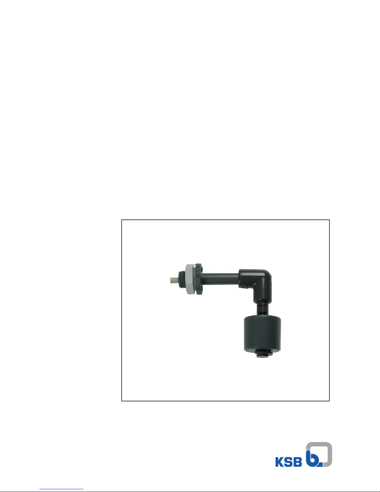
Magnetic Float Switch
M 1 (K) Alarm Contactor
M 1 for AS 0, 2, 4, 5, AS W4, AS W8
M 1 K for AS 1-M and washing machine interrupter
GEWAS 191 AN GL
Installation/Operating Manual
Page 2

Legal information/Copyright
Installation/Operating Manual M 1 (K) Alarm Contactor
Original operating manual
All rights reserved. The contents provided herein must neither be distributed, copied, reproduced,
edited or processed for any other purpose, nor otherwise transmitted, published or made available to a
third party without the manufacturer's express written consent.
Subject to technical modification without prior notice.
© KSB SE & Co. KGaA, Frankenthal 14/12/2017
Page 3

Contents
3 of 20
M 1 (K) Alarm Contactor
Contents
Glossary .................................................................................................................................................. 4
1 General.................................................................................................................................................... 5
1.1 Principles ...........................................................................................................................................................5
1.2 Target group.....................................................................................................................................................5
1.3 Other applicable documents............................................................................................................................5
1.4 Symbols .............................................................................................................................................................5
2 Safety...................................................................................................................................................... 6
2.1 Key to safety symbols/markings.......................................................................................................................6
2.2 General..............................................................................................................................................................6
2.3 Intended use .....................................................................................................................................................6
2.4 Personnel qualification and training...............................................................................................................6
2.5 Consequences and risks caused by non-compliance with this manual .........................................................7
2.6 Safety awareness ..............................................................................................................................................7
3 Transport/Temporary Storage/Disposal............................................................................................... 8
3.1 Checking the condition upon delivery............................................................................................................8
3.2 Transport...........................................................................................................................................................8
3.3 Storage/preservation........................................................................................................................................8
3.4 Disposal .............................................................................................................................................................8
4 Description.............................................................................................................................................. 9
4.1 General description ..........................................................................................................................................9
4.2 Designation.......................................................................................................................................................9
4.3 Name plate........................................................................................................................................................9
4.4 Design details....................................................................................................................................................9
4.5 Technical data.................................................................................................................................................10
5 Installation at Site................................................................................................................................ 11
5.1 Safety regulations...........................................................................................................................................11
5.2 Installation in Ama-Drainer-Box Mini ...........................................................................................................11
5.3 Installation in Ama-Drainer-Box 1U/1B - single-pump units ........................................................................12
5.4 Installation in Ama-Drainer-Box Z2 U/Z2 B - dual-pump units ....................................................................13
5.5 Electrical connection ......................................................................................................................................14
6 Commissioning/start-up ...................................................................................................................... 15
6.1 Prerequisites for commissioning/start-up......................................................................................................15
6.2 Commissioning................................................................................................................................................15
7 Maintenance......................................................................................................................................... 16
8 Trouble-shooting.................................................................................................................................. 17
9 Related Documents.............................................................................................................................. 18
9.1 Wiring diagrams .............................................................................................................................................18
Index ..................................................................................................................................................... 19
Page 4

Glossary
4 of 20
M 1 (K) Alarm Contactor
Glossary
Above-floor box
Automatic waste water lifting unit for above-floor
installation
Alarm contactor
Magnetic float switch that triggers a switching
signal via a reed contact when the liquid level
rises.
Alarm switchgear types AS 0, AS 1-M, AS 2, AS 4,
AS 5
Monitoring unit that outputs an acoustic signal in
conjunction with a contactor. The switchgear
comes with additional functions such as volt-free
contact and battery back-up depending on the
type series.
Alarm switchgear/washing machine interrupter
AS W4, AS W8
Control unit with 4 or 8 intermediate connectors
for connecting up to 4 or 8 washing machines;
automatically de-energises the washing machines
if the water level in the collecting tank of a waste
water lifting unit is too high. Features the
following supplementary functions: alarm buzzer,
indicator lamps for operational availability and
high water, luminous switch for alarm ON/OFF and
M 1 alarm contactor.
Collecting tank
Component of a waste water lifting unit in which
the incoming waste water is stored in
unpressurised condition prior to automatic lifting.
Underfloor box
Automatic waste water lifting unit for underfloor
installation in substructures and foundations.
Washing machine interrupter GEWAS
Control unit with connector housing and outlet
for connecting a washing machine. Including
alarm buzzer and plug connection for an alarm
contactor for automatically de-energising the
washing machine if the water level in the
collecting tank is too high.
Waste water lifting unit
Device for collecting and automatically lifting
faecal-free waste water above the flood level
Page 5
1 General
5 of 20
M 1 (K) Alarm Contactor
1 General
1.1 Principles
This operating manual is supplied as an integral part of the type series and variants
indicated on the front cover. The manual describes the proper and safe use of this
equipment in all phases of operation.
The name plate indicates the type series, the main operating data and the serial
number. The serial number uniquely describes the system and is used as identification
in all further business processes.
In the event of damage, immediately contact your nearest KSB service centre to
maintain the right to claim under warranty.
1.2 Target group
This operating manual is aimed at the target group of trained and qualified specialist
technical personnel.
1.3 Other applicable documents
Table1: Overview of other applicable documents
Document Contents
Operating manual(s) for the
pump(s)
Proper and safe use of the pump in all phases of
operation
Operating manual(s) for the
monitoring and control units
Proper and safe use of the monitoring and control
units in all phases of operation
Wiring diagram Electrical connection
1.4 Symbols
Table2: Symbols used in this manual
Symbol Description
✓ Conditions which need to be fulfilled before proceeding with the
step-by-step instructions
⊳ Safety instructions
⇨ Result of an action
⇨ Cross-references
1.
2.
Step-by-step instructions
Note
Recommendations and important information on how to handle
the product
Page 6

2 Safety
6 of 20
M 1 (K) Alarm Contactor
2 Safety
!
DANGER
All the information in this section refers to hazardous situations.
2.1 Key to safety symbols/markings
Table3: Definition of safety symbols/markings
Symbol Description
!
DANGER
DANGER
This signal word indicates a high-risk hazard which, if not avoided,
will result in death or serious injury.
!
WARNING
WARNING
This signal word indicates a medium-risk hazard which, if not
avoided, could result in death or serious injury.
CAUTION
CAUTION
This signal word indicates a hazard which, if not avoided, could
result in damage to the machine and its functions.
General hazard
In conjunction with one of the signal words this symbol indicates a
hazard which will or could result in death or serious injury.
Electrical hazard
In conjunction with one of the signal words this symbol indicates a
hazard involving electrical voltage and identifies information about
protection against electrical voltage.
Machine damage
In conjunction with the signal word CAUTION this symbol indicates
a hazard for the machine and its functions.
2.2 General
This manual contains general installation, operating, and maintenance instructions
that must be observed to ensure that the float switch is operated safely as well as to
prevent injury and damage to property.
The safety information in all sections of this manual must be complied with.
The manual must be read and fully understood by the specialist personnel/operators
responsible prior to installation and commissioning.
The contents of this manual must be available to the specialist personnel on site at all
times. Instructions attached directly to the float switch must always be complied with
and kept in a perfectly legible condition. This applies to, for example:
▪ Markings for connections
▪ Name plate
The operator is responsible for ensuring compliance with all local regulations not
taken into account in this manual.
2.3 Intended use
The values specified in the technical documentation for the mains voltage, mains
frequency, ambient temperature, and motor current must not be exceeded. The float
switch must only be operated in accordance with the instructions provided in the
operating manual and other applicable documents .
2.4 Personnel qualification and training
All personnel involved must be fully qualified to transport, install, operate, maintain
and inspect the machinery this manual refers to. The responsibilities, competence and
supervision of all personnel involved in installation, operation, maintenance and
inspection must be clearly defined by the operator.
Page 7

2 Safety
7 of 20
M 1 (K) Alarm Contactor
Deficits in knowledge must be rectified by means of training and instruction
provided by sufficiently trained specialist personnel. If required, the operator can
commission the manufacturer/supplier to train the personnel.
2.5 Consequences and risks caused by non-compliance with this manual
▪ Non-compliance with this operating manual will lead to forfeiture of warranty
cover and of any and all rights to claims for damages.
▪ Non-compliance can, for example, have the following consequences:
– Hazards to persons due to electrical, thermal, mechanical and chemical
effects and explosions
– Failure of important product functions
– Failure of prescribed maintenance and servicing practices
– Hazard to the environment due to leakage of hazardous substances
2.6 Safety awareness
In addition to the safety information contained in this manual and the intended use,
the following safety regulations shall be complied with:
▪ Accident prevention, health and safety regulations
▪ Explosion protection regulations
▪ Safety regulations for handling hazardous substances
▪ Applicable standards and laws
Page 8

3 Transport/Temporary Storage/Disposal
8 of 20
M 1 (K) Alarm Contactor
3 Transport/Temporary Storage/Disposal
3.1 Checking the condition upon delivery
1. On transfer of goods, check each packaging unit for damage.
2. In the event of in-transit damage, assess the exact damage, document it and
notify KSB or the supplying dealer (as applicable) and the insurer about the
damage in writing immediately.
3.2 Transport
CAUTION
Improper transport
Damage to the float switch!
▷ Always transport the float switch properly and in its original packaging.
▷ For transport observe the transport instructions on the original packaging.
1. Upon receipt, unpack the float switch and check for in-transit damage.
2. Report any in-transit damage to the manufacturer immediately.
3. Dispose of packaging material in accordance with local regulations.
3.3 Storage/preservation
If the ambient conditions for storage are met, the function of the float switch is
safeguarded even after a prolonged period of storage.
CAUTION
Damage during storage by humidity, dirt or vermin
Corrosion/contamination of the float switch!
▷ Store the float switch under dry and vibration-free conditions, if possible in its
original packaging.
▷ Store the float switch in a dry room where the atmospheric humidity is as
constant as possible.
3.4 Disposal
NOTE
Once decommissioned, the float switch must be properly disposed of in accordance
with local regulations.
Page 9

4 Description
9 of 20
M 1 (K) Alarm Contactor
4 Description
4.1 General description
M 1 alarm contactor
The M 1 alarm contactor is a float switch that automatically sets KSB alarm switchgear
AS0, AS2, AS4, AS5, ASW4 or ASW8 to alarm status when the water level in the
collecting tank of the Ama-Drainer-Box is too high.
M 1 K alarm contactor
The M 1 K alarm contactor is a float switch that responds when the water level in the
collecting tank of the Ama-Drainer-Box is too high by
- automatically sending an alarm signal to the KSB AS 1-M alarm switchgear and
- automatically triggering an acoustic warning signal in washing machine interrupter
GEWAS191ANGL, causing the devices connected to the interrupter to be deenergised.
4.2 Designation
Example: M 1 K alarm contactor
Table4: Key to the designation
Code Description
Alarm contactor Type series
M Magnetic float switch
1 Code number
K With contact plug (for washing machine interrupter only)
4.3 Name plate
6
5
4
1
2
3
Fig.1: Example of name plate for alarm contactor
1 Manufacturer 2 Type series
3 Rated voltage 4 Serial number
5 Switching capacity 6 Start-up current
4.4 Design details
▪ The M 1(K) alarm contactor is a magnetic float switch working according to the
non-contacting principle.
▪ It comprises:
– A connection element with PG7 cable gland
– A 5 m connection cable (2x0.34mm2)
– A sensor tube with a reed contact and the float
As the liquid level rises, the float with the incorporated annular magnet moves
upwards.
In the switching range of the reed contact, the resulting magnetic action triggers a
switching signal.
If the float leaves the contact’s range as the liquid level drops, the reed contact will
return to its original position.
Page 10

4 Description
10 of 20
M 1 (K) Alarm Contactor
4.5 Technical data
Performance data
Table5: Performance data
Characteristic Value
Switching voltage 12V =
Start-up current Max.0.5A
Switching capacity 10VA
Temperature range Up to +60 °C
Enclosure IP67
Immersion depth 2m
Immersion time 7 days
Initial function Circuit closed in upper float position (NO
contact)
Category of use AC-21A and DC-21A to
DINVDE0660T107
IEC947-3-1, EN60947-3-1
NOTE
Always observe contact protection for inductive loads!
Page 11

5 Installation at Site
11 of 20
M 1 (K) Alarm Contactor
5 Installation at Site
5.1 Safety regulations
DANGER
Electrical connection work by unqualified personnel
Danger of death from electric shock!
▷ Always have the electrical connections installed by a trained and qualified
electrician.
▷ Observe regulations IEC 60364 (DIN VDE 0100).
DANGER
Power supply not disconnected
Danger to life!
▷ Pull the mains plug or disconnect all electrical connections and secure against
unintentional start-up.
DANGER
Flooding of control unit
Danger of death from electric shock!
▷ Operate the control unit in flood-proof rooms only.
5.2 Installation in Ama-Drainer-Box Mini
900
550.02
550.01
732.01
81-45
M1
655
Fig.2: Fitting the bracket
550.01 Disc, Ø21/7mm 550.02 Disc, Ø 19/8.5mm
655 Pump 732.01 Bracket
734 M 16 cable gland 81-45 Float switch
Page 12

5 Installation at Site
12 of 20
M 1 (K) Alarm Contactor
900 Self-tapping screw
M1 Drilled hole, Ø2.8mm M2 Drilled hole, Ø16mm
1. Screw float switch 81-45 to bracket 732.01.
2. Fit the bracket on pump 655 (M1 hole) using the fasteners supplied.
27
280
M2
Fig.3: Drilling the cable entry; dimensions [mm]
3. Route the connection cable through the rear tank wall. For this purpose, drill M2
hole (Ø16mm). (Debur the edges.) Seal it with the cable gland 734 supplied.
NOTE
Keep the cable length inside the tank as short as possible.
734
734
81-45 81-45
Fig.4: Installation drawing of M 1 (K) alarm contactor in Ama-Drainer-Box Mini
5.3 Installation in Ama-Drainer-Box 1U/1B - single-pump units
1. Fasten clamp 733 to bracket 732.02 using cheese head screw 900, disc 550, and
hexagon nut 920.
2. Fasten float switch 81-45 to the bracket (width across flats 17); see alarm
contactor M1 (K) installation drawing below.
3. Connect the pre-assembled bracket with float switch to the anti-rotation device
720.02 above the pump handle in the collecting tank.
Make sure it is firmly seated on the anti-rotation device!
– Underfloor installation
The connection cable is pulled through the cable duct or the vent pipe.
– Above-floor installation
The connection cable is routed through the tank wall.
For this purpose, drill an M1 hole (Ø16mm) and seal it with the cable gland
734 supplied.
NOTE
Placing the bracket at a slight angle (no more than30 degrees to the vertical) will
not compromise the performance of the float switch.
Page 13

5 Installation at Site
13 of 20
M 1 (K) Alarm Contactor
M1
734
720.02
81-45
460 mm
732.02
733
550
900
920
Fig.5: Installation drawing of M 1 (K) alarm contactor in Ama-Drainer-Box 1U/1B
550 Disc 720.02 Anti-rotation device
732.02 Bracket 733 Clamp
734 M 16 cable gland 81-45 Float switch
900 Cheese head screw 920 Hexagon nut
M1 Drilled hole, Ø16mm
5.4 Installation in Ama-Drainer-Box Z2 U/Z2 B - dual-pump units
1. Fasten float switch 81-45 to bracket 732.02 (width across flats 17); see alarm
contactor M 1 (K) installation drawing below.
2. Fasten the pre-assembled bracket with float switch to cross beam 573 using
cheese head screws 900, discs 550, and hexagon nuts 920.
– Underfloor installation
Pull the connection cable through the cable duct or the vent pipe.
– Above-floor installation
Route the connection cable through the tank wall near connector panel 6
(see section 9 of the Ama-Drainer-Box operating manual).
For this purpose, drill a hole (Ø16mm) and seal it with the cable gland 734
supplied.
Page 14

5 Installation at Site
14 of 20
M 1 (K) Alarm Contactor
81-45
732.02
550
900
920
573
Fig.6: Installation drawing of M 1 (K) alarm contactor in Ama-Drainer-Box Z2U/Z2B
550 Disc (2) 573 Cross beam
732.02 Bracket 734 M 16 cable gland
81-45 Float switch 900 Cheese head screw (2)
920 Hexagon nut (2)
5.5 Electrical connection
DANGER
Work on the pump set by unqualified personnel
Danger of death from electric shock!
▷ Always have the electrical connections installed by a trained and qualified
electrician.
▷ Observe regulations IEC 60364 (DIN VDE 0100).
M 1 alarm contactor
Please refer to the wiring diagram. (ðSection9.1,Page18)
NOTE
Only KSB alarm switchgear AS0, AS2, AS4, or AS5 may be connected to the alarm
contactor.
M 1 K alarm contactor
1. Connect M 1K alarm contactor to the connector on the underside of the control
unit.
2. Alarm contactor M1 K is ready to be used.
NOTE
Only KSB alarm switchgear AS1-M and the KSB washing machine interrupter may
be connected to the alarm contactor.
Carry out a functional test.
Page 15

6 Commissioning/start-up
15 of 20
M 1 (K) Alarm Contactor
6 Commissioning/start-up
6.1 Prerequisites for commissioning/start-up
Before commissioning/starting up the alarm contactor, ensure that the following
conditions are met:
▪ The information provided in the operating manual for alarm switchgear AS0, AS
1-M, AS2, AS4, AS5, and the washing machine interrupter is complied with.
▪ M 1alarm contactor and alarm switchgear AS0, AS2, AS4, AS5, ASW4 or
ASW8 have been connected in accordance with the wiring diagrams.
6.2 Commissioning
Fig.7: Reed contact open
The M1 (K) alarm contactor works according to the NO principle, i.e. the reed contact
must be open at the lower level. This is indicated by the marking (black dot) on the
upper side of the float.
Page 16

7 Maintenance
16 of 20
M 1 (K) Alarm Contactor
7 Maintenance
Operating reliability will be improved if proper functioning of the contactor is
checked and verified at regular intervals.
The contactor should be checked for deposits every 3 months and cleaned whenever
necessary.
Page 17

8 Trouble-shooting
17 of 20
M 1 (K) Alarm Contactor
8 Trouble-shooting
A
Alarm is not activated
B
Alarm is not deactivated
Table6: Trouble-shooting
A B Possible cause Remedy
✘ No voltage. Check electrical connections.
✘ Reed contact defective Carry out continuity check on alarm
contactor with an ohmmeter; consult
KSB service, if necessary.
✘ ✘ Float blocked by dirt, fibres, or fluff. Clean float and sensor tube.
Page 18

9 Related Documents
18 of 20
M 1 (K) Alarm Contactor
9 Related Documents
9.1 Wiring diagrams
M 1 alarm contactor to alarm switchgear AS0, AS2, AS4, ASW4, ASW8
3
5
AS 0, AS 2, AS 4, ASW4, ASW8M 1
a
b
Fig.8: Wiring diagram for M 1 alarm contactor to alarm switchgear AS0, AS2, AS4,
ASW4, ASW8
a White (WH) b Brown (BN)
M 1 alarm contactor to alarm switchgear AS5
13
14
AS 5
M 1
a
b
Fig.9: Wiring diagram for M 1 alarm contactor to alarm switchgear AS5
a White (WH) b Brown (BN)
Page 19

Index
19 of 20
M 1 (K) Alarm Contactor
Index
C
Commissioning/start-up15
F
Faults
Trouble-shooting17
O
Other applicable documents5
S
Safety awareness7
T
Transport8
Page 20

KSB SE & Co. KGaA
Johann-Klein-Straße 9 • 67227 Frankenthal (Germany)
Tel. +49 6233 86-0
www.ksb.com
2315.813/05-EN
 Loading...