

Page 1

Submersible Borehole Pump with
Integrated Pressure Switch
Ixo-Pro
Installation/Operating Manual
Page 2

Legal information/Copyright
Installation/Operating Manual Ixo-Pro
Original operating manual
All rights reserved. The contents provided herein must neither be distributed, copied, reproduced,
edited or processed for any other purpose, nor otherwise transmitted, published or made available to a
third party without the manufacturer's express written consent.
Subject to technical modification without prior notice.
© KSB SE & Co. KGaA, Frankenthal 09/02/2018
Page 3

Contents
3 of 28
Ixo-Pro
Contents
Glossary .................................................................................................................................................. 4
1 General.................................................................................................................................................... 5
1.1 Principles ...........................................................................................................................................................5
1.2 Target group.....................................................................................................................................................5
1.3 Symbols .............................................................................................................................................................5
2 Safety...................................................................................................................................................... 6
2.1 Key to safety symbols/markings.......................................................................................................................6
2.2 General..............................................................................................................................................................6
2.3 Intended use .....................................................................................................................................................7
2.4 Personnel qualification and training...............................................................................................................7
2.5 Consequences and risks caused by non-compliance with this manual .........................................................7
2.6 Safety awareness ..............................................................................................................................................7
2.7 Safety information for the operator/user.......................................................................................................8
2.8 Safety information for maintenance, inspection and installation ................................................................8
2.9 Unauthorised modes of operation..................................................................................................................8
3 Transport/Temporary Storage/Disposal............................................................................................... 9
3.1 Checking the condition upon delivery............................................................................................................9
3.2 Transport...........................................................................................................................................................9
3.3 Storage/preservation........................................................................................................................................9
3.4 Return to supplier...........................................................................................................................................10
3.5 Disposal ...........................................................................................................................................................10
4 Description............................................................................................................................................ 11
4.1 General description ........................................................................................................................................11
4.2 Designation.....................................................................................................................................................11
4.3 Name plate......................................................................................................................................................11
4.4 Design details..................................................................................................................................................11
4.5 Configuration and function...........................................................................................................................13
4.6 Scope of supply...............................................................................................................................................13
4.7 Dimensions......................................................................................................................................................14
5 Installation at Site................................................................................................................................ 15
5.1 Installing the pump set ..................................................................................................................................15
5.2 Connecting the piping ...................................................................................................................................16
5.3 Electrical connection ......................................................................................................................................17
6 Commissioning/Start-up/Shutdown................................................................................................... 18
6.1 Commissioning/Start-up.................................................................................................................................18
6.1.1 Starting up and stopping ..................................................................................................................18
6.2 Operating data ...............................................................................................................................................18
6.3 Operating limits..............................................................................................................................................19
6.4 Taking the pump set out of service...............................................................................................................19
7 Servicing/Maintenance........................................................................................................................ 20
7.1 Maintenance/inspection.................................................................................................................................20
8 Trouble-shooting.................................................................................................................................. 21
9 Related Documents.............................................................................................................................. 22
9.1 General assembly drawing.............................................................................................................................22
9.2 Exploded view.................................................................................................................................................23
10 EC Declaration of Conformity ............................................................................................................. 25
11 Certificate of Decontamination........................................................................................................... 26
Index ..................................................................................................................................................... 27
Page 4

Glossary
4 of 28
Ixo-Pro
Glossary
Certificate of decontamination
A certificate of decontamination is enclosed by the
customer when returning the product to the
manufacturer to certify that the product has been
properly drained to eliminate any environmental
and health hazards arising from components in
contact with the fluid handled.
Close-coupled design
Motor directly fitted to the pump via a flange or a
drive lantern
Pump
Machine without drive, additional components or
accessories
Pump set
Complete pump set consisting of pump, drive,
additional components and accessories
Page 5
1 General
5 of 28
Ixo-Pro
1 General
1.1 Principles
This operating manual is supplied as an integral part of the type series and variants
indicated on the front cover. The manual describes the proper and safe use of this
equipment in all phases of operation.
The name plate indicates the type series / size and the main operating data.
In the event of damage, immediately contact your nearest KSB service centre to
maintain the right to claim under warranty.
1.2 Target group
This operating manual is aimed at the target group of trained and qualified specialist
technical personnel. (ðSection2.4,Page7)
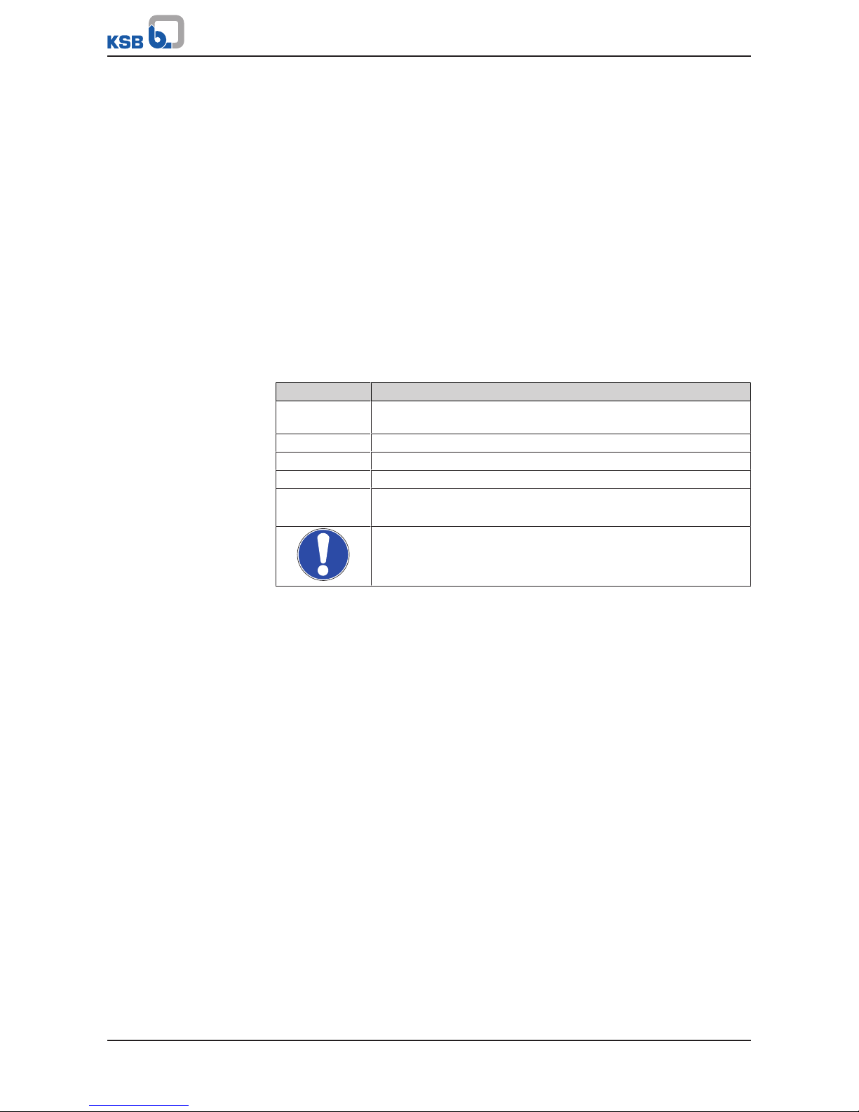
1.3 Symbols
Table1: Symbols used in this manual
Symbol Description
✓ Conditions which need to be fulfilled before proceeding with the
step-by-step instructions
⊳ Safety instructions
⇨ Result of an action
⇨ Cross-references
1.
2.
Step-by-step instructions
Note
Recommendations and important information on how to handle
the product
Page 6
2 Safety
6 of 28
Ixo-Pro
2 Safety
!
DANGER
All the information contained in this section refers to hazardous situations.
In addition to the present general safety information the action-related safety
information given in the other sections must be observed.
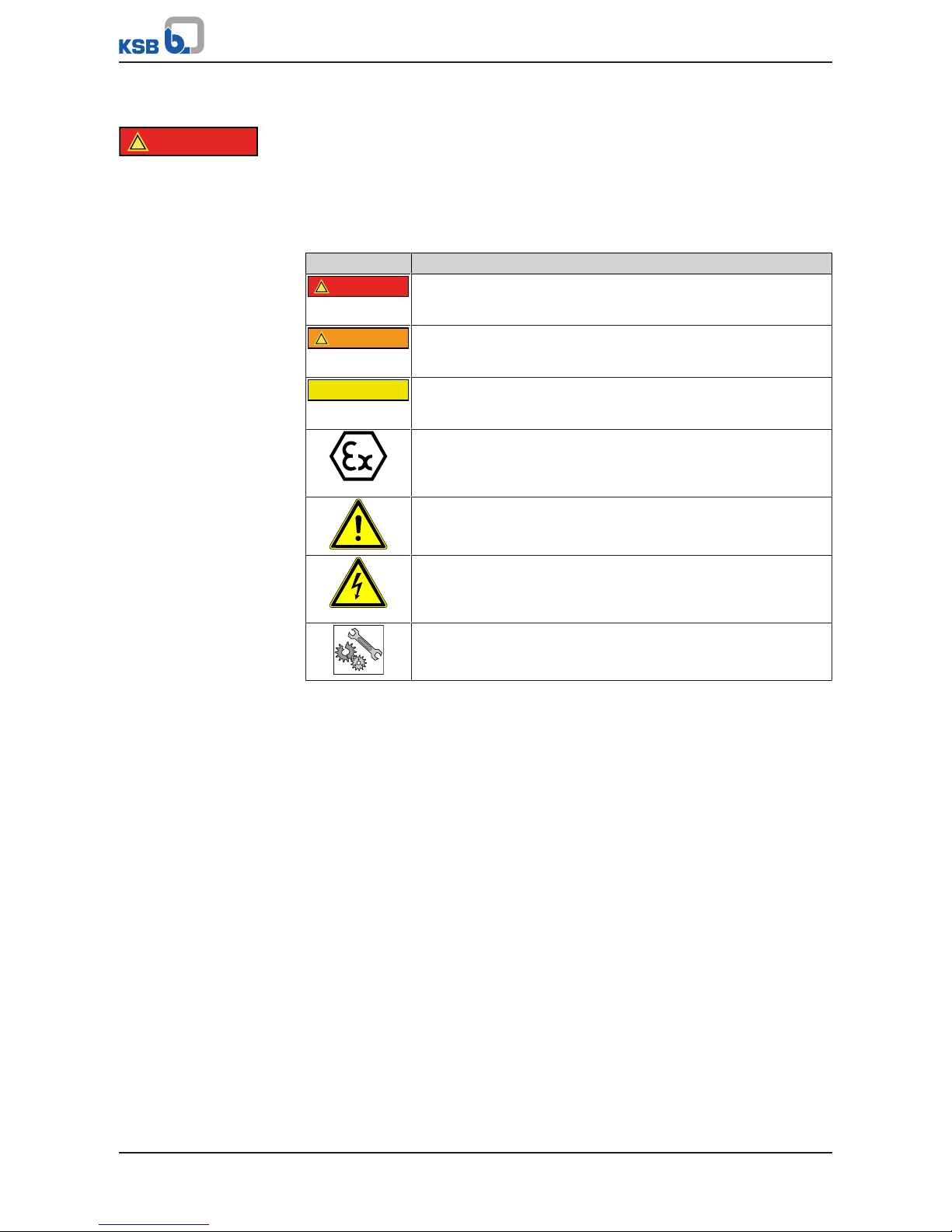
2.1 Key to safety symbols/markings
Table2: Definition of safety symbols/markings
Symbol Description
!
DANGER
DANGER
This signal word indicates a high-risk hazard which, if not avoided,
will result in death or serious injury.
!
WARNING
WARNING
This signal word indicates a medium-risk hazard which, if not
avoided, could result in death or serious injury.
CAUTION
CAUTION
This signal word indicates a hazard which, if not avoided, could
result in damage to the machine and its functions.
Explosion protection
This symbol identifies information about avoiding explosions in
potentially explosive atmospheres in accordance with EU Directive
2014/34/EU (ATEX).
General hazard
In conjunction with one of the signal words this symbol indicates a
hazard which will or could result in death or serious injury.
Electrical hazard
In conjunction with one of the signal words this symbol indicates a
hazard involving electrical voltage and identifies information about
protection against electrical voltage.
Machine damage
In conjunction with the signal word CAUTION this symbol indicates
a hazard for the machine and its functions.
2.2 General
This manual contains general installation, operating and maintenance instructions
that must be observed to ensure safe pump operation and prevent personal injury
and damage to property.
The safety information in all sections of this manual must be complied with.
This manual must be read and completely understood by the specialist personnel/
operators responsible prior to installation and commissioning.
The contents of this manual must be available to the specialist personnel at the site
at all times.
Information attached directly to the pump must always be complied with and be
kept in a perfectly legible condition at all times. This applies to, for example:
▪ Arrow indicating the direction of rotation
▪ Markings for connections
▪ Name plate
The operator is responsible for ensuring compliance with all local regulations not
taken into account in this manual.
Page 7

2 Safety
7 of 28
Ixo-Pro
2.3 Intended use
▪ The pump (set) must only be operated in the fields of application and within the
use limits specified in the other applicable documents.
▪ Only operate pumps/pump sets which are in perfect technical condition.
▪ Do not operate the pump (set) in partially assembled condition.
▪ Only use the pump to handle the fluids described in the data sheet or product
literature of the pump model or variant.
▪ Never operate the pump without the fluid to be handled.
▪ Observe the minimum flow rates indicated in the data sheet or product literature
(to prevent overheating, bearing damage, etc).
▪ Observe the minimum flow rate and maximum flow rate indicated in the data
sheet or product literature (to prevent overheating, mechanical seal damage,
cavitation damage, bearing damage, etc).
▪ Do not throttle the flow rate on the suction side of the pump (to prevent
cavitation damage).
▪ Consult the manufacturer about any use or mode of operation not described in
the data sheet or product literature.
2.4 Personnel qualification and training
All personnel involved must be fully qualified to transport, install, operate, maintain
and inspect the machinery this manual refers to.
The responsibilities, competence and supervision of all personnel involved in
transport, installation, operation, maintenance and inspection must be clearly
defined by the operator.
Deficits in knowledge must be rectified by means of training and instruction
provided by sufficiently trained specialist personnel. If required, the operator can
commission the manufacturer/supplier to train the personnel.
Training on the pump (set) must always be supervised by technical specialist
personnel.
2.5 Consequences and risks caused by non-compliance with this manual
▪ Non-compliance with this operating manual will lead to forfeiture of warranty
cover and of any and all rights to claims for damages.
▪ Non-compliance can, for example, have the following consequences:
– Hazards to persons due to electrical, thermal, mechanical and chemical
effects and explosions
– Failure of important product functions
– Failure of prescribed maintenance and servicing practices
– Hazard to the environment due to leakage of hazardous substances
2.6 Safety awareness
In addition to the safety information contained in this manual and the intended use,
the following safety regulations shall be complied with:
▪ Accident prevention, health and safety regulations
▪ Explosion protection regulations
▪ Safety regulations for handling hazardous substances
▪ Applicable standards, directives and laws
Page 8

2 Safety
8 of 28
Ixo-Pro
2.7 Safety information for the operator/user
▪ Fit protective equipment (e.g. contact guards) supplied by the operator for hot,
cold or moving parts, and check that the equipment functions properly.
▪ Do not remove any protective equipment (e.g. contact guards) during operation.
▪ Provide the personnel with protective equipment and make sure it is used.
▪ Contain leakages (e.g. at the shaft seal) of hazardous fluids handled (e.g.
explosive, toxic, hot) so as to avoid any danger to persons and the environment.
Adhere to all relevant laws.
▪ Eliminate all electrical hazards. (In this respect refer to the applicable national
safety regulations and/or regulations issued by the local energy supply
companies.)
▪ If shutting down the pump does not increase potential risk, fit an emergency-
stop control device in the immediate vicinity of the pump (set) during pump set
installation.
2.8 Safety information for maintenance, inspection and installation
▪ Modifications or alterations of the pump (set) are only permitted with the
manufacturer's prior consent.
▪ Use only original spare parts or parts/components authorised by the
manufacturer. The use of other parts/components can invalidate any liability of
the manufacturer for resulting damage.
▪ The operator ensures that maintenance, inspection and installation is performed
by authorised, qualified specialist personnel who are thoroughly familiar with
the manual.
▪ Only carry out work on the pump (set) during standstill of the pump.
▪ Only perform work on the pump set when it has been disconnected from the
power supply (de-energised).
▪ The pump (set) must have cooled down to ambient temperature.
▪ Pump pressure must have been released and the pump must have been drained.
▪ When taking the pump set out of service always adhere to the procedure
described in the manual.
▪ Decontaminate pumps which handle fluids posing a health hazard.
▪ As soon as the work has been completed, re-install and re-activate any safety-
relevant devices and protective devices. Before returning the product to service,
observe all instructions on commissioning. (ðSection6.1,Page18)
2.9 Unauthorised modes of operation
Never operate the pump (set) outside the limits stated in the data sheet and in this
manual.
The warranty relating to the operating reliability and safety of the supplied pump
(set) is only valid if the equipment is used in accordance with its intended use.
(ðSection2.3,Page7)
Page 9

3 Transport/Temporary Storage/Disposal
9 of 28
Ixo-Pro
3 Transport/Temporary Storage/Disposal
3.1 Checking the condition upon delivery
1. On transfer of goods, check each packaging unit for damage.
2. In the event of in-transit damage, assess the exact damage, document it and
notify KSB or the supplying dealer and the insurer about the damage in writing
immediately.
NOTE
The pump set is supplied by the manufacturer/supplier in packaging which largely
prevents sagging or other damage during transport and/or storage.
3.2 Transport
CAUTION
Improper pump transport
Damage to the pump!
▷ Always transport the pump/pump set in the specified position.
▷ Never suspend the pump (set) from the power cable.
▷ Prevent the pump (set) from getting knocked or dropped.
▷ Always secure a pump set in upright position against tipping over.
▷ Wear personal protective equipment.
Use lifting equipment which is suitable for the weight of the pump set.
Make sure that the power cable is not kinked or damaged during transport.
3.3 Storage/preservation
If commissioning is to take place some time after delivery, we recommend that the
following measures be taken:
WARNING
Pump set tilting or rolling off
Risk of personal injury!
▷ Always secure vertically positioned pump sets against tipping over.
▷ Always secure horizontally positioned pump sets against rolling off.
CAUTION
Damage during storage by frost, humidity, dirt, UV radiation or vermin
Corrosion/contamination of the pump!
▷ Store the pump (set) in a dry, dark, frost-proof room not exposed to sunlight
where the atmospheric humidity is as constant as possible.
Store the pump as follows:
▪ In a dry environment
▪ Protected against direct sunlight and heat
▪ Protected against dirt and dust
▪ Protected against freezing
▪ Protected against vermin
Further information on storing the pump set after it has been in use
(ðSection6.4,Page19) .
Page 10

3 Transport/Temporary Storage/Disposal
10 of 28
Ixo-Pro
3.4 Return to supplier
1. Drain the pump as per operating instructions.
2. Flush and clean the pump, particularly if it has been used for handling noxious,
explosive, hot or other hazardous fluids.
3. If the pump has handled fluids whose residues could lead to corrosion damage
in the presence of atmospheric humidity or could ignite upon contact with
oxygen also neutralise the pump and blow through with anhydrous inert gas to
ensure drying.
4. Always complete and enclose a certificate of decontamination when returning
the pump.
Indicate any safety measures and decontamination measures taken.
(ðSection11,Page26)
NOTE
If required, a blank certificate of decontamination can be downloaded from the
following web site: www.ksb.com/certificate_of_decontamination
3.5 Disposal
WARNING
Fluids, consumables and supplies which are hot and/or pose a health hazard
Hazard to persons and the environment!
▷ Collect and properly dispose of flushing fluid and any residues of the fluid
handled.
▷ Wear safety clothing and a protective mask if required.
▷ Observe all legal regulations on the disposal of fluids posing a health hazard.
1. Dismantle the pump (set).
Collect greases and other lubricants during dismantling.
2. Separate and sort the pump materials, e.g. by:
- Metals
- Plastics
- Electronic waste
- Greases and other lubricants
3. Dispose of materials in accordance with local regulations or in another
controlled manner.
Page 11

4 Description
11 of 28
Ixo-Pro
4 Description
4.1 General description
Submersible borehole pump with integrated pressure switch
Pump for handling clean water without suspended solids.
4.2 Designation
Example: Ixo-Pro 4
Table3: Designation key
Code Description
Ixo-Pro Type series
4 Number of stages
4.3 Name plate
H max. 43.1 m
6.2 A
IP-68
P1-1.2kW
10.9 kgP2-0.9kW
H min. 0 m
12
Is.KL.F
S1
2014w21
T.max 35°C
KSB SAS
F- 59320 Sequedin
MADE IN EU
12 m
Ident.Nr: 39300168
IXO-PRO 4
230 50 014655/ESP
Q(l/min) 09-60
H(m) 41.2-9.7
230 V.1 50HZ
12uF-450V
1
2
3
4
5
6
7
8
9
10
12 11131415
16
17
18
19
Fig.1: Name plate
1 Type series, number of stages 2 Material number
3 Minimum head 4 Maximum head
5 Series code 6 Maximum fluid temperature
7 Maximum immersion depth 8 Power input (P1)
9 Weight 10 Thermal class
11 Mode of operation 12 Power output (P2)
13 Nominal current 14 Enclosure
15 Manufacturer/supplier 16 Capacitor
17 Voltage, frequency 18 Range of heads
19 Range of flow rates
4.4 Design details
Design
▪ Centrifugal pump
▪ Close-coupled design
▪ Multistage
▪ Integrated pressure switch
▪ For fully submerged operation
▪ Low-level inlet
Page 12

4 Description
12 of 28
Ixo-Pro
▪ Suction strainer with a maximum mesh width of 2mm
▪ Flow sensor
▪ Swing check valve
Drive
▪ Water-cooled single-phase AC motor
▪ 230V, 50Hz
▪ Thermal class F
▪ IP68 enclosure
▪ Continuous duty
▪ Integrated capacitor
▪ Electronic dry running protection with 4 consecutive start-up attempts
▪ Thermal overload protection
▪ Motor connection cable 15m (H07RNF) and plug
Bearings
▪ Ball bearing
▪ Grease-packed bearings sealed for life
Shaft seal
▪ Double shaft seal with oil reservoir fitted in between
Page 13

4 Description
13 of 28
Ixo-Pro
4.5 Configuration and function
Fig.2: Sectional drawing
1 Suction casing 2 Pump casing
3 Rotor 4 Diffuser
5 Double mechanical seal 6 Rolling element bearing
7 Stator 8 Motor shaft
9 Rolling element bearing 10 Capacitor
The fluid enters the pump via the suction casing (1). It is accelerated outward by the
rotating impellers. In the flow passage of the diffusers (4) and the pump casing (2)
the kinetic energy of the fluid is converted into pressure energy. The fluid is pumped
to the discharge side, where it leaves the pump. At the rear side of the impeller, the
motor shaft (8) enters the casing via the bearing cover. The shaft passage is sealed by
a double mechanical seal (5). The shaft is supported by rolling element bearings (6)
and (9).
4.6 Scope of supply
▪ Multistage submersible borehole pump with integrated pressure switch
▪ Motor connection cable 15m (H07RNF) and plug
Page 14

4 Description
14 of 28
Ixo-Pro
4.7 Dimensions
A
B
C
Fig.3: Dimensions
Table4: Dimensions[mm]
Size Dimensions Thread
A B C
4 493 126 Rp1
6 560 126 Rp1
Page 15

5 Installation at Site
15 of 28
Ixo-Pro
5 Installation at Site
5.1 Installing the pump set
CAUTION
Incorrect installation
Damage to the machine
▷ The pump set must always be installed in a vertical position.
▷ Never suspend the pump set by the power cable or discharge line.
Observe the following when selecting a place of installation:
▪ Never install the pump set directly on the floor of the tank / rainwater storage
tank.
▪ Never install the pump set too close to the inner walls of the tank / rainwater
storage tank.
▪ Observe the installation height (see table: maximum installation height x)
X
Fig.4: Installation information
Table5: Maximum installation height x
Size x [m]
4 20
6 30
1) See cable manufacturer's documentation or DINVDE0298-3.
Page 16

5 Installation at Site
16 of 28
Ixo-Pro
5.2 Connecting the piping
DANGER
Using damaged cables in the tank / rainwater storage tank
Electric shock!
▷ Do not kink the cable. Observe the minimum bending radius1) of the cable. Do
not drag the cable over sharp edges.
▷ Fasten the cable to the riser or piping with suitable fasteners (e.g. cable clips).
▷ Do not use any tools, equipment or accessories with sharp edges (e.g. sharp-
edged pipe sockets) for the installation.
WARNING
Persons falling into unsecured tanks / rainwater storage tanks
Risk of injury!
▷ Always secure open tanks / rainwater storage tanks during the entire
installation procedure to prevent persons from falling in.
▷ Suitably fence off the work area.
CAUTION
Pump set falling into the tank / rainwater storage tank
Damage to the pump set!
▷ Secure the pump set during the entire installation procedure.
▷ Dimension any securing devices (supporting clamps, supports, etc.) so that they
can carry all weights during the installation.
CAUTION
Unsuitable pipeline
Faulty operation of the pump!
▷ If using plastic pipelines, make sure they are designed to withstand the pump
pressure.
▷ Do not kink the plastic pipeline.
CAUTION
Incorrect installation
Pressure surges!
Damage to the material!
▷ Never install an additional swing check valve in the piping. The swing check
valve is already integrated in the pump set.
▷ Fit an expansion vessel to the discharge line (optional accessory: see Kit-Press
connection set).
Installation information
▪ The pumps can be connected to pipelines with an Rp1 thread.
NOTE
Using a discharge line of a larger diameter is recommended in the case of very high
static heads or very long pipelines in order to prevent pressure losses.
1. Install the pipelines in accordance with the manufacturer's documentation.
2. Lower the pump set into the tank / rainwater storage tank.
Page 17

5 Installation at Site
17 of 28
Ixo-Pro
5.3 Electrical connection
DANGER
Electrical connection work by unqualified personnel
Danger of death from electric shock!
▷ Always have the electrical connections installed by a trained and qualified
electrician.
▷ Observe regulations IEC60364.
WARNING
Incorrect connection to the mains
Damage to the mains network, short circuit!
▷ Observe the technical specifications of the local energy supply companies.
DANGER
Connection of damaged power cables
Danger of death from electric shock!
▷ Check the power cables for damage before connecting them.
▷ Never connect damaged power cables.
▷ Replace damaged power cables.
ü Check the available mains voltage against the data on the name plate.
ü The mains is protected by a residual current device of 30mA.
1. Plug the mains plug into the mains socket.
Page 18

6 Commissioning/Start-up/Shutdown
18 of 28
Ixo-Pro
6 Commissioning/Start-up/Shutdown
6.1 Commissioning/Start-up
6.1.1 Starting up and stopping
DANGER
Start-up with defective earth conductor
Personal injury from electric shock!
▷ Never switch on a pump set without an earth conductor or with a defective
earth conductor.
ü The pump set has been properly connected to the power supply.
ü Any shut-off elements in the discharge line are open.
1. The pump starts up automatically as soon as a consumer installation (e.g.
outdoor tap) is opened.
Depending on the length of the pipeline it may take several minutes until the
discharge line is completely filled with the fluid handled.
Start-up and stop are automatic processes. The pump set starts up when a consumer
installation is opened. When it is closed again, the pump stops. The start-up pressure
equals 2 or 3bar, depending on the pump size. If the water consumption exceeds
1.4l/min the pump remains in operation.
1s
60s
I
O
5 s 15 s
1 42 3
Fig.5: Timing of start-up attempts
1, 2, 3, 4 Start-up attempts
Start-up attempts
When the electronic circuit recognises that the fluid handled is not available, the
pump set stops. The pump set will carry out 4 start-up attempts (see Fig.: Timing of
start-up attempts).
If the pump set can not be started up in any of these 4 start-up attempts, the pump
set will be switched off indefinitely. The pump set can only be re-started by manually
switching the power supply off and then on again.
Anti-blockage function
The pump set features an anti-blockage function. After an idle time of 100hours, the
pump set will automatically be started up for 2seconds to prevent the hydraulic
section from blocking.
6.2 Operating data
Table6: Operating properties
Characteristic Value
Flow rate Q [m3/h] ≤ 3.9
Q [l/min] ≤ 65
Head H [m] ≤ 60
Fluid temperature T [°C] 5 - 35
Page 19

6 Commissioning/Start-up/Shutdown
19 of 28
Ixo-Pro
6.3 Operating limits
▪ Only suitable for vertical operation.
▪ Maximum immersion depth: 12m
▪ Maximum particle size: 2mm
▪ Maximum number of start-ups/hour: 30
6.4 Taking the pump set out of service
If the pump set is not in service for a prolonged period of time, taking the following
measures is recommended.
1. Remove the pump set from the tank / rainwater storage tank.
2. Drain the pipelines and the pump set.
3. Store the pump set properly. (ðSection3.3,Page9)
Page 20

7 Servicing/Maintenance
20 of 28
Ixo-Pro
7 Servicing/Maintenance
7.1 Maintenance/inspection
The pump set is maintenance-free.
Page 21

8 Trouble-shooting
21 of 28
Ixo-Pro
8 Trouble-shooting
WARNING
Improper work to remedy faults
Risk of injury!
▷ For any work performed to remedy faults, observe the relevant information
given in this operating manual and/or in the product literature provided by the
accessories manufacturer.
If problems occur that are not described in the following table, consultation with the
KSB customer service is required.
A
Pump is running, but does not deliver
B
Pump delivers insufficient flow rate
C
Pump stops during operation
D
Volume flow does not correspond with the indicated characteristic curve
Table7: Trouble-shooting
A B C D Possible causes Remedy
✘ - - - No power supply Check fuses and other protective devices.
- ✘ - - Fluid level has sunk. Make sure that the pump is submerged in the fluid
handled.
- - ✘ - Voltage error Make sure that the voltage matches the voltage
indicated on the name plate.
- - - ✘ Maximum installation height exceeded Observe the operating limits.
✘ - ✘ - Protection against overheating has tripped. Reset the thermal protection device or wait until the
pump has cooled down.
- ✘ - - Discharge line defective or not connected Check discharge line connection. Replace, if required.
- - - ✘ Water inlet filter clogged Clean the suction filter.
✘ - ✘ - Stop caused by level probes Wait for the water level in the well to rise.
- - - ✘ Hydraulic system worn Contact KSB.
Page 22

9 Related Documents
22 of 28
Ixo-Pro
9 Related Documents
9.1 General assembly drawing
Fig.6: Sectional drawing
1 Suction casing 2 Pump casing
3 Rotor 4 Diffuser
5 Double mechanical seal 6 Rolling element bearing
7 Stator 8 Motor shaft
9 Rolling element bearing 10 Capacitor
Page 23

9 Related Documents
23 of 28
Ixo-Pro
9.2 Exploded view
Fig.7: Exploded view
Page 24

9 Related Documents
24 of 28
Ixo-Pro
Page 25

10 EC Declaration of Conformity
25 of 28
Ixo-Pro
10 EC Declaration of Conformity
Manufacturer: KSB S.A.S.
128, rue Carnot,
59320 Sequedin (France)
The manufacturer herewith declares that the product:
Ixo-Pro
Serial number:2018w01 - 2019w52
▪ is in conformity with the provisions of the following Directives as amended from time to time:
– Pump set: EC Machinery Directive 2006/42/EC
– Pump set: Electromagnetic Compatibility Directive 2014/30/EU
The manufacturer also declares that
▪ the following harmonised international standards have been applied:
– ISO 12100
– EN 809
– EN 60034-1, EN 60034-5/A1
– EN 60335-1/A1, EN 60335-2-41
Person authorised to compile the technical file:
Christian Appel
Head of Product Management Well and Ring-section Pumps
KSB SE & Co. KGaA
Johann-Klein-Straße 9
67227 Frankenthal (Germany)
The EU Declaration of Conformity was issued in/on:
Frankenthal, 1 February 2018
Joachim Schullerer
Head of Product Development Pump Systems and Drives
KSB SE & Co. KGaA
Johann-Klein-Straße 9
67227 Frankenthal
Page 26

11 Certificate of Decontamination
26 of 28
Ixo-Pro
11 Certificate of Decontamination
Type: ................................................................................................................................
Order number/
Order item number2): ................................................................................................................................
Delivery date: ................................................................................................................................
Field of application: ................................................................................................................................
Fluid handled2): ................................................................................................................................
Please tick where applicable2):
Radioactive Explosive Corrosive Toxic
Harmful Bio-hazardous Highly flammable Safe
Reason for return2): ................................................................................................................................
Comments: ................................................................................................................................
................................................................................................................................
The product/accessories have been carefully drained, cleaned and decontaminated inside and outside prior to dispatch/
placing at your disposal.
We herewith declare that this product is free from hazardous chemicals, biological and radioactive substances.
For mag-drive pumps, the inner rotor unit (impeller, casing cover, bearing ring carrier, plain bearing, inner rotor) has been
removed from the pump and cleaned. In cases of containment shroud leakage, the outer rotor, bearing bracket lantern,
leakage barrier and bearing bracket or adapter have also been cleaned.
For canned motor pumps, the rotor and plain bearing have been removed from the pump for cleaning. In cases of leakage at
the stator can, the stator space has been examined for fluid leakage; if fluid handled has penetrated the stator space, it has
been removed.
No special safety precautions are required for further handling.
The following safety precautions are required for flushing fluids, fluid residues and disposal:
...............................................................................................................................................................
...............................................................................................................................................................
We confirm that the above data and information are correct and complete and that dispatch is effected in accordance with the
relevant legal provisions.
.................................................................... ....................................................... .......................................................
Place, date and signature Address Company stamp
2) Required fields
Page 27

Index
27 of 28
Ixo-Pro
Index
B
Bearings12
C
Certificate of decontamination26
Configuration and function13, 22
D
Design11
Designation11
Disposal10
Drive12
F
Faults
Causes and remedies21
Fields of application7
I
Intended use7
K
Key to safety symbols/markings6
N
Name plate11
R
Return to supplier10
S
Safety6
Safety awareness7
Shaft seal12
T
Transport9
W
Warnings6
Page 28

KSB S.A.S.
128, rue Carnot • 59320 Sequedin (France)
B.P. 60095 • 59482 Haubourdin Cedex (France)
Tél. +33 3 2022-7000 • Fax +33 3 2022-7099
www.ksb.com
2150.8/03-EN
 Loading...