

Page 1
Submersible Borehole Pump
Ixo N
Installation/Operating Manual
Page 2

Legal information/Copyright
Installation/Operating Manual Ixo N
Original operating manual
All rights reserved. The contents provided herein must neither be distributed, copied, reproduced,
edited or processed for any other purpose, nor otherwise transmitted, published or made available to a
third party without the manufacturer's express written consent.
Subject to technical modification without prior notice.
© KSB SE & Co. KGaA, Frankenthal 08/01/2019
Page 3

Contents
Contents
Glossary .................................................................................................................................................. 5
1 General.................................................................................................................................................... 6
1.1 Principles ...........................................................................................................................................................6
1.2 Target group.....................................................................................................................................................6
1.3 Symbols .............................................................................................................................................................6
1.4 Key to safety symbols/markings.......................................................................................................................6
2 Safety...................................................................................................................................................... 8
2.1 General..............................................................................................................................................................8
2.2 Intended use .....................................................................................................................................................8
2.3 Personnel qualification and training...............................................................................................................8
2.4 Consequences and risks caused by non-compliance with this manual .........................................................9
2.5 Safety awareness ..............................................................................................................................................9
2.6 Safety information for the operator/user.......................................................................................................9
2.7 Safety information for maintenance, inspection and installation ................................................................9
2.8 Unauthorised modes of operation................................................................................................................10
3 Transport/Temporary Storage/Disposal............................................................................................. 11
3.1 Checking the condition upon delivery..........................................................................................................11
3.2 Transport.........................................................................................................................................................11
3.3 Storage/preservation......................................................................................................................................11
3.4 Return to supplier...........................................................................................................................................12
3.5 Disposal ...........................................................................................................................................................12
4 Description............................................................................................................................................ 13
4.1 General description ........................................................................................................................................13
4.2 Designation.....................................................................................................................................................13
4.3 Name plate......................................................................................................................................................13
4.4 Design details..................................................................................................................................................13
4.5 Configuration and function...........................................................................................................................14
4.6 Scope of supply...............................................................................................................................................14
4.7 Ixo N ................................................................................................................................................................15
5 Installation at Site................................................................................................................................ 16
5.1 Installing the pump set ..................................................................................................................................16
5.2 Connecting the piping ...................................................................................................................................17
5.3 Electrical connection ......................................................................................................................................18
6 Commissioning/Start-up/Shutdown................................................................................................... 20
6.1 Commissioning/Start-up.................................................................................................................................20
6.1.1 Starting up and stopping .................................................................................................................20
6.2 Operating data ...............................................................................................................................................20
6.3 Operating limits..............................................................................................................................................20
6.4 Taking the pump set out of service...............................................................................................................21
7 Servicing/Maintenance........................................................................................................................ 22
7.1 Safety regulations...........................................................................................................................................22
7.2 Maintenance/inspection.................................................................................................................................22
7.2.1 Cleaning the pump set ......................................................................................................................22
7.3 Ordering spare parts ......................................................................................................................................22
7.4 Spare parts ......................................................................................................................................................23
8 Trouble-shooting.................................................................................................................................. 24
9 Related Documents.............................................................................................................................. 26
9.1 General assembly drawing.............................................................................................................................26
9.2 Exploded view.................................................................................................................................................27
Ixo N
3 of 32
Page 4

Contents
10 EU Declaration of Conformity............................................................................................................. 29
11 Certificate of Decontamination........................................................................................................... 30
Index ..................................................................................................................................................... 31
4 of 32
Ixo N
Page 5

Glossary
Glossary
Certificate of decontamination
A certificate of decontamination is enclosed by the
customer when returning the product to the
manufacturer to certify that the product has been
properly drained to eliminate any environmental
and health hazards arising from components in
contact with the fluid handled.
Close-coupled design
Motor directly fitted to the pump via a flange or a
drive lantern
Pump
Machine without drive, additional components or
accessories
Pump set
Complete pump set consisting of pump, drive,
additional components and accessories
Ixo N
5 of 32
Page 6
1 General
!
DANGER
!
WARNING
CAUTION
1 General
1.1 Principles
This operating manual is valid for the type series and variants indicated on the front
cover.
The operating manual describes the proper and safe use of this equipment in all
phases of operation.
The name plate indicates the type series, the main operating data and the serial
number. The serial number uniquely describes the product and is used as
identification in all further business processes.
In the event of damage, immediately contact your nearest KSB Service centre to
maintain the right to claim under warranty.
1.2 Target group
This operating manual is aimed at the target group of trained and qualified specialist
technical personnel. (ðSection2.3,Page8)
1.3 Symbols
Table1: Symbols used in this manual
Symbol Description
✓ Conditions which need to be fulfilled before proceeding with the
step-by-step instructions
⊳ Safety instructions
⇨
⇨ Cross-references
1.
2.
Result of an action
Step-by-step instructions
Note
Recommendations and important information on how to handle
the product
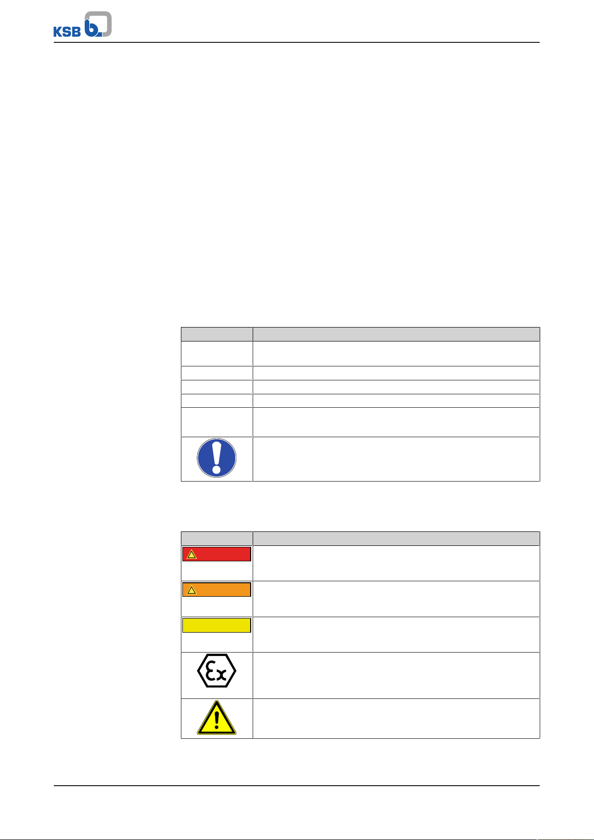
1.4 Key to safety symbols/markings
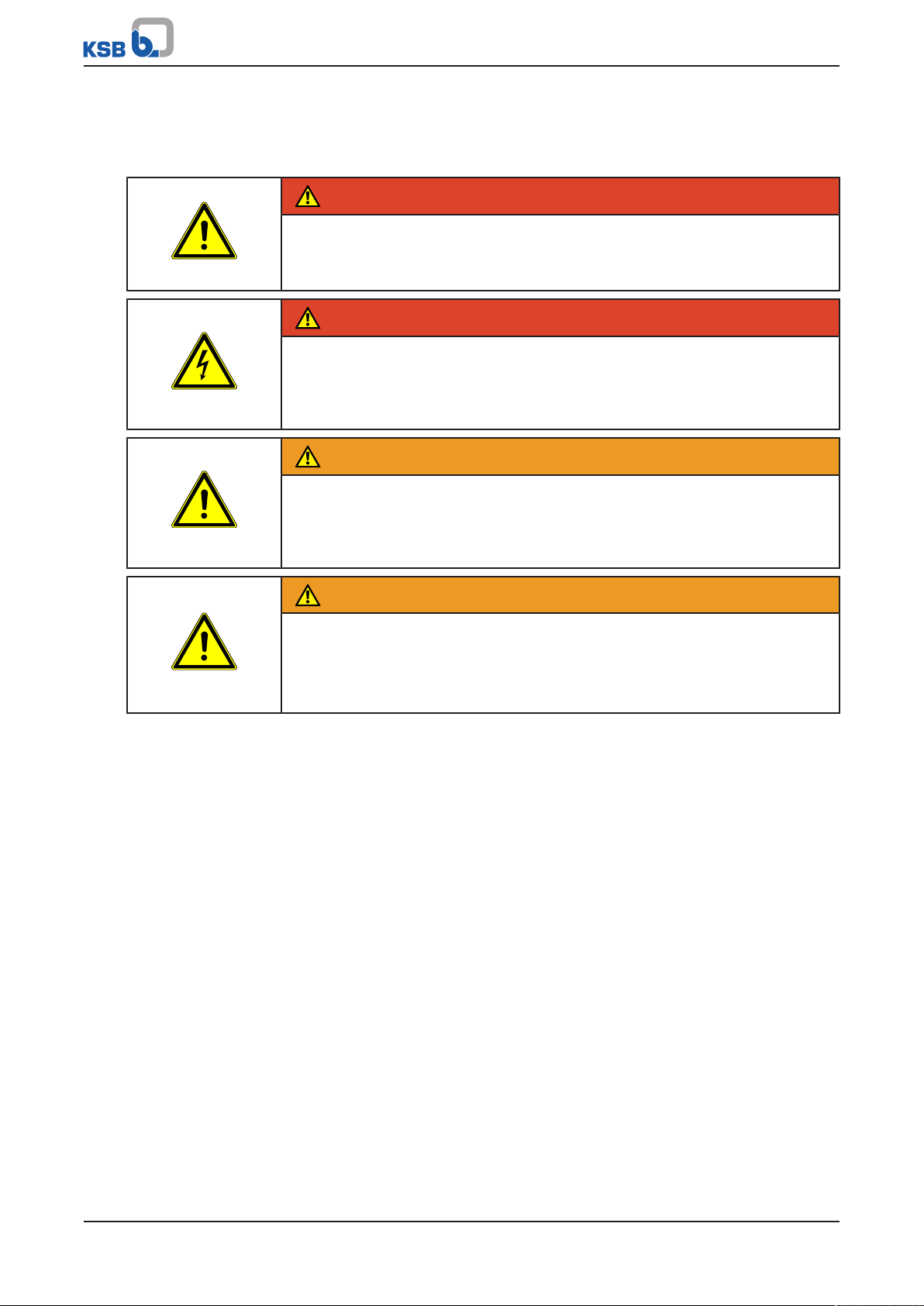
Table2: Definition of safety symbols/markings
Symbol Description
DANGER
This signal word indicates a high-risk hazard which, if not avoided,
will result in death or serious injury.
WARNING
This signal word indicates a medium-risk hazard which, if not
avoided, could result in death or serious injury.
CAUTION
This signal word indicates a hazard which, if not avoided, could
result in damage to the machine and its functions.
Explosion protection
This symbol identifies information about avoiding explosions in
potentially explosive atmospheres in accordance with EU Directive
2014/34/EU (ATEX).
General hazard
In conjunction with one of the signal words this symbol indicates a
hazard which will or could result in death or serious injury.
6 of 32
Ixo N
Page 7
1 General
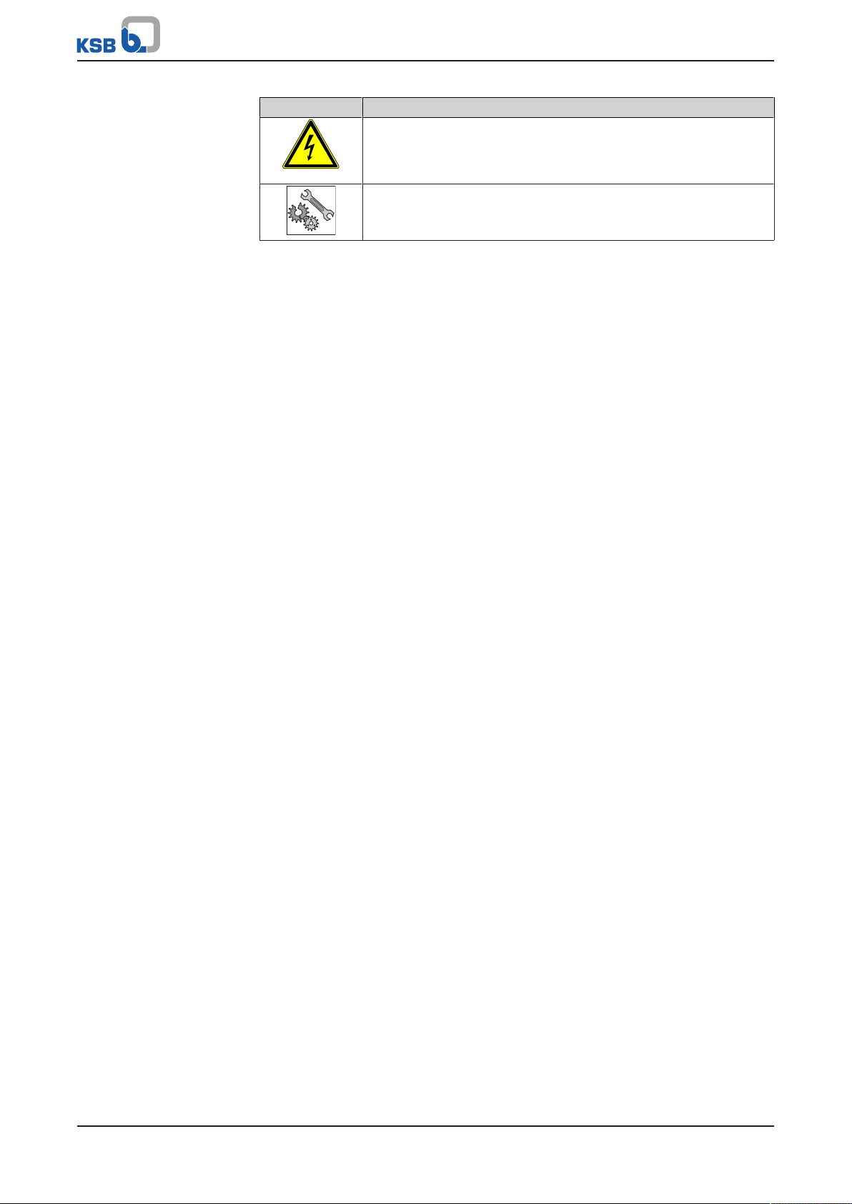
Symbol Description
Electrical hazard
In conjunction with one of the signal words this symbol indicates a
hazard involving electrical voltage and identifies information about
protection against electrical voltage.
Machine damage
In conjunction with the signal word CAUTION this symbol indicates
a hazard for the machine and its functions.
Ixo N
7 of 32
Page 8

2 Safety
!
DANGER
2 Safety
All the information contained in this section refers to hazardous situations.
In addition to the present general safety information the action-related safety
information given in the other sections must be observed.
2.1 General
▪ This operating manual contains general installation, operating and maintenance
instructions that must be observed to ensure safe operation of the system and
prevent personal injury and damage to property.
▪ Comply with all the safety instructions given in the individual sections of this
operating manual.
▪ The operating manual must be read and understood by the responsible specialist
personnel/operators prior to installation and commissioning.
▪ The contents of this operating manual must be available to the specialist
personnel at the site at all times.
▪ Information and markings attached directly to the product must always be
complied with and kept in a perfectly legible condition at all times. This applies
to, for example:
– Arrow indicating the direction of rotation
– Markings for connections
– Type designation
▪ The operator is responsible for ensuring compliance with all local regulations not
taken into account.
2.2 Intended use
▪ The pump (set) must only be operated in the fields of application and within the
use limits specified in the other applicable documents.
▪ Only operate pumps/pump sets which are in perfect technical condition.
▪ Do not operate the pump (set) in partially assembled condition.
▪ Only use the pump to handle the fluids described in the data sheet or product
literature of the pump model or variant.
▪ Never operate the pump without the fluid to be handled.
▪ Observe the minimum flow rates indicated in the data sheet or product literature
(to prevent overheating, bearing damage, etc).
▪ Observe the minimum flow rate and maximum flow rate indicated in the data
sheet or product literature (to prevent overheating, mechanical seal damage,
cavitation damage, bearing damage, etc).
▪ Do not throttle the flow rate on the suction side of the pump (to prevent
cavitation damage).
▪ Consult the manufacturer about any use or mode of operation not described in
the data sheet or product literature.
2.3 Personnel qualification and training
All personnel involved must be fully qualified to transport, install, operate, maintain
and inspect the machinery this manual refers to.
The responsibilities, competence and supervision of all personnel involved in
transport, installation, operation, maintenance and inspection must be clearly
defined by the operator.
Deficits in knowledge must be rectified by means of training and instruction
provided by sufficiently trained specialist personnel. If required, the operator can
commission the manufacturer/supplier to train the personnel.
Training on the pump (set) must always be supervised by technical specialist
personnel.
8 of 32
Ixo N
Page 9

2 Safety
2.4 Consequences and risks caused by non-compliance with this manual
▪ Non-compliance with these operating instructions will lead to forfeiture of
warranty cover and of any and all rights to claims for damages.
▪ Non-compliance can, for example, have the following consequences:
– Hazards to persons due to electrical, thermal, mechanical and chemical
effects and explosions
– Failure of important product functions
– Failure of prescribed maintenance and servicing practices
– Hazard to the environment due to leakage of hazardous substances
2.5 Safety awareness
In addition to the safety information contained in this operating manual and the
intended use, the following safety regulations shall be complied with:
▪ Accident prevention, health regulations and safety regulations
▪ Explosion protection regulations
▪ Safety regulations for handling hazardous substances
▪ Applicable standards, directives and laws
2.6 Safety information for the operator/user
▪ Fit protective equipment (e.g. contact guards) supplied by the operator for hot,
cold or moving parts, and check that the equipment functions properly.
▪ Do not remove any protective equipment (e.g. contact guards) during operation.
▪ Provide the personnel with protective equipment and make sure it is used.
▪ Contain leakages (e.g. at the shaft seal) of hazardous fluids handled (e.g.
explosive, toxic, hot) so as to avoid any danger to persons and the environment.
Adhere to all relevant laws.
▪ Eliminate all electrical hazards. (In this respect refer to the applicable national
safety regulations and/or regulations issued by the local energy supply
companies.)
▪ If shutting down the pump does not increase potential risk, fit an emergency-
stop control device in the immediate vicinity of the pump (set) during pump set
installation.
2.7 Safety information for maintenance, inspection and installation
▪ Modifications or alterations of the pump (set) are only permitted with the
manufacturer's prior consent.
▪ Use only original spare parts or parts/components authorised by the
manufacturer. The use of other parts/components can invalidate any liability of
the manufacturer for resulting damage.
▪ The operator ensures that maintenance, inspection and installation are
performed by authorised, qualified specialist personnel who are thoroughly
familiar with the manual.
▪ Only carry out work on the pump (set) during standstill of the pump.
▪ Only perform work on the pump set when it has been disconnected from the
power supply (de-energised).
▪ The pump (set) must have cooled down to ambient temperature.
▪ Pump pressure must have been released and the pump must have been drained.
Ixo N
9 of 32
Page 10

2 Safety
▪ When taking the pump set out of service always adhere to the procedure
described in the manual.
▪ Decontaminate pumps which handle fluids posing a health hazard.
▪ As soon as the work has been completed, re-install and re-activate any safety-
relevant devices and protective devices. Before returning the product to service,
observe all instructions on commissioning. (ðSection6.1,Page20)
2.8 Unauthorised modes of operation
Never operate the pump (set) outside the limits stated in the data sheet and in this
manual.
The warranty relating to the operating reliability and safety of the supplied pump
(set) is only valid if the equipment is used in accordance with its intended use.
(ðSection2.2,Page8)
10 of 32
Ixo N
Page 11
3 Transport/Temporary Storage/Disposal
3 Transport/Temporary Storage/Disposal
3.1 Checking the condition upon delivery
1. On transfer of goods, check each packaging unit for damage.
2. In the event of in-transit damage, assess the exact damage, document it and
notify KSB or the supplying dealer and the insurer about the damage in writing
immediately.
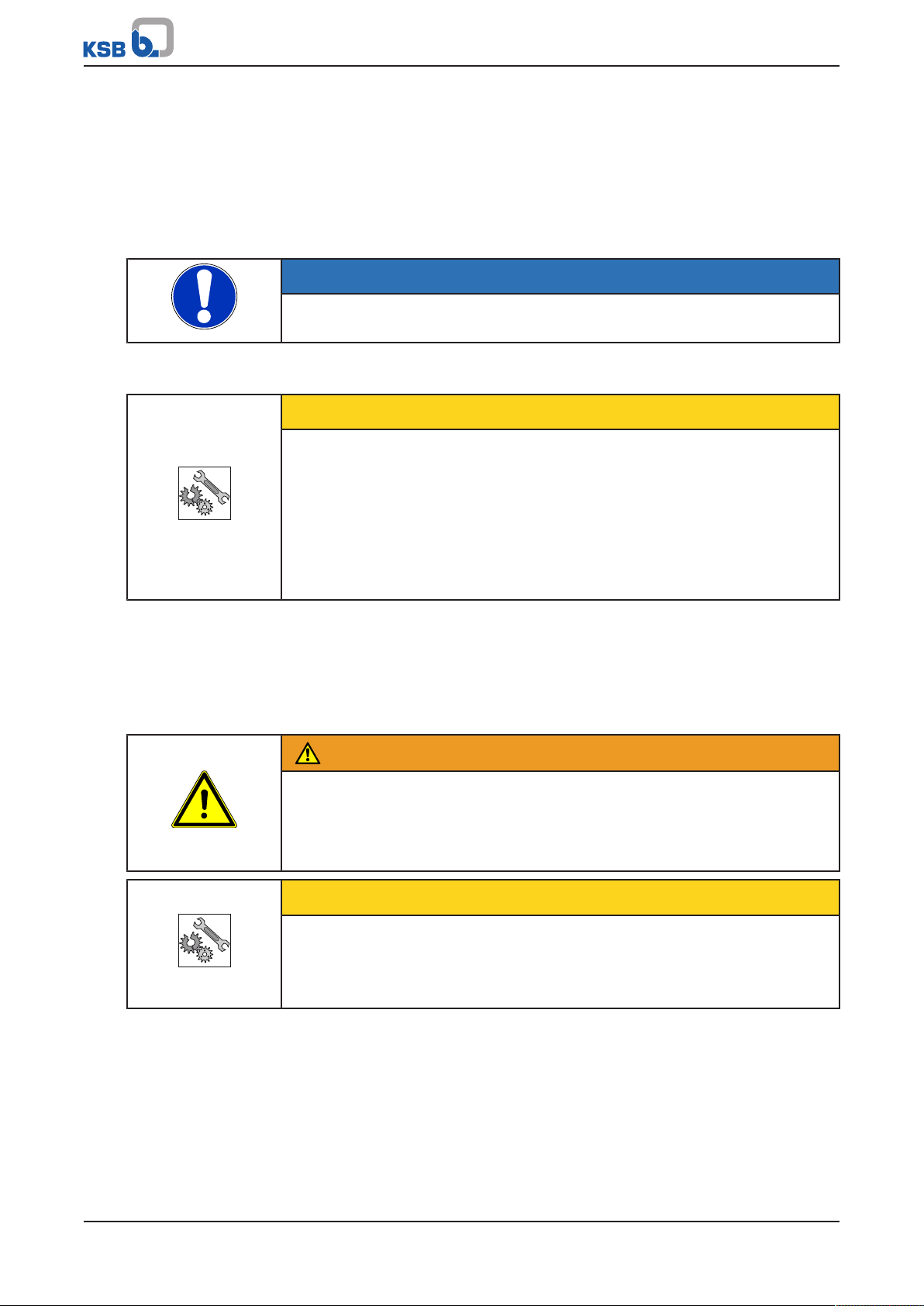
NOTE
The pump set is supplied by the manufacturer/supplier in packaging which largely
prevents sagging or other damage during transport and/or storage.
3.2 Transport
CAUTION
Improper pump transport
Damage to the pump!
▷ Always transport the pump/pump set in the specified position.
▷ Never suspend the pump (set) from the power cable.
▷ Prevent the pump (set) from getting knocked or dropped.
▷ Always secure a pump set in upright position against tipping over.
▷ Wear personal protective equipment.
Use lifting equipment which is suitable for the weight of the pump set.
Make sure that the power cable is not kinked or damaged during transport.
3.3 Storage/preservation
If commissioning is to take place some time after delivery, we recommend that the
following measures be taken:
WARNING
Pump set tilting or rolling off
Risk of personal injury!
▷ Always secure vertically positioned pump sets against tipping over.
▷ Always secure horizontally positioned pump sets against rolling off.
CAUTION
Damage during storage due to frost, humidity, dirt, UV radiation or vermin
Corrosion/contamination of the pump!
▷ Store the pump (set) in a dry, dark, frost-proof room not exposed to sunlight
where the atmospheric humidity is as constant as possible.
Store the pump as follows:
▪ In a dry environment
▪ Protected against direct sunlight and heat
▪ Protected against dirt and dust
▪ Protected against freezing
▪ Protected against vermin
Further information on storing the pump set after it has been in use
(ðSection6.4,Page21) .
Ixo N
11 of 32
Page 12
3 Transport/Temporary Storage/Disposal
3.4 Return to supplier
1. Drain the pump as per operating instructions.
2. Flush and clean the pump, particularly if it has been used for handling noxious,
explosive, hot or other hazardous fluids.
3. If the pump has handled fluids whose residues could lead to corrosion damage
in the presence of atmospheric humidity or could ignite upon contact with
oxygen also neutralise the pump and blow through with anhydrous inert gas to
ensure drying.
4. Always complete and enclose a certificate of decontamination when returning
the pump.
Indicate any safety measures and decontamination measures taken.
(ðSection11,Page30)
NOTE
If required, a blank certificate of decontamination can be downloaded from the
following web site: www.ksb.com/certificate_of_decontamination
3.5 Disposal
WARNING
Fluids, consumables and supplies posing a health hazard
Hazard to persons and the environment!
▷ Collect and dispose of any preservatives, flushing liquids and fluid residues.
▷ Wear safety clothing and a protective mask, if required.
▷ Observe all legal regulations on the disposal of fluids posing a health hazard.
1. Dismantle the product.
Collect greases and other lubricants during dismantling.
2. Separate and sort the materials, e.g. by:
- Metals
- Plastics
- Electronic waste
- Greases and other lubricants
3. Dispose of materials in accordance with local regulations or in another
controlled manner.
Electrical or electronic equipment marked with the adjacent symbol must not be
disposed of in household waste at the end of its service life.
Contact your local waste disposal partner for returns.
If the used electrical or electronic equipment contains personal data, the user is
responsible for deleting it before the equipment is returned.
12 of 32
Ixo N
Page 13
4 Description
IXO N 45 E
Q min/max 1/4,5 m3/h
0115000022
H max/min 41,5/16 m IP 68 1-20
n 2900/min
220-240V~50Hz(20uf 450V) cosø 0,95
4,1 A
XXXXXXXX
35°C S1 l.cl. F 15,5 kg
0,55 kW (0,75 Hp) S.F.
KSB SAS, 4, allée des Barbanniers 92230 GENNEVILLIERS
2014
1
6
78
910
11
12
13
14
15
16
2
3
4
5
4 Description
4.1 General description
Submersible borehole pump
Pump for handling clean water without suspended solids.
4.2 Designation
Example: Ixo N 45 E
Table3: Designation key
Code Description
Ixo Type series
N New generation
4 Number of stages
5 Maximum flow rate [m³/h]
E Single-phase AC motor
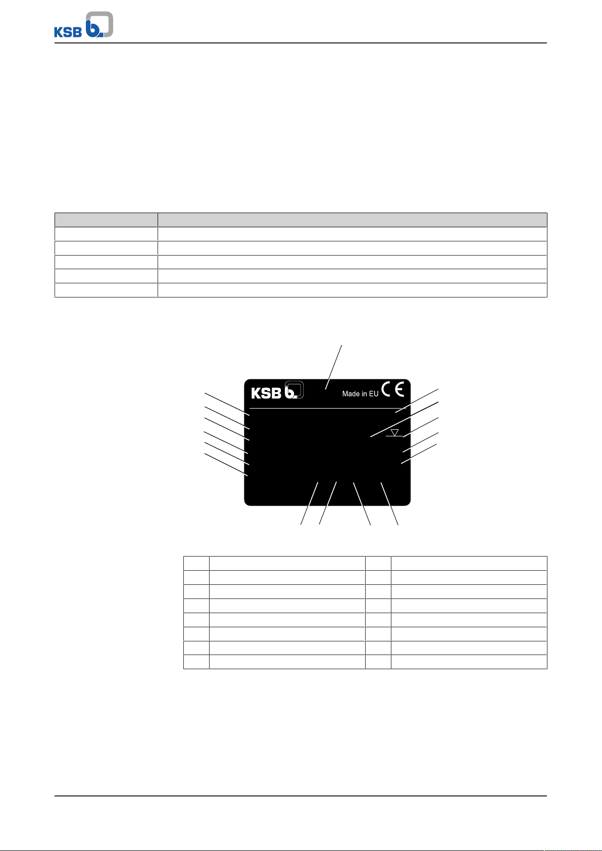
4.3 Name plate
Fig.1: Name plate (example)
1 Year of construction 2 Series number
3 Enclosure 4 Maximum immersion depth
5 Rated speed 6 Cosine phi
7 Weight 8 Thermal class
9 Mode of operation 10 Maximum fluid temperature
11 Nominal current 12 Voltage, frequency
13 Power output (P2) 14 Range of heads
15 Range of flow rates 16 Type series, number of stages
4.4 Design details
Design
▪ Centrifugal pump
▪ Close-coupled design
▪ Multistage
Ixo N
13 of 32
Page 14

4 Description
▪ For fully or partly submerged operation (min. immersion depth 0.1m)
▪ Low-level inlet
▪ Suction strainer with a maximum mesh width of 2mm
Drive
Jacket-cooled single-phase AC motor:
▪ Thermal overload protection
▪ 230V, 50Hz
▪ IP68 enclosure
▪ Capacitor installed
▪ Motor power cable (H07 RNF) 23m with mains plug
Jacket-cooled three-phase motor:
▪ 400V, 50Hz
▪ IP68 enclosure
▪ Motor power cable 23m
Bearings
▪ Deep groove ball bearings
▪ Grease-lubricated for life
Shaft seal
▪ Double shaft seal with oil reservoir fitted in between
4.5 Configuration and function
The fluid enters the pump via the suction casing. It is accelerated outward by the
rotating impellers. In the flow passage of the diffusers and the pump casing the
kinetic energy of the fluid is converted into pressure energy. The fluid is pumped to
the discharge side, where it leaves the pump. At the rear side of the impeller, the
motor shaft enters the casing via the bearing cover. The shaft passage is sealed by a
double mechanical seal. The shaft is supported by rolling element bearings.
4.6 Scope of supply
▪ Multistage submersible borehole pump
▪ Single-phase AC motor
(with integrated thermal protection, 230V, 50Hz, IP68, built-in capacitor, 23metre motor power cable with mains plug)
or
▪ Three-phase motor
(400V, 50Hz, IP68, 23-metre motor power cable)
14 of 32
Ixo N
Page 15
4 Description
G 1 1/4
H
Ø 133
ISO 228
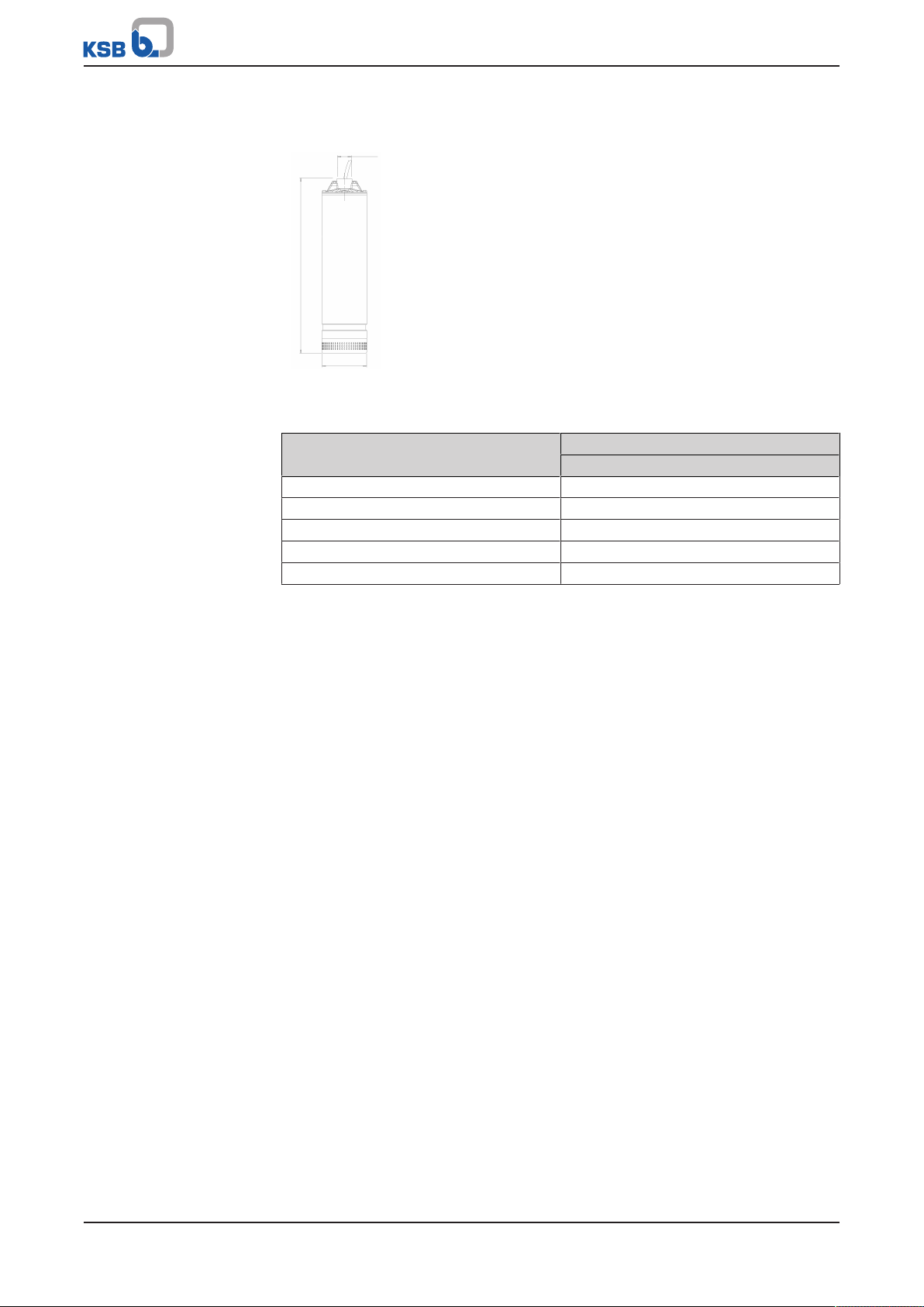
4.7 Ixo N
Fig.2: Ixo N pump
Table4: Dimensions
Size H
[mm]
Ixo N 45 E/D 504
Ixo N 55 E/D 553
Ixo N 65 E/D 577
Ixo N 48 E/D 529
Ixo N 58 E/D 553
Ixo N
15 of 32
Page 16
5 Installation at Site
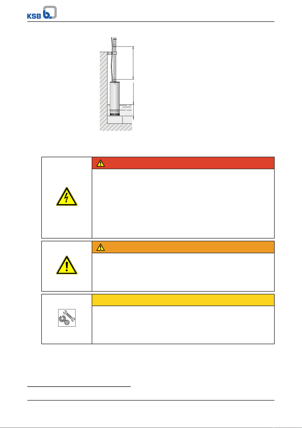
≥ 0,5 m
≤ 20 m
≥140 mm
31
4 65
7
2
5 Installation at Site
5.1 Installing the pump set
CAUTION
Incorrect installation
Damage to the machine
▷ The pump set must always be installed in a vertical position.
▷ Never suspend the pump set by the power cable.
NOTE
We recommend securing the suspended pump set with a safety rope or chain made
of indestructible material at all times. If a plastic pipe or hose is used as a discharge
line, the safety rope must be used for lowering, fastening and pulling up the pump
set.
Observe the following when selecting a place of installation:
▪ Never install the pump set too close to the inner walls of the tank / rainwater
storage tank.
▪ Observe the installation heights of max. 20m.
▪ To prevent intake of sand install the pump set at a distance of at least 0.5m from
the bottom of the well.
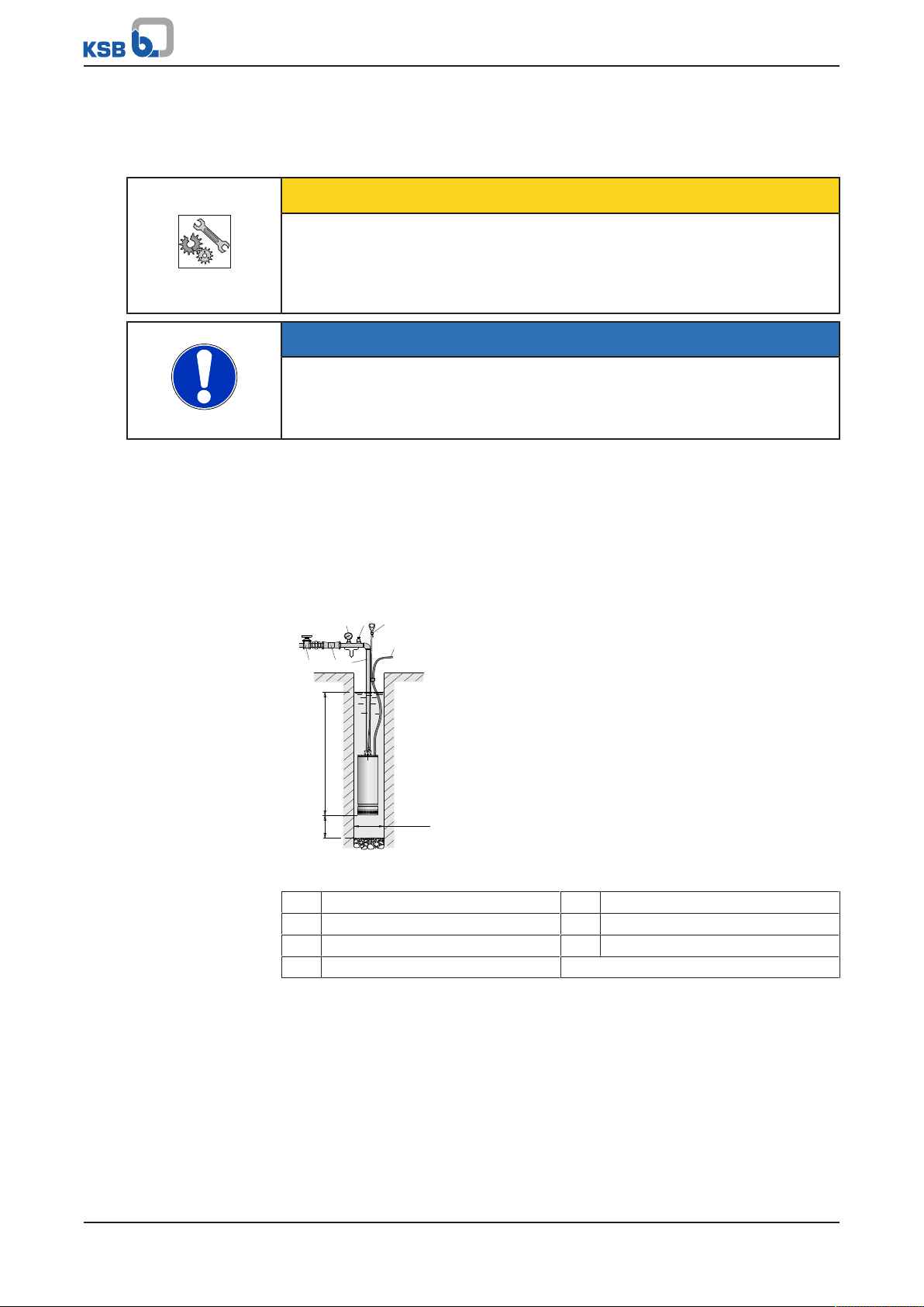
The pump set can be installed as follows:
16 of 32
Fig.3: Pump set suspended from the discharge line
1 Pressure gauge 2 Vent valve
3 Safety rope 4 Gate valve
5 Lift check valve 6 Discharge line
7 Power cable
Ixo N
Page 17
5 Installation at Site
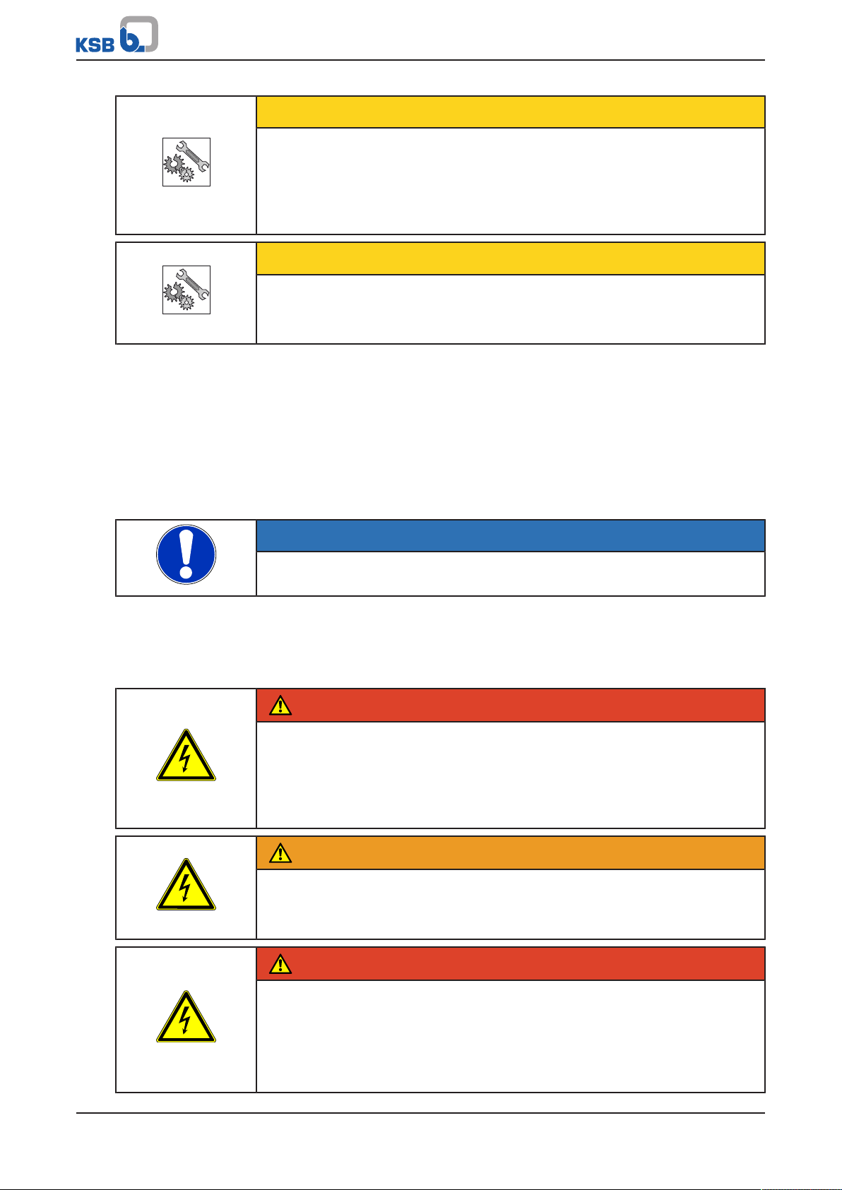
≥ 100 mm
≥ 2 m
Fig.4: Pump set sitting on the floor in a vertical position
5.2 Connecting the piping
DANGER
Using damaged power cables in the tank / rainwater storage tank
Electric shock!
▷ Do not kink the power cable. Observe the minimum bending radius1) of the
cable. Do not drag the cable over sharp edges.
▷ Fasten the power cable to the riser or piping every 3m with suitable fasteners
(e.g. cable clips, sleeves). (Provide sufficient slack between the fasteners to
prevent the power cable from any tension caused by the expansion of the pipe
under load.)
▷ Do not use any tools, equipment or accessories with sharp edges (e.g. sharp-
edged pipe sockets) for the installation.
WARNING
Persons falling into unsecured tanks / rainwater storage tanks
Risk of injury!
▷ Always secure open tanks / rainwater storage tanks during the entire
installation procedure to prevent persons from falling in.
▷ Suitably fence off the work area.
CAUTION
Pump set falling into the tank / rainwater storage tank
Damage to the pump set!
▷ Secure the pump set during the entire installation procedure.
▷ Dimension any securing devices (supporting clamps, supports, etc.) so that they
can carry all weights during the installation.
1) See cable manufacturer's documentation or DINVDE0298-3.
Ixo N
17 of 32
Page 18
5 Installation at Site
CAUTION
Unsuitable pipeline
Faulty operation of the pump!
▷ If using plastic pipelines, make sure they are designed to withstand the pump
pressure.
▷ Do not kink the plastic pipeline.
CAUTION
Incorrect assembly
Damage to the pump set!
▷ Never hold or transport the pump set by its power cable.
Installation information
▪ The pump sets can be connected to pipelines with a G 11/4 thread (DN32).
▪ The inside diameter of the riser must not be smaller than the pump connection
with a thread of G 11/4 (DN32).
▪ Position the pump sets vertically with the discharge nozzle on top.
▪ The pump set can be supported by the metal discharge line. For this purpose,
firmly tighten the threaded connections to prevent them from loosening.
NOTE
Using a discharge line of a larger diameter is recommended in the case of very high
static heads or very long pipelines in order to prevent pressure losses.
1. Install the pipelines in accordance with the manufacturer's documentation.
2. Lower the pump set into the tank / rainwater storage tank.
5.3 Electrical connection
DANGER
Electrical connection work by unqualified personnel
Danger of death from electric shock!
▷ Always have the electrical connections installed by a trained and qualified
electrician.
▷ Observe regulations IEC60364.
WARNING
Incorrect connection to the mains
Damage to the mains network, short circuit!
▷ Observe the technical specifications of the local energy supply companies.
18 of 32
DANGER
Connection of damaged power cables
Danger of death from electric shock!
▷ Check the power cables for damage before connecting them.
▷ Never connect damaged power cables.
▷ Replace damaged power cables.
Ixo N
Page 19
5 Installation at Site
grigio
grey
grau
gris
gris
grå
grijs
γκρι
серый
M
1
marrone
brown
braun
marron
marrón
rödbrun
bruin
KáöÝ
êîðè÷
verde/giallo
green/yellow
grün/gelb
vert/jaune
verde/gualdo
grön/gul
groen/geel
ÐсЬуйнп/кЯфсйнп
æåë./æåëò
blu
blue
blau
bleu
azul
blå
blauw
μπλε
синий
4.67.380/1
nero
black
schwarz
noir
negro
svart
zwart
μαύρο
черный
rosso
red
rot
rouge
rojo
röd
rood
κόκκινο
красный
bianco
white
weiss
blanc
blanco
vit
wit
λευκό
белый
白 色
≥ 1,5 kW
CAUTION
Galvanic corrosion using the pump set in water containing chloride (or in salt
water)
Damage to the pump set!
▷ Connect the pump set to earth, also if using non-metal pipelines and safety
ropes.
▪ Install a device for switching off each phase conductor at the mains (switch).
Provide a minimum opening distance of 3mm for the contacts.
▪ If the water level cannot be checked visually, a float switch or another protective
device must be installed to prevent dry running of the pump set and to set the
water levels for automatic start-up/stop of the pump set.
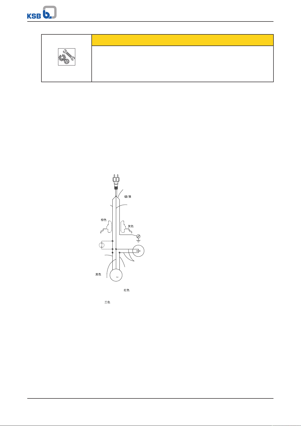
▪ Pump sets with single-phase AC motor (IxoNE)
These pump sets are fitted with a capacitor, thermal protection plug and,
optionally, with a float switch. Connect the plug to a socket with earth contact.
Excessive temperatures lead to the motor cutting out. When the winding
temperature decreases again (after 2 to 4 minutes), the thermal switch starts up
the motor again.
▪ Pump sets with three-phase motor (Ixo N D)
For these pump sets install a motor protection switch (curve type D) in the
control cabinet. Observe the current requirement indicated on the name plate.
Fig.5: Circuit diagram
ü Check the available mains voltage against the data on the name plate.
ü The mains is protected by a residual current device of ≤30mA.
1. Plug the mains plug into the mains socket.
Ixo N
19 of 32
Page 20
6 Commissioning/Start-up/Shutdown
6 Commissioning/Start-up/Shutdown
6.1 Commissioning/Start-up
6.1.1 Starting up and stopping
CAUTION
Prolonged operation of the pump set against a closed shut-off element
Damage to the pump set!
▷ Never operate the pump set against a closed shut-off element for more than
5minutes.
CAUTION
Insufficient lubrication of the mechanical seal
Damage to the mechanical seal!
▷ Never operate the pump set in dry condition, not even for testing.
NOTE
In the event of any malfunctions immediately disconnect the pump set from the
mains.
The pump set starts pumping as soon as it is connected to the power supply. When
the power supply is interrupted, the pump set stops.
ü The minimum immersion depth of 100mm has been observed.
1. For three-phase motors check the direction of rotation.
To do so, start the pump set (with the shut-off element in any open position)
and check the pressure (with a pressure gauge) or the flow rate (visually). Then
disconnect the pump set from the power supply. Interchange two phase
connections in the control cabinet. Re-start the pump set. Check the pressure
and flow rate again. The correct direction of rotation results in a significantly
higher pressure and larger flow rate.
2. Verify that the pump set operates within its operating range and that the
power intake indicated on the name plate is not exceeded. If necessary, adjust
the shut-off element in the discharge line or the pressure switches (if any).
6.2 Operating data
Table5: Operating properties
Characteristic Value
Flow rate Q [m3/h] ≤8
Q [l/s] ≤2,22
Head H [m] ≤65
Fluid temperature T [°C] ≥+5
≤+35
20 of 32
6.3 Operating limits
▪ Only suitable for vertical operation.
▪ Maximum immersion depth: 20m
▪ Maximum particle size: 2mm
▪ Maximum number of start-ups/hour: 30
Ixo N
Page 21

6 Commissioning/Start-up/Shutdown
6.4 Taking the pump set out of service
If the pump set is not in service for a prolonged period of time, taking the following
measures is recommended.
1. Remove the pump set from the tank / rainwater storage tank.
2. Drain the pipelines and the pump set.
3. Store the pump set properly. (ðSection3.3,Page11)
Ixo N
21 of 32
Page 22
7 Servicing/Maintenance
7 Servicing/Maintenance
7.1 Safety regulations
DANGER
Power supply not disconnected
Danger to life!
▷ Pull the mains plug and secure the pump against unintentional start-up.
DANGER
Work on the pump set by unqualified personnel
Danger of death from electric shock!
▷ Have pump components modified and dismantled by authorised personnel
only.
WARNING
Insufficient stability
Risk of crushing hands and feet!
▷ During assembly/dismantling, secure the pump (set)/pump parts to prevent
tilting or tipping over.
WARNING
Fluids handled, consumables and supplies posing a health hazard
Hazard to persons and the environment!
▷ Clean the pump prior to any maintenance and installation work.
▷ Make sure persons cannot come into contact with the fluid handled.
7.2 Maintenance/inspection
Clean the pump set once a month.
7.2.1 Cleaning the pump set
1. Check that the suction strainer is free from any foreign matter. Remove any
foreign matter.
2. Wipe the outer casing of the pump set with a cloth and clean water.
7.3 Ordering spare parts
Always quote the following data when ordering replacement or spare parts:
▪ Type series
▪ Size
Refer to the name plate for all data.
Also specify the following data:
▪ Quantity of spare parts
▪ Part number and description
▪ Shipping address
▪ Mode of dispatch (freight, mail, express freight, air freight)
22 of 32
Ixo N
Page 23
7 Servicing/Maintenance
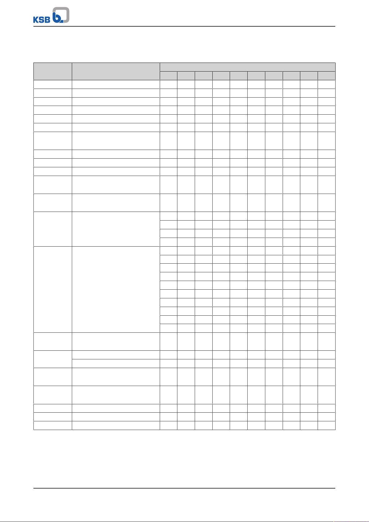
7.4 Spare parts
Table6: Available spare parts
Part No. Description Size
45 E 45 D 48 E 48 D 55 E 55 D 58 E 58 D 65 E 65 D
106 Suction-side filter ✘ ✘ ✘ ✘ ✘ ✘ ✘ ✘ ✘ ✘
109.01 Stage casing, 1st stage ✘ ✘ ✘ ✘ ✘ ✘ ✘ ✘ ✘ ✘
109.02 Stage casing 3 3 3 3 4 4 4 4 5 5
230 Impeller 4 4 4 4 5 5 5 5 6 6
321.01 Ball bearing ✘ ✘ ✘ ✘ ✘ ✘ ✘ ✘ ✘ ✘
321.02 Pump-end ball bearing ✘ ✘ ✘ ✘ ✘ ✘ ✘ ✘ ✘ ✘
99-9 Set of O-rings, complete
(412.01 - 412.13)
433.01 Mechanical seal, top ✘ ✘ ✘ ✘ ✘ ✘ ✘ ✘ ✘ ✘
433.02 Mechanical seal, bottom ✘ ✘ ✘ ✘ ✘ ✘ ✘ ✘ ✘ ✘
506 Retaining ring (506 + 50.3) ✘ ✘ ✘ ✘ ✘ ✘ ✘ ✘ ✘ ✘
525 Spacer sleeve
(525.01/02/03 + 523)
554 Washer
(554.01/02/03/04)
81-59 Motor shroud with winding - ✘ - - - ✘ - - - -
818 Rotor - ✘ - - - - - - - -
824 Cable, length 23m
(829.01/02/03+733.02/03)
837 Capacitor 20µF ✘ - - - ✘ - - - - -
Capacitor 25µF - - ✘ - - - ✘ - ✘ -
81-45 Float switch
(81-45+733.01/04/05+554.04)
99-20 Set of bolts/screws
(900.01 - 900.11)
921 Shaft nut 2 2 2 2 2 2 2 2 2 2
931 Lock washer ✘ ✘ ✘ ✘ ✘ ✘ ✘ ✘ ✘ ✘
932.01/02 Circlip ✘ ✘ ✘ ✘ ✘ ✘ ✘ ✘ ✘ ✘
✘ ✘ ✘ ✘ ✘ ✘ ✘ ✘ ✘ ✘
✘ ✘ ✘ ✘ ✘ ✘ ✘ ✘ ✘ ✘
✘ ✘ ✘ ✘ ✘ ✘ ✘ ✘ ✘ ✘
✘ - - - ✘ - - - - -
- - - ✘ - - - ✘ - ✘
- - ✘ - - - ✘ - ✘ -
✘ - - - - - - - - - - - ✘ - - - - - -
- - ✘ - - - - - - -
- - - - - ✘ - - - -
- - - - ✘ - - - - - - - - - - - ✘ - - - - - - - ✘ - - - - - - - - - - - ✘
- - - - - - - - ✘ -
✘ ✘ ✘ ✘ ✘ ✘ ✘ ✘ ✘ ✘
✘ ✘ ✘ ✘ ✘ ✘ ✘ ✘ ✘ ✘
✘ ✘ ✘ ✘ ✘ ✘ ✘ ✘ ✘ ✘
Ixo N
23 of 32
Page 24
8 Trouble-shooting
8 Trouble-shooting
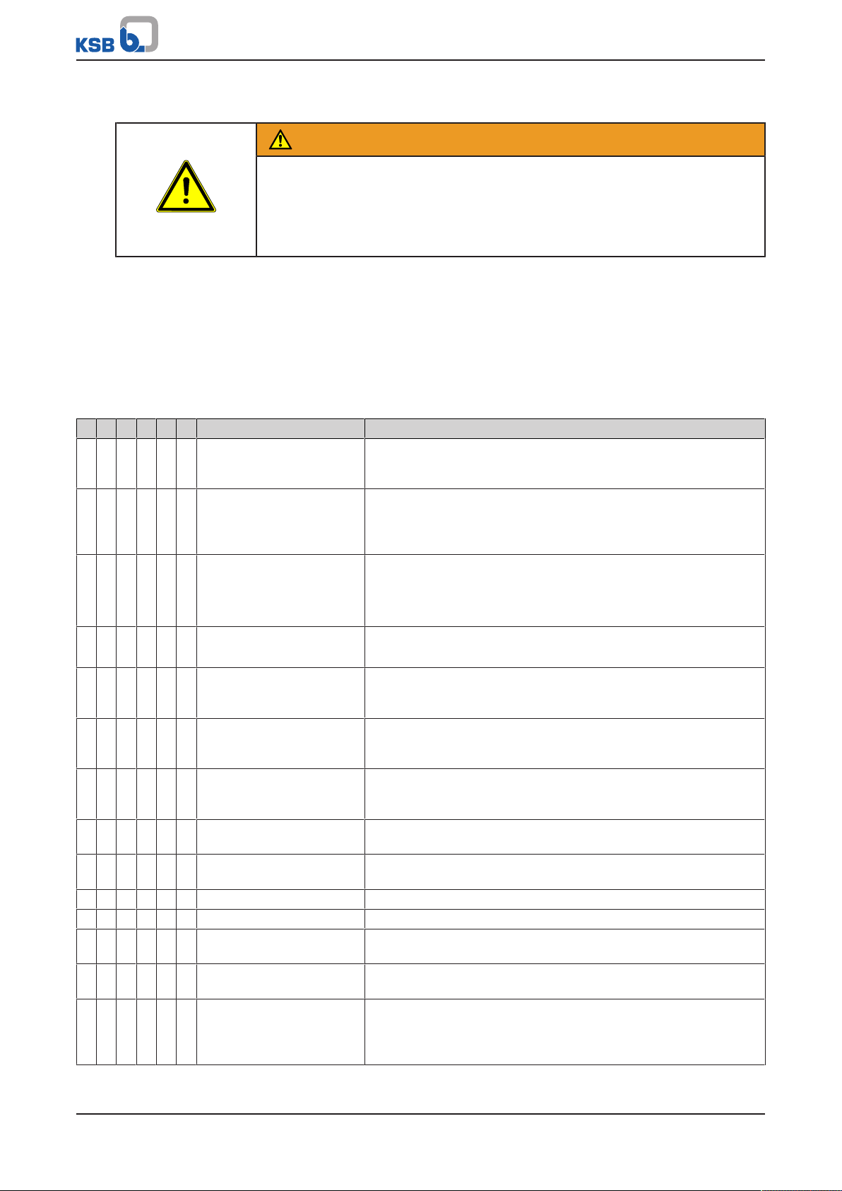
WARNING
Improper work to remedy faults
Risk of injury!
▷ For any work performed to remedy faults, observe the relevant information
given in this instruction manual and/or in the product literature provided by the
accessories manufacturer.
A Motor not starting up
B Pump set blocked
C Pump set running but not pumping any fluid
D Flow rate too low
E Unusual noises and vibrations at the pump set
F Leakage at the shaft seal
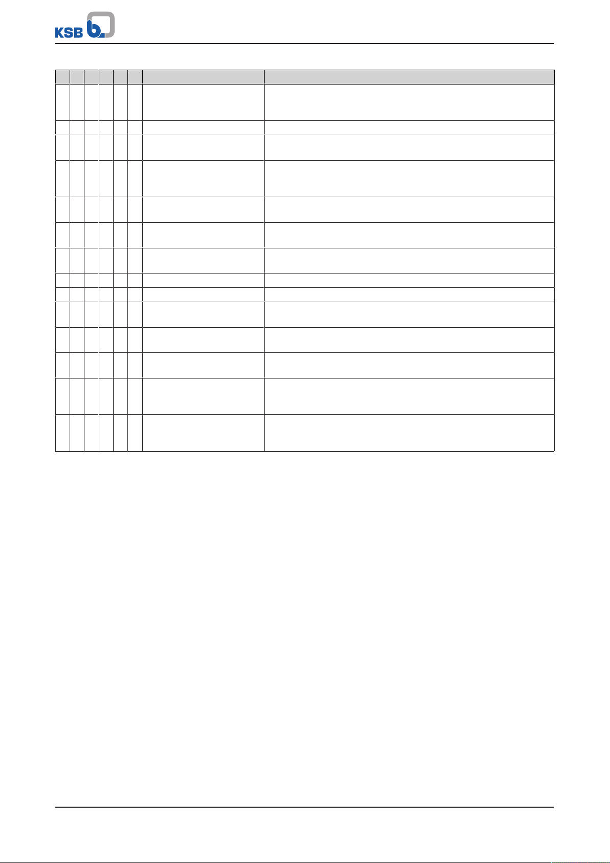
Table7: Trouble-shooting
A B C D E F Possible cause Remedy
✘ - - - - - Incorrect supply voltage Verify the existing voltage and frequency against the data on the
name plate of the motor. Make sure that the cable cross-section of
any extension cable used meets the requirements of the motor.
✘ - - - - - Incorrect electrical
installation
✘ - - - - - Motor protection device
(protective switch) has
tripped.
✘ - - - - - Fuses defective or tripped Replace fuses.
✘ - - - - - Shaft blocked Remove the cause of blockage. To do so, dismantle the pump
✘ - - - - - If all of the above remedies
have been checked, the
motor might be defective.
- ✘ - - - - Solid particles in the pump
chamber block the rotor
unit.
- ✘ - - - - Bearing seized Replace defective bearings. If necessary, involve an authorised
- - ✘ - - - Check if valves are clogged,
blocked or closed.
- - ✘ - - - Gate valve closed Open the gate valve.
- - ✘ - - - Pump strainer clogged Remove the suction strainer to clean or replace it as required.
- - ✘ - - - Pump not submerged in
the water (dry running)
- - ✘ - - - Wrong direction of
rotation
- - - ✘ - - Pipelines and valves with
too small a nominal
diameter are causing
excessive losses.
Check the connection to the power supply. Correct it, if necessary.
Check that the protective switch has been set correctly (observe
the data on the name plate). Check that the motor cable is
properly connected to the control cabinet.
Check power supply.
Check whether the motor shaft can be easily rotated. Verify the
correct setting of the motor protection switch (observe the data
on the name plate of the motor).
Check power supply. Check if motor protection switch has tripped.
casing and remove the solid particles. If necessary, involve an
authorised service partner.
Have the motor replaced or repaired by an authorised service
partner.
If possible, dismantle the pump casing and remove the solid
particles. If necessary, involve an authorised service partner.
service partner.
Check lift check valves and other check valves. Replace them, if
necessary.
Check and correct the installation of the pump set.
Have the motor connection (cable connection) checked by
specialist personnel.
Use pipelines and valves in accordance with the corresponding
recommendations for use.
24 of 32
Ixo N
Page 25
8 Trouble-shooting
A B C D E F Possible cause Remedy
- - - ✘ - - Solid particles have
clogged impellers or
diffusers.
- - - ✘ - - Impellers damaged Remove the pump and contact an authorised service partner.
- - - ✘ - - Impellers and diffusers
worn.
- - - ✘ - - Water level in the well has
dropped.
- - - ✘ - - Wrong direction of
rotation
- - - ✘ - - Leakage in the discharge
line
- - - ✘ - - Large percentage of air in
the water
- - - - ✘ - Unbalance of the rotor unit Check that the impeller is free from solid particles.
- - - - ✘ - Motor bearing defective Replace the bearing.
- - - - ✘ - Pump and piping not
fastened
- - - - ✘ - Flow rate too large for
existing pipeline.
- - - - ✘ - Power supply fault Verify the existing voltage and frequency against the data on the
- - - - - ✘ Defect caused by dry
running or by gluing
together of contact faces.
- - - - - ✘ Contact faces damaged by
abrasive particles, score
marks, rubbing marks.
Remove the pump and contact an authorised service partner.
Remove the pump and contact an authorised service partner.
Increase the immersion depth. Reduce the flow rate by closing a
shut-off valve in the discharge line. Water consumption exceeds
well capacity. Selected pump too large for the well capacity
Have the motor connection (cable connection) checked by
specialist personnel.
Check the entire pipeline. Detect and seal the leaking areas or
replace the pipeline. Involve specialist personnel as required.
Contact an authorised service partner.
Fasten the pump and piping.
Use pipelines of a larger diameter or reduce the flow rate.
name plate.
Make sure that the pump is completely primed and vented.
Install a suction-side filter. If necessary, also select a special shaft
seal for the fluid handled.
Ixo N
25 of 32
Page 26
9 Related Documents
9 Related Documents
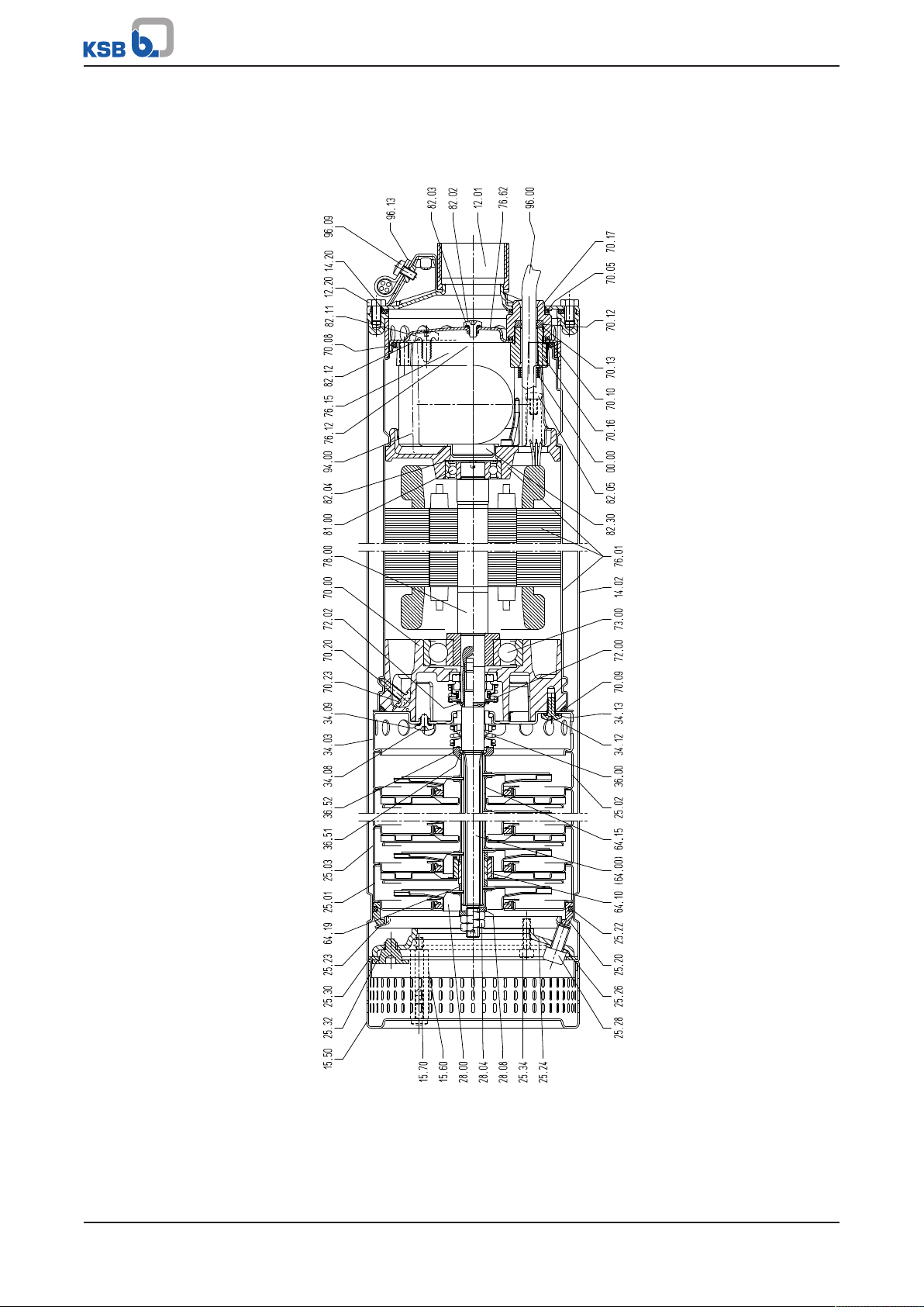
9.1 General assembly drawing
Fig.6: General assembly drawing
26 of 32
Ixo N
Page 27
9 Related Documents
(900.10)
(829.03)
(412.08)
81.6
837
916.03
81.59
916.02
160.02
(412.07)
(412.10)
(554.04)
829.04
(733.01)
(412.13)
931
(733.02)
321.01
(829.01)
(554.03)
(900.08)
(412.12)
818
(829.02)
312.02
812
(412.09)
433.01
(932.02)
160.01
(412.05)
916.01
(412.06)
(900.05)
433.02
(506)
(50.3)
(525.02)
230
(525.02)
109.02
(525.02)
230
(412.11)
(900.06)
109.02
(525.03)
(523)
(525.03)
230
109.01
(525.02)
(554.02)
921
(412.04)
474
(525.01)
(932.01)
(900.04)
(554.01)
(900.03)
45.4
106
(900.02)
824
81-45
(900.01)
(733.05)
(900.11)
107
(412.03)
81.78
Plan 584 347-00 ind A
(733.04)
(733.03)
(900.09)
(900.07)
59.7
(412.02)
(412.01)
506
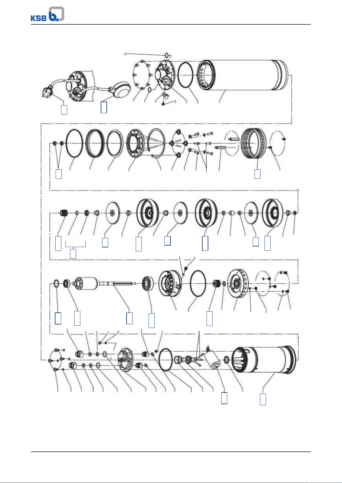
9.2 Exploded view
Fig.7: Exploded view
Ixo N
27 of 32
Page 28

9 Related Documents
28 of 32
Ixo N
Page 29

10 EU Declaration of Conformity
10 EU Declaration of Conformity
Manufacturer: KSB S.A.S.
128, rue Carnot,
59320 Sequedin (France)
The manufacturer herewith declares that the product:
IxoN
Serial number: xx15000000 to xx19999999
▪ is in conformity with the provisions of the following Directives as amended from time to time:
– Pump set: EC Machinery Directive 2006/42/EC
– Pump set: Electromagnetic Compatibility Directive 2014/30/EU
The manufacturer also declares that
▪ the following harmonised international standards have been applied:
– ISO 12100
– EN 809
– EN 60034-1, EN 60034-5/A1
– EN 60335-1/A1, EN 60335-2-41
Person authorised to compile the technical file:
Christian Appel
Head of Product Management Well and Ring-section Pumps
KSB SE & Co. KGaA
Johann-Klein-Straße 9
67227 Frankenthal (Germany)
The EU Declaration of Conformity was issued in/on:
Frankenthal, 1 September 2018
Joachim Schullerer
Head of Product Development Pump Systems and Drives
KSB SE & Co. KGaA
Johann-Klein-Straße 9
67227 Frankenthal
Ixo N
29 of 32
Page 30
11 Certificate of Decontamination
11 Certificate of Decontamination
Type: ................................................................................................................................
Order number/
Order item number2): ................................................................................................................................
Delivery date: ................................................................................................................................
Field of application: ................................................................................................................................
Fluid handled2): ................................................................................................................................
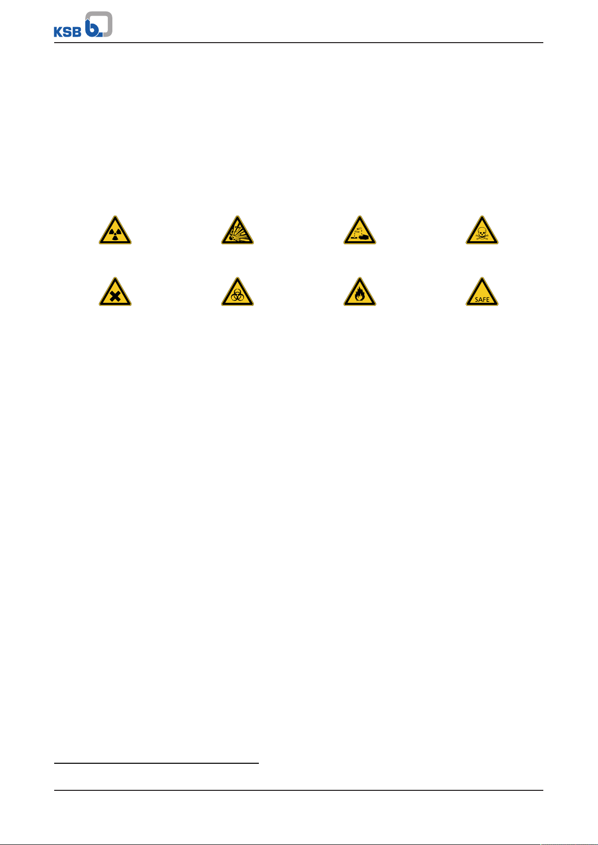
Please tick where applicable2):
Radioactive Explosive Corrosive Toxic
Harmful Bio-hazardous Highly flammable Safe
Reason for return2): ................................................................................................................................
Comments: ................................................................................................................................
................................................................................................................................
The product/accessories have been carefully drained, cleaned and decontaminated inside and outside prior to dispatch/
placing at your disposal.
We herewith declare that this product is free from hazardous chemicals, biological and radioactive substances.
For mag-drive pumps, the inner rotor unit (impeller, casing cover, bearing ring carrier, plain bearing, inner rotor) has been
removed from the pump and cleaned. In cases of containment shroud leakage, the outer rotor, bearing bracket lantern,
leakage barrier and bearing bracket or adapter have also been cleaned.
For canned motor pumps, the rotor and plain bearing have been removed from the pump for cleaning. In cases of leakage at
the stator can, the stator space has been examined for fluid leakage; if fluid handled has penetrated the stator space, it has
been removed.
No special safety precautions are required for further handling.
The following safety precautions are required for flushing fluids, fluid residues and disposal:
...............................................................................................................................................................
...............................................................................................................................................................
We confirm that the above data and information are correct and complete and that dispatch is effected in accordance with the
relevant legal provisions.
.................................................................... ....................................................... .......................................................
Place, date and signature Address Company stamp
2) Required fields
30 of 32
Ixo N
Page 31

Index
Index
B
Bearings14
C
Certificate of decontamination30
Cleaning22
D
Design13
Designation13
Disposal12
Drive14
E
Event of damage6
Ordering spare parts22
F
Faults
Causes and remedies24
Fields of application8
I
Intended use8
K
Key to safety symbols/markings6
O
Operating properties20
R
Return to supplier12
S
Safety8
Safety awareness9
Shaft seal14
Spare part
Ordering spare parts22
Spare parts23
T
Transport11
W
Warnings6
Warranty claims6
Ixo N
31 of 32
Page 32

KSB SE & Co. KGaA
Johann-Klein-Straße 9 • 67227 Frankenthal (Germany)
Tel. +49 6233 86-0
www.ksb.com
2142.8/03-EN
 Loading...