

KSB Hya-Solo DV Series Operating Manual
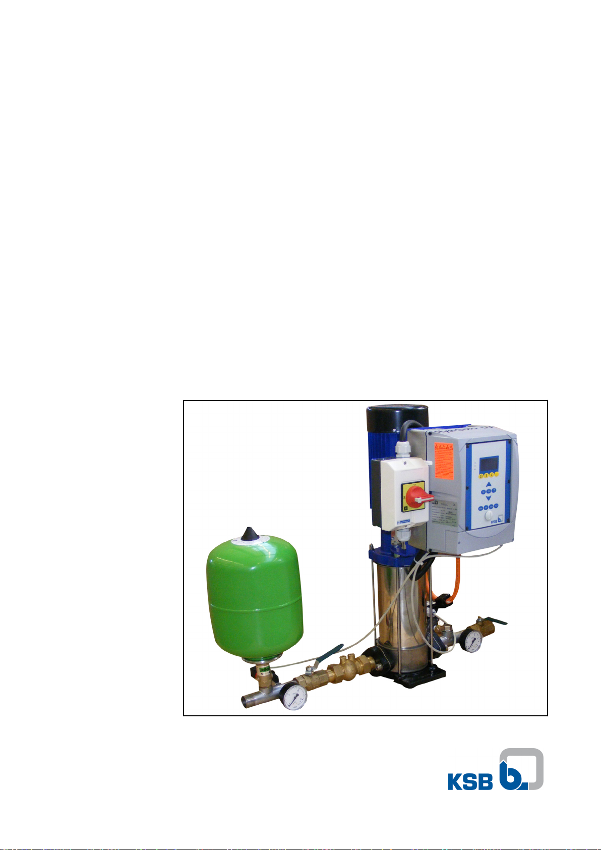
Pressure Booster System
Hya®-Solo DV
from series S-V/1
Installation/Operating
Manual

Your contact:
Tel: 01474 832498
Email: technique1988@gmail.com
Web: www.techniquetergravesend.co.uk
Legal information/Copyright
Installation/Operating Manual Hya®-Solo DV
Original operating manual
KSB Aktiengesellschaft Frankenthal
All rights reserved. Contents provided herein must neither be distributed, copied, reproduced, edited
or processed for any other purpose, nor otherwise transmitted, published or made available to a third
party without KSB´s express written consent.
Subject to technical modification without prior notice.
© KSB Aktiengesellschaft Frankenthal 22.4.2010

Contents
Contents
Glossary ................................................................................................ 5
1 General ................................................................................................ 6
1.1 Principles .......................................................................................................... 6
1.2 Installation of partly completed machinery .................................................. 6
1.3 Target group ................................................................................................... 6
1.4 Other applicable documents .......................................................................... 6
1.5 Symbols ............................................................................................................ 6
2 Safety ................................................................................................... 7
2.1 Key to safety symbols/markings ..................................................................... 7
3 Software Changes ............................................................................. 10
4 Transport/Temporary Storage/Disposal ........................................... 11
4.1 As-delivered condition .................................................................................. 11
4.2 Transport ....................................................................................................... 11
4.3 Storage/Preservation ..................................................................................... 11
4.4 Return to supplier ........................................................................................ 12
4.5 Disposal of pressure booster system ............................................................ 12
5 Description ........................................................................................ 13
5.1 General description ....................................................................................... 13
5.2 Designation ................................................................................................... 13
5.3 Name plate .................................................................................................... 13
5.4 Design details ................................................................................................ 13
5.5 Configuration and function ......................................................................... 14
5.6 Noise characteristics ...................................................................................... 15
5.7 Scope of supply ............................................................................................. 15
5.8 Dimensions and weights ............................................................................... 15
5.9 Terminal wiring diagram .............................................................................. 15
6 Installation at Site ............................................................................. 21
6.1 Installation to DIN 1988 ................................................................................ 21
6.2 Checks to be carried out prior to installation ............................................. 21
6.3 Installing the pressure booster system ......................................................... 21
6.4 Installing the piping ...................................................................................... 22
6.5 Installing unpressurised inlet tanks .............................................................. 23
6.6 Fitting the dry running protection device ................................................... 23
6.7 Connection to power supply ........................................................................ 24
7 Commissioning/Start-up/Shutdown ................................................. 26
7.1 Commissioning/start-up ................................................................................ 26
7.2 Switching on the pressure booster system .................................................. 27
Hya®-Solo DV
3 of 56

Contents
7.3 Check list for commissioning/start-up .......................................................... 27
7.4 Shutdown ...................................................................................................... 28
8 Operating the Pressure Booster System ........................................... 29
8.1 Control panel functions ................................................................................ 29
8.2 Menu structure .............................................................................................. 32
8.3 Access levels ................................................................................................... 33
8.4 Displaying and changing parameters .......................................................... 34
8.5 Monitoring .................................................................................................... 35
8.6 Description of parameters ............................................................................ 35
8.7 Adjusting the settings ................................................................................... 36
9 Servicing/Maintenance ...................................................................... 43
9.1 General notes/Safety regulations ................................................................. 43
9.2 Servicing/inspection ...................................................................................... 44
10 Trouble-shooting ............................................................................... 46
10.1 Hya-Solo DV ................................................................................................... 46
10.2 PumpDrive ..................................................................................................... 47
11 Related Documents ........................................................................... 49
11.1 List of components ........................................................................................ 49
12 EC Declaration of Conformity .......................................................... 51
13 Certificate of Decontamination ....................................................... 53
14 Commissioning Report ...................................................................... 54
Index .................................................................................................. 55
4 of 56
Hya®-Solo DV

Glossary
Glossary
Accumulator
The accumulator serves to compensate for
pressure losses in the piping system
downstream of the pressure booster system
which may be caused by the consumption of
small quantities of water. As a result, the
frequency of starts of the pressure booster
system is minimised.
Automatic mode
The pump is started as a function of pressure
and stopped as a function of flow.
Certificate of decontamination
A certificate of decontamination certifies that
the pressure booster system has been properly
cleaned and decontaminated to eliminate any
environmental and health hazards arising from
components in contact with the fluid handled.
Dry running protection
Dry running protection devices prevent the
pump from being operated without the fluid to
be handled, which would result in pump
damage.
Manual mode
In manual mode, the system is operated at a
selectable speed via the frequency inverter,
independently of the control unit.
Noise characteristics
The noise emission to be expected, indicated as
sound pressure level LpA in dB(A)
PumpDrive
KSB frequency inverter mounted on the pump
set.
Hya®-Solo DV
5 of 56
1 General
1 General
1.1 Principles
This manual is supplied as an integral part of the type series and variants indicated
on the front cover. It describes the proper and safe use of this equipment in all
phases of operation.
The name plate indicates the type series/size, the main operating data and the order
number. The series/serial number clearly identifies the pressure booster system and
serves as identification for all further business processes.
In the event of damage, immediately contact your nearest KSB service centre to
maintain the right to claim under warranty.
Noise characteristics (⇨ Section 5.6 Page 15)
1.2 Installation of partly completed machinery
To install partly completed machinery supplied by KSB, please refer to the subsections under Servicing/Maintenance.
1.3 Target group
This manual is aimed at the target group of trained and qualified specialist technical
personnel. (⇨ Section 2.1.3 Page 8)
1.4 Other applicable documents
Table 1: Overview of other applicable documents
Document Contents
Sub-supplier documentation Operating manuals, logic diagram and other
product literature of accessories and integrated
machinery components
1.5 Symbols
Table 2: Symbols used in this manual
Symbol Description
✓ Conditions which need to be fulfilled before proceeding with the
step-by-step instructions
⊳ Safety instructions
⇨ Result of an action
⇨ Cross-references
1.
2.
Step-by-step instructions
Note
Recommendations and important information on how to handle
the product
6 of 56
Hya®-Solo DV
!
DANGER
!
WARNING
CAUTION
!
DANGER
2 Safety
2 Safety
All the information contained in this section refers to hazardous situations.
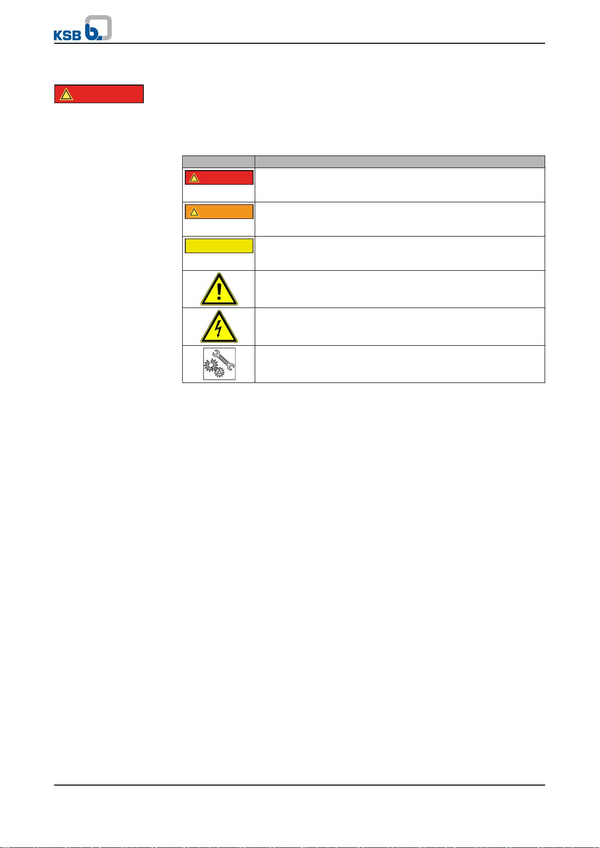
2.1 Key to safety symbols/markings
Table 3: Definition of safety symbols/markings
Symbol Description
DANGER
indicates a high-risk hazard which, if not avoided, will result in
death or serious injury.
WARNING
indicates a medium-risk hazard which, if not avoided, could result
in death or serious injury.
CAUTION
indicates a hazard which, if not avoided, could result in damage to
the machine and its functions.
General hazard
in conjunction with one of the signal words indicates a hazard
which will or could result in death or serious injury.
Electrical hazard
identifies information about protection against electrical voltage.
In conjunction with the signal word CAUTION, this symbol indicates
a hazard for the machine and its functions.
2.1.1 General
This manual contains general installation, operating and maintenance instructions
that must be observed to ensure safe operation of the pressure booster system and
prevent personal injury and damage to property.
The safety information in all sections of this manual must be complied with.
This manual must be read and completely understood by the responsible specialist
personnel/operators prior to installation and commissioning.
The contents of this manual must be available to the specialist personnel at the site
at all times.
Information attached directly to the pressure booster system must always be
complied with and be kept in a perfectly legible condition at all times. This applies
to, for example:
▪ Arrow indicating the direction of rotation
▪ Markings for connections
▪ Name plate
The operator is responsible for ensuring compliance with all local regulations which
are not taken into account in this manual.
2.1.2 Intended use
The pressure booster system must only be operated within the operating limits which
are described in the other applicable documents.
▪ Only operate pressure booster systems which are in perfect technical condition.
▪ Do not operate partially assembled pressure booster systems.
▪ The pressure booster system must only handle the fluids described in the product
literature of the respective design variant.
▪ Never operate the pressure booster system without the fluid to be handled.
Hya®-Solo DV
7 of 56

2 Safety
▪ Observe the minimum flow rates indicated in the product literature (to prevent
overheating, bearing damage, etc.).
▪ Observe the maximum flow rates indicated in the product literature (to prevent
overheating, mechanical seal damage, cavitation damage, bearing damage, etc.).
▪ Do not throttle the flow rate on the suction side of the pressure booster system
(to prevent cavitation damage).
▪ Consult the manufacturer about any use or mode of operation not described in
the product literature.
Preve n t i on of f o resee a b l e mis u s e
▪ Never exceed the permissible operating limits specified in the product literature
regarding pressure, temperature, etc..
▪ Observe all safety information and instructions in this manual.
2.1.3 Personnel qualification and training
All personnel involved must be fully qualified to install, operate, maintain and
inspect the machinery this manual refers to.
The responsibilities, competence and supervision of all personnel involved in
installation, operation, maintenance and inspection must be clearly defined by the
operator.
Deficits in knowledge must be rectified by sufficiently trained specialist personnel
training and instructing the personnel who will carry out the respective tasks. If
required, the operator can commission the manufacturer/supplier to train the
personnel.
Training on the pressure booster system must always be supervised by technical
specialist personnel.
2.1.4 Consequences and risks caused by non-compliance with these operating
instructions
▪ Non-compliance with these operating instructions will lead to forfeiture of any
and all rights to claims for damages.
▪ Non-compliance can, for example, have the following consequences:
–
Hazards to persons due to electrical, thermal, mechanical and chemical
effects and explosions
– Failure of important product functions
– Failure of prescribed maintenance and servicing practices
– Hazard to the environment due to leakage of hazardous substances
8 of 56
2.1.5 Safety awareness
In addition to the safety instructions contained in this manual and the intended use,
the following safety instructions shall be complied with:
▪ Accident prevention, health and safety regulations
▪ Explosion protection regulations
▪ Safety regulations for handling hazardous substances
▪ Applicable standards and laws
2.1.6 Safety information for the operator/user
▪ The operator shall fit contact guards for hot, cold and moving parts and check
that the guards function properly.
▪ Never remove a contact guard while the pump is running.
▪ Eliminate all electrical hazards.
Hya®-Solo DV

2 Safety
2.1.7 Safety information for maintenance, inspection and installation work
▪ Modifications or alterations of the pressure booster system are only permitted
with the manufacturer's prior consent.
▪ Use only original spare parts or parts authorised by the manufacturer. The use of
other parts can invalidate any liability of the manufacturer for resulting damage.
▪ The operator ensures that all maintenance, inspection and installation work is
performed by authorised, qualified specialist personnel who are thoroughly
familiar with the manual.
▪ Carry out work on the pressure booster system during standstill only.
▪ The pump casing must have cooled down to ambient temperature.
▪ Pump pressure must have been released and the pump must have been drained.
▪ When taking the pressure booster system out of service always adhere to the
procedure described in the manual.
▪ Decontaminate pressure booster systems which handle fluids posing a health
hazard.
▪ As soon as the work is completed, re-install and/or re-activate any safety-relevant
and protective devices. Before returning the product to service, observe all
instructions on commissioning. (⇨ Section 7.1 Page 26)
▪ Make sure the pressure booster system cannot be accessed by unauthorised
persons (e.g. children).
2.1.8 Unauthorised modes of operation
Always observe the limits stated in the product literature.
The warranty relating to the operating reliability and safety of the pressure booster
system supplied is only valid if the equipment is used in accordance with its intended
use. (⇨ Section 2.1.2 Page 7)
Hya®-Solo DV
9 of 56

3 Software Changes
3 Software Changes
The software has been specially created for this product and thoroughly tested.
It is impermissible to make any changes or additions to the software or parts of the
software. Software updates supplied by KSB are excluded from this rule.
10 of 56
Hya®-Solo DV

4 Transport/Temporary Storage/Disposal
4 Transport/Temporary Storage/Disposal
4.1 As-delivered condition
NOTE
Prior to dispatch, the pressure booster system was tested and inspected to ensure full
compliance with the specifications and should therefore be in perfect electrical and
mechanical condition upon arrival at its destination.
It is recommended that the pressure booster system be inspected for in-transit damage
immediately upon receipt. If there are any complaints or objections, the recipient and
carrier must jointly draw up a damage report.
4.2 Transport
NOTE
The pressure booster system is bolted to a pallet and wrapped in plastic foil for shipping
and temporary storage. All connecting points are capped.
DANGER
Pressure booster system tipping over
Risk of injury by falling pressure booster system!
▷ Never suspend the pressure booster system by its power cable.
▷ Observe the local accident prevention regulations.
▷ Use suitable, approved transport equipment, e.g. crane, forklift or pallet trucks.
▷ Attach the pressure booster system to crane lifting tackle as shown, or use a
forklift or pallet truck to move the pallet.
Fig. 1: Transporting the pressure booster system
✓ The pressure booster system has been checked for in-transit damage.
Make sure the transport equipment is suitable for safely carrying the indicated
1.
load.
2. Transport the pressure booster system to the place of installation.
3. Attach the pressure booster system to the lifting tackle as shown, lift it off the
pallet and dispose of the pallet.
4. Use suitable lifting equipment to lift the pressure booster system and carefully
put it down at the place of installation.
4.3 Storage/Preservation
If commissioning is to take place some time after delivery, we recommend that the
following measures be taken when storing the pressure booster system:
Hya®-Solo DV
11 of 56

4 Transport/Temporary Storage/Disposal
CAUTION
Damage during storage by frost, moisture, dirt, UV radiation or vermin
Corrosion/contamination of pressure boosting system!
▷ Store the pressure booster system in a frost-proof room. Do not store the unit
outdoors.
CAUTION
Wet, contaminated or damaged openings and connections
Leakage or damage of the pressure booster system!
▷ Only open the openings of the pressure booster system at the time of
installation.
Store the pressure booster system in a dry, protected room where the atmospheric
humidity is as constant as possible.
4.4 Return to supplier
1. Drain the pressure booster system as per operating instructions.
Always flush and clean the pressure booster system, particularly if it has been
2.
used for handling noxious, explosive, hot or other hazardous fluids.
3. If the fluids handled by the system leave residues which might lead to corrosion
when coming into contact with atmospheric humidity, or which might ignite
when coming into contact with oxygen, the pressure booster system must also be
neutralised and blown through with anhydrous inert gas for drying purposes.
4. Always complete and enclose a certificate of decontamination when returning
the pressure booster system.
It is imperative to indicate any safety and decontamination measures taken.
NOTE
If required, a blank certificate of decontamination can be downloaded from the KSB web
site at: www.ksb.com/certificate_of_decontamination
4.5 Disposal of pressure booster system
WARNING
Fluids posing a health hazard
Hazardous to persons and the environment!
▷ Collect and properly dispose of flushing liquid and any fluid residues.
▷ Wear safety clothing and a protective mask, if required.
▷ Observe all legal regulations on the disposal of fluids posing a health hazard.
1. Dismantle the pressure booster system.
Collect greases and other lubricants during dismantling.
2. Separate and sort the pump materials, e.g. by:
- Metals
- Plastics
- Electronic waste
- Greases and other lubricants
3. Dispose of materials in accordance with local regulations or in another controlled
manner.
12 of 56
Hya®-Solo DV
Hya-Solo DV 1808 S-U
ZNI1448 P
29 132 276 Made by KSB
400 V 3~ 15,50 A
H
max
: 115 m Q
max
: 23 m3/h
50 Hz IP 55
Aktiengesellschaft
D-67225 Frankenthal
1
2
4
3
6
5
8
7
5 Description
5 Description
5.1 General description
The fully automatic pressure booster package system
▪ with one vertical high-pressure pump
▪ with a motor-mounted PumpDrive frequency inverter ensuring a constant supply
pressure at the consumer installations
complies with DIN 1988 in configuration and function.
5.2 Designation
Examp l e : Hya- S o l o DV / 0 4 05 / 2 - 4
Table 4: Key to the designation
Code Description
Hya-Solo Pressure booster system with one pump
DV Model with three-phase motor, speed-controlled, pressure-
dependent starting and flow-dependent stopping
04 Pump size
05 Number of pump stages
2 - 4 Inlet pressure in bar
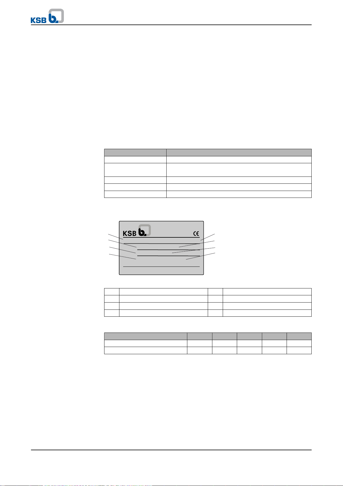
5.3 Name plate
Fig. 2: Hya-Solo DV name plate
1 Type series/size 2 Rated voltage
3 Frequency 4 Maximum head
5 Series number 6 Max. current consumption
7 Enclosure 8 Maximum flow rate
Key t o t he se r i e s num b e r
Calendar year 2009 2010 2011 2012 2013
1st half of the year S-U S-W S-Y S-A S-C
2nd half of the year S-V S-X S-Z S-B S-D
5.4 Design details
Desig n
The pressure booster system consists of a non-self-priming multistage high-pressure
centrifugal pump with suction and discharge side shut-off valves. The shut-off valves
enable dismantling of the pump or check valve without draining the piping system.
The check valve on the discharge side prevents backflow through the pump when the
pump is not running and reduces the load on the mechanical seal.
An accumulator, a pressure transmitter and a pressure gauge are fitted on the
discharge side of the pressure booster system.
The PumpDrive speed control system is mounted on and ready-wired to the pump
Hya®-Solo DV
13 of 56
1
5
2
3
6
4
5 Description
set.
The system comes with separate rubber anti-vibration pads.
Design
Function
Automatic mode
Function
Manual mode
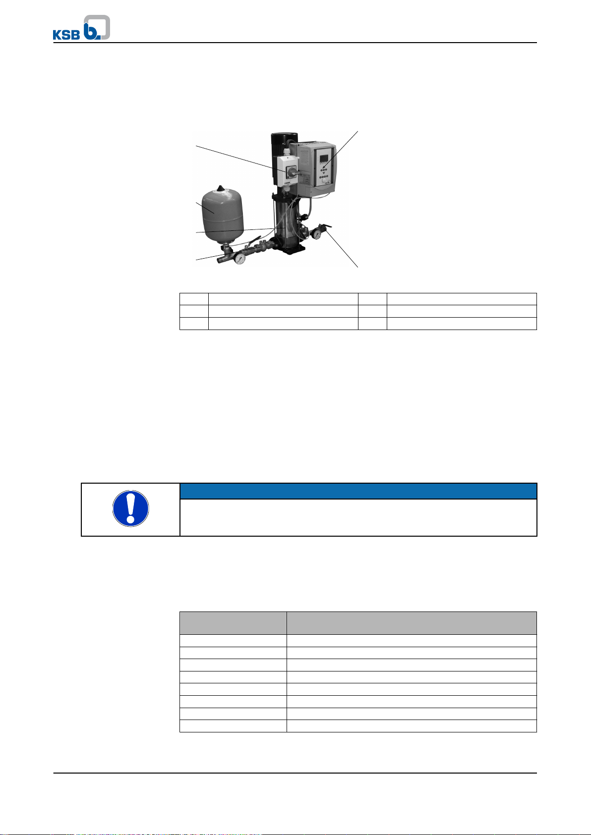
5.5 Configuration and function
Fig. 3: Hya-Solo DV
1 Master switch 2 Accumulator
3 Pump 4 Pressure transmitter
5 PumpDrive 6 Valves
The fully automatic pressure booster system is equipped with a non-self-priming
vertical high-pressure pump (1) for pumping the fluid handled to the consumer
installations at a constant pressure.
The pump is started as a function of pressure and stopped as a function of flow by a
fully automatic control unit. If the pressure drops below the pre-set pressure, the
pump starts up and the frequency inverter controls the unit to maintain the set
pressure, so that the pressure is kept constant.
As the consumption decreases, the speed is reduced. At zero flow, the pressure
booster system stops after a set after-run period (45 to 360 seconds).
A key for manual operation is provided on the control panel. In manual mode the
pump operates at the pre-set minimum speed, independently of the automatic
system (pressure transmitter) or an External ON/OFF signal.
Example
NOTE
Continuous manual mode is reserved exclusively for emergencies!
Continuous operation of the pressure booster system in manual mode may result in
waste of energy and water.
In manual mode, a minimum flow (see table below) is essential to prevent the fluid
handled and the pump from overheating when no water is consumed at the
consumer installations.
Minim u m flow f o r pump i n manu a l mode
Table 5: Minimum consumption per pump in manual mode
Pump Minimum consumption per pump in manual mode
[l/h]
Movitec 2 300
Movitec 4 600
Movitec 10 1200
Movitec 18 2400
Movitec 32 4000
Movitec 45 4600
Movitec 65 6100
Movitec 90 8000
An open 1/2-inch tap equals a water consumption of approx. 800 to 1,200 l/h.
14 of 56
Hya®-Solo DV
5 Description
Function
Dry running protection
Pressure booster system
PumpDrive
The dry running protection function is active in automatic mode and manual mode.
A digital input is provided for connecting dry running protection equipment. When
the input is open, the control unit detects dry running and stops the pressure booster
system after approx. 10 seconds (factory setting).
5.6 Noise characteristics
For the noise level of the individual pumps please refer to the pump's operating
instructions.
5.7 Scope of supply
Depending on the model, the following items are included in the scope of supply:
▪ One Movitec vertical high-pressure centrifugal pump
▪ One check valve and shut-off valves
▪ Membrane-type direct-flow accumulator on the discharge side
▪ Pressure transmitter for the discharge side
▪ Vibration damping
▪ Pressure indication via pressure gauge
▪ Shut-off valves
▪ Self-cooling motor-mounted frequency inverter
▪ Plain-text display (for voltage, current, power, speed, frequency)
▪ Control panel with operating keys (manual-0-automatic), navigation and
function keys
▪ LEDs signalling operational availability (green), warning (yellow), alert (red)
▪ Two freely parameterisable relay outputs (operation/fault, alert, etc.),
2x NO contacts 250 V AC/1 A
▪ Analog input for external setpoint adjustment
▪ Analog output for transmitting the actual value, motor speed, etc.
▪ Lockable master switch (repair switch)
5.8 Dimensions and weights
For dimensions and weights please refer to the outline drawings of the pressure
booster system.
5.9 Terminal wiring diagram
5.9.1 Power terminals
NOTE
The PumpDrive is wired to the master switch, the motor and the pressure sensor at the
factory. Work at the power terminals is only required if the PumpDrive needs to be
removed.
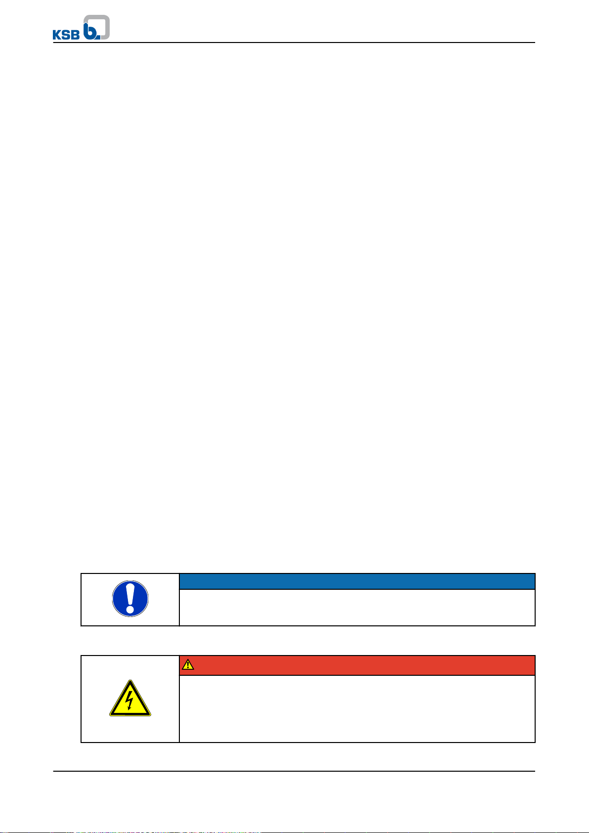
The power terminals are located underneath the V-shaped cover.
DANGER
Electrical connection work by unqualified personnel
Danger of death from electric shock!
▷ Always have the electrical connections installed by a trained electrician.
▷ Observe regulations IEC 30364 (DIN VDE 0100) and, for explosion-proof models,
IEC 60079 (DIN VDE 0164).
Hya®-Solo DV
15 of 56
5 Description
Removing the L-shaped
cover.
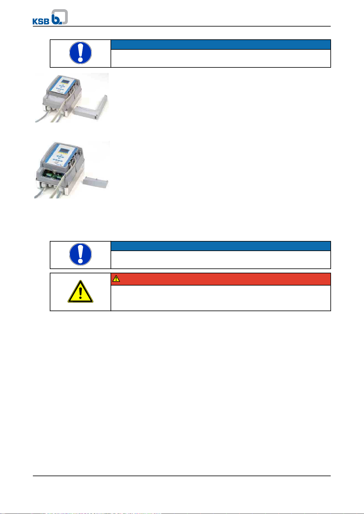
Removing the V-shaped
cover.
Route the power/motor cable through the cable glands (as shown in table 20, section
NOTE
The housing cover must not be opened.
Non-compliance will result in forfeiture of any and all warranty claims.
Remove the cross-head screws on the L-shaped cable cover for the control cables and
remove the cover.
Remove the cross-head screws on the V-shaped cover for the mains and motor connection
and remove the cover.
6.4.6) and connect them to the appropriate terminals (see Fig. 10 and Fig. 11).
When closing the covers, make sure that the sealing elements are properly seated.
NOTE
The screws fastening the cover of the mains and motor terminal box must be tightened to
a torque of 1.2 Nm to ensure that the device has IP55 enclosure protection.
DANGER
Open terminals and connectors of brake resistor.
Danger to life!
▷ Do not open the terminals and connectors of the brake resistor.
16 of 56
Hya®-Solo DV
+24VIN 0
PTC
PE L1 L2 L3
PE
L1
L2
L3
N
1 2 3 4 5 6
U V W
B
A
M
3~
+24VIN 0
PTC
PE L1 L2 L3
PE
L1
L2
L3
N
1 2 3 4 5 6
U V W
B
A
M
3~
5 Description
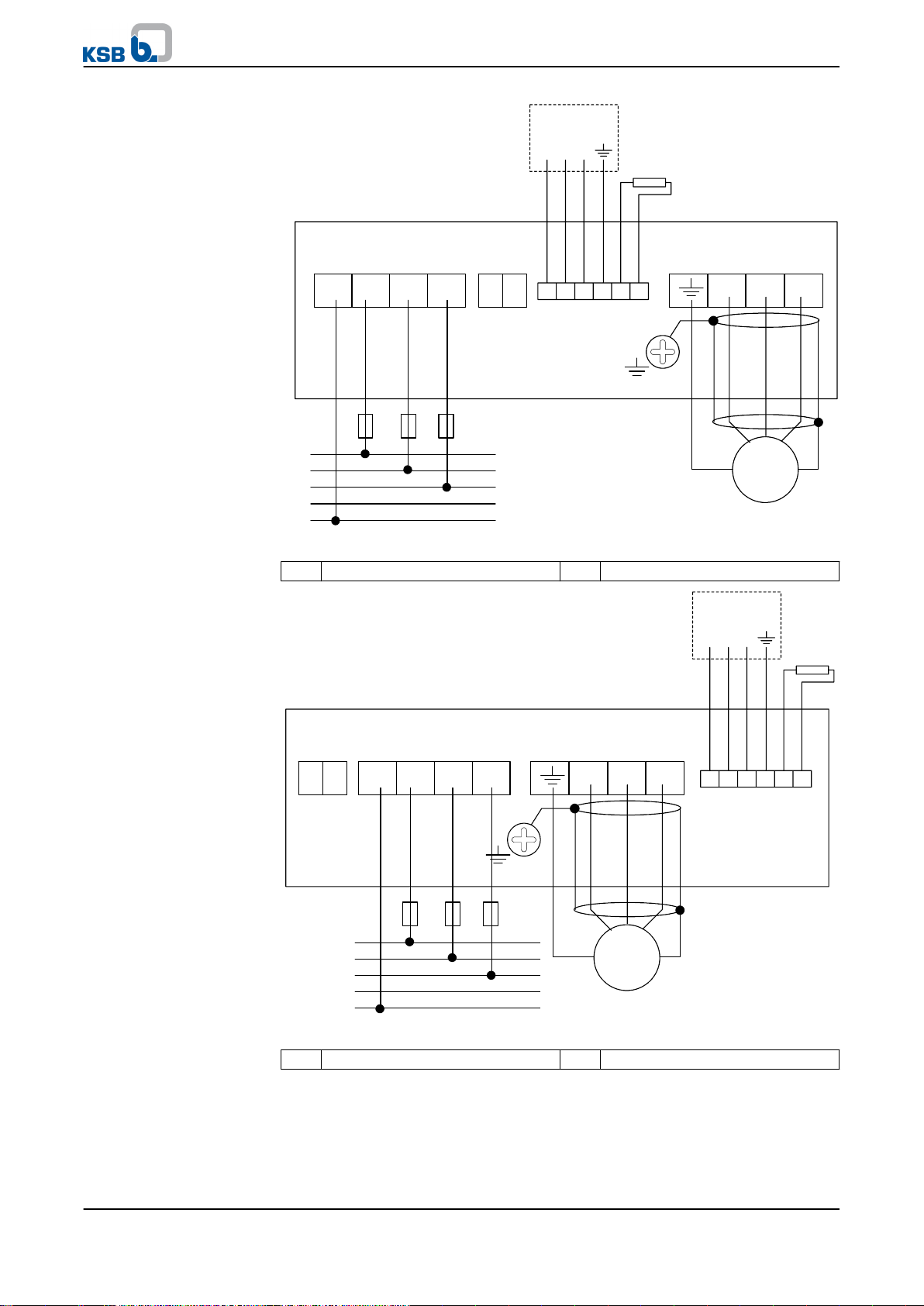
Fig. 4: Power supply and motor wiring up to 7.5 kW
A Analog input 2 B Brake resistor
Fig. 5: Power supply and motor wiring from 11 kW
A Analog input 2 B Brake resistor
Hya®-Solo DV
17 of 56
 Loading...