

Page 1
Pressure Booster System
Hya®-Solo DV
from series S-V/1
Installation/Operating
Manual
Page 2

Your contact:
Tel: 01474 832498
Email: technique1988@gmail.com
Web: www.techniquetergravesend.co.uk
Legal information/Copyright
Installation/Operating Manual Hya®-Solo DV
Original operating manual
KSB Aktiengesellschaft Frankenthal
All rights reserved. Contents provided herein must neither be distributed, copied, reproduced, edited
or processed for any other purpose, nor otherwise transmitted, published or made available to a third
party without KSB´s express written consent.
Subject to technical modification without prior notice.
© KSB Aktiengesellschaft Frankenthal 22.4.2010
Page 3

Contents
Contents
Glossary ................................................................................................ 5
1 General ................................................................................................ 6
1.1 Principles .......................................................................................................... 6
1.2 Installation of partly completed machinery .................................................. 6
1.3 Target group ................................................................................................... 6
1.4 Other applicable documents .......................................................................... 6
1.5 Symbols ............................................................................................................ 6
2 Safety ................................................................................................... 7
2.1 Key to safety symbols/markings ..................................................................... 7
3 Software Changes ............................................................................. 10
4 Transport/Temporary Storage/Disposal ........................................... 11
4.1 As-delivered condition .................................................................................. 11
4.2 Transport ....................................................................................................... 11
4.3 Storage/Preservation ..................................................................................... 11
4.4 Return to supplier ........................................................................................ 12
4.5 Disposal of pressure booster system ............................................................ 12
5 Description ........................................................................................ 13
5.1 General description ....................................................................................... 13
5.2 Designation ................................................................................................... 13
5.3 Name plate .................................................................................................... 13
5.4 Design details ................................................................................................ 13
5.5 Configuration and function ......................................................................... 14
5.6 Noise characteristics ...................................................................................... 15
5.7 Scope of supply ............................................................................................. 15
5.8 Dimensions and weights ............................................................................... 15
5.9 Terminal wiring diagram .............................................................................. 15
6 Installation at Site ............................................................................. 21
6.1 Installation to DIN 1988 ................................................................................ 21
6.2 Checks to be carried out prior to installation ............................................. 21
6.3 Installing the pressure booster system ......................................................... 21
6.4 Installing the piping ...................................................................................... 22
6.5 Installing unpressurised inlet tanks .............................................................. 23
6.6 Fitting the dry running protection device ................................................... 23
6.7 Connection to power supply ........................................................................ 24
7 Commissioning/Start-up/Shutdown ................................................. 26
7.1 Commissioning/start-up ................................................................................ 26
7.2 Switching on the pressure booster system .................................................. 27
Hya®-Solo DV
3 of 56
Page 4

Contents
7.3 Check list for commissioning/start-up .......................................................... 27
7.4 Shutdown ...................................................................................................... 28
8 Operating the Pressure Booster System ........................................... 29
8.1 Control panel functions ................................................................................ 29
8.2 Menu structure .............................................................................................. 32
8.3 Access levels ................................................................................................... 33
8.4 Displaying and changing parameters .......................................................... 34
8.5 Monitoring .................................................................................................... 35
8.6 Description of parameters ............................................................................ 35
8.7 Adjusting the settings ................................................................................... 36
9 Servicing/Maintenance ...................................................................... 43
9.1 General notes/Safety regulations ................................................................. 43
9.2 Servicing/inspection ...................................................................................... 44
10 Trouble-shooting ............................................................................... 46
10.1 Hya-Solo DV ................................................................................................... 46
10.2 PumpDrive ..................................................................................................... 47
11 Related Documents ........................................................................... 49
11.1 List of components ........................................................................................ 49
12 EC Declaration of Conformity .......................................................... 51
13 Certificate of Decontamination ....................................................... 53
14 Commissioning Report ...................................................................... 54
Index .................................................................................................. 55
4 of 56
Hya®-Solo DV
Page 5

Glossary
Glossary
Accumulator
The accumulator serves to compensate for
pressure losses in the piping system
downstream of the pressure booster system
which may be caused by the consumption of
small quantities of water. As a result, the
frequency of starts of the pressure booster
system is minimised.
Automatic mode
The pump is started as a function of pressure
and stopped as a function of flow.
Certificate of decontamination
A certificate of decontamination certifies that
the pressure booster system has been properly
cleaned and decontaminated to eliminate any
environmental and health hazards arising from
components in contact with the fluid handled.
Dry running protection
Dry running protection devices prevent the
pump from being operated without the fluid to
be handled, which would result in pump
damage.
Manual mode
In manual mode, the system is operated at a
selectable speed via the frequency inverter,
independently of the control unit.
Noise characteristics
The noise emission to be expected, indicated as
sound pressure level LpA in dB(A)
PumpDrive
KSB frequency inverter mounted on the pump
set.
Hya®-Solo DV
5 of 56
Page 6
1 General
1 General
1.1 Principles
This manual is supplied as an integral part of the type series and variants indicated
on the front cover. It describes the proper and safe use of this equipment in all
phases of operation.
The name plate indicates the type series/size, the main operating data and the order
number. The series/serial number clearly identifies the pressure booster system and
serves as identification for all further business processes.
In the event of damage, immediately contact your nearest KSB service centre to
maintain the right to claim under warranty.
Noise characteristics (⇨ Section 5.6 Page 15)
1.2 Installation of partly completed machinery
To install partly completed machinery supplied by KSB, please refer to the subsections under Servicing/Maintenance.
1.3 Target group
This manual is aimed at the target group of trained and qualified specialist technical
personnel. (⇨ Section 2.1.3 Page 8)
1.4 Other applicable documents
Table 1: Overview of other applicable documents
Document Contents
Sub-supplier documentation Operating manuals, logic diagram and other
product literature of accessories and integrated
machinery components
1.5 Symbols
Table 2: Symbols used in this manual
Symbol Description
✓ Conditions which need to be fulfilled before proceeding with the
step-by-step instructions
⊳ Safety instructions
⇨ Result of an action
⇨ Cross-references
1.
2.
Step-by-step instructions
Note
Recommendations and important information on how to handle
the product
6 of 56
Hya®-Solo DV
Page 7
!
DANGER
!
WARNING
CAUTION
!
DANGER
2 Safety
2 Safety
All the information contained in this section refers to hazardous situations.
2.1 Key to safety symbols/markings
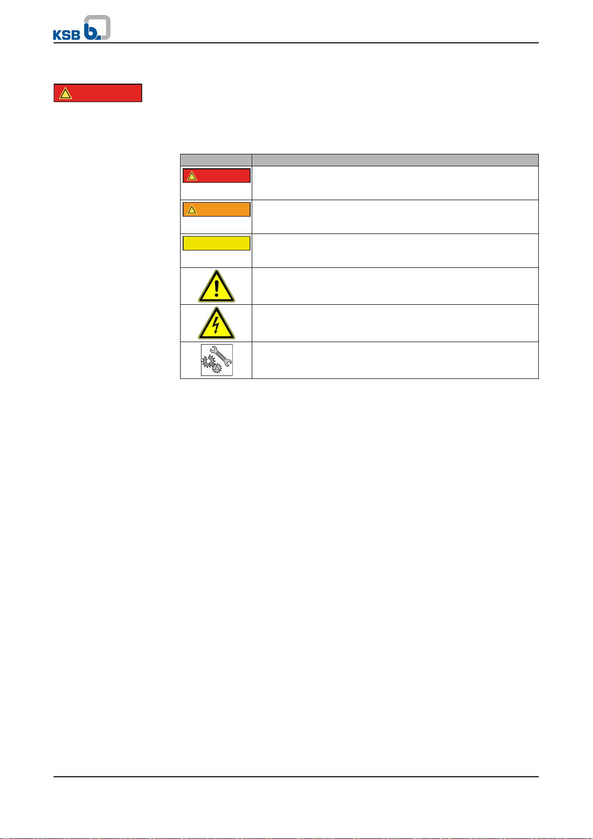
Table 3: Definition of safety symbols/markings
Symbol Description
DANGER
indicates a high-risk hazard which, if not avoided, will result in
death or serious injury.
WARNING
indicates a medium-risk hazard which, if not avoided, could result
in death or serious injury.
CAUTION
indicates a hazard which, if not avoided, could result in damage to
the machine and its functions.
General hazard
in conjunction with one of the signal words indicates a hazard
which will or could result in death or serious injury.
Electrical hazard
identifies information about protection against electrical voltage.
In conjunction with the signal word CAUTION, this symbol indicates
a hazard for the machine and its functions.
2.1.1 General
This manual contains general installation, operating and maintenance instructions
that must be observed to ensure safe operation of the pressure booster system and
prevent personal injury and damage to property.
The safety information in all sections of this manual must be complied with.
This manual must be read and completely understood by the responsible specialist
personnel/operators prior to installation and commissioning.
The contents of this manual must be available to the specialist personnel at the site
at all times.
Information attached directly to the pressure booster system must always be
complied with and be kept in a perfectly legible condition at all times. This applies
to, for example:
▪ Arrow indicating the direction of rotation
▪ Markings for connections
▪ Name plate
The operator is responsible for ensuring compliance with all local regulations which
are not taken into account in this manual.
2.1.2 Intended use
The pressure booster system must only be operated within the operating limits which
are described in the other applicable documents.
▪ Only operate pressure booster systems which are in perfect technical condition.
▪ Do not operate partially assembled pressure booster systems.
▪ The pressure booster system must only handle the fluids described in the product
literature of the respective design variant.
▪ Never operate the pressure booster system without the fluid to be handled.
Hya®-Solo DV
7 of 56
Page 8

2 Safety
▪ Observe the minimum flow rates indicated in the product literature (to prevent
overheating, bearing damage, etc.).
▪ Observe the maximum flow rates indicated in the product literature (to prevent
overheating, mechanical seal damage, cavitation damage, bearing damage, etc.).
▪ Do not throttle the flow rate on the suction side of the pressure booster system
(to prevent cavitation damage).
▪ Consult the manufacturer about any use or mode of operation not described in
the product literature.
Preve n t i on of f o resee a b l e mis u s e
▪ Never exceed the permissible operating limits specified in the product literature
regarding pressure, temperature, etc..
▪ Observe all safety information and instructions in this manual.
2.1.3 Personnel qualification and training
All personnel involved must be fully qualified to install, operate, maintain and
inspect the machinery this manual refers to.
The responsibilities, competence and supervision of all personnel involved in
installation, operation, maintenance and inspection must be clearly defined by the
operator.
Deficits in knowledge must be rectified by sufficiently trained specialist personnel
training and instructing the personnel who will carry out the respective tasks. If
required, the operator can commission the manufacturer/supplier to train the
personnel.
Training on the pressure booster system must always be supervised by technical
specialist personnel.
2.1.4 Consequences and risks caused by non-compliance with these operating
instructions
▪ Non-compliance with these operating instructions will lead to forfeiture of any
and all rights to claims for damages.
▪ Non-compliance can, for example, have the following consequences:
–
Hazards to persons due to electrical, thermal, mechanical and chemical
effects and explosions
– Failure of important product functions
– Failure of prescribed maintenance and servicing practices
– Hazard to the environment due to leakage of hazardous substances
8 of 56
2.1.5 Safety awareness
In addition to the safety instructions contained in this manual and the intended use,
the following safety instructions shall be complied with:
▪ Accident prevention, health and safety regulations
▪ Explosion protection regulations
▪ Safety regulations for handling hazardous substances
▪ Applicable standards and laws
2.1.6 Safety information for the operator/user
▪ The operator shall fit contact guards for hot, cold and moving parts and check
that the guards function properly.
▪ Never remove a contact guard while the pump is running.
▪ Eliminate all electrical hazards.
Hya®-Solo DV
Page 9

2 Safety
2.1.7 Safety information for maintenance, inspection and installation work
▪ Modifications or alterations of the pressure booster system are only permitted
with the manufacturer's prior consent.
▪ Use only original spare parts or parts authorised by the manufacturer. The use of
other parts can invalidate any liability of the manufacturer for resulting damage.
▪ The operator ensures that all maintenance, inspection and installation work is
performed by authorised, qualified specialist personnel who are thoroughly
familiar with the manual.
▪ Carry out work on the pressure booster system during standstill only.
▪ The pump casing must have cooled down to ambient temperature.
▪ Pump pressure must have been released and the pump must have been drained.
▪ When taking the pressure booster system out of service always adhere to the
procedure described in the manual.
▪ Decontaminate pressure booster systems which handle fluids posing a health
hazard.
▪ As soon as the work is completed, re-install and/or re-activate any safety-relevant
and protective devices. Before returning the product to service, observe all
instructions on commissioning. (⇨ Section 7.1 Page 26)
▪ Make sure the pressure booster system cannot be accessed by unauthorised
persons (e.g. children).
2.1.8 Unauthorised modes of operation
Always observe the limits stated in the product literature.
The warranty relating to the operating reliability and safety of the pressure booster
system supplied is only valid if the equipment is used in accordance with its intended
use. (⇨ Section 2.1.2 Page 7)
Hya®-Solo DV
9 of 56
Page 10

3 Software Changes
3 Software Changes
The software has been specially created for this product and thoroughly tested.
It is impermissible to make any changes or additions to the software or parts of the
software. Software updates supplied by KSB are excluded from this rule.
10 of 56
Hya®-Solo DV
Page 11

4 Transport/Temporary Storage/Disposal
4 Transport/Temporary Storage/Disposal
4.1 As-delivered condition
NOTE
Prior to dispatch, the pressure booster system was tested and inspected to ensure full
compliance with the specifications and should therefore be in perfect electrical and
mechanical condition upon arrival at its destination.
It is recommended that the pressure booster system be inspected for in-transit damage
immediately upon receipt. If there are any complaints or objections, the recipient and
carrier must jointly draw up a damage report.
4.2 Transport
NOTE
The pressure booster system is bolted to a pallet and wrapped in plastic foil for shipping
and temporary storage. All connecting points are capped.
DANGER
Pressure booster system tipping over
Risk of injury by falling pressure booster system!
▷ Never suspend the pressure booster system by its power cable.
▷ Observe the local accident prevention regulations.
▷ Use suitable, approved transport equipment, e.g. crane, forklift or pallet trucks.
▷ Attach the pressure booster system to crane lifting tackle as shown, or use a
forklift or pallet truck to move the pallet.
Fig. 1: Transporting the pressure booster system
✓ The pressure booster system has been checked for in-transit damage.
Make sure the transport equipment is suitable for safely carrying the indicated
1.
load.
2. Transport the pressure booster system to the place of installation.
3. Attach the pressure booster system to the lifting tackle as shown, lift it off the
pallet and dispose of the pallet.
4. Use suitable lifting equipment to lift the pressure booster system and carefully
put it down at the place of installation.
4.3 Storage/Preservation
If commissioning is to take place some time after delivery, we recommend that the
following measures be taken when storing the pressure booster system:
Hya®-Solo DV
11 of 56
Page 12

4 Transport/Temporary Storage/Disposal
CAUTION
Damage during storage by frost, moisture, dirt, UV radiation or vermin
Corrosion/contamination of pressure boosting system!
▷ Store the pressure booster system in a frost-proof room. Do not store the unit
outdoors.
CAUTION
Wet, contaminated or damaged openings and connections
Leakage or damage of the pressure booster system!
▷ Only open the openings of the pressure booster system at the time of
installation.
Store the pressure booster system in a dry, protected room where the atmospheric
humidity is as constant as possible.
4.4 Return to supplier
1. Drain the pressure booster system as per operating instructions.
Always flush and clean the pressure booster system, particularly if it has been
2.
used for handling noxious, explosive, hot or other hazardous fluids.
3. If the fluids handled by the system leave residues which might lead to corrosion
when coming into contact with atmospheric humidity, or which might ignite
when coming into contact with oxygen, the pressure booster system must also be
neutralised and blown through with anhydrous inert gas for drying purposes.
4. Always complete and enclose a certificate of decontamination when returning
the pressure booster system.
It is imperative to indicate any safety and decontamination measures taken.
NOTE
If required, a blank certificate of decontamination can be downloaded from the KSB web
site at: www.ksb.com/certificate_of_decontamination
4.5 Disposal of pressure booster system
WARNING
Fluids posing a health hazard
Hazardous to persons and the environment!
▷ Collect and properly dispose of flushing liquid and any fluid residues.
▷ Wear safety clothing and a protective mask, if required.
▷ Observe all legal regulations on the disposal of fluids posing a health hazard.
1. Dismantle the pressure booster system.
Collect greases and other lubricants during dismantling.
2. Separate and sort the pump materials, e.g. by:
- Metals
- Plastics
- Electronic waste
- Greases and other lubricants
3. Dispose of materials in accordance with local regulations or in another controlled
manner.
12 of 56
Hya®-Solo DV
Page 13
Hya-Solo DV 1808 S-U
ZNI1448 P
29 132 276 Made by KSB
400 V 3~ 15,50 A
H
max
: 115 m Q
max
: 23 m3/h
50 Hz IP 55
Aktiengesellschaft
D-67225 Frankenthal
1
2
4
3
6
5
8
7
5 Description
5 Description
5.1 General description
The fully automatic pressure booster package system
▪ with one vertical high-pressure pump
▪ with a motor-mounted PumpDrive frequency inverter ensuring a constant supply
pressure at the consumer installations
complies with DIN 1988 in configuration and function.
5.2 Designation
Examp l e : Hya- S o l o DV / 0 4 05 / 2 - 4
Table 4: Key to the designation
Code Description
Hya-Solo Pressure booster system with one pump
DV Model with three-phase motor, speed-controlled, pressure-
dependent starting and flow-dependent stopping
04 Pump size
05 Number of pump stages
2 - 4 Inlet pressure in bar
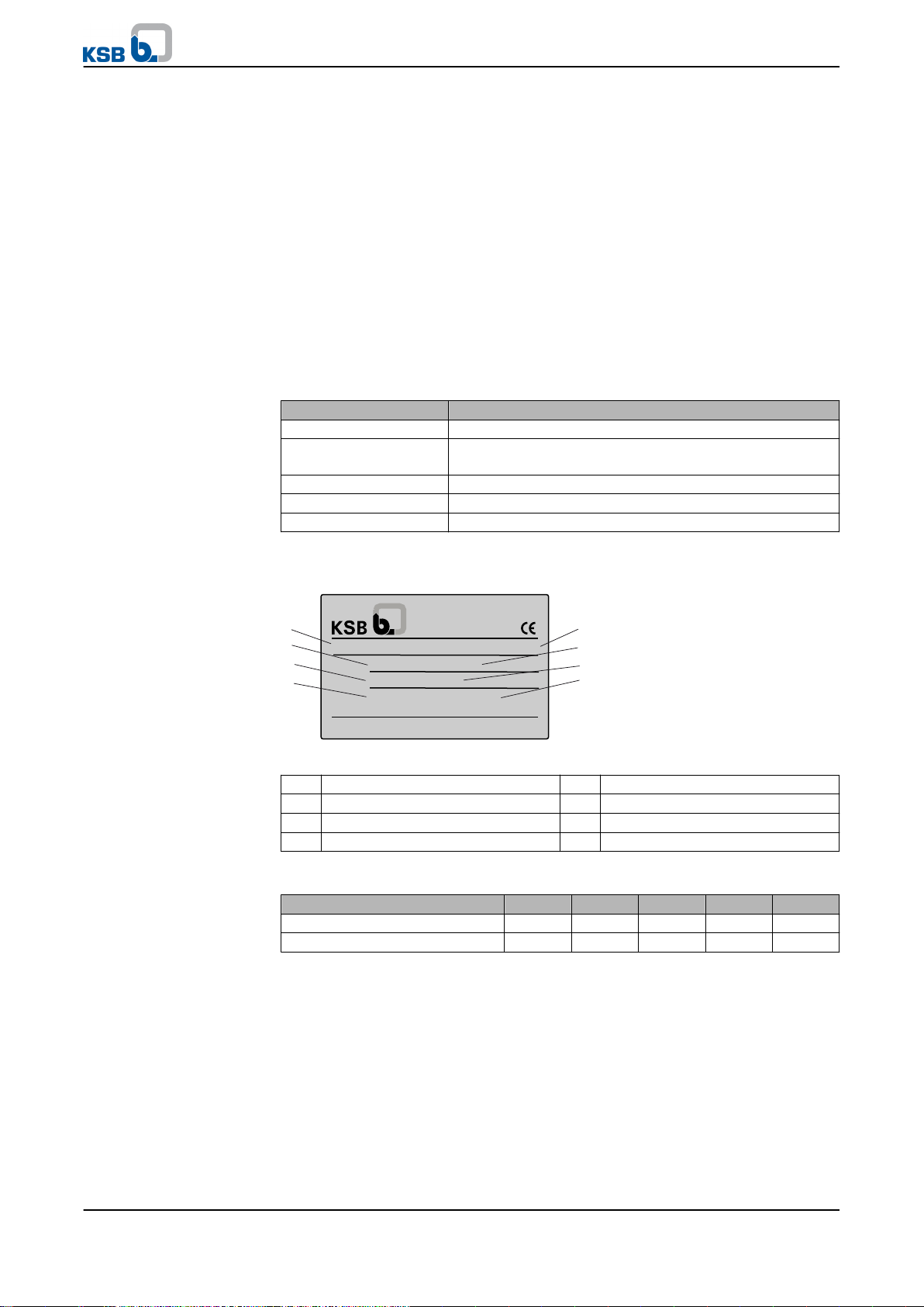
5.3 Name plate
Fig. 2: Hya-Solo DV name plate
1 Type series/size 2 Rated voltage
3 Frequency 4 Maximum head
5 Series number 6 Max. current consumption
7 Enclosure 8 Maximum flow rate
Key t o t he se r i e s num b e r
Calendar year 2009 2010 2011 2012 2013
1st half of the year S-U S-W S-Y S-A S-C
2nd half of the year S-V S-X S-Z S-B S-D
5.4 Design details
Desig n
The pressure booster system consists of a non-self-priming multistage high-pressure
centrifugal pump with suction and discharge side shut-off valves. The shut-off valves
enable dismantling of the pump or check valve without draining the piping system.
The check valve on the discharge side prevents backflow through the pump when the
pump is not running and reduces the load on the mechanical seal.
An accumulator, a pressure transmitter and a pressure gauge are fitted on the
discharge side of the pressure booster system.
The PumpDrive speed control system is mounted on and ready-wired to the pump
Hya®-Solo DV
13 of 56
Page 14
1
5
2
3
6
4
5 Description
set.
The system comes with separate rubber anti-vibration pads.
Design
Function
Automatic mode
Function
Manual mode
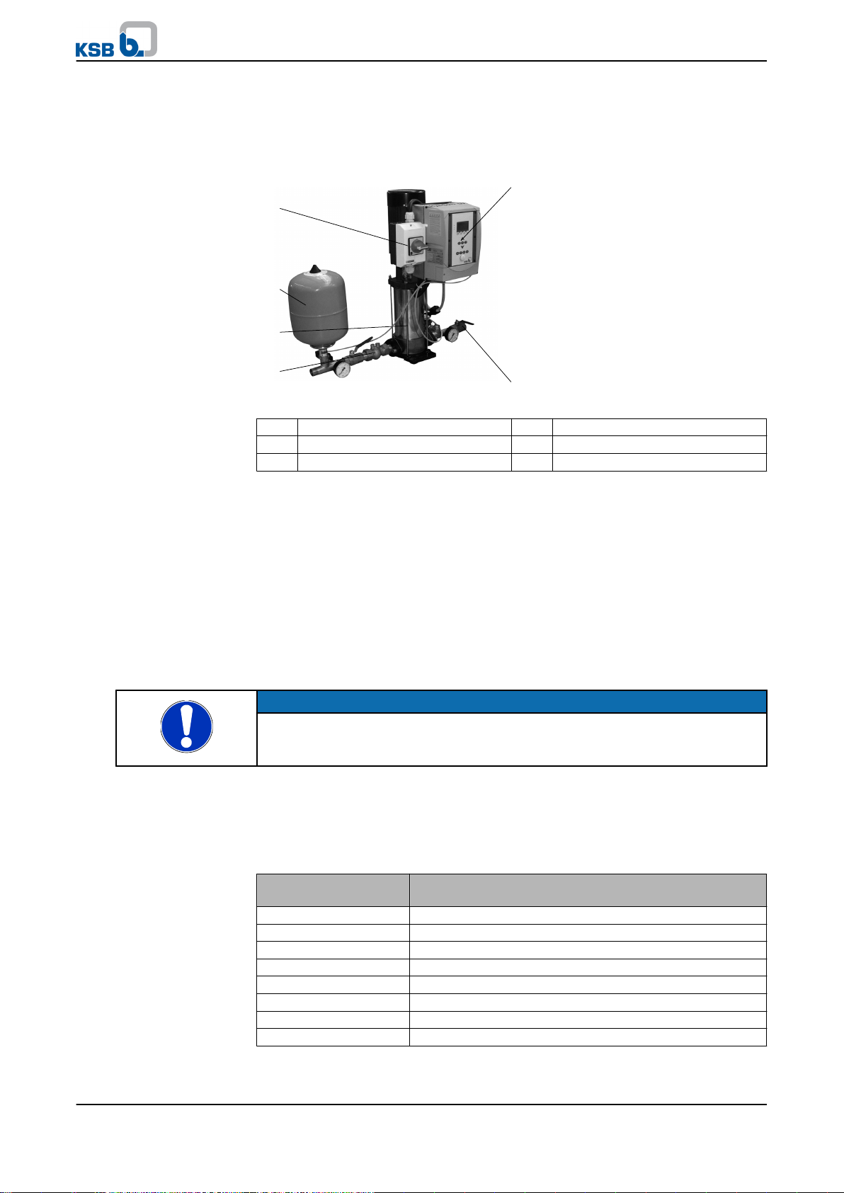
5.5 Configuration and function
Fig. 3: Hya-Solo DV
1 Master switch 2 Accumulator
3 Pump 4 Pressure transmitter
5 PumpDrive 6 Valves
The fully automatic pressure booster system is equipped with a non-self-priming
vertical high-pressure pump (1) for pumping the fluid handled to the consumer
installations at a constant pressure.
The pump is started as a function of pressure and stopped as a function of flow by a
fully automatic control unit. If the pressure drops below the pre-set pressure, the
pump starts up and the frequency inverter controls the unit to maintain the set
pressure, so that the pressure is kept constant.
As the consumption decreases, the speed is reduced. At zero flow, the pressure
booster system stops after a set after-run period (45 to 360 seconds).
A key for manual operation is provided on the control panel. In manual mode the
pump operates at the pre-set minimum speed, independently of the automatic
system (pressure transmitter) or an External ON/OFF signal.
Example
NOTE
Continuous manual mode is reserved exclusively for emergencies!
Continuous operation of the pressure booster system in manual mode may result in
waste of energy and water.
In manual mode, a minimum flow (see table below) is essential to prevent the fluid
handled and the pump from overheating when no water is consumed at the
consumer installations.
Minim u m flow f o r pump i n manu a l mode
Table 5: Minimum consumption per pump in manual mode
Pump Minimum consumption per pump in manual mode
[l/h]
Movitec 2 300
Movitec 4 600
Movitec 10 1200
Movitec 18 2400
Movitec 32 4000
Movitec 45 4600
Movitec 65 6100
Movitec 90 8000
An open 1/2-inch tap equals a water consumption of approx. 800 to 1,200 l/h.
14 of 56
Hya®-Solo DV
Page 15
5 Description
Function
Dry running protection
Pressure booster system
PumpDrive
The dry running protection function is active in automatic mode and manual mode.
A digital input is provided for connecting dry running protection equipment. When
the input is open, the control unit detects dry running and stops the pressure booster
system after approx. 10 seconds (factory setting).
5.6 Noise characteristics
For the noise level of the individual pumps please refer to the pump's operating
instructions.
5.7 Scope of supply
Depending on the model, the following items are included in the scope of supply:
▪ One Movitec vertical high-pressure centrifugal pump
▪ One check valve and shut-off valves
▪ Membrane-type direct-flow accumulator on the discharge side
▪ Pressure transmitter for the discharge side
▪ Vibration damping
▪ Pressure indication via pressure gauge
▪ Shut-off valves
▪ Self-cooling motor-mounted frequency inverter
▪ Plain-text display (for voltage, current, power, speed, frequency)
▪ Control panel with operating keys (manual-0-automatic), navigation and
function keys
▪ LEDs signalling operational availability (green), warning (yellow), alert (red)
▪ Two freely parameterisable relay outputs (operation/fault, alert, etc.),
2x NO contacts 250 V AC/1 A
▪ Analog input for external setpoint adjustment
▪ Analog output for transmitting the actual value, motor speed, etc.
▪ Lockable master switch (repair switch)
5.8 Dimensions and weights
For dimensions and weights please refer to the outline drawings of the pressure
booster system.
5.9 Terminal wiring diagram
5.9.1 Power terminals
NOTE
The PumpDrive is wired to the master switch, the motor and the pressure sensor at the
factory. Work at the power terminals is only required if the PumpDrive needs to be
removed.
The power terminals are located underneath the V-shaped cover.
DANGER
Electrical connection work by unqualified personnel
Danger of death from electric shock!
▷ Always have the electrical connections installed by a trained electrician.
▷ Observe regulations IEC 30364 (DIN VDE 0100) and, for explosion-proof models,
IEC 60079 (DIN VDE 0164).
Hya®-Solo DV
15 of 56
Page 16
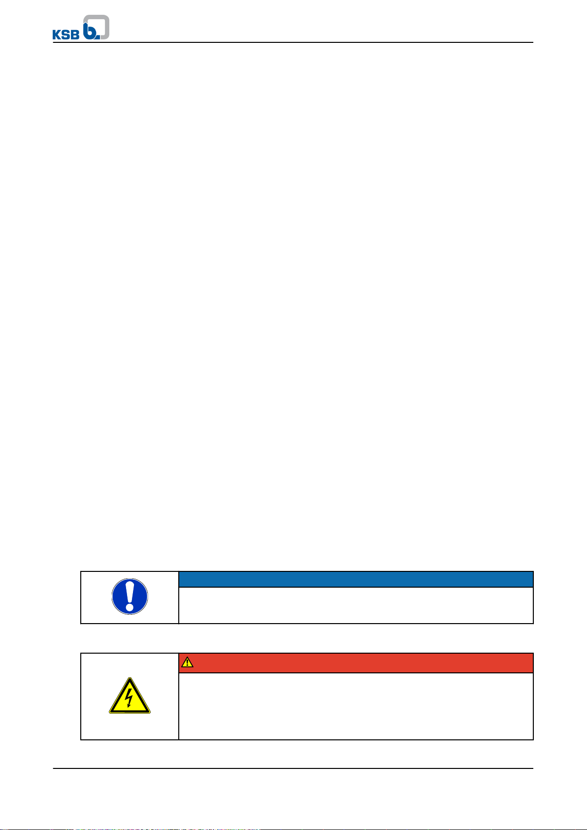
5 Description
Removing the L-shaped
cover.
Removing the V-shaped
cover.
Route the power/motor cable through the cable glands (as shown in table 20, section
NOTE
The housing cover must not be opened.
Non-compliance will result in forfeiture of any and all warranty claims.
Remove the cross-head screws on the L-shaped cable cover for the control cables and
remove the cover.
Remove the cross-head screws on the V-shaped cover for the mains and motor connection
and remove the cover.
6.4.6) and connect them to the appropriate terminals (see Fig. 10 and Fig. 11).
When closing the covers, make sure that the sealing elements are properly seated.
NOTE
The screws fastening the cover of the mains and motor terminal box must be tightened to
a torque of 1.2 Nm to ensure that the device has IP55 enclosure protection.
DANGER
Open terminals and connectors of brake resistor.
Danger to life!
▷ Do not open the terminals and connectors of the brake resistor.
16 of 56
Hya®-Solo DV
Page 17
+24VIN 0
PTC
PE L1 L2 L3
PE
L1
L2
L3
N
1 2 3 4 5 6
U V W
B
A
M
3~
+24VIN 0
PTC
PE L1 L2 L3
PE
L1
L2
L3
N
1 2 3 4 5 6
U V W
B
A
M
3~
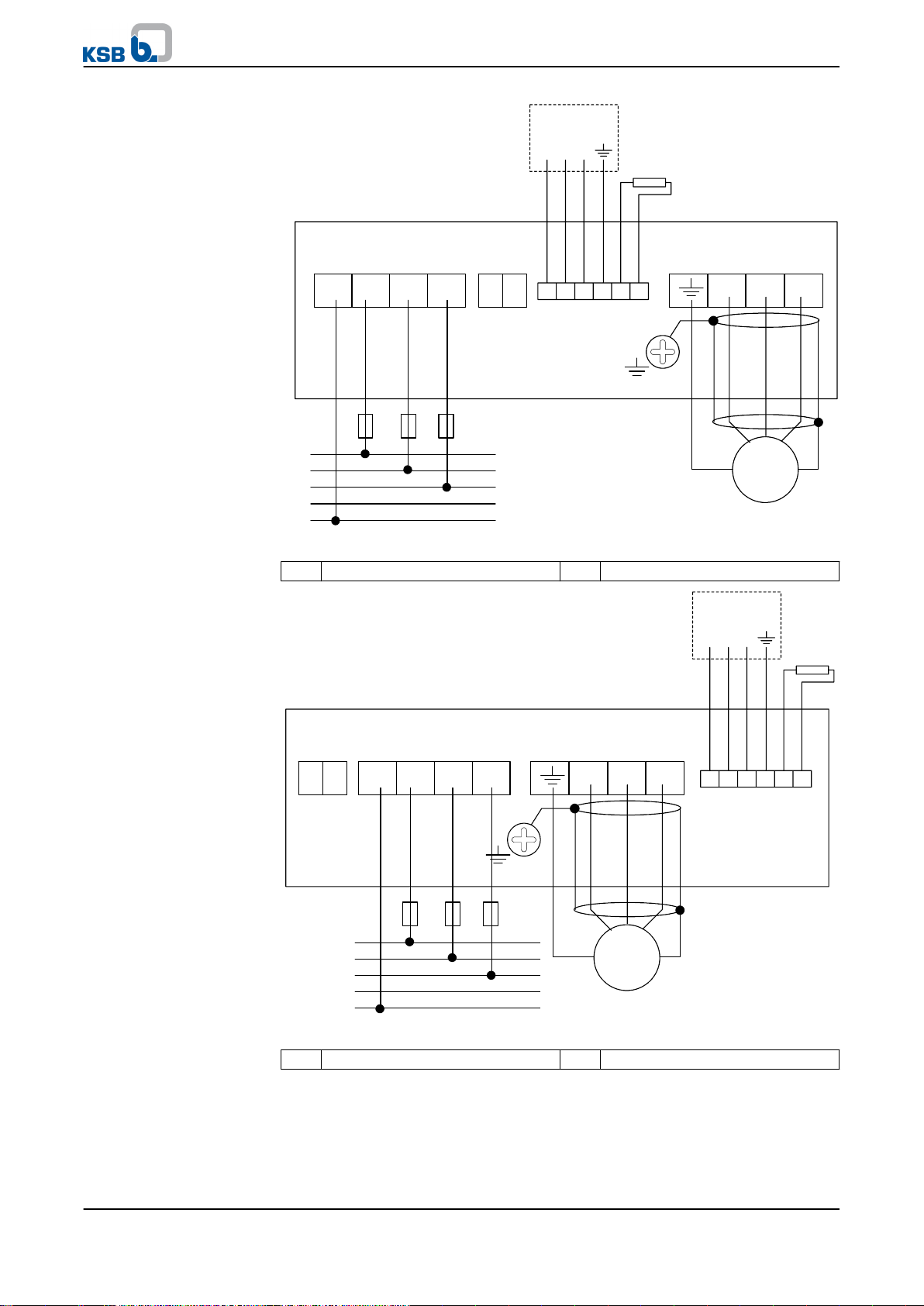
5 Description
Fig. 4: Power supply and motor wiring up to 7.5 kW
A Analog input 2 B Brake resistor
Fig. 5: Power supply and motor wiring from 11 kW
A Analog input 2 B Brake resistor
Hya®-Solo DV
17 of 56
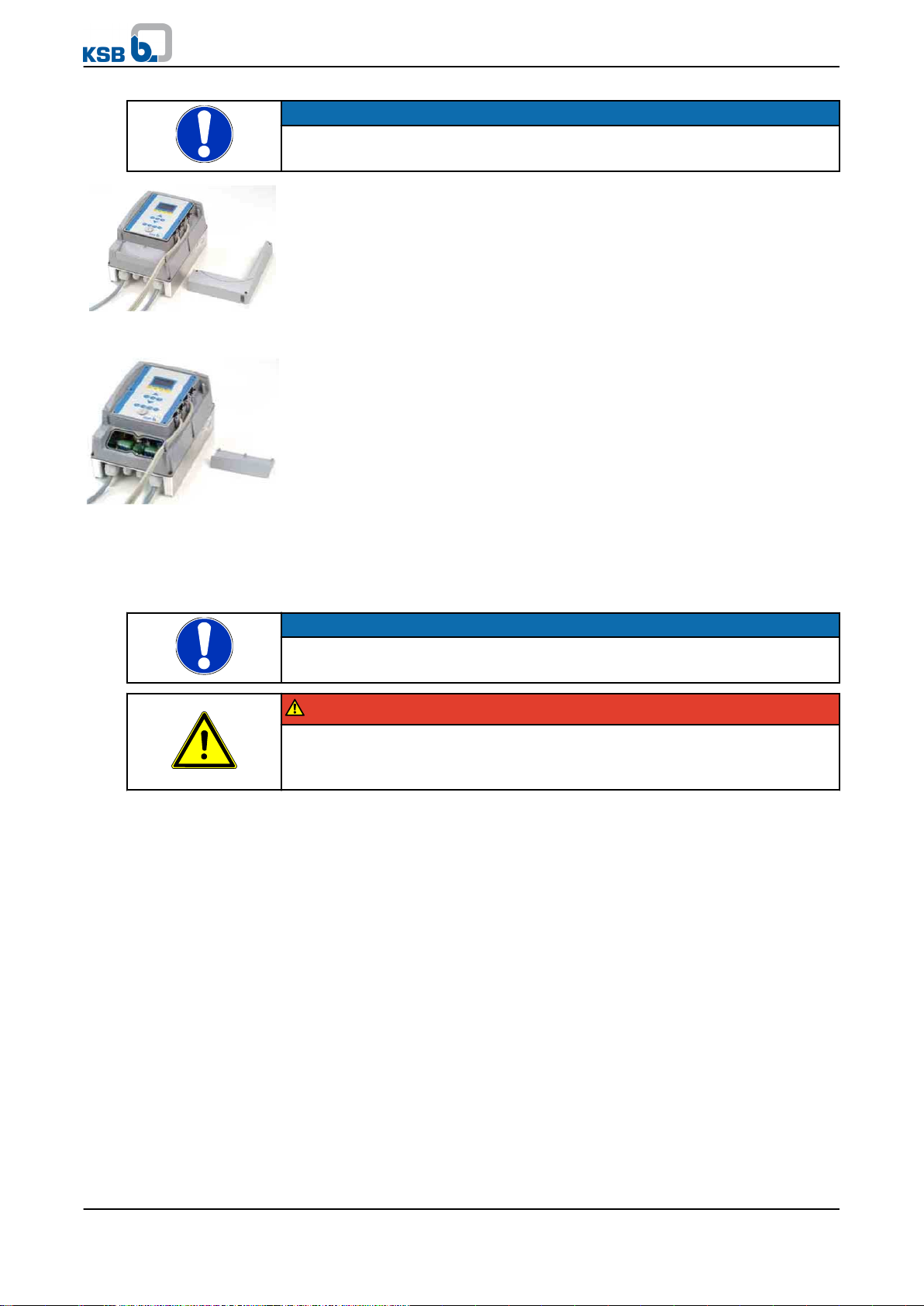
Page 18

5 Description
Fig. 6: Removing the
cover for the control cable
5.9.2 Connecting the control terminals
DANGER
Failure to interrupt power supply
Danger to life!
▷ Pull the mains plug or disconnect all electrical connections and secure against
accidental start-up.
NOTE
The housing cover must not be opened.
Non-compliance will result in forfeiture of any and all warranty claims.
The control terminals are located underneath the control panel.
This must be removed as follows.
1. Remove the cross-head screws on the L-shaped cover for the control cable and
remove the cover.
2. Remove the cross-head screws on the control panel and remove the control
panel.
NOTE
The screws fastening the cover of the mains and motor terminal box must be tightened to
a torque of 1.2 Nm to ensure that the device has IP55 enclosure protection.
The control terminal assignment is shown below.
The maximum cable cross-sections (wire size) which can be connected to the control
terminals of terminal strip P4 and terminal strip P7 are:
Table 6: Max. cable cross-sections to be connected to control terminals
Control
Rigid and flexible cables Flexible cable with wire end sleeve
terminals
Terminal stripP40.2 - 1.5 mm
Terminal stripP70.2 - 2.5 mm
2
2
0.75 mm
0.25 - 1.5 mm
2
2
18 of 56
Hya®-Solo DV
Page 19

1
10
2
3
4
5
6
7
8
9
10
2
3
4
6
7
8
9
20
19
18
17
16
15
14
13
12
11
1
5
4070:0011
P7
P4
GND P4
D16
D15
D14
D13
D12
D11
+24V
AGND
AN-OUT
SB1-GND
SB1+
SB1-
SB1-GND
SB1+
SB1SB1ZSB1Z+
AGND P7
AIN1
GND
AIN2
+24V
NO2
COM2
NO1
COM1
5 Description
Fig. 7: Inputs/output control terminals
Table 7: Terminal strip P4
Terminal Signal Description
20 0V Ground for +24 V
19 DIG IN6 Digital input (15/28 V DC)
18 DIG-IN5 Digital input (15/28 V DC)
17 DIG-IN4 Digital input (15/28 V DC)
16 DIG-IN3 Digital input (15/28 V DC)
15 DIG-IN2 Digital input (15/28 V DC)
14 DIG-IN1 Digital input (15/28 V DC)
13 +24 V +24 V DC voltage source
12 0V-AN Ground for AN-OUT
11 AN OUT Analog output 0-10 V.
10 SB1-GND Ground for CAN
9 SB1 + CAN signal
8 SB1 - CAN signal
7 PE (GROUND) Ground
6 PE (GROUND) Ground
5 SB1-GND Ground for CAN
4 SB1 + CAN signal
3 SB1 - CAN signal
2 SB1Z- Bus terminator for CAN
1 SB1Z+ Bus terminator for CAN
Hya®-Solo DV
Max. load 200 mA
Max. load 5 mA
19 of 56
Page 20

5 Description
Table 8: Terminal strip P7
Terminal No. Signal Description
10 0V-AN Ground for AIN1/2
9 AN1-IN Programmable analog input 1
0-10 V or 0-20 mA
8 PE (GROUND) Ground
7 0V Ground for +24 V
6 AN2-IN Programmable analog input 2
0-10 V or 0-20 mA
5 +24 V +24 V DC voltage source
Max. load 200 mA
4 NO2 NO contact "NO" No. 2
(250 V AC, 1 A)
3 COM2 NO contact "COM" No. 2
(250 V AC, 1 A)
2 NO1 NO contact "NO" No. 1
(250 V AC, 1 A)
1 COM1 NO contact "COM" No. 1
(250 V AC, 1 A)
20 of 56
Hya®-Solo DV
Page 21

6 Installation at Site
6 Installation at Site
6.1 Installation to DIN 1988
Install pressure booster systems either in the technical equipment room or in a wellventilated, frost-free, lockable room used for no other purpose. No harmful gases are
allowed to enter the place of installation. An adequately sized floor drain (leading to
a sewer or equivalent) must be provided.
The system is designed for a maximum ambient temperature of 0 °C to +40 °C at a
relative humidity of 50 %.
NOTE
Do not install pressure booster systems next to sleeping or living quarters.
If expansion joints (KSB accessory) are used for damping vibrations, their fatigue
strength (endurance limit) must be given due consideration. Expansion joints must be
installed to allow quick and easy replacement.
6.2 Checks to be carried out prior to installation
Place o f inst a l l ation
WARNING
Installation on foundations which are unsecured and cannot support the load
Personal injury and damage to property!
▷ Make sure the concrete of the installation surface is of sufficient strength (min.
X0 to EN 206-1).
▷ Place the pressure booster system on firmly set concrete only.
▷ Place the pressure booster system on level surfaces only.
▷ Refer to any weights given.
NOTE
The anti-vibration mounts of the pressure booster system provide adequate insulation
against solid-borne noise.
Check structural requirements.
All structural work required must have been prepared in accordance with the
dimensions stated in the outline drawings.
6.3 Installing the pressure booster system
WARNING
Top-heavy pressure booster systems
Risk of personal injury in case of pressure booster systems equipped with small pumps!
▷ Pressure booster systems awaiting final installation must be secured against
tipping over.
▷ Firmly anchor the pressure booster system to its foundation.
Remove packaging before installing the pressure booster system. Connect the
pressure booster system's inlet line and discharge line to the corresponding site
distribution lines.
NOTE
In order to avoid transmission of piping forces onto the pressure booster system and
transmission of solid-borne noise, we recommend to install length-limited expansion
joints.
Hya®-Solo DV
21 of 56
Page 22

6 Installation at Site
Allow sufficient space for maintenance and repair work.
✓ All structural work required has been checked.
✓ The dimensions of the concrete foundation are correct, and the concrete has set
firmly.
Mark out the anchoring holes on the floor as shown in the outline drawing
1.
(attached to the order confirmation).
2. Drill the holes (max. diameter: 12 mm).
3. Insert plug fixings of appropriate size.
4. Set the pressure booster system down in its correct installation position.
5. Use suitable bolts to anchor the pressure booster system firmly to its foundation.
6.4 Installing the piping
Make sure that piping is installed without transmitting any stresses or strains. The use
of length-limited expansion joints (KSB accessory) is advisable.
CAUTION
Air pockets in suction line
Pressure booster system cannot prime!
▷ Lay piping with a continuously rising slope (as shown).
Suction lift operation
Incorrect Correct
6.4.1 Fitting an expansion joint
DANGER
Sparks and radiant heat
Fire hazard!
▷ Take suitable precautions to protect the expansion joint if any welding work is
carried out nearby.
CAUTION
Leaking expansion joint
Flooding of installation room!
▷ Regularly check for cracks or blisters, exposed fabric or other defects.
✓ The expansion joint has a length limiter with solid-borne sound insulation so as
to be able to absorb reaction forces.
1.
Install the expansion joint in the piping free of twist or distortion.
Never use the expansion joint to compensate for misalignment or mismatch of
the piping.
2. Tighten the bolts evenly and crosswise during assembly. The ends of the bolts
must not protrude from the flange.
3. Do not apply paint to the expansion joint. Protect it from any contact with oil.
The position of the expansion joint within the piping system must allow easy
access and inspection and it must, therefore, not be insulated along with the
22 of 56
Hya®-Solo DV
Page 23

6 Installation at Site
piping.
Expansion joints are subject to wear.
6.4.2 Installing a pressure reducer
NOTE
A pipe length of approximately 600 mm must be provided on the inlet pressure side to
accommodate a pressure reducer, if necessary.
NOTE
A pressure reducer must be installed
- if the inlet pressure fluctuation is too high for the pressure booster system to operate as
intended or
- if the total pressure (inlet pressure plus shut-off head) of the pressure booster system
exceeds the design pressure.
The maximum pump discharge pressure at zero flow point is reached in manual mode.
A minimum pressure gradient of 5 metres is required for the pressure reducer to
fulfill its function. The pressure downstream of the pressure reducer (downstream
pressure) is the basic parameter for determining the pump head.
For e x a m ple:
The inlet pressure fluctuates between 4 and 8 bar. A pressure reducer is needed
upstream of the pressure booster system on the inlet pressure side.
Min. inlet pressure (p
Min. pressure gradient = 0.5 bar
Downstream pressure = 3.5 bar.
) = 4 bar
inl
6.5 Installing unpressurised inlet tanks
Installation and location of an unpressurised inlet tank together with the pressure
booster system are governed by the same rules applicable to the pressure booster
system.
Install the closed PE inlet tank (under atmospheric pressure) available as a KSB
accessory as described in the installation instructions supplied with the tank.
CAUTION
Contamination in the pressure booster system
Damage to the pumps!
▷ Clean the tank before filling it.
The tank must be connected mechanically and electrically to the pressure booster
system prior to commissioning of the system.
6.6 Fitting the dry running protection device
Install the dry running protection device supplied together with the pressure booster
system as a separate, non-fitted accessory, or supplied at a later date for retrofitting,
in accordance with its operating instructions and connect it to the digital input 1
(terminals 13 and 14 on terminal strip P4) of the PumpDrive. (⇨ Section 5.9 Page 15)
This digital input is assigned exclusively to the Start/Stop function and is bridged if
the system is supplied without a dry running protection device. Only dry running
protection devices can be used which open a contact when dry running occurs.
No cut-out delay can be set.
Hya®-Solo DV
23 of 56
Page 24

6 Installation at Site
6.7 Connection to power supply
DANGER
Work on the pressure booster system by unqualified personnel
Danger of death from electric shock!
▷ Always have the electrical connections installed by a trained electrician.
▷ Comply with regulation IEC 30364.
WARNING
Incorrect connection to the mains
Damage to the mains network, short circuit!
▷ Observe the technical specifications of the local energy supply companies.
The circuit diagrams are included in the control cabinet of the pressure booster
system, where they must remain when not in use.
The product literature of the switchgear and controlgear assembly supplied with the
pressure booster system includes a list of the electrical components installed. When
ordering spare parts for electrical components, please always indicate the circuit
diagram number.
6.7.1 Sizing the power cable
The cross-section of the power cable must be sized for the total rated power
requirement.
6.7.2 Connecting the pressure booster system
Connect the pressure booster system to the power supply via terminals L1, L2, L3, PE
and N as shown in the enclosed circuit diagram.
Observe the data given on the name plate.
6.7.3 Digital inputs
Termi n a l stri p P 4, te r m i nals 1 3 to 20 . ( ⇨
PumpDrive is equipped with six digital inputs.
Digital inputs 1 and 6 are factory-defaulted.
Digital input 1 is the External ON/OFF input, which is connected to terminal P4-13 in
as-delivered condition. If the pressure booster system is equipped with dry-running
protection, this is connected in series with the External ON/OFF input.
The functions of digital inputs 2 to 5 can be parameterised by the user at the control
panel. To connect the inputs use terminal P4-13 (+24 V DC). If an external 24 V DC
source is to be used, the neutral conductor from this source must be connected to
terminal P4-20.
Parameterisation (⇨ Section 8.7.4 Page 39)
6.7.4 Relay outputs
Termi n a l stri p P 7, te r m i nals 1 t o 4. ( ⇨
In as-delivered condition the relay outputs are parameterised as volt-free contacts for
"No alarm" (relay 1) and "Operation" (relay 2). Different messages can be assigned
to these relay outputs via the control panel.
Parameterisation (⇨ Section 8.7.5 Page 40)
Secti o n 5.9 P a g e 15)
Secti o n 5.9 P a g e 15)
24 of 56
6.7.5 Analog inputs
Termi n a l stri p P 7, te r m i nals 5 t o 10. ( ⇨
Analog input 1 can be used for external setpoint adjustment.
Analog input 2 is assigned to the pressure transmitter (feedback value transmitter) as
a standard, which, however, is connected to the mains-motor-PTC terminal strip. (⇨
Secti o n 5.9 P a g e 15)
Hya®-Solo DV
Page 25

6 Installation at Site
Section 5.9.1 Page 15)
Parameterisation (⇨ Section 8.7.6 Page 41)
6.7.6 Analog output
Termi n a l stri p P 4, te r m i nals 1 1 and 1 2 ( ⇨
PumpDrive is equipped with an analog output, whose output value can be
parameterised via the control panel depending on the digital inputs.
Parameterisation (⇨ Section 8.7.7 Page 41)
6.7.7 LON module
The plug-on LON interface module is connected to an available on-site LON network.
The LON interface is equipped with a FTT-10A transceiver (Free Topology
Transceiver).
The following settings parameters can be set:
▪ Start
▪ Stop
▪ Setpoint for settings
The following monitoring parameters can be set:
▪ Actual value
▪ Speed
▪ Pressure (if connected to sensor)
▪ Pump status
▪ Pump fault or malfunction
▪ Operating hours
▪ Energy input
▪ Pump input power
Further details and parameters can be found in the LON literature for PumpDrive;
refer to the Product Catalogue on the KSB web site.
The LON literature is based on the LONMARK Functional Profile Pump Controller V
1.0 - SFPTpumpController standard.
The LON interface is put into service on site.
Secti o n 5.9 P a g e 15)
Hya®-Solo DV
25 of 56
Page 26

7 Commissioning/Start-up/Shutdown
7 Commissioning/Start-up/Shutdown
7.1 Commissioning/start-up
7.1.1 Prerequisites for commissioning/start-up
Before commissioning/start-up of the pressure booster system make sure that the
following requirements are met:
▪ The pressure booster system has been properly connected to the electric power
supply and is equipped with all protection devices.
▪ All relevant VDE standards and/or regulations applicable in the country of use are
complied with.
▪ The dry running protection device has been installed.
CAUTION
Dry running of pump
Damage to the pump/pressure booster system!
▷ If no dry running protection device is connected when commissioning takes
place, the pressure booster system will start neither in manual nor in test run
mode. If the dry running protection terminal is disabled by means of a bridge,
the operator shall assume responsibility for any dry running that might occur.
NOTE
The competent authorities must be informed in due time prior to commissioning/test
running the system.
7.1.2 Setting the dry running protection device
Pressure booster systems can be factory-equipped with pressure switches as dry
running protection devices. Such dry running protection devices will be factory-set to
the inlet pressure values specified in the purchase order.
If the factory settings should not match the site data, set the start and stop pressure
as described in the operating manual of the pressure switch.
Table 9: Recommended settings
Stop pressure Start pressure
Pressure switch 0.5 bar below p
7.1.3 Commissioning/start-up of pressure booster system
Commissioning should be carried out by specialist KSB staff.
inl
0.2 bar below p
inl
CAUTION
Foreign matter in the piping
Damage to the pump/pressure booster system!
▷ Before commissioning/starting (or even test running) the pressure booster
system, make sure that there is no foreign matter in the pressure booster system
or piping.
NOTE
Commissioning of the pressure booster system - even test running - shall only be carried
out in full compliance with all pertinent VDE (German Association of Electrical Engineers)
regulations.
26 of 56
✓ The pipe unions between the pump and the piping have been re-tightened.
✓ The flange bolting has been checked for firm seating.
Hya®-Solo DV
Page 27

7 Commissioning/Start-up/Shutdown
✓ The cooling air inlet and outlet openings on the motor are unobstructed.
✓ All shut-off valves of the pressure booster system are open.
✓ The pre-charge pressure of the membrane-type accumulator has been checked.
(⇨ Section 9.2.3 Page 45)
Set master switch to "0".
1.
2. Provide connection to power supply.
3. Open/loosen the vent plug on the pump (refer to the pump's installation and
operating instructions).
4. Slowly open the inlet-side shut-off element and prime the pressure booster
system until the fluid to be handled escapes through the vent hole.
5. Close and slightly tighten the vent plug.
6. Switch on the master switch.
7. Open the discharge-side shut-off element.
8. Loosen the vent plug again to let any remaining air escape.
9. Then re-tighten the vent plug firmly.
10. Verify that the pump is running smoothly.
11. Close the discharge-side shut-off element for a short period in order to verify
that the pump reaches the shut-off head.
12. Close the discharge-side shut-off element, causing the pump to stop.
Table 10: Check list
Operations Done
1 Read the operating instructions.
2 Check power supply and compare against the name plate data.
3 Check the earthing system (by measuring).
4 Check the mechanical connection to the water mains.
Re-tighten the flange bolting and pipe unions.
5 Prime and vent the pressure booster system from the inlet side.
6 Check inlet pressure.
7 Check whether all cables are still firmly connected to the terminals inside the control unit.
8 Check the setpoint, re-adjust if necessary.
9 Test the proper function of the lack-of-water and dry running protection equipment. If not
fitted, make a relevant note in the commissioning report.
10 Vent the pump for a second time after it has been running for 5 to 10 minutes.
11 Check the pre-charge pressure.
NOTE
Minor leakage of the mechanical seals during commissioning is normal and will cease
after a short period of operation.
7.2 Switching on the pressure booster system
Switch on the master switch to energise the pressure booster system. The green LED
on the control panel indicates the system's readiness for operation.
NOTE
The pressure booster system is factory-set to the operating data indicated on the name
plate.
7.3 Check list for commissioning/start-up
Hya®-Solo DV
27 of 56
Page 28

7 Commissioning/Start-up/Shutdown
Operations Done
12 Record all system conditions that do not correspond to our specifications or to the purchase
order in the commissioning report (i.e. no dry running protection or inlet pressure + max.
pressure of pressure booster system higher than 16 bar).
13 Complete the commissioning report together with the operator/user and instruct the operator/
user as to the function of the system.
7.4 Shutdown
NOTE
As long as the pressure booster system is out of operation, water is supplied directly at
p
through the pressure booster system.
inl
Set master switch to "0".
NOTE
Drain the pressure booster system for prolonged shutdown.
28 of 56
Hya®-Solo DV
Page 29

4070:0007
1
2
3
4
5
6
8 Operating the Pressure Booster System
8 Operating the Pressure Booster System
CAUTION
Incorrect operation
Water supply is not assured!
▷ Make sure to comply with all local regulations, particularly the EC Machinery
Directive and the EC Directive on Low-Voltage Equipment.
The pressure booster system is factory-set to the operating data indicated on the
name plate.
The settings can be modified via the control panel, if necessary.
8.1 Control panel functions
The control panel comprises a back-lit display, LEDs, function and navigation keys,
and an access point for the service interface.
The display shows important information for operating the pressure booster system.
Plain-text data can be accessed and parameters can be set.
Fig. 8: PumpDrive control panel
1 Display 2 "Traffic light" LEDs
3 Function keys 4 Navigation keys
5 Operating keys 6 Service interface
Hya®-Solo DV
29 of 56
Page 30

8 Operating the Pressure Booster System
8.1.1 Display
The six-row display contains the following information:
Fig. 9: Display for the selected menu option
Display element Description
Parameter No. Displays the selected parameter No.
Model
or
Selected pump
Main menu selection Operation
Parameter selection list List of selectable parameters
Operating mode Man, Off, Auto
Operating status Run, Stop, Sleep
A - HMI - C
A = Advanced or B = Basic
HMI With control panel
C Customer access level
Pump 1, Pump 2 ... Pump 6
Diagnosis
Settings
Information
The number of the current menu or parameter is always displayed at the top left of
the screen. This four-digit number indicates the path through the menu levels and
thus enables the user to quickly locate parameters. (⇨ Section 8.4 Page 34)
The PumpDrive model or selected pump is displayed at the top right of the screen.
The current operating mode of the PumpDrive currently selected is displayed at the
bottom left of the screen: Man/Auto/Off.
The current operating status of the PumpDrive selected is displayed at the bottom
right of the screen.
If a fault or malfunction occurs, this is displayed in the bottom line instead of the
operating mode and status.
8.1.2
LED display
The LED "traffic light" signals provide information about the pump system's
operating status:
Table 11: Control unit: LEDs
LED Description
Red: One or several alerts are active
Yellow: One or several warnings are active
Green: Trouble-free operation
30 of 56
8.1.3 Function keys
For direct access to the elements of the first menu level:
Hya®-Solo DV
Page 31

Esc
OK
?
Man
Off
8 Operating the Pressure Booster System
Table 12: Control unit: Function keys
Key Description
Menu 1: Operation
Menu 2: Diagnosis
Menu 3: Settings
Menu 4: Information
8.1.4 Navigation keys
For navigating through the menus and confirming settings:
Table 13: Control unit: Navigation keys
Key Description
Direction keys:
▪ Move up/down in the menu options
▪ Increase/decrease a numerical value
▪ Scroll up or down
Escape key:
▪ Cancel an entry without saving it.
▪ Move up one menu level.
OK key:
▪ Confirm settings.
▪ Confirm a menu selection.
▪ When entering numbers: Go to the next digit.
Help key:
▪ Displays a help text for each selected menu option.
8.1.5 Operating keys
You can use the operating keys to select the Manual, Off or Automatic operating
modes.
The operating keys for selecting the Manual (Man) and “Off” (Off) operating modes
can be disabled, see parameters 3-1-4-1 and 3-1-4-2.
This prevents improper or unauthorised intervention in the operating mode of the
pressure booster system.
Table 14: Control unit: Operating keys
Key Description
Hya®-Solo DV
Manual mode
Starts the pressure booster system independently of the
control unit. The pressure booster system will continue to
run until switched off with the "OFF" key or switched to
automatic mode with the "Auto" key.
In manual mode, the pump speed can be freely selected
between n
and n
min
.using the direction keys.
max
Off
Switches off the pressure booster system.
31 of 56
Page 32

Auto
Func
8 Operating the Pressure Booster System
Key Description
Automatic mode
Switches the pressure booster system to automatic mode.
Parameterisable function key
Without function on Hya-Solo DV pressure booster
systems.
8.1.6 Service interface
The service interface allows a PC/Notebook to be connected via a special cable (USB RS232).
The pressure booster system can be parameterised by using the Service-Tool
software.
The control unit can also be updated via this interface.
8.2 Menu structure
Table 15: Structure of main menu: KSB logo/actual value display
Main menu key Sub-menu Information displayed
1 Operation 1-1 Operation 1-1-1 Operation
1-2 Motor 1-2-1 Motor
1-3 Signals 1-3-1 Process
1-3-2 Inputs & Outputs
1-4 PumpDrive 1-4-1 Status
1-4-2 Local Bus
1-4-3 Diagnosis Bus
1-5 Pump 1-5-1 Flow Rate Meas
1-5-2 Power Measurmnt
1-5-3 Pump Status
1-6 LON Module 1-6-1 LON Input Netw
1-6-2 LON Output Netw
1-6-3 LON Config
2 Diagnosis 2-1 Alert History 2-1-1 Alert History
2-2 Warnings 2-2-1 Warnings
2-3 Alerts 2-3-1 Alerts
2-4 Op Logger 2-4-1 PumpDrive
2-4-2 Process Timer
3 Settings 3-1 Panel 3-1-1 Basic Settings
3-1-2 Set-up
3-1-3 Display Config.
3-1-4 Keypad
3-1-5 Panel Commands
3-1-6 Password
3-1-7 Network Config
3-2 PumpDrive 3-2-1 Basic Settings
3-2-2 Units
3-2-3 Set-up
3-3 Load and Motor 3-3-1 V/f Settings
3-3-2 Motor Data
3-3-4 Start Adjust
3-3-5 Motor Temp
3-3-6 Ramps
3-3-7 Res Freq Bypass
3-4 Spec Pump Sett 3-4-1 Q/p Measurement
3-4-2 Setpoint Comp
3-4-3 Sleep Mode
32 of 56
Hya®-Solo DV
Page 33

8 Operating the Pressure Booster System
Main menu key Sub-menu Information displayed
3-5 Setpoint 3-5-1 General Settngs
3-5-2 Preset Setpoint
3-5-3 Prset Out Freq1
3-5-4 Setpoint source
3-6 Limits&Warns 3-6-1 Motor Limits
3-6-2 Motor Warnings
3-6-3 Analog IN Wrn
3-6-4 Load Warnings
3-6-5 Setpoint Warns
3-6-6 Feedback Warn
3-7 Digital IN/OUT 3-7-1 Digital IN 2-5
3-7-2 Digital OUT 1
3-7-3 Digital OUT 2
3-8 Analog IN/OUT 3-8-1 Analog IO Mode
3-8-2 Analog IN 1
3-8-3 Analog IN 2
3-8-4 Analog OUT 1
3-9 PI Controller 3-9-1 Process PI Ctrl
3-9-2 Feedback Source
3-10 Communikation 3-10-1 General Settngs
3-11 Add Settings 3-11-1 Inverter Switch
3-11-2 Trip
3-11-3 Crrnt Lim Ctrl
3-11-4 Max Output
3-11-5 PDrive Settings
3-12 Adv Pump Ctrl 3-12-1 Flow Rate Meas
3-12-2 Low Q Limit
3-12-3 H/P/Q Curves
3-12-4 Pump Protection
3-12-5 MultipumpConfig
3-12-6 dp sensorless
4-Information 4-1 PDrive Info 4-1-1 PDrive ID/LON Identificat
4-2 Panel 4-2-1 Panel Ident
"Standard" level
"Customer" level
"Service" level
"Factory" level
8.3 Access levels
Various access levels have been defined to prevent accidental or unauthorised access
to the pressure booster system parameters.
Unless users log on to one of the other access levels, they will only have limited access
to parameters.
Access level for suitably trained users.
This level enables access to all the parameters required for commissioning. A
password has to be entered under 3-1-6-1, Login. The password can be changed
under 3-1-6-4, Customer Passwd, after entering "0000" (factory password). If
password protection is deactivated via parameter 3-1-6-5, this access level becomes
the "Standard" access level. This applies to the factory settings.
Access level for service personnel.
Access level for the manufacturer only.
NOTE
If no keys are pressed for ten minutes, the system will automatically return to the
"Standard" access level.
Hya®-Solo DV
33 of 56
Page 34

8 Operating the Pressure Booster System
8.4 Displaying and changing parameters
The parameter numbers contain the navigation path, which helps you find a
particular parameter quickly and easily.
The first digit of the parameter number indicates the first menu level, which is called
up directly via the four function keys.
Table 16: Function keys
Operation
Diagnosis
Settings
Information
Subsequent steps are carried out via the navigation keys.
Examp l e : Para m e t er 3- 5 - 2 -1 Se t p o int
First, enter the customer password.
Then change the setpoint as follows:
First digit of parameter number: 3-5-2-1
Press the third function key for Settings.
3-1 appears at the top left of the screen.
Second digit of parameter number: 3-5-2-1
Change the display 3-1 on the screen (top left) to 3-5 by pressing
the navigation keys.
To confirm the selection, press OK.
3-5-1 appears at the top left of the screen.
Third digit of parameter number: 3-5-2-1
Change the display 3-5-1 on the screen (top left) to 3-5-2 by
pressing the navigation keys.
To confirm the selection, press OK.
3-5-2-1 appears at the top left of the screen.
You have called up the required parameter.
To change this parameter, press OK again.
Numerical values can then be entered digit by digit from left to right.
Increase value
Reduce value.
The bar above the entry displays the value currently being entered in relation to the
value range.
To confirm the selected value press OK. The cursor moves to the
next position (second position from the left).
34 of 56
Make the settings for the subsequent positions as described above.
Press OK to save the new parameter value.
Press ESC several times to return to the main display.
Hya®-Solo DV
Page 35

8 Operating the Pressure Booster System
8.5 Monitoring
8.5.1 Messages
All monitoring and protective functions trigger warnings or alerts. These are
signalled via the amber or red LED. A flashing message is output in the last line of
the control panel display.
If more than one message is output, the last one is displayed.
Alerts have priority over warnings.
Table 17: Function keys
To diplay current messages, choose the Diagnosis menu and then
2-2-1 (warnings) or 2-3-1 (alerts).
Active warnings and alerts can also be connected to the relay outputs. (⇨ Section
8.7.5 Page 40)
8.5.2 Resetting and acknowledging alerts
You can acknowledge alerts once the cause has been rectified. Alerts can be
acknowledged individually in the alert list in the Diagnosis menu under 2-1 . When
the system is reset, this causes all the alerts to be reset too. The reset can be carried
out via the control panel using the OK key (only possible in the main menu). You may
have to press the ESC key several times to return to the main menu.
The reset can also be carried out via a digital input. Digital input 5 is defaulted for
this purpose.
NOTE
Resetting alerts may cause the system to re-start.
By making the appropriate settings at parameter 3-11-2-1, Trip Reset Mode, alerts
can also be reset automatically. This parameter is defaulted to the automatic reset.
NOTE
The motor will restart after an automatic fault reset.
8.5.3 Alert history
You can display the alert history in the Diagnosis menu under
2-1-1.
The last few alerts are listed here.
You can use the navigation keys and the OK key to select an entry
from the list.
Information about when the alert has come and gone is then
displayed.
OK
Display
C: HHHH:MM Hours (H) and minutes (M) since alert has come
G: HHHH:MM Hours (H) and minutes (M) since alert has gone
Description
8.6 Description of parameters
The main parameters required for operating Hya-Solo DV are described below. For an
overview and detailed information on all PumpDrive parameters please refer to the
enclosed PumpDrive operating manual.
Hya®-Solo DV
35 of 56
Page 36

8 Operating the Pressure Booster System
Fig. 10: Operation key
Parameter Description
1-1-1-2 Operating hours counter [h]
1-3-1-1 Feedback/actual value [bar]
1-3-1-3 Setpoint [bar]
Fig. 11: Diagnosis key
Parameter Description
2-1-1 Alert history, list of alerts which can be acknowledged individually by pressing OK
2-2-1 Warnings
2-3-1 Alerts
Fig. 12: Settings key
8.6.1 Parameter group 1 "Operation"
Acces s v ia "O p e r ation " k ey
Parameters starting with the digit "1" indicate current operating conditions.
Exception: parameters 1-1-1-5 and 1-1-1-6, which can be used to reset the kWh and
operating hours counters.
8.6.2 Parameter group 2 "Diagnosis"
Acces s v ia "D i a g nosis " k ey
Parameters starting with the digit "2" are used for fault diagnosis. (⇨ Section 8.5
Page 35)
8.6.3 Parameter group 3 "Settings"
Acces s v ia "S e t t ings" k e y
This key is used to change parameters which are required to adjust the pressure
booster system to site conditions if the data specified in the purchase order no longer
applies or if accessories or supplementary equipment have been retrofitted.
Parameter Description
3-1-4-1 [Man] key: Disable or enable key for manual operation.
3-1-4-2 [Off] key: Disable or enable key for switching off the system.
3-1-6 Password: Log on with the required access level.
3-4-3 Sleep mode: Settings for stopping the pump at Q = 0 (⇨ Section 8.7.3 Page 38)
3-5-2-1 Preset setpoint: Setting the setpoint
3-9-1-2 PI Prop Gain: Changing the proportional gain of the PI controller
3-9-1-3 PI Integral TM: Changing the integral term of the PI controller
Fig. 13: Information key
Parameter Description
4-1 PumpDrive
4-2 Panel
8.6.4 Parameter group 4 "Information"
Acces s v ia "I n f o rmati o n " key
Parameters starting with the digit "4" provide information on:
8.7 Adjusting the settings
8.7.1 Setting the setpoint
The pressure booster system is factory-set to the setpoint indicated on the rating
plate.
If the setpoint needs to be adjusted to site conditions, parameter 3-5-2-1 has to be
changed as required.
36 of 56
Hya®-Solo DV
Page 37

8 Operating the Pressure Booster System
First, enter the customer password. (⇨ Section 8.3 Page 33)
Then change the setpoint. (⇨ Section 8.4 Page 34)
Table 18: Main parameters of the PI controller:
Parameter Description Factory Set 1/
3-9-1-1 Enable/disable PI controller 1 / 1 See selection list Customer
3-9-1-2 PI proportional gain - kp 1 / 1 Customer
3-9-1-3 PI integral time 1 / 1 0..60 [s] Customer
3-9-1-4 Process PI sense 1 / 1 See selection list Customer
3-9-1-5 Process type of PI control 1 / 1 See selection list Customer
3-9-1-6 PI automatic recognition function (PI
Auto Detect)
3-6-1-2 Low motor frequency limit 0 / 0 0..100 [%] Customer 3-11-4-1
3-6-1-3 High motor frequency limit 100 / 100 0..100 [%] Customer 3-11-4-1
3-11-4-1 Maximum output frequency 60 / 60 1..600 [Hz] Factory
Table 19: Selection list for parameters
Selection list for parameters
3-9-1-1 3-9-1-4 3-9-1-5 3-9-1-6
1 – Disabled 1 – Negative 1 – Const Pressure 1 – Disabled
2 – Enabled 2 - Positive 2 – Variable Press 2 – Enabled
3 – Constant Flow
4 – Other Setpoint
8.7.2 Changing the controller settings
The PI controller of the frequency inverter is optimised when leaving the factory,
therefore no changes are required.
Should a process-related adjustment of the PI controller be necessary, check/change
the factory settings in accordance with the following table:
Setting range/options Access Reference to
Factory Set 2
2 / 2 See selection list Customer
Table 20: Additional information on parameters
3-9-1-2 Adjusting the proportional gain
e.g. open hydraulic circuit - pressure control kp __________
e.g. closed hydraulic circuit - differential pressure control kp __________
3-9-1-3 Adjusting the integral component
e.g. open hydraulic circuit - pressure control Tn __________
e.g. closed hydraulic circuit - differential pressure control Tn __________
3-9-1-4 Negative direction of action: actual value decreasing – speed is to increase
Positive direction of action: actual value decreasing – speed is to decrease
3- 9- 1-5 1 – Constant pressure/differential pressure at the sensor measuring location
2 – Variable pressure/differential pressure activates the dynamic pressure
3-9-1-6 Automatic controller recognition when a signal is connected to the actual value
Process setting
compensation function
source
Hya®-Solo DV
37 of 56
Page 38

1
2
87
6
5
4
3
A
B
C
8 Operating the Pressure Booster System
8.7.3 Changing the stop criteria
Hya-Solo DV with PumpDrive recognises whether the flow rate supplied is actually
used.
When the system has reached its steady state (the actual value has reached the
setpoint within the programmed hysteresis for pressure fluctuations 5), PumpDrive
increases the setpoint by a value 3 (test pulse) for a period of time 2.
If the flow rate is zero, this pressure increase will continue to be applied. PumpDrive
reduces the speed to the set minimum output frequency (3-6-1-2). If the pressure
increase continues to be applied for the period of time 7 measured from the moment
at which the speed drops below the minimum speed before stopping 6, the
PumpDrive will stop the pump subsequently. The drive remains in stand-by mode.
If the flow rate consumed rises again, the pressure in the system drops and
PumpDrive starts the pump again after the delay time 8 when the cut-in hysteresis 4
has been reached.
If the motor speed drops below the value of parameter 3-4-3-4 6, PumpDrive switches
the pump to stand-by mode after the delay time 7 without carrying out a test pulse
cycle through setpoint compensation (2, 3).
38 of 56
Fig. 14: Changing the stop criteria
A
B Pressure
C Speed
1 Waiting time until activation Parameter: 3-4-3-6
2 Duration of test pulse Parameter: 3-4-3-9
3 Setpoint increase/pulse Parameter: 3-4-3-8
4 Hysteresis for closed-loop control Parameter: 3-4-3-2
5 Hysteresis for pressure variations Parameter: 3-4-3-7
6 Minimum speed before stopping Parameter: 3-4-3-4
Setpoint
Hya®-Solo DV
Page 39

8 Operating the Pressure Booster System
7 Waiting time before stopping Parameter: 3-4-3-5
8 Waiting time before system start-up Parameter: 3-4-3-3
Table 21: Parameters required for settings
Parameter Description Factory Set 1/
Setting range/options Access Reference to
Factory Set 2
3-4-3-1 Enable/disable sleep mode 1 / 1 See selection list Customer
3-4-3-2 Difference between feedback and
0 / 0 0..6500 [3-2-2-1] Customer
setpoint to start
3-4-3-3 Time delay between signal on digital
1 / 1 0.1..60 [s] Customer
input and start of motor
3-4-3-4 Frequency limit to enter sleep mode 50 / 50 3-6-1-2..3-6-1-3 [%] Customer 3-11-4-1
3-4-3-5 Time delay to stop PumpDrive 10 / 10 0.1..30 [s] Customer
3-4-3-6 Time delay after detection of
60 / 60 45..360 [s] Service
minimum flow (min. Q) level
3-4-3-7 Difference between feedback and
2 / 2 0..9999 [3-2-2-1] Service
setpoint to start test pulses
3-4-3-8 Test pulse amplitude 2 / 2 0..9999 [3-2-2-1] Service
3-4-3-9 Pulse time 10 / 10 3..30 [s] Service
3-2-2-1 Physical unit for setpoint 1 / 1 See selection list Service
3-6-1-2 Low motor frequency limit 0 / 0 0..100 [%] Customer 3-11-4-1
3-6-1-3 High motor frequency limit 100 / 100 0..100 [%] Customer 3-11-4-1
3-11-4-1 Maximum output frequency 60 / 60 1..600 [Hz] Factory
Table 22: Selection list for parameters
Selection list for parameters
3-4-3-1 3-2-2-1
1 – Disabled 1 - % 18 - W/m
2
35 - lb/min
2 – Enabled 2 - 19 - m/s 36 - lb/h
3 - Hz 20 - ft/s 37 - CFM
4 - kW 21 - l/s 38 - ft3/s
5 - kWh 22 - l/min 39 - ft3/min
6 - hex 23 - l/h 40 - ft3/h
7 - mA 24 - kg/s 41 - mbar
8 - A 25 - kg/min 42 - bar
9 - V 26 - kg/h 43 - Pa
10 - s 27 - m3/s 44 - kPa
11 - h 28 - m3/min 45 - m lc
12 - °C 29 - m3/h 46 - m Hg
13 - K 30 - GPM 47 - in Hg
14 - 1/min 31 - gal/s 48 - ft Hg
15 - m 32 - gal/min 49 - psi
16 - ft 33 - gal/h 50 - lb/in
17 - HP 34 - lb/s
8.7.4 Digital inputs
PumpDrive is equipped with six digital inputs (24 V process level).
Inputs 1 and 6 are assigned a fixed function:
▪ Digital input 1: Start/Stop command for single-pump drive, enable command in
multiple pump configuration
▪ Digital input 6: Changeover to multi-pump operation (not required for Hya-Solo
DV)
Table 23: The functions of inputs 2 to 5 are user-definable:
Parameter
Description Factory setting Setting range/options Access
3-7-1-2 Function of digital input 2 7 See selection list Customer
3-7-1-3 Function of digital input 3 10 See selection list Customer
Hya®-Solo DV
39 of 56
Page 40

8 Operating the Pressure Booster System
Parameter Description Factory setting Setting range/options Access
3-7-1-4 Function of digital input 4 9 See selection list Customer
3-7-1-5 Function of digital input 5 2 See selection list Customer
Table 24: Selection list for parameters
Selection list for parameters
3-7-1-2 to 3-7-1-5
1 – No function No function
2 – Reset Reset after alert;
3 – System Start System start for multiple pump system
4 – Start Pump start in automatic mode
5 – Ramp Select Selection of ramp 1 or 2
6 – No function No function
7 – Pset OutF Bit 0 Bit 0 for digital selection of fixed speed
8 – Pset OutF Bit 1 Bit 1 for digital selection of fixed speed
9 – Preset Setpt + Setpoint increase via digital pulses
10 – Preset Setpt - Setpoint decrease via digital pulses
11 – No function No function
12 – Pset AOUT Bit 0 Bit 0 for selecting the output variable on the analog output
13 – Pset AOUT Bit 1 Bit 1 for selecting the output variable on the analog output
Description
CAUTION: possible restart
Parameter Description Factory setting Setting range/options Access
3-7-2-1 Function of digital output 1 29 See selection list Customer
3-7-2-2 Time delay between event and
response (On time delay)
3-7-2-3 Time delay between event and
response (Off time delay)
3-7-3-1 Function of digital output 2 4 See selection list Customer
3-7-3-2 Time delay between event and
response (On time delay)
3-7-3-3 Time delay between event and
response (Off time delay)
Selection list for parameters 3-7-2-1 and 3-7-3-1
1 – No function 12 – Low Current 24 – Low An IN2
2 – PDrive Ready 1 – Frequency Range 25 – Thermal Warn
3 – Enable/No Warn 14 – High Frequency 26 – Rdy/No Temp Wrn
4 – Running 15 – Low Frequency 27 – Rdy/No Line Wrn
5 – Running/No Warn 16 - Power Range 28 – Rdy/V Range OK
6 – Setpt/No Warn 17 – High Power 29 – No Alert
7 – Alert 18 – Low Power 30 – Drive MAN Mode
8 – Alert or Wrn 19 – An IN1 Range 31 – Drive MAN Mode
9 – At Current Lim (i2t) 20 – High An IN1 32 – Setpoint OK
10 – Current Range 21 – Low An IN1 33 – Feedback OK
11 – High Current 22 – An IN2 Range 34 – Sleep, Stand-By
23 – High An IN2 35 – ON>maxP,OFF<min
8.7.5 Relay output
Operating status information can be queried on the two volt-free contacts (NO relay)
of the PumpDrive:
1 0..360 [s] Customer
1 0..360 [s] Customer
1 0..360 [s] Customer
1 0..360 [s] Customer
40 of 56
Hya®-Solo DV
Page 41

8 Operating the Pressure Booster System
8.7.6 Analog inputs
Table 25: Parameters for analog input 1
Parameter Description Factory setting Setting range/options Access
3-8-2-1 Setting of analog input 1 2 See selection list Customer
3-8-2-2 Analog input 1 Low voltage 0 0..3-8-2-3 [V] Customer
3-8-2-3 Analog input 1 High voltage 10 3-8-2-2..10 [V] Customer
3-8-2-4 Analog input 1 Low current 4 0..3-8-2-5 [mA] Customer
3-8-2-5 Analog input 1 High current 20 3-8-2-4..20 [mA] Customer
3-8-2-6 Unit of analog input 1 1 See selection list Customer
3-8-2-7 Low value for analog input 1 0 0..3-8-2-8 [3-8-2-6] Customer
3-8-2-8 High value for analog input 1 100 3-8-2-7..9999 [3-8-2-6] Customer
3-8-2-9 Analog input 1 Filter time constant 0.1 0.1..10 [s] Customer
3-8-2-10 Analog input 1 Scaling factor 1 0.5..2 Customer
3-8-2-11 Parameter settings for analog input 1 1 See selection list Customer
Table 26: Selection list for parameters
Selection list for parameters
3-8-2-1 3-8-2-6 3-8-2-11
1 – Current 1 - % 19 - m/s 37 - CFM 1 – Process
2 – Voltage 2 - 20 - ft/s 38 - ft3/s 2 – Pressure P1
3 - Hz 21 - l/s 39 - ft3/min 3 – Pressure P2
4 - kW 22 - l/min 40 - ft3/h 4 - Q
5 - kWh 23 - l/h 41 - mbar 5 – Temperature
6 - hex 24 - kg/s 42 - bar
7 - mA 25 - kg/min 43 - Pa
8 - A 26 - kg/h 44 - kPa
9 - V 27 - m3/s 45 - m lc
10 - s 28 - m3/min 46 - m Hg
11 - h 29 - m3/h 47 - in Hg
12 - °C 30 - GPM 48 - ft Hg
13 - K 31 - gal/s 49 - psi
14 - 1/min 32 - gal/min 50 - lb/in
15 - m 33 - gal/h 51 - kg/m
3
16 - ft 34 - lb/s 52 - W
17 - HP 35 - lb/min
18 - W/m
2
36 - lb/h
Table 27: Additional information on parameters
3-8-2-9
If signal smoothing is required, the signal can be filtered by lengthening the time constants. This has the
same effect as a low-pass filter.
3-8-2-10 By changing the scaling, you can alter the setting range for the input signal by the required factor.
8.7.7 Analog outputs
On the PumpDrive analog output, up to four different operating parameters
(sources) can be output as voltage signals.
If two digital inputs are assigned the function of a multiplexer, the source is output
as a function of the logical wiring of the digital inputs (see table below). To do so,
the functions of the two digital inputs must be set to Pset AOUT bit 0 and Pset AOUT
bit 1 (see table below). The sources and the value range of the output voltage must
be parameterised as shown in the tables. The value range of the source is mapped
linearly to the value range of the output voltage (parameters 3-8-4-5 and 3-8-4-6). If
the digital inputs are not wired, the operating parameter in accordance with source1
is output.
The maximum switch-over speed between the individual sources for the analog
output is 100 ms (10 Hz).
Hya®-Solo DV
41 of 56
Page 42

8 Operating the Pressure Booster System
Bit 0 Bit 1 Analog output source
0V 0V Source 1
0V 24V Source 2
24V 0V Source 3
24V 24V Source 4
Parameter Description Factory setting Setting range/options Access
3-8-4-1 Source 1 for analog output 1 See selection list Customer
3-8-4-2 Source 2 for analog output 1 See selection list Customer
3-8-4-3 Source 3 for analog output 1 See selection list Customer
3-8-4-4 Source 4 for analog output 1 See selection list Customer
3-8-4-5 Analog output Low voltage 0 0..10 [V] Customer
3-8-4-6 Analog output High voltage 10 0.01..10 [V] Customer
3-8-4-7 Analog output Time constant 0.5 0.01..1 [s] Customer
Table 28: Selection list for parameters
Selection list for parameters 3-8-4-1 to 3-8-4-4
1 – None
2 – Setpoint
3 – Feedback
4 – Rated Power
5 – Motor Voltage
6 – None
7 – Motor Current
8 – Output Freq
9 – DC Link Voltage
8.7.8 Restoring the factory settings
All the factory parameter settings can be restored via the 3-1-5-5 parameter
command. Before doing so, make sure that there is no start signal on digital input 1.
Once you have restored the settings, the rated motor data (parameters 3-3-2-1 to
3-3-2-6) may have to be re-entered.
NOTE
When the factory settings are restored, automatic sensor recognition is activated
(parameter 3-9-1-6).
This can result in automatic activation of the PI controller if a signal is present on analog
input 2.
If you do not want this, you have to deactivate the sensor recognition function and the PI
controller via parameters 3-9-1-6 and 3-9-1-1.
NOTE
If the system has been commissioned/started up before, restoring the factory settings will
cause all parameter settings made so far to be deleted if they have not been backed up
using the Service software.
42 of 56
Hya®-Solo DV
Page 43

9 Servicing/Maintenance
9 Servicing/Maintenance
9.1 General notes/Safety regulations
The operator ensures that all maintenance, inspection and installation work is
performed by authorised, qualified specialist personnel who are thoroughly familiar
with the manual.
DANGER
Inadvertent start-up of pressure booster system
Danger to life!
▷ The pressure booster system must be de-energised before repair or maintenance
work is carried out.
Switching off the motor protection switch will not de-energise the motor power
cables reliably.
WARNING
Inadvertent start-up of pressure booster system
Risk of injury by moving parts!
▷ Make sure the pressure booster system has been de-energised before
commencing work on the pressure booster system.
▷ Make sure that the pressure booster system cannot be started up accidentally.
WARNING
Unqualified personnel performing work on the pressure booster system
Risk of personal injury!
▷ Always have repair and maintenance work performed by specially trained,
qualified personnel.
CAUTION
Incorrectly serviced pressure booster system
Function of pressure booster system not guaranteed!
▷ Regularly service the pressure booster system.
▷ Prepare a maintenance schedule for the pressure booster system, with special
emphasis on lubricants, shaft seals and pump couplings.
Observe the general safety instructions and information. (⇨ Section 9 Page 43)
Observe the operating manual of the pump when performing work on the pumps.
In the event of damage you can always contact our service staff.
A regular maintenance schedule will help avoid expensive repairs and contribute to
trouble-free, reliable operation of the pressure booster system with a minimum of
maintenance expenditure and work.
Never use force when dismantling and re-assembling the pressure booster system.
9.1.1 Inspection contract
For all inspection and servicing work to be carried out at regular intervals we
recommend taking out the inspection contract offered by KSB. Contact your Service
Partner for details.
Check list for commissioning, inspection and maintenance
Hya®-Solo DV
43 of 56
Page 44

9 Servicing/Maintenance
9.2 Servicing/inspection
9.2.1 Supervision of operation
CAUTION
Increased wear due to dry running
Damage to the pump set!
▷ Never operate the pump set without liquid fill.
▷ Never close the shut-off element in the suction line and/or supply line during
pump operation.
CAUTION
Impermissibly high temperature of fluid handled
Damage to the pump!
▷ Prolonged operation against a closed shut-off element is not permitted (heating
up of the fluid).
▷ Observe the temperature limits in the data sheet and in the section on
Operating limits.
While the system is in operation, observe and check the following:
▪ Check the operation check run (if activated).
▪ Compare the start and stop pressures of the pumps with the data on the name
plate (using the pressure gauge).
▪ Compare the pre-charge pressure of the accumulator with the recommended
data. (⇨ Section 9.2.3 Page 45)
Close the shut-off elements under the accumulator and drain the accumulator via
the drain valve.
Remove the protective cap of the accumulator valve and check the pre-charge
pressure with the aid of a tyre pressure gauge.
Add nitrogen as necessary.
WARNING
Wrong gas
Danger of poisoning!
▷ Use only nitrogen to charge the accumulator.
▪ Check the rolling element bearings for running noises.
Vibrations, noise and an increase in current input occurring during unchanged
operating conditions indicate wear.
▪ Monitor the correct functioning of any auxiliary connections.
9.2.2 Check list for inspection
In the event that you decide to conduct your own inspections, proceed according to
the following check list at least once a year:
1. Check the pump and drive for quiet running and the mechanical seal for
integrity.
2. Check the shut-off, drain and check valves for proper functioning and tightness.
3. Clean the strainer in the pressure reducer (if applicable).
4. Check expansion joints for wear (if applicable).
5. Verify the pre-charge pressure level and check the accumulator for integrity, if
required. (⇨ Section 9.2.3 Page 45)
6. Check the automatic switching functionality.
7. Check the start and stop points of the pressure booster system.
44 of 56
Hya®-Solo DV
Page 45

9 Servicing/Maintenance
8. Check the water inflow, inlet pressure, lack-of-water monitoring, flow
monitoring and pressure reducer.
9. Check the inlet tank and the float valve (if applicable). Check the overflow for
integrity and cleanliness.
9.2.3 Setting the pre-charge pressure
WARNING
Wrong gas
Danger of poisoning!
▷ Use only nitrogen to charge the accumulator.
The pre-charge pressure in the accumulator should be set to a value below the set
start-up pressure.
The setting can be effected via a valve located under the cover at the top of the
accumulator.
Examp l e : Pre- c h a rge p r e s sure 1 0 % low e r than s t a rt-up p r e ssure
Pre-charge pressure of accumulator p = 0.9 x p
p
= start-up pressure of pressure booster system
start
start
Recom m e n datio n
The stated values are average values. Tests on accumulators have shown that the best
storage volumes are achieved with the following factors:
pressures >3 bar: factor 0.9 and
pressures <3 bar: factor 0.8
Examp l e :
p
= 5 bar: pre-charge pressure 5 x 0.9 = 4.5 bar
start
p
= 2 bar: pre-charge pressure 2 x 0.8 = 1.6 bar
start
CAUTION
Pre-charge pressure too high
Damage to accumulator!
▷ Observe data provided by accumulator manufacturer (see name plate or
operating manual of accumulator).
Hya®-Solo DV
45 of 56
Page 46

10 Trouble-shooting
10 Trouble-shooting
10.1 Hya-Solo DV
NOTE
Before performing any work on the pump's internal parts during the warranty period
please always consult the manufacturer. Our after-sales service will be at your disposal.
Non-compliance will lead to forfeiture of any and all rights to claims for damages.
Pressure booster system cuts out.
A
Pressure fluctuations on the discharge side.
B
Pressure booster system does not start up.
C
Pump running but not delivering water.
D
Insufficient delivery of pressure booster system.
E
Discharge-side pressure too low.
F
Discharge-side pressure too high.
G
Leakage at mechanical seal.
H
Motor/pump overheated.
I
Motor protection switch triggered.
J
Pressure booster system does not stop.
K
Excessive starting/stopping of pressure booster system
L
Motor overheated.
M
Table 29: Trouble-shooting
A
B C D E F G H I J K L M Possible cause Remedy
The pump pressure must be
released before attempting to
remedy faults on pressure-retaining
parts. Disconnect the pump from
the power supply!
X X Dry-running protection equipment
not connected.
X X Power supply interrupted. Check and remedy defect.
X X X X Phase failure. Check individual phases/fuse.
X X X X Motor protection switch tripped or
set incorrectly, or pump has seized
up.
X X Control current fuse tripped. Check fuse and replace as
X Lack of water. Check inlet pressure.
X X Inlet pressure higher than stated in
the purchase order.
X X X X X X Incorrect power supply; wrong
speed.
X X X X X X X X Shut-off valves (partially) closed. Check, open as necessary.
X X X X X X Pump and/or piping are not
completely vented or primed.
X X X X X X X Defective check valve in the by-pass
line.
X Insufficient inflow. Restore required inflow; connect
X X X X Pump runs sluggishly. Have pump repaired by a specialist.
X Defective mechanical seal. Replace.
Connect/bridge.
Compare setting with the motor's
rating plate data and set
accordingly;
press reset/fault acknowledgement
key.
necessary.
Fit pressure reducer; contact KSB.
Check power supply.
Vent and/or prime.
Replace.
inlet tank.
46 of 56
Hya®-Solo DV
Page 47

10 Trouble-shooting
A B C D E F G H I J K L M Possible cause Remedy
The pump pressure must be
released before attempting to
remedy faults on pressure-retaining
parts. Disconnect the pump from
the power supply!
X X X Incorrect pre-charge pressure of
accumulator.
X X X X X Inlet-side pressure switch defective
or set incorrectly.
X X X X Defective time-lag relay or time set
incorrectly.
X System leaking. Restore system integrity.
X X X X X Discharge-side pressure switch
defective or set incorrectly.
X X Temporary voltage fluctuations. Press reset/fault acknowledgement
X X X X Defective check valve in the
pressure booster system.
X X X X X Pump running in the wrong
direction of rotation.
X X X X Inlet pressure lower than stated in
the purchase order.
X X X X Water consumption higher than
stated in the purchase order.
Set correct pre-charge pressure;
replace membrane.
Check/correct the value set at the
pressure switch.
Check time-lag relay/correct
minimum operating time.
Check/correct the value set at the
pressure switch.
key.
Check; fit new valve, if required.
Interchange two phases of the
power cable.
Connect inlet tank, contact KSB.
Contact KSB.
Table 30: Trouble-shooting
A
B C D E F G H Possible cause Remedy
X X No voltage. Check the mains voltage; check the mains
X No enable. Insert jumper/enable via field bus.
X X Mains cables connected incorrectly/Fault in
X Mains fuse rating too small for PumpDrive
X X No setpoint signal (internal/external). Check the setpoint signal (internal/external).
10.2 PumpDrive
NOTE
Before performing any work on the pump's internal parts during the warranty period
please always consult the manufacturer. Our after-sales service will be at your disposal.
Non-compliance will lead to forfeiture of any and all rights to claims for damages.
Repeated failure of mains fuse.
A
Motor does not start.
B
Motor running unevenly.
C
Max. speed not reached.
D
Drive running at minimum speed only.
E
Drive running at maximum speed only.
F
No 24 V supply.
G
Fault message/protective tripping.
H
The pump pressure must be released before
attempting to remedy faults on pressureretaining parts. Disconnect the pump from
the power supply!
fuses.
Check the wiring.
power cable.
Observe the instructions given in section 10.
input current.
Hya®-Solo DV
47 of 56
Page 48

10 Trouble-shooting
A B C D E F G H Possible cause Remedy
The pump pressure must be released before
attempting to remedy faults on pressureretaining parts. Disconnect the pump from
the power supply!
X X X Permissible voltage range undershot/
exceeded.
X X X Motor is overloaded. Reduce the power input by lowering the
X X X Short circuit on control cables. Check/replace the control cable/connections.
X Pump blocked. Remove the blockage manually.
X X X Temperature of power electronics or motor
winding too high (particularly with high
torque and low speed).
X X 24 V supply overloaded. Disconnect the voltage from the drive and
X Pump running dry. Check the hydraulic system. Rectify the fault
X X X Sensor (signal) fault. Check the sensor and sensor cable.
Check the mains voltage; supply the drive
with the specified voltage (via transformer, if
necessary).
speed;
check the motor/pump for blockages.
Reduce the ambient temperature by
improving ventilation.
Improve cooling by cleaning the cooling fins.
Make sure the intake opening for the motor
fan is not blocked.
Make sure that the motor fan is working
properly.
Reduce the power input by changing the
operating point (system-specific).
Check the permissible load and, if necessary,
use external cooling.
eliminate the cause of overload.
on the drive.
48 of 56
Hya®-Solo DV
Page 49

82-1 655
591
79-2
743.02
691 743.01742743.01
11 Related Documents
11 Related Documents
11.1 List of components
11.1.1 Hya-Solo DV with Movitec 2, 4, 6, 10, 18
Fig. 15: General assembly drawing of Hya-Solo DV with Movitec 2, 4, 6, 10, 18
Table 31: Spare parts for Hya-Solo DV with Movitec 2, 4, 6, 10, 18
Part No. Description Ident No.
591 Accumulator 01 079 764
655 Pump
691 Pressure gauge, discharge side 00 401 413
742 Swing check valve 1 Movitec 2, 4 01 149 253
742 Swing check valve 1 1/
742 Swing check valve 1 1/2 Movitec 10 01 149 255
742 Swing check valve 2 Movitec 18 01 149 256
743.01 Ball valve 1 Movitec 2, 4 01 057 427
743.01 Ball valve 1 1/
743.01 Ball valve 1 1/2 Movitec 10 01 057 429
743.01 Ball valve 2 Movitec 18 01 057 430
743.02 Ball valve (make Reflex) 01 079 765
79-2 Measuring transducer 0 - 16 bar 01 112 649
82-1 PumpDrive On request
For electric parts refer to the circuit diagram in the Annex.
Movitec 6 01 057 428
4
Movitec 6 01 149 254
4
NOTE
Pump spare parts correspond to Movitec in standard design (with oval flange).
Hya®-Solo DV
49 of 56
Page 50

82-1
655
591
743
746
79-2
691 747
746
11 Related Documents
11.1.2 Hya-Solo DV with Movitec 32, 45, 65, 90
Fig. 16: General assembly drawing of Hya-Solo DV with Movitec 32, 45, 65, 90
Table 32: Spare parts for Hya-Solo DV with Movitec 32, 45, 65, 90
Part No. Description Ident No.
591 Accumulator 01 079 764
655 Pump
691 Pressure gauge, discharge side 00 401 413
743 Ball valve (make Reflex) 01 079 765
746 Butterfly valve DN 65 Movitec 32 40 982 350
746 Butterfly valve DN 80 Movitec 45 40 982 351
746 Butterfly valve DN 100 Movitec 65, 90 40 982 352
747 Swing check valve DN 65 Movitec 32 01 086 243
747 Swing check valve DN 80 Movitec 45 01 056 931
747 Swing check valve DN 100 Movitec 65, 90 01 087 142
79-2 Measuring transducer 0 - 16 bar 01 112 649
82-1 PumpDrive On request
For electric parts refer to the circuit diagram in the Annex.
Non-documented parts on request (please indicate serial No. or order No.)
50 of 56
NOTE
Pump spare parts correspond to Movitec in standard design (with round flange).
Hya®-Solo DV
Page 51

12 EC Declaration of Conformity
Manufacturer: KSB Aktiengesellschaft
The manufacturer herewith declares that the product:
12 EC Declaration of Conformity
Johann-Klein-Straße 9
67227 Frankenthal (Germany)
Hya-Solo DV
KSB order number: ...................................................................................................
▪ is in conformity with the provisions of the following directives as amended from time to time:
– Machinery Directive 2006/42/EC
– Electromagnetic Compatibility Directive 2004/108/EC
The manufacturer also declares that
▪ the following harmonised international standards were applied:
– ISO 12100-1/A1, ISO 12100-2/A1,
– ISO 14121-1,
– EN 809/A1,
– EN 60204-1,
– EN 61800-3
▪ Applied national technical standards and specifications, in particular:
– DIN 1988-5
Responsible for compiling the technical documentation:
Name: Dr. Frank Obermair Address: Johann-Klein-Straße 9
67227 Frankenthal
Frankenthal, 29 December 2009
CE conformity marking
The product is CE-marked and fulfils the requirements specified for category C2 in the EN 61800-3 product
standard. Use of the product in the first environment is, therefore, in the sole discretion of the operator. An
electromagnetic compatibility assessment should in individual cases be performed by the operator beforehand as
electromagnetic disturbance may occur in the first environment.
The product fulfils the requirements of IEC 61000-3-12 provided that the short circuit current SSC at the interface
between the customer’s system and the mains power supply is sufficient or that additional measures of
interference suppression (RF chokes) have been taken to remain within the permissible limits.
The installer or operator of the product shall be responsible for ensuring that the product is only connected to a
mains power supply interface with sufficient SSC or that additional interference suppression measures have been
taken. If required, the installer or operator of the product shall consult the mains operator.
...........................................................
Name
Function
Responsible for compiling the technical documentation
KSB Aktiengesellschaft
Johann-Klein-Straße 9
67227 Frankenthal (Germany)
Hya®-Solo DV
51 of 56
Page 52

12 EC Declaration of Conformity
Table 33: Classification by category
Category C1 C2 C3 C4
Mode of sales
distribution
Environment 1st environment 1st or 2nd environment
Voltage/
Current
EMC
competence
Limits to
EN 55011
Unrestricted distribution Restricted distribution Restricted distribution Restricted distribution
(operator's decision)
< 1000 V > 1000 V
No special requirement Installation and commissioning by personnel suitably
trained in EMC applications
Class B Class A1
(+ warning)
2nd environment 2nd environment
In > 400 A
Connection to IT network
EMC plan required
Class A2
(+ warning)
Values exceed class A2
limits
52 of 56
Hya®-Solo DV
Page 53

13 Certificate of Decontamination
13 Certificate of Decontamination
Type ................................................................................................................................
Order number/
Order item number
Delivery date ................................................................................................................................
Field of application: ................................................................................................................................
Fluid handled
Please tick where applicable
radioactive explosive corrosive toxic
Reason for return
Comments: ................................................................................................................................
................................................................................................................................
The pressure booster system/accessories have been carefully drained, cleaned and decontaminated inside and outside prior to
dispatch/placing at your disposal.
No special safety precautions are required for further handling.
The following safety precautions are required for flushing fluids, fluid residues and disposal:
...............................................................................................................................................................
...............................................................................................................................................................
We confirm that the above data and information are correct and complete and that dispatch is effected in accordance with
the relevant legal provisions.
1)
1)
:
1)
:
harmful bio-hazardous highly flammable safe
................................................................................................................................
................................................................................................................................
1)
:
................................................................................................................................
.................................................................... ....................................................... .......................................................
Place, date and signature Address Company stamp
1)
Required fields
Hya®-Solo DV
53 of 56
Page 54

14 Commissioning Report
14 Commissioning Report
The KSB pressure booster system specified below was today commissioned by the undersigned authorised KSB
customer service engineer who created this report.
1 Pressure booster system
Type series Hya-Solo ....................................
Size ....................................................
Serial number ....................................................
Order No. ....................................................
2 Purchaser/place of installation
Purchaser Place of installation
Name .................................................... ..........................................................................
Address .................................................... ..........................................................................
.................................................... ..........................................................................
3 Operating data For further details please refer to the circuit diagram.
Start-up pressure p
Inlet pressure monitoring p
bar ....................................................
start
- x
....................................................
inl
(setting of inlet pressure switch)
Stop pressure p
Inlet pressure p
Pre-charge pressure of
accumulator p
bar ....................................................
stop
bar ....................................................
inl
pre-charge
....................................................
bar
The system operator/operator's representative herewith confirms to have received instructions on how to operate
and service the pressure booster system. The relevant circuit diagrams and operating instructions have been
handed over.
Non-conformities found during commissioning Deadline for remedial action
Non-conformities
..........................................................................
1 ............................................................................................
............................................................................................................. ..........................................................................
............................................................................................................. ..........................................................................
............................................................................................................. ..........................................................................
Name of KSB representative Name of purchaser or representative
............................................................................................................. ..........................................................................
Place Date
............................................................................................................. ..........................................................................
54 of 56
Hya®-Solo DV
Page 55

Index
C
Commissioning/Start-up 26
D
Disposal 12
F
Function keys 30
I
Intended use 7
L
LED display 30
List of spare parts 49, 50
Index
N
Navigation keys 31
O
Operating limits 7
Other applicable documents 6
R
Return to supplier 12
S
Safety 7
Safety awareness 8
Scope of supply 15
Setpoint
Setting the setpoint 34
Hya®-Solo DV
55 of 56
Page 56

1951.811-10 (01 201 938)
Technique (T.E.R) Repairs Ltd Unit 9 Westwood Farm Ind. Est. Highcross Road, Southfleet Kent
Email: technique1988@gmail.com Web: www.techniquetergravesend.co.uk
. DA13 9PH
Tel: 01474 832498
 Loading...