

Page 1
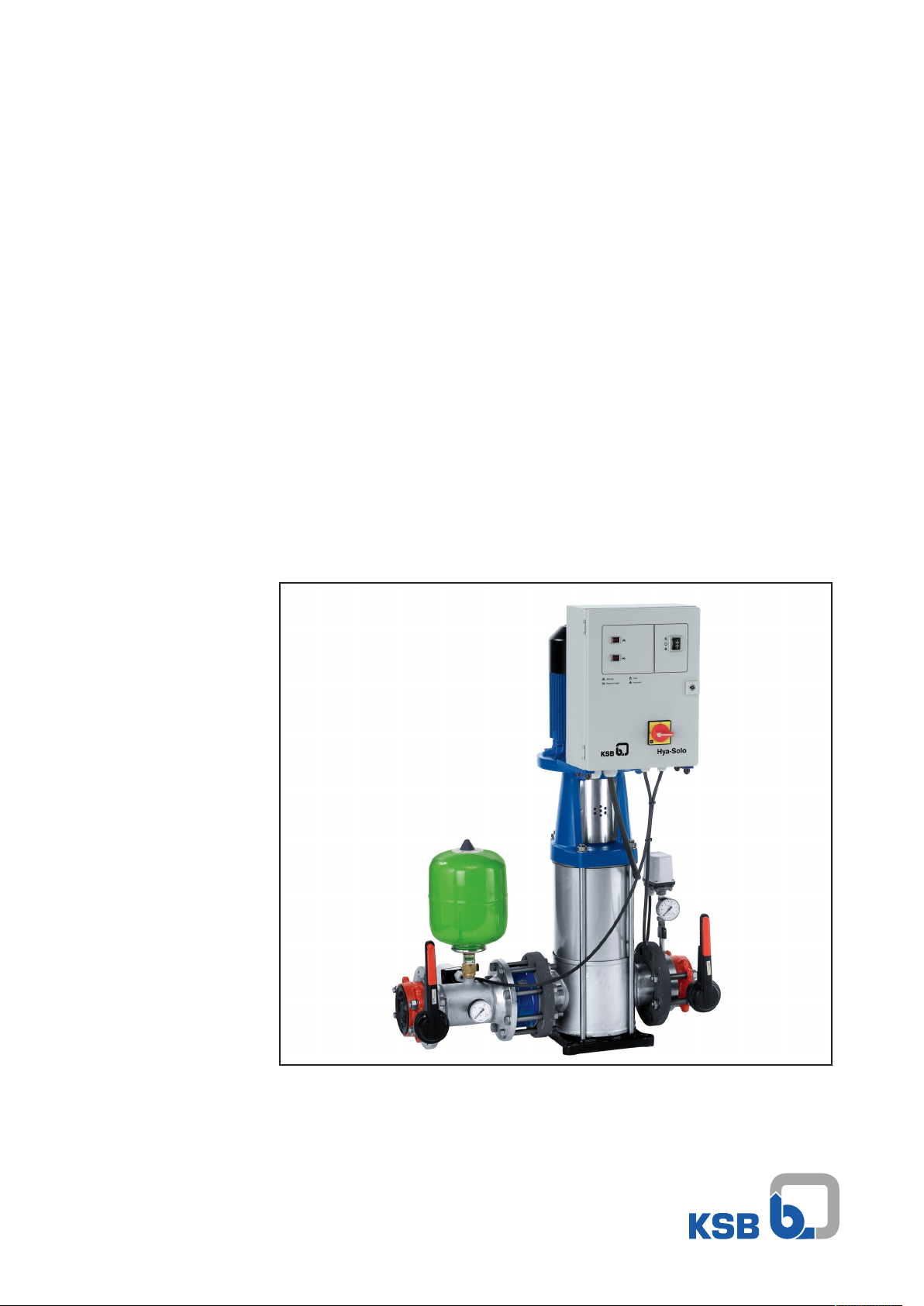
Pressure Booster System
Hya-Solo D
From Series 2014w33
Installation/Operating Manual
Page 2

Legal information/Copyright
Installation/Operating Manual Hya-Solo D
Original operating manual
All rights reserved. The contents provided herein must neither be distributed, copied, reproduced,
edited or processed for any other purpose, nor otherwise transmitted, published or made available to a
third party without the manufacturer's express written consent.
Subject to technical modification without prior notice.
© KSB SE & Co. KGaA, Frankenthal 18/12/2017
Page 3

Contents
Contents
Glossary .................................................................................................................................................. 5
1 General.................................................................................................................................................... 6
1.1 Principles ...........................................................................................................................................................6
1.2 Installation of partly completed machinery....................................................................................................6
1.3 Target group.....................................................................................................................................................6
1.4 Other applicable documents............................................................................................................................6
1.5 Symbols .............................................................................................................................................................6
2 Safety...................................................................................................................................................... 7
2.1 General..............................................................................................................................................................7
2.2 Intended use .....................................................................................................................................................7
2.3 Personnel qualification and personnel training.............................................................................................7
2.4 Consequences and risks caused by non-compliance with this manual .........................................................8
2.5 Safety awareness ..............................................................................................................................................8
2.6 Safety information for the operator/user.......................................................................................................8
2.7 Safety information for maintenance, inspection and installation ................................................................8
2.8 Unauthorised modes of operation..................................................................................................................9
3 Transport/Temporary Storage/Disposal............................................................................................. 10
3.1 Checking the condition upon delivery..........................................................................................................10
3.2 Transport.........................................................................................................................................................10
3.3 Storage/preservation......................................................................................................................................10
3.4 Return to supplier ..........................................................................................................................................11
3.5 Disposal ...........................................................................................................................................................11
4 Description............................................................................................................................................ 12
4.1 General description ........................................................................................................................................12
4.2 Designation.....................................................................................................................................................12
4.3 Name plate......................................................................................................................................................12
4.4 Design details..................................................................................................................................................12
4.5 Configuration and function...........................................................................................................................13
4.6 Noise characteristics .......................................................................................................................................14
4.7 Scope of supply...............................................................................................................................................14
4.8 Dimensions and weights ................................................................................................................................14
4.9 Terminal wiring diagram ...............................................................................................................................15
5 Installation at Site................................................................................................................................ 16
5.1 Installation ......................................................................................................................................................16
5.2 Checks to be carried out prior to installation...............................................................................................16
5.3 Installing the pressure booster system..........................................................................................................16
5.4 Installing the piping .......................................................................................................................................17
5.4.1 Fitting an expansion joint .................................................................................................................17
5.4.2 Installing a pressure reducer .............................................................................................................18
5.5 Installing unpressurised inlet tanks...............................................................................................................18
5.6 Fitting the dry running protection device ....................................................................................................19
5.7 Electrical connection ......................................................................................................................................19
6 Commissioning/Start-up/Shutdown................................................................................................... 20
6.1 Commissioning/Start-up.................................................................................................................................20
6.1.1 Prerequisites for commissioning/start-up .........................................................................................20
6.1.2 Commissioning/start-up of pressure booster system .......................................................................20
6.2 Switching on the pressure booster system....................................................................................................21
6.3 Checklist for commissioning/start-up ............................................................................................................22
6.4 Shutdown........................................................................................................................................................22
Hya-Solo D
3 of 36
Page 4

Contents
7 Operating the Pressure Booster System............................................................................................. 23
8 Servicing/Maintenance........................................................................................................................ 24
8.1 General information/Safety regulations .......................................................................................................24
8.1.1 Inspection contract ...........................................................................................................................25
8.2 Servicing/inspection........................................................................................................................................25
8.2.1 Supervision of operation ...................................................................................................................25
8.2.2 Checklist for inspection .....................................................................................................................25
8.2.3 Setting the pre-charge pressure........................................................................................................26
9 Trouble-shooting.................................................................................................................................. 27
10 Related Documents.............................................................................................................................. 29
10.1 List of components .........................................................................................................................................29
10.1.1 Hya-SoloD with Movitec 2, 4, 6, 10, 15 ............................................................................................ 29
10.1.2 Hya-SoloD with Movitec 25, 40, 60, 90 ............................................................................................ 30
11 EC Declaration of Conformity ............................................................................................................. 31
12 Certificate of Decontamination........................................................................................................... 32
13 Commissioning Report......................................................................................................................... 33
Index ..................................................................................................................................................... 34
4 of 36
Hya-Solo D
Page 5

Glossary
Glossary
Accumulator
The accumulator serves to compensate for
pressure losses in the piping system downstream
of the pressure booster system which may be
caused by the consumption of small quantities of
water. As a result, the frequency of starts of the
pressure booster system is minimised.
Automatic mode
The pump is started and stopped as a function of
pressure or via a contact at the wall hydrant.
Certificate of decontamination
A certificate of decontamination is enclosed by the
customer when returning the product to the
manufacturer to certify that the product has been
properly drained to eliminate any environmental
and health hazards arising from components in
contact with the fluid handled.
Dry running protection
Dry running protection devices prevent the pump
from being operated without the fluid to be
handled, which would result in pump damage.
Manual mode
In manual mode, the pressure booster system is
operated directly on mains power, independently
of the control unit.
Hya-Solo D
5 of 36
Page 6

1 General
1 General
1.1 Principles
This operating manual is supplied as an integral part of the type series and variants
indicated on the front cover. The manual describes the proper and safe use of this
equipment in all phases of operation.
The name plate indicates the type series/size, the main operating data and the order
number. The series/serial number uniquely identifies the pressure booster system and
serves as identification for all further business processes.
In the event of damage, immediately contact your nearest KSB service centre to
maintain the right to claim under warranty.
Noise characteristics see (ðSection4.6,Page14)
1.2 Installation of partly completed machinery
To install partly completed machinery supplied by KSB refer to the sub-sections under
Servicing/Maintenance.
1.3 Target group
This operating manual is aimed at the target group of trained and qualified specialist
technical personnel. (ðSection2.3,Page7)
1.4 Other applicable documents
Table1: Overview of other applicable documents
Document Contents
Sub-supplier product literature Operating manuals, logic diagram and other
product literature of accessories and integrated
machinery components
1.5 Symbols
Table2: Symbols used in this manual
Symbol Description
✓ Conditions which need to be fulfilled before proceeding with the
step-by-step instructions
⊳ Safety instructions
⇨ Result of an action
⇨ Cross-references
1.
2.
Step-by-step instructions
Note
Recommendations and important information on how to handle
the product
6 of 36
Hya-Solo D
Page 7

2 Safety
!
DANGER
2 Safety
All the information contained in this section refers to hazardous situations.
2.1 General
This manual contains general installation, operating and maintenance instructions
that must be observed to ensure safe operation of the pressure booster system and
prevent personal injury and damage to property.
The safety information in all sections of this manual must be complied with.
This manual must be read and completely understood by the responsible specialist
personnel/operators prior to installation and commissioning.
The contents of this manual must be available to the specialist personnel at the site
at all times.
Information attached directly to the pressure booster system must always be
complied with and be kept in a perfectly legible condition at all times. This applies
to, for example:
▪ Arrow indicating the direction of rotation
▪ Markings for connections
▪ Name plate
The operator is responsible for ensuring compliance with all local regulations which
are not taken into account in this manual.
2.2 Intended use
▪ The pressure booster system must only be operated within the operating limits
described in the other applicable documents.
▪ Only operate pressure booster systems which are in perfect technical condition.
▪ Do not operate partially assembled pressure booster systems.
▪ The pressure booster system must only handle the fluids described in the product
literature of the respective design variant.
▪ Never operate the pressure booster system without the fluid to be handled.
▪ Observe the information on minimum flow rates specified in the product
literature (to prevent overheating, bearing damage, etc).
▪ Observe the information on maximum flow rates specified in the product
literature (to prevent overheating, mechanical seal damage, cavitation damage,
bearing damage, etc).
▪ Do not throttle the flow rate on the suction side of the pressure booster system
(to prevent cavitation damage).
▪ Consult the manufacturer about any other modes of operation not described in
the product literature.
Prevention of foreseeable misuse
▪ Never exceed the permissible operating limits (pressure, temperature, etc.)
specified in the product literature.
▪ Observe all safety information and instructions in this manual.
2.3 Personnel qualification and personnel training
All personnel involved must be fully qualified to install, operate, maintain and
inspect the machinery this manual refers to.
The responsibilities, competence and supervision of all personnel involved in
installation, operation, maintenance and inspection must be clearly defined by the
operator.
Deficits in knowledge must be rectified by means of training and instruction
provided by sufficiently trained specialist personnel. If required, the operator can
commission the manufacturer/supplier to train the personnel.
Hya-Solo D
7 of 36
Page 8

2 Safety
Training on the pressure booster system must always be supervised by technical
specialist personnel.
2.4 Consequences and risks caused by non-compliance with this manual
▪ Non-compliance with this operating manual will lead to forfeiture of warranty
cover and of any and all rights to claims for damages.
▪ Non-compliance can, for example, have the following consequences:
– Hazards to persons due to electrical, thermal, mechanical and chemical
effects and explosions
– Failure of important product functions
– Failure of prescribed maintenance and servicing practices
– Hazard to the environment due to leakage of hazardous substances
2.5 Safety awareness
In addition to the safety information contained in this manual and the intended use,
the following safety regulations shall be complied with:
▪ Accident prevention, health and safety regulations
▪ Explosion protection regulations
▪ Safety regulations for handling hazardous substances
▪ Applicable standards, directives and laws
2.6 Safety information for the operator/user
▪ The operator shall fit contact guards for hot, cold and moving parts and check
that the guards function properly.
▪ Do not remove any contact guards during operation.
▪ Eliminate all electrical hazards. (In this respect refer to the applicable national
safety regulations and/or regulations issued by the local energy supply
companies.)
▪ If shutting down the pump does not increase potential risk, fit an emergency-
stop control device in the immediate vicinity of the pump (set) during pump set
installation.
2.7 Safety information for maintenance, inspection and installation
▪ Modifications or alterations of the pressure booster system are only permitted
with the manufacturer's prior consent.
▪ Use only original spare parts or parts authorised by the manufacturer. The use of
other parts can invalidate any liability of the manufacturer for resulting damage.
▪ The operator ensures that maintenance, inspection and installation is performed
by authorised, qualified specialist personnel who are thoroughly familiar with
the manual.
▪ Carry out work on the pressure booster system during standstill only.
▪ The pump casing must have cooled down to ambient temperature.
▪ Pump pressure must have been released and the pump must have been drained.
▪ When taking the pressure booster system out of service always adhere to the
procedure described in the manual.
▪ Decontaminate pressure booster systems which handle fluids posing a health
hazard.
▪ As soon as the work has been completed, re-install and/or re-activate any safety-
relevant and protective devices. Before returning the product to service, observe
all instructions on commissioning.
▪ Make sure the pressure booster system cannot be accessed by unauthorised
persons (e.g. children).
▪ Prior to opening the device, pull the mains plug and wait for at least 10minutes.
8 of 36
Hya-Solo D
Page 9

2 Safety
2.8 Unauthorised modes of operation
Always observe the limits stated in the product literature.
The warranty relating to the operating reliability and safety of the pressure booster
system supplied is only valid if the equipment is used in accordance with its intended
use. (ðSection2.2,Page7)
Hya-Solo D
9 of 36
Page 10
3 Transport/Temporary Storage/Disposal
3 Transport/Temporary Storage/Disposal
3.1 Checking the condition upon delivery
1. On transfer of goods, check each packaging unit for damage.
2. In the event of in-transit damage, assess the exact damage, document it and
notify KSB or the supplying dealer (as applicable) and the insurer about the
damage in writing immediately.
3.2 Transport
NOTE
The pressure booster system is bolted to a pallet and wrapped in plastic foil for
shipping and temporary storage. All connecting points are capped.
DANGER
Pressure booster system tipping over
Risk of injury by falling pressure booster system!
▷ Never suspend the pressure booster system by its power cable.
▷ Observe the applicable local accident prevention regulations.
▷ Pay attention to the weight data and the centre of gravity.
▷ Use suitable and permitted transporting equipment, e.g. crane, forklift or
elevating platform truck.
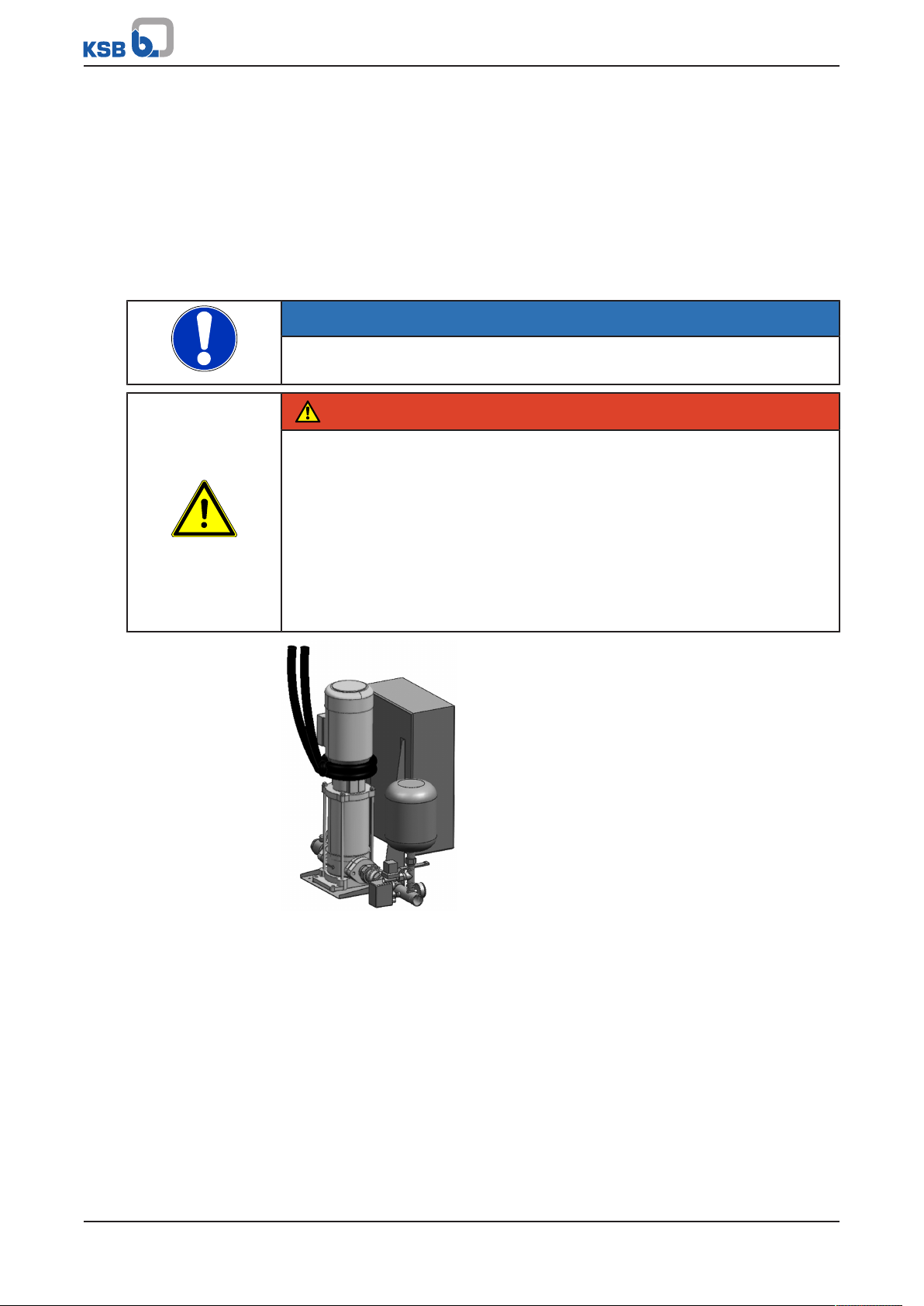
▷ Attach the pressure booster system to crane lifting tackle as shown, or use a
forklift or pallet truck to move the pallet.
10 of 36
Fig.1: Transporting the pressure booster system
ü The pressure booster system has been checked for in-transit damage.
1. Make sure the transport equipment is suitable for safely carrying the indicated
load.
2. Transport the pressure booster system to the place of installation.
3. Attach the pressure booster system to the lifting tackle as shown, lift it off the
pallet and dispose of the pallet.
4. Use suitable lifting equipment to lift the pressure booster system and carefully
put it down at the place of installation.
3.3 Storage/preservation
If commissioning is to take place some time after delivery, we recommend that the
following measures be taken when storing the pressure booster system:
Hya-Solo D
Page 11
3 Transport/Temporary Storage/Disposal
CAUTION
Damage during storage due to frost, moisture, dirt, UV radiation or vermin
Corrosion/contamination of pressure booster system!
▷ Store the pressure booster system in a frost-proof room. Do not store outdoors.
CAUTION
Wet, contaminated or damaged openings and connections
Leakage or damage of the pressure booster system!
▷ Only open the openings of the pressure booster system at the time of
installation.
Store the pressure booster system in a dry, protected room where the atmospheric
humidity is as constant as possible.
3.4 Return to supplier
1. Drain the pressure booster system as per operating instructions.
2. Always flush and clean the pressure booster system, particularly if it has been
used for handling noxious, explosive, hot or other hazardous fluids.
3. If the pressure booster system has handled fluids whose residues could lead to
corrosion damage in the presence of atmospheric humidity or could ignite upon
contact with oxygen, the pressure booster system must also be neutralised and
treated with anhydrous inert gas to ensure drying.
4. Always complete and enclose a certificate of decontamination when returning
the pressure booster system. (ðSection12,Page32)
Always indicate any safety and decontamination measures taken.
NOTE
If required, a blank certificate of decontamination can be downloaded from the
following web site: www.ksb.com/certificate_of_decontamination
3.5 Disposal
WARNING
Fluids, consumables and supplies which are hot and/or pose a health hazard
Hazard to persons and the environment!
▷ Collect and properly dispose of flushing fluid and any residues of the fluid
handled.
▷ Wear safety clothing and a protective mask if required.
▷ Observe all legal regulations on the disposal of fluids posing a health hazard.
1. Dismantle the pressure booster system.
Collect greases and other lubricants during dismantling.
2. Separate and sort the pump materials, e.g. by:
- Metals
- Plastics
- Electronic waste
- Greases and other lubricants
3. Dispose of materials in accordance with local regulations or in another
controlled manner.
Hya-Solo D
11 of 36
Page 12

4 Description
Auftrags-Nr.:
14w4102.rN-neireS:noitisoP6040/1 B/D oloS ayH
Förderstrom 4,0 m3/h Druckbehälter: Motorleistung P2 1 x 1,10 kW
Einschaltdruck (p
E
) 3,4 bar Vorpreßdruck 3,1 bar Betriebsspannung / Frequenz 400V 50 HZ Hz
Ausschaltdruck (p
A
) 4,8 bar Inhalt Bruttovolumen 8,0 Liter Steuerspannung / Frequenz 230 V 50HZ Hz
mortsnnenrotoMm3,43ehöhredröF
2,4 A
:.rN nalptlahcSm4,250=Q ieb ehöhredröF BD 706 990
Vordruck 0,0 bar
Betriebsdruck max. 16,0 bar
Ident Nr: xx xxx xxx Vor Inbetriebnahme Betriebsanleitung beachten ! ZNI 1448J
200
9972726833
6
4
8
7
1 2 3
5
9
101112
13
14
15
16
17
18
19
4 Description
4.1 General description
▪ Pressure booster system
4.2 Designation
Example: Hya-Solo D 04 05 2 - 4
Table3: Key to the designation
Code Description
Hya-Solo Pressure booster system with one pump
D Model with three-phase motor,
pressure-dependent starting and stopping
04 Pump size
05 Number of pump stages
2 - 4 Inlet pressure in bar
4.3 Name plate
Fig.2: Name plate (example)
1 Type series, size 2 Order item number
3 Order number 4 Series code
5 Motor power P2 6 Operating voltage/frequency
7 Control voltage/frequency 8 Nominal motor current
9 Circuit diagram 10 Gross vol. content
11 Pre-charge pressure 12 Accumulator
13 Maximum operating pressure 14 Inlet pressure
15 Head at Q=0 16 Head
17 Stop pressure 18 Start-up pressure
19 Flow rate
Key to the series code
Calendar year Week
2014 w33
4.4 Design details
Design
12 of 36
The pressure booster system consists of a non-self-priming multistage high-pressure
centrifugal pump with suction and discharge side shut-off valves. The shut-off valves
enable dismantling of the pump or check valve without draining the piping system.
The discharge-side check valve prevents backflow through the pump when the pump
Hya-Solo D
Page 13

4 Description
1
5
2
3
6
4
is not running and reduces the load on the mechanical seal.
An accumulator, a pressure switch and a pressure gauge are fitted on the discharge
side of the system.
The switchgear and controlgear assembly for pressure booster systems with Movitec
2, 4, 6, 10, 15, 25, 40 and 60 is mounted on the pump or baseplate and ready-wired
to the pressure booster system.
The switchgear and controlgear assembly for pressure booster systems with Movitec
90 is designed for wall mounting.
Anti-vibration mounts are fitted on the pump feet or baseplate.
4.5 Configuration and function
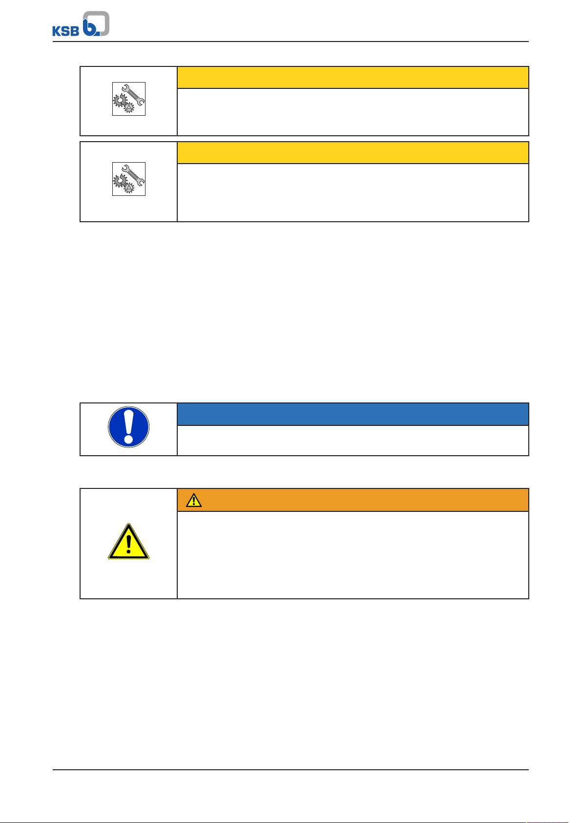
Fig.3: Hya-Solo D
1 Pump 2 Accumulator
3 Check valve 4 Pressure gauge
5 Control unit 6 Shut-off valve
Design
Function
Automatic mode
Function
Manual mode
The fully automatic pressure booster system is equipped with a non-self-priming
vertical high-pressure pump (1) for pumping the fluid handled to the consumer
installations in the set pressure range.
The pump is started and stopped as a function of pressure by a fully automatic
control unit. If the pressure drops below the set start-up pressure p
started up via the pressure switch.
When consumption decreases again, the pump is stopped as a function of pressure
after the set after-run period (up to 3 minutes).
The pressure booster system can also be controlled via External ON/OFF signals,
independently of the pressure switch.
A manual-0-automatic selector switch is provided at the switchgear and controlgear
assembly. When the switch is set to "manual", the pump operates directly on mains
power, independently of the automatic system (pressure switch or External ON/OFF).
NOTE
Continuous manual mode is reserved exclusively for emergencies!
Continuous operation of the pressure booster system in manual mode may result in
waste of energy and water.
In manual mode, a minimum flow (see table below) is essential to prevent the fluid
handled and the pump from overheating when no water is consumed at the
consumer installations.
, the pump is
start
Hya-Solo D
13 of 36
Page 14

Example
Function
Dry running protection
4 Description
Minimum flow for pump in manual mode
Table4: Minimum flow per pump in manual mode
Pump Minimum flow per pump in manual mode
[l/h]
Movitec 2B 200
Movitec 4B 400
Movitec 6B 600
Movitec 10B 1100
Movitec 15B 1600
Movitec 25B 2800
Movitec 40B 4600
Movitec 60B 6100
Movitec 90B 8500
An open 1/2-inch tap equals a water consumption of approx. 800 to 1,200 l/h.
The dry running protection function is active in automatic and manual mode.
A digital input is provided for connecting dry running protection equipment. When
the input is open, the control unit detects dry running and stops the pressure booster
system after approx. 10 seconds (factory setting).
4.6 Noise characteristics
For the noise level of the individual pumps please refer to the pump's operating
instructions.
4.7 Scope of supply
Depending on the model, the following items are included in the scope of supply:
Pressure booster system
▪ One Movitec vertical high-pressure centrifugal pump
▪ Check valve
▪ Shut-off valves
▪ Membrane-type direct-flow accumulator on the discharge side
▪ Pressure switch for the discharge side
▪ Vibration damping
▪ Pressure gauge for pressure indication
Control cabinet
▪ Indicator lamp for “Pump fault” (red)
▪ Indicator lamp for “Lack of water” (red)
▪ Motor protection switch, lockable
▪ Manual-0-automatic selector switch
▪ Terminal strip with markings for all connections
▪ Remote ON/OFF
▪ Contactor for DOL starting up to 4kW
▪ Star-delta starting for 5.5 kW and above
▪ Circuit diagram and list of electric components
▪ Volt-free contacts for operation, fault, lack of water
14 of 36
4.8 Dimensions and weights
For dimensions and weights refer to the outline drawings of the pressure booster
system.
Hya-Solo D
Page 15

4 Description
4.9 Terminal wiring diagram
For the terminal assignment refer to the circuit diagram.
Hya-Solo D
15 of 36
Page 16

5 Installation at Site
5 Installation at Site
5.1 Installation
Install pressure booster systems either in the technical equipment room or in a wellventilated, frost-free, lockable room used for no other purpose. No harmful gases are
allowed to enter the place of installation. An adequately sized floor drain (leading to
a sewer or equivalent) must be provided.
The pressure booster system is designed for a maximum ambient temperature of 0°C
to +40°C at a relative humidity of 50%.
NOTE
Do not install pressure booster systems next to sleeping or living quarters.
If expansion joints (KSB accessory) are used for damping vibrations, their fatigue
strength (endurance limit) must be given due consideration. Expansion joints must be
installed to allow quick and easy replacement.
5.2 Checks to be carried out prior to installation
Place of installation
WARNING
Installation on mounting surfaces which are unsecured and cannot support the
load
Personal injury and damage to property!
▷ Use a concrete of compressive strength class C12/15 which meets the
requirements of exposure class X0 to EN206-1.
▷ The mounting surface must have set and must be completely horizontal and
even.
▷ Observe the weights indicated.
NOTE
The anti-vibration mounts of the pressure booster system provide adequate
insulation against solid-borne noise.
1. Check the structural requirements.
All structural work required must have been prepared in accordance with the
dimensions stated in the outline drawing.
5.3 Installing the pressure booster system
WARNING
Top-heavy pressure booster system
Risk of personal injury by pressure booster system tilting!
▷ Pressure booster systems awaiting final installation must be secured against
tipping over.
▷ Firmly anchor the pressure booster system.
16 of 36
Remove all packaging before installing the pressure booster system. Connect the
pressure booster system's inlet line and discharge line to the corresponding site
distribution lines.
Hya-Solo D
Page 17

5 Installation at Site
NOTE
In order to avoid transmission of piping forces onto the pressure booster system
and transmission of solid-borne noise, we recommend installing length-limited
expansion joints.
Allow sufficient space for maintenance and repair work.
ü All structural work required has been checked.
ü The dimensions of the concrete foundation are correct, and the concrete has set
firmly.
1. Mark out the anchoring holes on the floor as shown in the outline drawing.
2. Drill the holes (max. diameter: 12mm).
3. Insert plug fixings of appropriate size.
4. Set the pressure booster system down in its correct installation position.
5. Use suitable bolts to firmly anchor the pressure booster system.
5.4 Installing the piping
Make sure that piping is installed without transmitting any stresses or strains. The use
of length-limited expansion joints (see accessories) is recommended.
CAUTION
Air pockets in suction line
Pressure booster system cannot prime!
▷ Lay piping with a continuously rising slope (as shown).
Suction lift operation
Incorrect Correct
NOTE
For suction lift operation install suitable swing check valves at the suction line ends
which are submerged in the fluid handled. Take into account the head losses
caused by these swing check valves.
Do not exceed the maximum suction lift of the pumps.
5.4.1 Fitting an expansion joint
DANGER
Sparks and radiant heat
Fire hazard!
▷ Take suitable precautions to protect the expansion joint if any welding work is
carried out nearby.
Hya-Solo D
17 of 36
Page 18

5 Installation at Site
CAUTION
Leaking expansion joint
Flooding of installation room!
▷ Regularly check for cracks or blisters, exposed fabric or other defects.
ü The expansion joint has a length limiter with solid-borne sound insulation so as
to be able to absorb reaction forces.
1. Install the expansion joint in the piping free of twist or distortion. Never use the
expansion joint to compensate for misalignment or mismatch of the piping.
2. Tighten the bolts evenly and crosswise during assembly. The ends of the bolts
must not protrude from the flange.
3. Do not apply paint to the expansion joint. Protect it from any contact with oil.
4. The position of the expansion joint within the pressure booster system must
allow easy access and inspection and it must, therefore, not be insulated along
with the piping.
5. Expansion joints are subject to wear.
5.4.2 Installing a pressure reducer
NOTE
A pipe length of approximately 600 mm must be provided on the inlet side to
accommodate a pressure reducer, if necessary.
NOTE
A pressure reducer must be installed
- if the inlet pressure fluctuation is too high for the pressure booster system to
operate as intended or
- if the total pressure (inlet pressure plus shut-off head) of the pressure booster
system exceeds the design pressure.
The maximum pump discharge pressure at zero flow point is reached in manual
mode.
A minimum pressure gradient of 5 metres is required for the pressure reducer to
fulfill its function. The pressure downstream of the pressure reducer (downstream
pressure) is the basic parameter for determining the pump head.
For example:
The inlet pressure fluctuates between 4 and 8 bar. A pressure reducer is needed
upstream of the pressure booster system on the inlet side.
Min. inlet pressure (p
Min. pressure gradient=0.5bar
Downstream pressure=3.5bar.
)=4bar
inl
18 of 36
5.5 Installing unpressurised inlet tanks
Installation and location of an unpressurised inlet tank together with the pressure
booster system are governed by the same rules applicable to the pressure booster
system.
Install the closed PE inlet tank (under atmospheric pressure) available as a KSB
accessory as described in the installation instructions supplied with the tank.
CAUTION
Contamination in the pressure booster system
Damage to the pumps!
▷ Clean the tank before filling it.
Hya-Solo D
Page 19

5 Installation at Site
The tank must be connected mechanically and electrically to the pressure booster
system prior to commissioning of the system.
5.6 Fitting the dry running protection device
Install the dry running protection device supplied together with the pressure booster
system as a separate, non-fitted accessory, or supplied at a later date for retrofitting,
in accordance with its operating instructions and connect it to the switchgear and
controlgear assembly.
The switchgear and controlgear assembly is provided with the requisite digital input.
The cut-out delay can be set at the time relay within a range from 5 to 100 seconds.
The factory setting is approx.10seconds.
5.7 Electrical connection
DANGER
Electrical connection work by unqualified personnel
Danger of death from electric shock!
▷ Always have the electrical connections installed by a trained and qualified
electrician.
▷ Observe regulations IEC60364.
WARNING
Incorrect connection to the mains
Damage to the mains network, short circuit!
▷ Observe the technical specifications of the local energy supply companies.
The circuit diagrams are included in the control cabinet of the pressure booster
system, where they must remain when not in use.
The product literature of the switchgear and controlgear assembly supplied with the
pressure booster system includes a list of the electrical components installed. When
ordering spare parts for electrical components, please always indicate the circuit
diagram number.
Hya-Solo D
19 of 36
Page 20

6 Commissioning/Start-up/Shutdown
6 Commissioning/Start-up/Shutdown
6.1 Commissioning/Start-up
6.1.1 Prerequisites for commissioning/start-up
Before commissioning/start-up of the pressure booster system make sure that the
following requirements are met:
▪ The pressure booster system has been properly connected to the electric power
supply and is equipped with all protection devices.
▪ All relevant VDE standards and/or regulations applicable in the country of use are
complied with.
▪ The dry running protection device has been installed.
CAUTION
Dry running of pump
Damage to the pump/pressure booster system!
▷ If no dry running protection device is connected when commissioning takes
place, pressure booster systems in manual or test run mode will be stopped
automatically after approx. 10 seconds. If the dry running protection terminal is
disabled by means of a bridge, the operator shall assume responsibility for any
dry running that might occur.
NOTE
The competent authorities must be informed in due time prior to commissioning/
test running the system.
6.1.2 Commissioning/start-up of pressure booster system
Commissioning should be carried out by specialist KSB staff.
NOTE
The pressure booster systems undergo hydraulic testing with water at the factory
and are drained carefully before shipment. However, for technical reasons the
presence of some residual water is unavoidable.
The hydraulic connections are closed in as-supplied condition. They must only be
opened immediately before installation.
Refer to EN806 before commissioning/starting up the pressure booster system.
After an extended pre-installation period, in particular, flushing or even
professional disinfection is recommended. For extensive or branched piping systems
the pressure booster system should preferably be flushed either before installation,
or flushing should be restricted to a limited area.
CAUTION
Foreign matter in the piping
Damage to the pump/pressure booster system!
▷ Before commissioning/starting (or even test running) the pressure booster
system, make sure that there is no foreign matter in the pressure booster
system or piping.
20 of 36
Hya-Solo D
Page 21

6 Commissioning/Start-up/Shutdown
NOTE
Commissioning of the pressure booster system - even test running - shall only be
carried out in full compliance with all pertinent VDE (German Association of
Electrical Engineers) regulations.
ü The pipe unions between the pump and the piping have been re-tightened.
ü The flange bolting has been checked for firm seating.
ü The cooling air inlet and outlet openings on the motor are unobstructed.
ü All shut-off valves of the pressure booster system are open.
ü The pre-charge pressure of the membrane-type accumulator has been checked.
(ðSection8.2.3,Page26)
1. Set the master switch to "0" and the manual-0-automatic selector switch to "0".
2. Provide connection to power supply.
3. Open/loosen the vent plugs on the pump (refer to the pump's installation and
operating instructions).
4. Slowly open the inlet-side shut-off element and prime the pressure booster
system until the fluid to be handled escapes through all vent holes.
5. Close and slightly tighten the pump vent plugs.
6. Switch on the master switch.
7. Set the pressure booster system to manual mode at the manual-0-automatic
selector switch and check the pump's direction of rotation. The direction of
rotation must match the rotation arrow on the motor. If the pump runs in the
wrong direction of rotation, interchange two phases at the motor terminal strip.
8. Set the pressure booster system to automatic mode, slowly open the discharge-
side shut-off element and observe the pressure gauge to check whether the
pressure booster system starts at the required start-up pressure.
If the start-up pressure has been set incorrectly, correct it as described in the
operating manual of the pressure switch.
9. Slowly close the discharge-side shut-off element and observe the pressure gauge
to check whether the pressure booster system stops at the required stop
pressure.
If the stop pressure has been set incorrectly, correct it as described in the
operating manual of the pressure switch. Set the required after-run time at the
time relay by adjusting the setting screw to a value between 1 and 3minutes.
10. Run the pump again, with the discharge-side shut-off element open, and loosen
the vent plug to let any remaining air escape.
11. Then re-tighten the vent plugs firmly.
12. Verify that the pump is running smoothly.
13. Close the discharge-side shut-off element in order to verify whether the pump
reaches its maximum shut-off head.
14. Connect the dry running protection device, if any, and check that it functions
properly.
15. Set the manual-0-automatic selector switch to automatic mode.
NOTE
Minor leakage of the mechanical seals during commissioning is normal and will
cease after a short period of operation.
6.2 Switching on the pressure booster system
Switch on the master switch to energise the pressure booster system.
Hya-Solo D
21 of 36
Page 22

6 Commissioning/Start-up/Shutdown
NOTE
The pressure booster system is factory-set to the start and stop pressures indicated
on the name plate.
6.3 Checklist for commissioning/start-up
Table5: Checklist
Operations Done
1 Read the operating instructions.
2 Check power supply and compare against the name plate data.
3 Check the earthing system (by measuring).
4 Check the mechanical connection to the water mains.
Re-tighten the flange bolting and pipe unions.
5 Prime and vent the pressure booster system from the inlet side.
6 Check inlet pressure.
7 Check whether all cables are still firmly connected to the terminals inside the control unit.
8 Check the direction of rotation.
9 Check the start and stop pressure; re-adjust, if necessary.
10 Test the proper function of the lack-of-water and dry running protection equipment. If not
fitted, make a relevant note in the commissioning report.
11 Vent the pump for a second time after it has been running for 5 to 10 minutes.
12 Set the switch to automatic.
13 Check the pre-charge pressure.
14 Record all system conditions that do not correspond to our specifications or to the purchase
order in the commissioning report (i.e. no dry running protection or inlet pressure + max.
pressure of pressure booster system higher than 16 bar).
15 Complete the commissioning report together with the operator/user and instruct the operator/
user as to the function of the system.
6.4 Shutdown
NOTE
As long as the pressure booster system is out of operation, water is supplied directly
at p
through the pressure booster system.
inl
Set the master switch to "0".
NOTE
Drain the pressure booster system for prolonged shutdown.
22 of 36
Hya-Solo D
Page 23

7 Operating the Pressure Booster System
7 Operating the Pressure Booster System
CAUTION
Incorrect operation
Water supply is not assured!
▷ Make sure to comply with all local regulations, particularly the EC Machinery
Directive and the EC Directive on Low-Voltage Equipment.
The pressure booster system is factory-set to the operating data indicated on the
name plate.
The settings can be modified via the control panel, if necessary.
Hya-Solo D
23 of 36
Page 24

8 Servicing/Maintenance
8 Servicing/Maintenance
8.1 General information/Safety regulations
The operator ensures that maintenance, inspection and installation is performed by
authorised, qualified specialist personnel who are thoroughly familiar with the
manual.
DANGER
Unintentional start-up of pressure booster system
Danger to life!
▷ The pressure booster system must be de-energised before repair or
maintenance work is carried out.
Switching off the motor protection switch will not de-energise the motor
power cables reliably.
WARNING
Improper lifting/moving of heavy assemblies or components
Personal injury and damage to property!
▷ Use suitable transport devices, lifting equipment and lifting tackle to move
heavy assemblies or components.
WARNING
Unintentional start-up of pressure booster system
Risk of injury by moving parts!
▷ Make sure the pressure booster system has been de-energised before
commencing work on the pressure booster system.
▷ Make sure that the pressure booster system cannot be started up
unintentionally.
WARNING
Unqualified personnel performing work on the pressure booster system
Risk of personal injury!
▷ Always have repair and maintenance work performed by specially trained,
qualified personnel.
CAUTION
Incorrectly serviced pressure booster system
Function of pressure booster system not guaranteed!
▷ Regularly service the pressure booster system.
▷ Prepare a maintenance schedule for the pressure booster system, with special
emphasis on lubricants, shaft seals and pump couplings.
24 of 36
Observe the general safety instructions and information.
Observe the operating manual of the pump when performing work on the pumps.
In the event of damage you can always contact our service staff.
A regular maintenance schedule will help avoid expensive repairs and contribute to
trouble-free, reliable operation of the pressure booster system with a minimum of
maintenance expenditure and work.
Never use force when dismantling and re-assembling the pressure booster system.
Hya-Solo D
Page 25

8 Servicing/Maintenance
8.1.1 Inspection contract
For all inspection and servicing work to be carried out at regular intervals we
recommend taking out the inspection contract offered by KSB. Contact your Service
Partner for details.
Checklist for commissioning/inspection and maintenance (ðSection6.3,Page22)
8.2 Servicing/inspection
8.2.1 Supervision of operation
CAUTION
Increased wear due to dry running
Damage to the pump set!
▷ Never operate the pump set without liquid fill.
▷ Never close the shut-off element in the suction line and/or supply line during
pump operation.
CAUTION
Impermissibly high temperature of fluid handled
Damage to the pump!
▷ Prolonged operation against a closed shut-off element is not permitted
(heating up of the fluid).
▷ Observe the temperature limits in the data sheet and in the section on
operating limits.
While the system is in operation, observe and check the following:
▪ Verify the start-up pressure of the pumps (at the pressure gauge).
▪ Compare the pre-charge pressure of the accumulator with the recommended
data. (ðSection8.2.3,Page26)
Close the shut-off elements under the accumulator and drain the accumulator via
the drain valve.
Remove the protective cap of the accumulator valve and check the pre-charge
pressure with the aid of a tyre pressure gauge.
Add nitrogen as necessary.
WARNING
Wrong gas
Danger of poisoning!
▷ Use only nitrogen to charge the accumulator.
▪ Check the rolling element bearings for running noises.
Vibrations, noise and an increase in current input occurring during unchanged
operating conditions indicate wear.
▪ Check the correct functioning of any auxiliary connections.
8.2.2 Checklist for inspection
In the event that you decide to conduct your own inspections, proceed according to
the following checklist at least once a year:
1. Check the pump and drive for smooth running and the mechanical seal for
integrity.
2. Check the flexible transmission elements for signs of wear.
3. Check the shut-off, drain and check valves for proper functioning and tightness.
4. Clean the strainer in the pressure reducer (if applicable).
Hya-Solo D
25 of 36
Page 26

8 Servicing/Maintenance
5. Check expansion joints for wear (if applicable).
6. Verify the pre-charge pressure level and check the accumulator for integrity, if
required. (ðSection8.2.3,Page26)
7. Check the automatic switching functionality.
8. Check the start and stop points of the pressure booster system.
9. Check the correct function of the overall system and compare its performance
with the name plate data.
10. Check the water inflow, inlet pressure, lack-of-water monitoring, flow
monitoring and pressure reducer.
11. Check the inlet tank and the float valve (if applicable). Check the overflow for
integrity and cleanliness.
8.2.3 Setting the pre-charge pressure
WARNING
Wrong gas
Danger of poisoning!
▷ Use only nitrogen to charge the accumulator.
The pre-charge pressure in the accumulator should be set to a value below the set
start-up pressure.
The setting can be effected via a valve located under the cover at the top of the
accumulator.
Example: Pre-charge pressure 10% lower than start-up pressure
Pre-charge pressure of accumulator p=0.9xp
p
= start-up pressure of pressure booster system
start
start
Recommendation
The stated values are average values. Tests on accumulators have shown that the best
storage volumes are achieved with the following factors:
pressures >3bar: factor0.9 and
pressures <3bar: factor0.8
Example:
p
= 5 bar: pre-charge pressure 5x0.9=4.5bar
start
p
=2bar: pre-charge pressure 2x0.8=1.6bar
start
CAUTION
Pre-charge pressure too high
Damage to accumulator!
▷ Observe data provided by accumulator manufacturer (see name plate or
operating manual of accumulator).
26 of 36
Hya-Solo D
Page 27

9 Trouble-shooting
9 Trouble-shooting
WARNING
Improper work to remedy faults
Risk of injury!
▷ For any work to remedy faults observe the relevant information in this manual
or in the relevant accessory manufacturer's product literature.
NOTE
Before performing any work on the pump's internal parts during the warranty
period please always consult the manufacturer. Our after-sales service will be at
your disposal. Non-compliance will lead to forfeiture of any and all rights to claims
for damages.
If problems occur that are not described in the following table, consultation with the
KSB customer service is required.
Pump cuts out shortly after start-up in manual mode. Red indicator lamp signals lack
A
of water.
Pressure booster system does not start up.
B
Pump running but not delivering water
C
Insufficient delivery of pressure booster system.
D
Discharge-side pressure too low.
E
Discharge-side pressure too high.
F
Leakage at mechanical seal.
G
Motor/pump overheated.
H
Motor protection switch triggered. Yellow indicator lamp is on.
I
Pump does not stop.
J
Pump starts too often (more than 30 start-ups per hour).
K
Table6: Trouble-shooting
A B C D E F G H I J K Possible cause Remedy
- - ✘ ✘ - - - ✘ - ✘ - Pump or piping are not completely
vented or primed.
✘ ✘ ✘ ✘ ✘ - - ✘ - - - Shut-off valves (partially) closed Check, open as necessary.
✘ - - ✘ ✘ - - - - ✘ - Strainer / dirt trap clogged Clean.
- - ✘ ✘ ✘ ✘ - - - - - Inlet-side shut-off valve closed Check, open as necessary.
- - - - - - - ✘ - ✘ - Discharge-side shut-off valve closed or
defective
✘ - - ✘ ✘ - - ✘ - ✘ - Inlet pressure lower than stated in the
purchase order
- ✘ - - - ✘ - - - - - Inlet pressure higher than stated in
the purchase order
- - - - - - - - - ✘ - Start-up pressure set too high Check setting.
- - - - - - - ✘ - - ✘ Pre-charge pressure of the
accumulator too low
- - - - - - - ✘ - - ✘ Defective accumulator Check integrity/replace, if necessary.
- - - - - - ✘ - - - - Defective mechanical seal Replace.
✘ - - - - - - - - - - Suction-side pressure switch set
incorrectly or defective
Vent and/or prime.
Check, open as necessary.
Contact KSB.
Contact KSB.
Restore nitrogen cushion.
Check setting.
1)
1) The pump pressure must be released before attempting to remedy faults on parts which are subjected to pressure.
Disconnect the pump from the power supply!
Hya-Solo D
27 of 36
Page 28

9 Trouble-shooting
A B C D E F G H I J K Possible cause Remedy
- - ✘ ✘ ✘ - - ✘ ✘ ✘ - Defective check valve in the pressure
booster system
- - - - ✘ - - - ✘ ✘ ✘ Water extraction higher than stated
Check, replace sealing element as
necessary.
Contact KSB.
1)
in the purchase order
- - - - - - - - ✘ - - Motor protection switch triggered or
set incorrectly, or pump seized
Compare setting with the motor's
rating plate data.
- - - - - - - - - - ✘ Delay setting too short Check setting.
- ✘ - - - - - - - - - Mains supply interrupted Check and remedy defect/check fuse.
- ✘ - - - - - - ✘ - - Main fuse on (owner-supplied)
distribution board loose or blown;
Check fuses and replace as necessary.
Measure the motor current.
fuses possibly too small or too fast
- ✘ - - - - - - - - - Phase failure Check individual phases; replace fuse,
if necessary.
✘ - - - - - - - - - - Inlet tank empty or float switch
Check and remedy defect.
defective/disconnected
28 of 36
Hya-Solo D
Page 29

10 Related Documents
82-1
655
591
743.2
691
743.1
742
838
743.1
82-1 655
591
743.2
691
743.1
742
838
743.1
10 Related Documents
10.1 List of components
10.1.1 Hya-SoloD with Movitec 2, 4, 6, 10, 15
Fig.4: General assembly drawing of Hya-Solo D with Movitec 2, 4, 6, 10
Fig.5: General assembly drawing of Hya-Solo D with Movitec 15
Table7: Spare parts for Hya-SoloD with Movitec 2, 4, 6, 10, 15
Part No. Description Ident. No.
591 Accumulator 01 079 764
655 Pump
691 Pressure gauge, discharge side 00 401 413
742 Lift check valve1 (Movitec 2, 4) 01 149 253
742 Lift check valve11/4 (Movitec 6) 01 149 254
742 Lift check valve11/2 (Movitec 10) 01 149 255
742 Lift check valve2 (Movitec 15) 01 149 256
743.1 Ball valve1 (Movitec 2, 4) 01 057 427
743.1 Ball valve11/4 (Movitec 6) 01 057 428
743.1 Ball valve11/2 (Movitec 10) 01 057 429
743.1 Ball valve2 (Movitec 15) 01 057 430
743.2 Ball valve (make Reflex) 01 079 765
82-1 Control unit On request
838 Pressure switch MCS 22 01 049 356
Hya-Solo D
29 of 36
Page 30

10 Related Documents
82-1
655
591
691 747746
743.2
838 746
For electric parts refer to the circuit diagram in the Annex.
NOTE
Pump spare parts correspond to Movitec in standard design (with oval flange).
10.1.2 Hya-SoloD with Movitec 25, 40, 60, 90
Fig.6: General assembly drawing of Hya-SoloD with Movitec 25, 40, 60, 90
Table8: Spare parts for Hya-SoloD with Movitec 25, 40, 60, 90
Part No. Description Ident. No.
591 Accumulator 01 079 764
655 Pump
691 Pressure gauge, discharge side 00 401 413
743.2 Ball valve (make Reflex) 01 079 765
746 Butterfly valve DN65 (Movitec 25) 40 982 350
746 Butterfly valve DN80 (Movitec 40) 40 982 351
746 Butterfly valve DN100 (Movitec 60, 90) 40 982 352
747 Swing check valve DN65 (Movitec 25) 01 086 243
747 Swing check valve DN80 (Movitec 40) 01 056 931
747 Swing check valve DN100 (Movitec 60, 90) 01 087 142
82-1 Control unit (not shown) On request
838 Pressure switch MCS 22 01 049 356
For electric parts refer to the circuit diagram in the Annex.
Non-documented parts on request (please indicate serial No. or order No.)
NOTE
Pump spare parts correspond to Movitec in standard design (with round flange).
30 of 36
Hya-Solo D
Page 31

11 EC Declaration of Conformity
11 EC Declaration of Conformity
Manufacturer: KSB SE & Co. KGaA
Johann-Klein-Straße 9
67227 Frankenthal (Germany)
The manufacturer herewith declares that the product:
Hya-Solo D
KSB order number: ...................................................................................................
▪ is in conformity with the provisions of the following Directives as amended from time to time:
– Pump (set): Machinery Directive 2006/42/EC
The manufacturer also declares that
▪ the following harmonised international standards have been applied:
– ISO 12100
– EN 809
▪ Applied national technical standards and specifications, in particular:
– DIN 1988-500
Person authorised to compile the technical file:
Dr Frank Obermair
Technical Project Manager Product Development Pump Systems and Drives
KSB SE & Co. KGaA
Johann-Klein-Straße 9
67227 Frankenthal (Germany)
The EU Declaration of Conformity was issued in/on:
Place, date
..............................2).............................
Name
Function
Company
Address
2) A signed, legally binding EU Declaration of Conformity is supplied with the product.
Hya-Solo D
31 of 36
Page 32

12 Certificate of Decontamination
12 Certificate of Decontamination
Type: ................................................................................................................................
Order number/
Order item number3): ................................................................................................................................
Delivery date: ................................................................................................................................
Field of application: ................................................................................................................................
Fluid handled3): ................................................................................................................................
Please tick where applicable3):
Radioactive Explosive Corrosive Toxic
Harmful Bio-hazardous Highly flammable Safe
Reason for return3): ................................................................................................................................
Comments: ................................................................................................................................
................................................................................................................................
The product/accessories have been carefully drained, cleaned and decontaminated inside and outside prior to dispatch/
placing at your disposal.
We herewith declare that this product is free from hazardous chemicals, biological and radioactive substances.
For mag-drive pumps, the inner rotor unit (impeller, casing cover, bearing ring carrier, plain bearing, inner rotor) has been
removed from the pump and cleaned. In cases of containment shroud leakage, the outer rotor, bearing bracket lantern,
leakage barrier and bearing bracket or intermediate piece have also been cleaned.
For canned motor pumps, the rotor and plain bearing have been removed from the pump for cleaning. In cases of leakage at
the stator can, the stator space has been examined for fluid leakage; if fluid handled has penetrated the stator space, it has
been removed.
No special safety precautions are required for further handling.
The following safety precautions are required for flushing fluids, fluid residues and disposal:
...............................................................................................................................................................
...............................................................................................................................................................
We confirm that the above data and information are correct and complete and that dispatch is effected in accordance with the
relevant legal provisions.
.................................................................... ....................................................... .......................................................
Place, date and signature Address Company stamp
3) Required fields
32 of 36
Hya-Solo D
Page 33

13 Commissioning Report
13 Commissioning Report
The KSB pressure booster system specified below was today commissioned by the undersigned authorised KSB
customer service engineer who created this report.
Pressure booster system details
Type series ........................................................................................................................................
Size ........................................................................................................................................
Serial number ........................................................................................................................................
Order No. ........................................................................................................................................
Purchaser/place of installation
Purchaser Place of installation
Name .................................................... ..........................................................................
Address .................................................... ..........................................................................
.................................................... ..........................................................................
Operating data For further details please refer to the circuit diagram.
Start-up pressure p
Inlet pressure monitoring p
(setting of inlet pressure switch)
Stop pressure p
Inlet pressure p
Pre-charge pressure of
accumulator p
bar ....................................................
start
- x
....................................................
inl
bar ....................................................
stop
bar ....................................................
inl
pre-charge
....................................................
bar
The system operator/operator's representative herewith confirms to have received instructions on how to operate
and service the pressure booster system. The relevant circuit diagrams and operating instructions have been
handed over.
Non-conformities found during commissioning Deadline for remedial action
Non-conformities 1 ........................................................................... ..........................................................................
............................................................................................................. ..........................................................................
............................................................................................................. ..........................................................................
............................................................................................................. ..........................................................................
Name of KSB representative Name of purchaser or representative
............................................................................................................. ..........................................................................
Place Date
............................................................................................................. ..........................................................................
Hya-Solo D
33 of 36
Page 34

Index
Index
A
After-run time21
C
Certificate of decontamination32
Commissioning/Start-up20
D
Design12
Disposal11
Dry running protection20, 21
F
Faults
Causes and remedies27
I
Installation at site16
Intended use7
L
List of spare parts29, 30
M
Misuse7
O
Operating limits7
Other applicable documents6
P
Partly completed machinery6
R
Return to supplier11
S
Safety7
Safety awareness8
Scope of supply14
Setting the start-up pressure21
Setting the stop pressure21
34 of 36
Hya-Solo D
Page 35

Page 36

KSB SE & Co. KGaA
Johann-Klein-Straße 9 • 67227 Frankenthal (Germany)
Tel. +49 6233 86-0
www.ksb.com
1951.831/05-EN (01201915)
 Loading...