

Page 1
Rainwater Harvesting System
Hya-Rain/Hya-Rain N
Installation/Operating Manual
Page 2

Legal information/Copyright
Installation/Operating Manual Hya-Rain/Hya-Rain N
Original operating manual
All rights reserved. The contents provided herein must neither be distributed, copied, reproduced,
edited or processed for any other purpose, nor otherwise transmitted, published or made available to a
third party without the manufacturer's express written consent.
Subject to technical modification without prior notice.
© KSB SE & Co. KGaA, Frankenthal 21/01/2019
Page 3

Contents
Contents
Glossary .................................................................................................................................................. 5
1 General.................................................................................................................................................... 6
1.1 Principles ...........................................................................................................................................................6
1.2 Target group.....................................................................................................................................................6
1.3 Other applicable documents............................................................................................................................6
1.4 Symbols .............................................................................................................................................................6
1.5 Key to safety symbols/markings.......................................................................................................................7
2 Safety...................................................................................................................................................... 8
2.1 General..............................................................................................................................................................8
2.2 Intended use .....................................................................................................................................................8
2.3 Personnel qualification and training...............................................................................................................9
2.4 Consequences and risks caused by non-compliance with these operating instructions ..............................9
2.5 Safety awareness ..............................................................................................................................................9
2.6 Safety information for the operator/user.......................................................................................................9
2.7 Safety information for maintenance, inspection and installation ................................................................9
2.8 Unauthorised modes of operation..................................................................................................................9
3 Transport/Temporary Storage/Disposal............................................................................................. 11
3.1 Checking the condition upon delivery..........................................................................................................11
3.2 Transport.........................................................................................................................................................11
3.3 Storage/preservation......................................................................................................................................12
3.4 Return to supplier...........................................................................................................................................12
3.5 Disposal ...........................................................................................................................................................13
4 Description............................................................................................................................................ 14
4.1 General description ........................................................................................................................................14
4.2 Designation.....................................................................................................................................................14
4.3 Name plate......................................................................................................................................................14
4.4 Design details..................................................................................................................................................15
4.5 Configuration and function...........................................................................................................................16
4.6 Noise characteristics .......................................................................................................................................17
4.7 Scope of supply...............................................................................................................................................17
4.8 Dimensions and weights ................................................................................................................................17
5 Installation at Site................................................................................................................................ 18
5.1 Safety regulations...........................................................................................................................................18
5.2 Checks to be carried out prior to installation...............................................................................................18
5.3 Setting up and installing the system.............................................................................................................18
5.4 Connecting the piping ...................................................................................................................................19
5.4.1 Connecting the mains water inlet ....................................................................................................19
5.4.2 Connecting the inlet line...................................................................................................................20
5.4.3 Connecting the discharge line ..........................................................................................................20
5.4.4 Connecting the overflow...................................................................................................................21
5.5 Electrical connection ......................................................................................................................................22
5.5.1 Connecting the float switch ..............................................................................................................22
5.5.2 Connecting the level control system.................................................................................................24
5.5.3 Connecting a booster pump (optional) ............................................................................................25
5.5.4 Connecting the system ......................................................................................................................27
6 Commissioning/Start-up/Shutdown................................................................................................... 28
6.1 Commissioning/Start-up.................................................................................................................................28
6.1.1 Prerequisites for commissioning/start-up .........................................................................................28
6.1.2 Priming and venting the system .......................................................................................................28
6.1.3 Start-up...............................................................................................................................................29
6.1.4 Functional test....................................................................................................................................29
6.2 Operating limits..............................................................................................................................................30
Hya-Rain/Hya-Rain N
3 of 64
Page 4

Contents
6.2.1 Ambient conditions ...........................................................................................................................30
6.2.2 Maximum operating pressure ...........................................................................................................30
6.2.3 Fluid handled .....................................................................................................................................30
6.3 Shutdown/storage/preservation ....................................................................................................................31
6.3.1 Measures to be taken for shutdown ................................................................................................31
6.3.2 Stopping the system ..........................................................................................................................31
7 Operation.............................................................................................................................................. 32
7.1 Control panel..................................................................................................................................................32
7.2 Mode of operation.........................................................................................................................................33
7.2.1 Automatic mode ................................................................................................................................33
7.2.2 Mains water mode (manual mode) ..................................................................................................33
7.2.3 Rainwater mode (manual mode) ......................................................................................................33
7.2.4 Priming ...............................................................................................................................................34
7.3 Level control system (Hya-Rain N only).........................................................................................................35
7.3.1 Calibrating the level control system/ setting the rainwater storage tank design ........................36
7.3.2 Setting the switching level for the rainwater storage tank............................................................37
7.3.3 Setting and displaying the rainwater storage tank water replacement ........................................38
7.3.4 Setting the valve switchover .............................................................................................................39
8 Servicing/Maintenance........................................................................................................................ 40
8.1 General information/safety regulations........................................................................................................40
8.2 Maintenance/inspection.................................................................................................................................41
8.2.1 Replacing the stored mains water ...................................................................................................41
8.2.2 Checking the mains water mode ......................................................................................................41
8.2.3 Checking the pump control unit.......................................................................................................42
8.2.4 Checking the discharge lines.............................................................................................................42
8.3 Drainage/cleaning ..........................................................................................................................................42
8.4 Dismantling the system..................................................................................................................................42
8.4.1 Removing the pump set from the piping.........................................................................................42
8.4.2 Removing the pump control unit .....................................................................................................44
8.4.3 Removing the mechanical seal..........................................................................................................46
8.5 Reassembling the system ...............................................................................................................................47
8.5.1 Installing the mechanical seal ...........................................................................................................47
8.5.2 Installing the pump control unit.......................................................................................................48
8.5.3 Installing the pump set......................................................................................................................49
9 Trouble-shooting.................................................................................................................................. 51
10 Related Documents.............................................................................................................................. 53
10.1 General assembly drawing with list of components ....................................................................................53
10.2 Exploded view with list of components (pump)...........................................................................................54
10.3 Dimensions and connections .........................................................................................................................56
10.3.1 Hya-Rain / Hya-Rain N........................................................................................................................56
10.3.2 Connections........................................................................................................................................57
10.4 Drilling pattern for wall mounting ...............................................................................................................57
10.5 Wiring diagrams .............................................................................................................................................58
10.5.1 Hya-Rain .............................................................................................................................................58
10.5.2 Hya-Rain N..........................................................................................................................................59
11 EU Declaration of Conformity............................................................................................................. 61
12 Certificate of Decontamination........................................................................................................... 62
Index ..................................................................................................................................................... 63
4 of 64
Hya-Rain/Hya-Rain N
Page 5

Glossary
Glossary
Certificate of decontamination
A certificate of decontamination is enclosed by the
customer when returning the product to the
manufacturer to certify that the product has been
properly drained to eliminate any environmental
and health hazards arising from components in
contact with the fluid handled.
Rainwater storage tank
Tank for collecting rainwater, for buried
installation or above-floor installation
Hya-Rain/Hya-Rain N
5 of 64
Page 6
1 General
1 General
1.1 Principles
This operating manual is valid for the type series and variants indicated on the front
cover.
The operating manual describes the proper and safe use of this equipment in all
phases of operation.
The name plate indicates the type series, the main operating data and the serial
number. The serial number uniquely describes the product and is used as
identification in all further business processes.
In the event of damage, immediately contact your nearest KSB Service centre to
maintain the right to claim under warranty.
1.2 Target group
This operating manual is aimed at the target group of trained and qualified specialist
technical personnel. (ðSection2.3,Page9)
1.3 Other applicable documents
Table1: Overview of other applicable documents
Document Contents
Sub-supplier product literature Operating manuals, logic diagram and other
product literature of accessories and integrated
machinery components
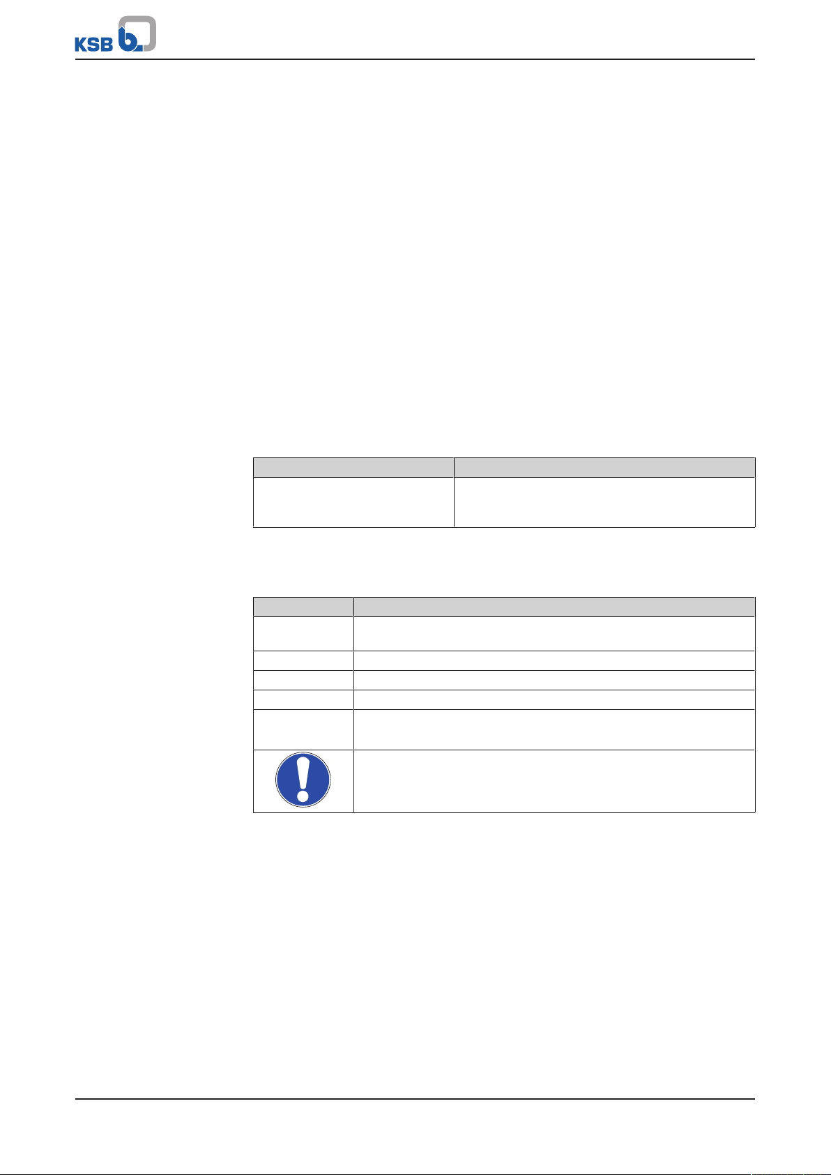
1.4 Symbols
Table2: Symbols used in this manual
Symbol Description
✓ Conditions which need to be fulfilled before proceeding with the
step-by-step instructions
⊳ Safety instructions
⇨
⇨ Cross-references
1.
2.
Result of an action
Step-by-step instructions
Note
Recommendations and important information on how to handle
the product
6 of 64
Hya-Rain/Hya-Rain N
Page 7
1 General
!
DANGER
!
WARNING
CAUTION
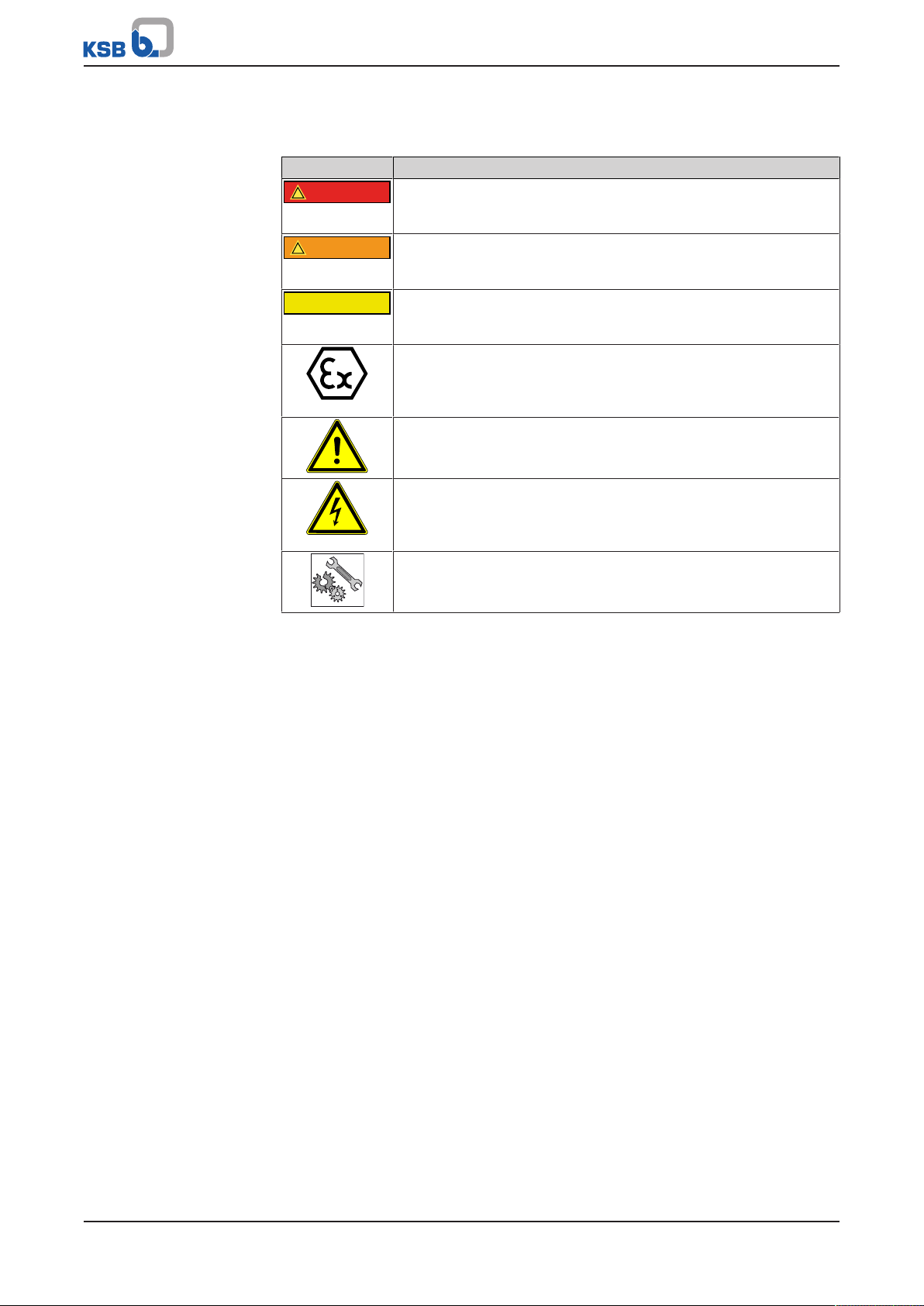
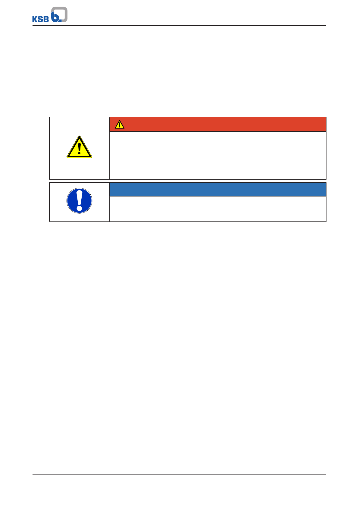
1.5 Key to safety symbols/markings
Table3: Definition of safety symbols/markings
Symbol Description
DANGER
This signal word indicates a high-risk hazard which, if not avoided,
will result in death or serious injury.
WARNING
This signal word indicates a medium-risk hazard which, if not
avoided, could result in death or serious injury.
CAUTION
This signal word indicates a hazard which, if not avoided, could
result in damage to the machine and its functions.
Explosion protection
This symbol identifies information about avoiding explosions in
potentially explosive atmospheres in accordance with EU Directive
2014/34/EU (ATEX).
General hazard
In conjunction with one of the signal words this symbol indicates a
hazard which will or could result in death or serious injury.
Electrical hazard
In conjunction with one of the signal words this symbol indicates a
hazard involving electrical voltage and identifies information about
protection against electrical voltage.
Machine damage
In conjunction with the signal word CAUTION this symbol indicates
a hazard for the machine and its functions.
Hya-Rain/Hya-Rain N
7 of 64
Page 8

2 Safety
!
DANGER
2 Safety
All the information contained in this section refers to hazardous situations.
In addition to the present general safety information the action-related safety
information given in the other sections must be observed.
2.1 General
▪ This operating manual contains general installation, operating and maintenance
instructions that must be observed to ensure safe operation of the system and
prevent personal injury and damage to property.
▪ Comply with all the safety instructions given in the individual sections of this
operating manual.
▪ The operating manual must be read and understood by the responsible specialist
personnel/operators prior to installation and commissioning.
▪ The contents of this operating manual must be available to the specialist
personnel at the site at all times.
▪ Information and markings attached directly to the product must always be
complied with and kept in a perfectly legible condition at all times. This applies
to, for example:
– Arrow indicating the direction of rotation
– Markings for connections
– Type designation
▪ The operator is responsible for ensuring compliance with all local regulations not
taken into account.
2.2 Intended use
▪ The system must only be operated within the operating limits described in the
other applicable documents.
▪ Only operate systems which are in perfect technical condition.
▪ Do not operate partially assembled systems.
▪ The system may only handle the fluids described in the product literature of the
relevant design variant.
▪ Never operate the system without the fluid to be handled.
▪ Observe the information on minimum flow rates specified in the product
literature (to prevent overheating, bearing damage, etc).
▪ Observe the maximum flow rates indicated in the data sheet or product
literature (to prevent overheating, cavitation damage, bearing damage, etc).
▪ Do not throttle the flow rate on the suction side of the system.
▪ Consult the manufacturer about any other modes of operation not described in
the product literature.
Prevention of foreseeable misuse
▪ Never exceed the permissible application and operating limits specified in the
product literature regarding pressure, temperature, etc.
▪ Observe all safety information and instructions in this manual.
8 of 64
Hya-Rain/Hya-Rain N
Page 9

2 Safety
2.3 Personnel qualification and training
All personnel involved must be fully qualified to install, operate, maintain and
inspect the equipment this manual refers to.
The responsibilities, competence and supervision of all personnel involved in
transport, installation, operation, maintenance and inspection must be clearly
defined by the operator.
Deficits in knowledge must be rectified by means of training and instruction
provided by sufficiently trained specialist personnel. If required, the operator can
commission the manufacturer/supplier to train the personnel.
Training at the system must always be supervised by the technical specialist
personnel.
2.4 Consequences and risks caused by non-compliance with these operating instructions
▪ Non-compliance with this operating manual will lead to forfeiture of warranty
cover and of any and all rights to claims for damages.
▪ Non-compliance can, for example, have the following consequences:
– Hazard to persons by electrical, thermal and mechanical effects
– Failure of important product functions
– Failure of prescribed maintenance and servicing practices
2.5 Safety awareness
In addition to the safety information contained in this operating manual and the
intended use, the following safety regulations shall be complied with:
▪ Accident prevention, health regulations and safety regulations
▪ Safety regulations for handling hazardous substances
▪ Applicable standards, directives and laws
2.6 Safety information for the operator/user
▪ Eliminate all electrical hazards. (In this respect refer to the applicable national
safety regulations and/or regulations issued by the local energy supply
companies.)
2.7 Safety information for maintenance, inspection and installation
▪ Modifications or alterations of the pump (set) are only permitted with the
manufacturer's prior consent.
▪ Use only original spare parts or parts/components authorised by the
manufacturer. The use of other parts/components can invalidate any liability of
the manufacturer for resulting damage.
▪ The operator ensures that maintenance, inspection and installation are
performed by authorised, qualified specialist personnel who are thoroughly
familiar with the manual.
▪ Only carry out work on the system during standstill, with the system de-energised
and secured against unintentional start-up.
▪ When taking the system out of service always adhere to the procedure described
in the manual.
▪ As soon as the work has been completed, re-install and re-activate any safety-
relevant devices and protective devices. Before returning the product to service,
observe all instructions on commissioning. (ðSection6.1,Page28)
▪ Make sure the system cannot be accessed by unauthorised persons (e.g. children).
2.8 Unauthorised modes of operation
Always observe the limits stated in the product literature.
Hya-Rain/Hya-Rain N
9 of 64
Page 10

2 Safety
The warranty relating to the operating reliability and safety of the system supplied is
only valid if the system is used in accordance with its intended use.
10 of 64
Hya-Rain/Hya-Rain N
Page 11
3 Transport/Temporary Storage/Disposal
3 Transport/Temporary Storage/Disposal
3.1 Checking the condition upon delivery
1. On transfer of goods, check each packaging unit for damage.
2. In the event of in-transit damage, assess the exact damage, document it and
notify KSB or the supplying dealer and the insurer about the damage in writing
immediately.
3.2 Transport
DANGER
System falling off the pallet
Risk of injury by falling system!
▷ Always transport the system in a vertical position.
▷ Never suspend the system by its power cable.
▷ Use suitable, approved transport equipment, e.g. crane, forklift or pallet trucks.
NOTE
The system and accessories are shipped secured to a wooden pallet and covered
with a cardboard box. For transport two handles are provided on the side of the
cardboard box.
1. Cut the packing straps.
2. Carefully open the upper part of the cardboard box.
3. Take the accessories and padding out of the cardboard box.
4. Lift off the cardboard box.
ð This exposes the system secured to the wooden pallet.
5. Check the packaging contents for completeness.
6. Check the system for any in-transit damage.
7. Select suitable transport equipment.
8. Transport the system to the place of installation.
Hya-Rain/Hya-Rain N
11 of 64
Page 12
3 Transport/Temporary Storage/Disposal
3.3 Storage/preservation
CAUTION
Damage during storage by frost, humidity, dirt, UV radiation or vermin
Corrosion/contamination of the rainwater harvesting system!
▷ Store the system in a frost-proof, roofed area.
CAUTION
Wet, contaminated or damaged openings and connections
Leakage or damage of the rainwater harvesting system!
▷ Only open the openings of the rainwater harvesting system at the time of
installation.
If commissioning is to take place some time after delivery, we recommend that the
following measures be taken for storage:
▪ Store the rainwater harvesting system in a dry, protected room with a constant
atmospheric humidity.
▪ For storing a rainwater harvesting system which has already been operated,
observe the measures to be taken for shutdown. (ðSection6.3.1,Page31)
3.4 Return to supplier
1. Drain the system as per operating instructions.
2. Always flush and clean the system.
3. In addition, anhydrous inert gas must be blown through the system to ensure
drying.
4. Always complete and enclose a certificate of decontamination when returning
the system.
Always indicate any safety and decontamination measures taken.
NOTE
If required, a blank certificate of decontamination can be downloaded from the
following web site: www.ksb.com/certificate_of_decontamination
12 of 64
Hya-Rain/Hya-Rain N
Page 13
3 Transport/Temporary Storage/Disposal
3.5 Disposal
WARNING
Fluids, consumables and supplies posing a health hazard
Hazard to persons and the environment!
▷ Collect and dispose of any preservatives, flushing liquids and fluid residues.
▷ Wear safety clothing and a protective mask, if required.
▷ Observe all legal regulations on the disposal of fluids posing a health hazard.
1. Dismantle the product.
Collect greases and other lubricants during dismantling.
2. Separate and sort the materials, e.g. by:
- Metals
- Plastics
- Electronic waste
- Greases and other lubricants
3. Dispose of materials in accordance with local regulations or in another
controlled manner.
Electrical or electronic equipment marked with the adjacent symbol must not be
disposed of in household waste at the end of its service life.
Contact your local waste disposal partner for returns.
If the used electrical or electronic equipment contains personal data, the user is
responsible for deleting it before the equipment is returned.
Hya-Rain/Hya-Rain N
13 of 64
Page 14
4 Description
1
2
4
3
8
7
9
10
Hya-Rain N
11037303
ZNI1448 P
230 V ~
3,7 A
50 Hz 800 W
IP 44
H
max
:43.0
m Q
max
:4,0 m³/h
2018w09
Made in Germany
Johann-Klein-Straße 9
Deutschland
67227 Frankenthal
KSB SE & Co. KGaA
6
5
26,5 kg
Hya-Rain N
4 Description
4.1 General description
▪ Rainwater harvesting system
▪ Handling clean to slightly contaminated water without aggressive, abrasive and
4.2 Designation
Example: Hya-Rain N
Table4: Designation key
Code Description
Hya-Rain Type series
Hya-Rain With float switch
Hya-Rain N With fill level display and sensor
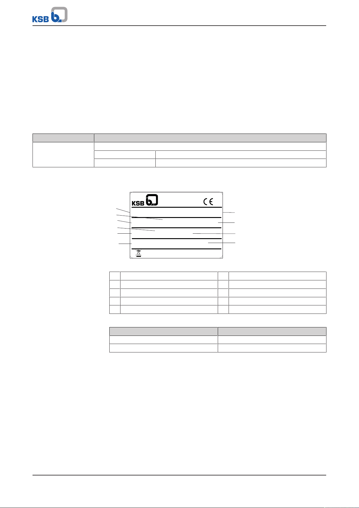
4.3 Name plate
solid particles
Fig.1: Name plate (example)
1 Type series 6 Maximum head
2 Rated current 7 Serial number
3 Rated voltage 8 Total weight
4 Rated power 9 Enclosure
5 Frequency 10 Maximum flow rate
Table5: Key to the serial number
Code Description
2018 Calendar year
09 Calendar week
14 of 64
Hya-Rain/Hya-Rain N
Page 15

4 Description
4.4 Design details
Design
▪ Angled tank designed for wall mounting
▪ Mains water storage tank to EN1717
– Material: PE-LLD, dark
– Storage volume approx. 13l
▪ Float valve for mains water supply (approx. 2.7m³/h)
▪ IP42 enclosure
Pump set
▪ 230V ± 10 %
▪ DOL starting
▪ Thermal class F
▪ Enclosure IP44
▪ Thermal motor protection with automatic reset and start-up
Bearings:
▪ Grease-packed deep groove ball bearings sealed for life
Electrical connection
▪ 230V, 50Hz, 800W
▪ Power input in stand-by mode: 2.5 - 3Watt
▪ 1.5m power cable with shockproof plug
Hya-Rain/Hya-Rain N
15 of 64
Page 16
4 Description
1
2
3
4
5
6
7
8
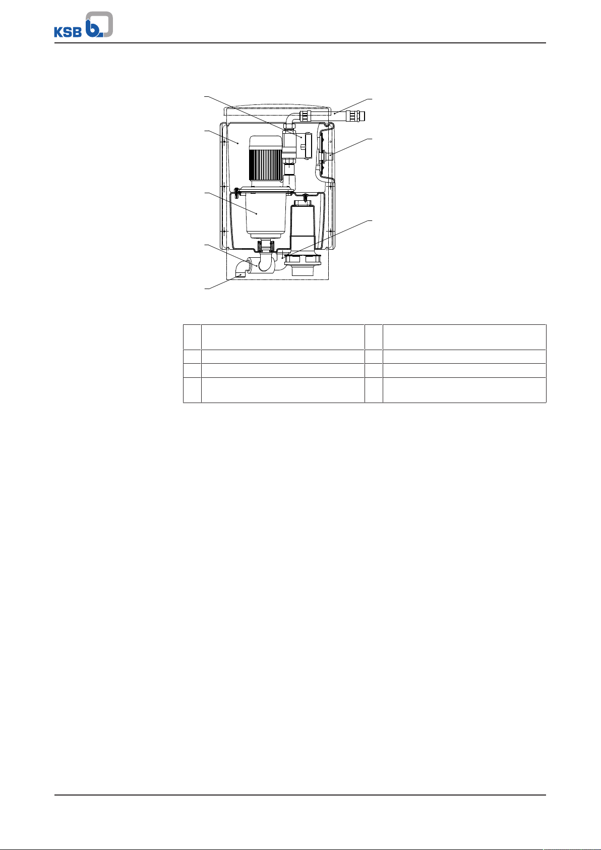
4.5 Configuration and function
Fig.2: Sectional drawing
1 Pump control unit 5 Suction nozzle, rainwater storage
tank
2 Angled tank 6 Discharge outlet
3 High-pressure pump 7 Mains water supply
4 Thee-way valve 8 Suction nozzle, mains water storage
tank
Design A multi-stage self-priming high-pressure pump (3) is installed in an angled tank (2)
designed for wall mounting. Via a three-way valve (4) the high-pressure pump is
connected to a suction nozzle (5) leading out of the system for connection to a
rainwater storage tank.
Function The high-pressure pump (3) withdraws fluid handled from the rainwater storage tank
via the suction nozzle (5). A second suction nozzle (8) leads to an integrated mains
water storage tank, which contains approximately 13l of water. The water in the
mains water storage tank is automatically replenished with drinking water and/or
service water via a float valve. If the sensor fitted in the rainwater storage tank
indicates that the rainwater storage tank is empty, the system will automatically
switch to the mains water storage tank via a three-way valve (4). It will withdraw
water from the mains water storage tank until the rainwater storage tank contains a
sufficient amount of water again. Once the rainwater storage tank contains enough
water again, this condition is signalled to the system, which will then automatically
switch back to withdrawing water from the rainwater storage tank. The pump set is
started and stopped when a consumer installation is opened and closed.
Monitoring equipment For monitoring purposes and for protecting the pump against dry running, the
system is equipped with a pump control unit in the discharge line. When the pressure
falls below approx. 2.5bar (factory setting) the pump control unit starts up the pump
set. When the consumer installation is closed again, the pump control unit stops the
pump set after an after-run time of approx. 10seconds. A lift check valve prevents
the fluid handled from flowing back. The pressure is indicated by a fitted pressure
gauge.
16 of 64
Hya-Rain/Hya-Rain N
Page 17
4 Description
4.6 Noise characteristics
Depending on the operating data of the system, the noise level will be approximately
49-50dB(A).
4.7 Scope of supply
▪ Rainwater harvesting system
– Pump set
– Cervomatic ME control unit and monitoring unit
– Mains water storage tank to EN1717
– Terminals for connecting a booster pump
– Three-way valve with actuator, for automatic switching between rainwater
storage tank and mains water storage tank
– Set of mounting elements for wall mounting (bolts, plug fixings and
mounting brackets)
– Flexible expansion joints for the discharge side as well as for connection to
the mains water supply, length approx. 30/50cm
▪ Bolt hole pattern
▪ Installation/operating manual
Hya-Rain:
▪ Float switch, cable length 20m
Hya-Rain N:
▪ Sensor, cable length 3m, including connection box
4.8 Dimensions and weights
For dimensions refer to the outline drawings. (ðSection10.3.1,Page56)
Table6: Weights
Type series Weight
Without water fill With water fill
[kg] [kg]
Hya-Rain Approx. 26 Approx. 42
Hya-Rain N Approx. 27 Approx. 43
Hya-Rain/Hya-Rain N
17 of 64
Page 18
5 Installation at Site
5 Installation at Site
5.1 Safety regulations
DANGER
Unsuitable electrical installation
Danger to life!
▷ Make sure the electrical installation meets the VDE 0100 installation rules (i.e.
sockets with earthing terminals).
▷ Make sure the electric mains is equipped with a residual current device of
maximum 30 mA.
▷ Always have the electrical connections installed by a trained and qualified
electrician.
5.2 Checks to be carried out prior to installation
Before beginning with the installation check the following:
▪ The system can be operated on the power supply network according to the data
on the name plate. (ðSection4.3,Page14)
▪ The fluid to be handled matches the description of suitable fluids.
(ðSection6.2.3.1,Page30)
▪ The installation room is dry, frost-free and well-ventilated.
▪ The ambient conditions have been met. (ðSection6.2.1,Page30)
▪ The wall (e.g. outside wall) is suitable for accommodating 4plug fixings of
10mm diameter and for carrying the weight of the system.
(ðSection4.8,Page17)
5.3 Setting up and installing the system
ü A suitable installation site has been selected that meets the requirements.
ü Sufficient clearance in all directions is provided for servicing work.
1. Fasten the bolt hole pattern provided to the corresponding wall.
(ðSection10.4,Page57)
2. Drill four holes of 10mm diameter in accordance with the bolt hole pattern.
3. Insert the plug fixings.
4. Mount and align the lower hanging brackets.
5. Undo the nuts. Remove the cover.
6. Place the system on the lower hanging brackets.
7. Fit the upper hanging brackets.
8. Fit the system cover. Fasten it with nuts.
18 of 64
Hya-Rain/Hya-Rain N
Page 19

5 Installation at Site
741.02
5.4 Connecting the piping
5.4.1 Connecting the mains water inlet
CAUTION
Excessive bend of connection line
System defect due to impermissible loads on the system!
Reduced service life!
▷ Connect the connection line without transmitting any stresses or strains.
No forces must act on the connection nozzles and the system.
CAUTION
Pressure higher than mains water back-up limit of 4 bar
System defect due to impermissible load!
▷ Install pressure reducers upstream of the system to make sure that the inlet
pressure of the mains water supply does not exceed 4 bar.
CAUTION
Solid substances in the drinking water (stones, sediments, limescale deposits)
System defect due to impermissible loads!
Reduced service life!
▷ If used in areas where the drinking water quality is affected by the above,
provide a drinking water filter.
NOTE
Fitting a shut-off valve at the site is recommended.
Fig.3: Connecting the mains water inlet
1. Connect the mains water inlet to the mains water supply (float valve 741.02)
R 3/4.
2. Open the mains water supply line.
ð The mains water storage tank will fill automatically once the mains water
supply line is opened.
Hya-Rain/Hya-Rain N
19 of 64
Page 20
5 Installation at Site
5.4.2 Connecting the inlet line
NOTE
The suction-side inlet line (suction hose or suction pipe) must be tightly sealed to
enable self-priming of the pump set.
Fig.4: Connecting the inlet line
ü The inlet line (suction hose or suction pipe) has a diameter of at least 1inch.
1. Lay the inlet line coming from the rainwater storage tank with a continuously
rising slope towards the pump set.
2. Screw the inlet line to the suction nozzle at the bottom of the rainwater
harvesting system.
3. Fit a lift check valve at the rainwater storage tank end of the suction line.
5.4.3 Connecting the discharge line
CAUTION
Excessive bend of connection line
System defect due to impermissible loads on the system!
Reduced service life!
▷ Connect the connection line without transmitting any stresses or strains.
No forces must act on the connection nozzles and the system.
NOTE
Fitting a shut-off valve at the site is recommended.
1. Connect hose 719.02, leading it out at the right or left of the rainwater piping
system. Prevent excessive bending of the flexible connection lines.
20 of 64
Hya-Rain/Hya-Rain N
Page 21

5 Installation at Site
A
Fig.5: Connecting the discharge line
5.4.4 Connecting the overflow
NOTE
For permanent connection to the sewage system we recommend the use of a
siphon trap to prevent bad odours.
EN1717 stipulates that for a tank with air gap design an overflow must be provided.
The overflow has a nominal diameter of 70mm. In the event of leakage of the mains
water back-up system, the fluid handled will be discharged via the overflow as soon
as it rises above the maximum fluid level. Operation without backflow protection
from the sewage system is impermissible; such operation voids the DVGW approval
and the warranty.
If no overflow is fitted in the system, the siphon trap available as accessory must be
connected to the sewage system. The siphon trap is not permanently fastened to the
system. Install it as per DIN1986-100, EN1717.
If no drain line is installed, the overflow can be discharged into an open tank fitted
with a water level indicator.
In this case, adequate monitoring by the user/operator is required.
Fig.6: Connecting the overflow (example of a connection)
A Overflow
Hya-Rain/Hya-Rain N
21 of 64
Page 22

5 Installation at Site
≤ 10 cm
≈ 20 cm
≤ 10 cm
5.5 Electrical connection
DANGER
Electrical connection work by unqualified personnel
Risk of fatal injury due to electric shock!
▷ Always have the electrical connections installed by a trained and qualified
electrician.
▷ Observe regulations IEC 60364 and, for explosion-proof models, EN60079.
WARNING
Incorrect connection to the mains
Damage to the mains network, short circuit!
▷ Observe the technical specifications of the local energy supply companies.
NOTE
A motor protection device is recommended.
5.5.1 Connecting the float switch
Fig.7: Switching points to be observed when fitting the float switch
1. Fasten the float switch to the conduit, e.g. with cable ties or hose clamps,
observing the switching points.
2. Route the power cable of the float switch to the system through the conduit.
3. Undo the nuts at the terminal box.
22 of 64
Hya-Rain/Hya-Rain N
Page 23

5 Installation at Site
Fig.8: Undoing the nuts at the terminal box
4. Remove the terminal box from the system and open it.
Fig.9: Removing the terminal box from the system and opening it
5. Feed the power cable of the float switch through the cable gland provided.
Make sure the cable gland is pointing down. Fasten it in this position.
Fig.10: Connecting the power cable in the terminal box
6. Tighten the cable gland.
7. Connect the power cable.
8. Close the terminal box.
9. Mount the terminal box on the system.
Hya-Rain/Hya-Rain N
23 of 64
Page 24

5 Installation at Site
Overflow
K
S
K
S
K
S
K
S
min.
10 cm
SENSOR terminals
CABLE terminal
Data cable
Data cable connection
reverse polarity protected
SENSOR terminal
Connect sensor at terminal S.
The cables
must not be twisted.
To tighten the cable
the suspended sensor can end
just above the tank floor.
10 cm
PG2
PG3
PG1
Connect the cable
at terminal K.
100%
reference value
Mark the
sensors at
this point.
5.5.2 Connecting the level control system
5.5.2.1 Connecting the sensor
CAUTION
Liquids entering the terminal box
Damage to the sensors!
System defect!
▷ Mount the terminal box approx. 10cm above the rainwater storage tank
overflow.
24 of 64
Fig.11: Connecting the sensor
1. Mount the terminal box supplied at least 10cm above the overflow. Fasten it to
the rainwater storage tank wall or to a pipe.
ð The sensors hang down straight and can move freely.
2. Cut the sensors, so the weights hang approx. 10cm above the floor of the
rainwater storage tank.
3. Strip the ends of the power cables. Connect the cables to terminals K and S.
4. Tighten the cable glands.
Hya-Rain/Hya-Rain N
Page 25

5 Installation at Site
5.5.2.2 Connecting the power cable
Level control and level measurement are effected by a capacitive system. The sensor
delivered is supplied with a voltage of 12V by means of the optional connection
cable; this voltage is not hazardous to humans. A 2-wire rubber-sheathed cable of
1mm2 to 1.5mm2 is appropriate as connection cable. Already routed float switch
power cables of up to max. 50m length can be used for retrofitting.
1. Undo the nuts at the terminal box.
Fig.12: Undoing the nuts at the terminal box
2. Remove the terminal box from the system and open it.
Fig.13: Removing the terminal box from the system and opening it
3. Feed the stripped end of the power cable through the cable gland provided.
Make sure the cable gland is pointing down. Fasten it in this position.
Fig.14: Connecting the cable in the terminal box
4. Tighten the cable gland.
5. Close the terminal box.
6. Mount the terminal box on the system.
5.5.3 Connecting a booster pump (optional)
A booster pump can be connected if the suction lift or suction losses are larger than
7mWC or the suction line has not been laid with a continuously rising slope. The
booster pump exclusively runs in rainwater mode and only when the pump set of the
Hya-Rain/Hya-Rain N
25 of 64
Page 26

5 Installation at Site
system is running. Its power cable is to be connected to L, N and PE in the same
terminal box as the float switch or level control system. Observe the maximum total
rated power of 800W/ 230V.
ü The operating manual of the booster pump used is on hand.
1. Undo the nuts at the terminal box.
Fig.15: Undoing the nuts at the terminal box
2. Remove the terminal box from the system and open it.
Fig.16: Removing the terminal box from the system and opening it
3. Feed the booster pump connection cable through the provided cable gland.
Make sure the cable gland is pointing down. Fasten it in this position.
Fig.17: Connecting the power cable in the terminal box
4. Tighten the cable gland.
5. Close the terminal box.
6. Mount the terminal box on the system.
7. Install the booster pump as described in the manufacturer's operating manual.
26 of 64
Hya-Rain/Hya-Rain N
Page 27

5 Installation at Site
≈ 40 cm
≤ 10 cm
≤ 10 cm
Fig.18: Installation example for a booster pump
5.5.4 Connecting the system
1. Check the available mains voltage against the data on the name plate.
2. Plug the system into the mains.
Hya-Rain/Hya-Rain N
27 of 64
Page 28

6 Commissioning/Start-up/Shutdown
6 Commissioning/Start-up/Shutdown
6.1 Commissioning/Start-up
6.1.1 Prerequisites for commissioning/start-up
Before commissioning/start-up of the system make sure that the following
requirements are met:
▪ The system has been properly connected to the electric power supply and is
equipped with all protection devices.
▪ All relevant VDE standards and/or regulations applicable in the country of use are
complied with.
6.1.2 Priming and venting the system
Filling
ü Connect the mains water back-up system to the mains water supply.
(ðSection5.4.1,Page19)
ü The system has been properly connected to the power supply.
(ðSection5.5,Page22)
1. Set the operating mode selector switch to mains water mode for approximately
15seconds. (ðSection7,Page32)
ð The mains water storage tank will fill automatically.
Venting
ü The mains water storage tank has been filled.
ü The power plug has been plugged into the socket.
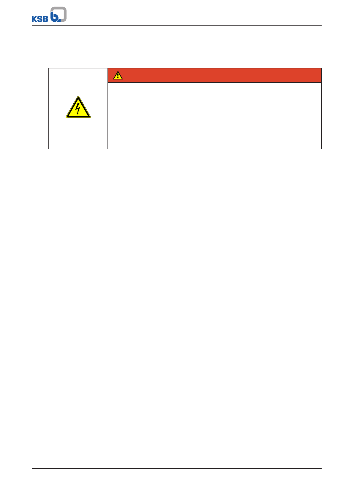
1. Insert the vent hose into the mains water storage tank.
Fig.19: Inserting the vent hose into the mains water storage tank
2. Open a consumer installation.
3. Set the master switch to 1. (ðSection7,Page32)
ð The system will be vented automatically.
4. Close the vent valve.
28 of 64
Hya-Rain/Hya-Rain N
Page 29

6 Commissioning/Start-up/Shutdown
6.1.3 Start-up
Hya-Rain ü The power plug has been plugged into the socket.
1. Set the master switch to 1. (ðSection7,Page32)
ð The pump control unit controls the system automatically:
▪ When a consumer installation is opened, the pump set starts up.
▪ When all consumer installations are closed, the pump set stops.
Table7: Description of indicator lamps
Lamp Description
Green Ready for operation
Red Lack of water: Dry running protection stops the pump set.
Fault: A fault can be reset by pressing the reset key. When the reset key
is pressed and held down, the system is in manual mode.
Hya-Rain N ü The power plug has been plugged into the socket.
1. Set the master switch to 1. (ðSection7,Page32)
2. Calibrate the level display. (ðSection7.3.1,Page36)
6.1.4 Functional test
Dry running protection
ü The system has been properly set up, installed, connected and commissioned.
1. Close the suction-side inlet of the rainwater storage tank.
ð No flow. The pump control unit stops the pump set after an after-run time of
approx. 10seconds.
2. If necessary, repeat the after-run time by pressing the reset key.
Operating modes
ü The system has been properly set up, installed, connected and commissioned.
1. Check the indicator lamps:
Table8: Indicator lamps for operating modes
Operating mode Symbol Indicator lamp
Automatic mode This indicator lamp lights up when the pump automatically switches to the
available water tank.
Mains water mode This indicator lamp lights up when the pump withdraws water from the
mains water storage tank and the mains water back-up system is activated.
Rainwater storage tank This indicator lamp lights up when the pump withdraws water from the
rainwater storage tank.
Hya-Rain/Hya-Rain N
29 of 64
Page 30

6 Commissioning/Start-up/Shutdown
6.2 Operating limits
6.2.1 Ambient conditions
Observe the following parameters and values during operation:
Table9: Permissible ambient conditions
Ambient condition Value
Ambient temperature +40°C maximum
Atmospheric humidity 50% maximum at 40°C
6.2.2 Maximum operating pressure
CAUTION
Permissible operating pressure exceeded
Damage to connections and seals!
▷ Never exceed the operating pressure specified in the data sheet.
The maximum operating pressure is 6 bar.
6.2.3 Fluid handled
6.2.3.1 Permissible fluids to be handled
▪ Service water
▪ Rainwater (not containing abrasive substances)
6.2.3.2 Fluid temperature
Maximum fluid temperature: 35°C
30 of 64
Hya-Rain/Hya-Rain N
Page 31

6 Commissioning/Start-up/Shutdown
6.3 Shutdown/storage/preservation
6.3.1 Measures to be taken for shutdown
WARNING
Unintentional start-up of the rainwater harvesting system
Risk of injury by moving parts!
▷ Only carry out work on the rainwater harvesting system after checking that the
system has been disconnected from the power supply.
▷ Secure the rainwater harvesting system against unintentional starting.
NOTE
To drain the mains water storage tank disconnect the suction line from the system
and set the three-way valve to the middle position.
1. Disconnect the system from the power supply and protect it against inadvertent
start-up.
2. Remove the system as per operating instructions.
3. Shut off the mains water supply and the discharge line.
4. Flush the system as per operating instructions.
5. Leave the system to dry.
6.3.2 Stopping the system
1. Close any valves fitted in the inlet line.
2. Set the master switch to 0.
Hya-Rain/Hya-Rain N
31 of 64
Page 32

7 Operation
3.1
3.2
3.3
1
1.1
1.2
1.3
2
2.2
2.3
3
4
5
2.1
7 Operation
CAUTION
Incorrect operation
Damage to the pump system!
▷ Make sure to comply with all local regulations, particularly the EC Machinery
Directive and the EC Directive on Low-Voltage Equipment.
▷ Check all electric cables prior to commissioning/start-up.
7.1 Control panel
Fig.20: Control panel
1 Operating mode selector switch with operating mode indicator
1.1 Automatic mode
1.2 Mains water mode (manual mode)
1.3 Rainwater mode (manual mode)
2 Level control system (Hya-Rain N only)
2.1 Display
2.2 Percentage setting key
2.3 Timer key
3 Pump control unit
3.1 Lamp (green)
3.2 Lamp (red)
3.3 Reset key
4 Master switch
5 Pressure gauge
32 of 64
Hya-Rain/Hya-Rain N
Page 33

7 Operation
7.2 Mode of operation
7.2.1 Automatic mode
Symbol:
▪ The pump set withdraws the fluid handled from the rainwater storage tank and
pumps it into the consumer system. It is controlled by the pump control unit.
– The rainwater mode lamp is lit in the operating mode indicator.
▪ The pump set is in operation as long as consumer installations (e.g. toilet flush
box, washing machines, garden watering systems) are open. When the consumer
installations are closed, the pump set will continue to run for approx. 10seconds
and will then automatically stop.
▪ When the rainwater storage tank is empty, the pump control unit switches to
mains water mode. As long as the pump set is running, mains water will be
supplied via the float valve. The quantity of mains water supplied will not exceed
current actual requirements. The mains water flow rate depends on the inlet
pressure of the public water supply system.
– The mains water mode lamp is lit in the operating mode indicator.
▪ The system will return to rainwater mode as soon as the water level in the
rainwater storage tank has risen back up to the minimum level.
7.2.2 Mains water mode (manual mode)
Symbol:
▪ The system exclusively withdraws mains water, even if the rainwater storage tank
is filled.
– The mains water mode lamp is lit in the operating mode indicator.
▪ For replacing the mains water in the mains water storage tank or when the
rainwater storage tank requires some maintenance.
7.2.3 Rainwater mode (manual mode)
Symbol:
▪ The system exclusively withdraws rainwater until the rainwater storage tank is
empty.
– The rainwater mode lamp is lit in the operating mode indicator.
▪ The dry running protection may trip the pump set.
– This mode can be used to pump the rainwater storage tank dry.
Hya-Rain/Hya-Rain N
33 of 64
Page 34

7 Operation
7.2.4 Priming
Before withdrawing water from the rainwater storage tank for the first time, the
mains water storage tank must be filled with water. It is filled automatically when
the operating mode selector switch is set to mains water mode for approx.
15seconds and the power plug is connected to a 230V power supply network.
Take the following measures to start the priming process (the process can take up to
4minutes):
ü The mains water storage tank has been filled with water.
1. Open a consumer installation (e.g. water connection in the garden).
2. Set the master switch to 1.
3. Set the operating mode selector switch to rainwater mode.
4. Press and hold down the reset key until the pump set is operating normally.
ð The pressure gauge indicates 2.5 to 4bar.
Should the priming process take longer, verify the following preconditions:
▪ The suction losses correspond to the system specifications.
▪ The suction line is tightly sealed.
▪ The suction line is sufficiently submerged in water.
34 of 64
Hya-Rain/Hya-Rain N
Page 35

7 Operation
1
2
3
7.3 Level control system (Hya-Rain N only)
Fig.21: Level control system
1 Percentage setting key 3 Display
2 Timer key
Table10: Key functions
Key Function
Percentage setting key ▪ Calibrate the fill level.
▪ Set the rainwater storage tank design.
▪ Change values in the menu. (Press down and hold the
key to change a value faster.)
▪ Close the menu.
Timer key ▪ Open the menu.
▪ Go to the next function.
▪ Enable replacement of the water in the rainwater
storage tank.
▪ Display the remaining days until the next module
flushing process.
▪ Display the remaining pump runtime during the
flushing process.
Table11: Level control system display
Display Description
8.8.8 Fill level of the rainwater storage tank and days remaining until the next
rainwater storage tank water replacement
tF Selection of the rainwater storage tank design
75 Fill level in the rainwater storage tank in % (here 75%)
L.. Switching level of the rainwater storage tank (levelxx)
t.. Days remaining until the next rainwater storage tank water replacement
P_ Time of pump operation remaining during rainwater storage tank water
replacement, in minutes
U.. Days until the next automatic valve switchover (protection against
incrustation)
Ei Additional display in the menu and calibration
Err Input signal error (sensor). No fill level can be detected.
Hya-Rain/Hya-Rain N
35 of 64
Page 36

7 Operation
7.3.1 Calibrating the level control system/ setting the rainwater storage tank design
For commissioning of the rainwater harvesting system and replacing the water in the
rainwater storage tank the level control system has to be calibrated and the
rainwater storage tank design has to be set. The level control system has to be
properly installed. (ðSection5.5.2,Page24)
The measured fill level of the rainwater storage tank does not always correspond to
the fill quantity; it depends on the rainwater storage tank design. One of three
rainwater storage tank designs can be selected in the level control system. The level
control system then automatically computes the fill quantity and displays it in%. The
sensor is analysed in steps of 1% with a digital control’s capacitive resistance.
▪ The length of the sensor submerged in the fluid handled is calibrated as 100%.
▪ When the water level drops from 100% to 5%, the system automatically
switches to mains water mode.
▪ When the water level rises again to a level exceeding 7%, the system
automatically switches to rainwater mode.
Table12: Fill level depending on the rainwater storage tank design
Display Rainwater storage tank
Fill level
design
tF1 Cylinder, vertical The fill level corresponds to the fill
quantity.
tF2 Cylinder, horizontal The fill level is computed.
tF3 Round tank The fill level is computed.
Factory setting:
▪ Rainwater storage tank design = tF1
Table13: Calibrating the level display and setting the rainwater storage tank design
Step 1: Calibrate the level display.
ü The level control system has been properly installed.
(ðSection5.5.2,Page24)
1. Press down and hold the percentage setting key for 10seconds
until Ei (calibration) is displayed.
Step 2: Setting the fill level as the reference value
1. Release the percentage setting key.
ð The fill level value calculated is permanently saved as the
reference value for 100%.
ð The display shows tF (rainwater storage tank design selection).
Step 3: Setting the rainwater storage tank design
ü The fill level value has been set.
ü tF (rainwater storage tank design selection) flashes on the displays.
1. Press the percentage setting key.
ð Every time the percentage setting key is pressed, the display
moves to the next rainwater storage tank design (tF1, tF2, tF3).
Step 4: Closing the rainwater storage tank design selection
1. To end the selection press the timer key 4×.
ð If none of the keys are pressed for 20seconds, the menu
automatically closes.
2. For setting the next function (ðSection7.3.2,Page37) press the
timer key again.
36 of 64
Hya-Rain/Hya-Rain N
Page 37

7 Operation
7.3.2 Setting the switching level for the rainwater storage tank
The switching level can be set to between 5 and 90%.
When the water level (switching level) in the rainwater storage tank drops below the
lower setpoint of 5%, the control system switches the three-way valve to mains
water mode.
When the water level exceeds the lower setpoint of 5% by 2%, the control system
switches the three-way valve back to rainwater mode..
To prevent frequent switching of the control system, the minimum difference
(hysteresis) of the switching level (mains water storage tank and rainwater storage
tank) always equals 2%.
Factory setting:
▪ Switching level= 5%
Table14: Setting the switching level for the rainwater storage tank
Step 1: Opening the menu
1. Press down and hold the timer key for 3seconds.
ð The menu opens.
Step 2: Choosing the function
1. Press down and hold the timer key until L.. (switching level of the
rainwater storage tank) is displayed.
Step 3: Setting the switching level
1. Press down and hold the percentage setting key to set the
required setpoint in increments of 1% in the range of 5 to 90%.
2. Press down and hold the timer key to save the required setpoint.
Step 3: Setting the next function or closing the menu
When the setting is completed, the menu automatically shows the next
function.
1. Set the next function (ðSection7.3.3,Page38) or close the
menu by briefly pressing the percentage setting key.
ð If none of the keys are pressed for 10seconds, the menu
automatically closes.
Hya-Rain/Hya-Rain N
37 of 64
Page 38

7 Operation
7.3.3 Setting and displaying the rainwater storage tank water replacement
Rainwater storage tank water replacement serves to flush the rainwater storage
tank. It is only enabled when the operating mode has been set to rainwater mode.
The control unit switches to mains water mode after a set interval. Rainwater storage
tank water replacement ends automatically when the pre-set pump runtime has
passed. When the flushing cycle stops, the control unit resets the interval time to the
pre-set value and switches to rainwater mode.
The interval can be set to between 10 and 60days. The pump runtime can be set to
between 1 and 9minutes.
Factory setting:
▪ Interval = 30days
▪ Pump runtime = 3minutes
Table15: Setting the rainwater storage tank water replacement
Step 1: Opening the menu
1. Press down and hold the timer key for 3seconds.
ð The menu opens.
Alternative:
1. After setting some other functions, press the timer key repeatedly
until t.. (days remaining until the next rainwater storage tank
water replacement) is displayed.
Step 2: Choosing the function
1. Press the timer key repeatedly until t.. (days remaining until the
next rainwater storage tank water replacement) is displayed.
Step 3: Setting the interval for rainwater storage tank water
replacement
1. Press the percentage setting key and set the number of days (10 to
60 days) for the flushing interval.
2. Press down and hold the timer key to save the required setpoint.
ð The display shows P_ (pump runtime remaining during
rainwater storage tank water replacement).
Step 4: Setting the pump runtime
ü The interval for tank water replacement has been set.
ü The display shows P_ (pump runtime remaining during rainwater
storage tank water replacement).
1. Press the percentage setting key and set the pump runtime in
minutes (1 to 9minutes).
2. Press down and hold the timer key to save the required setpoint.
Step 5: Setting the next function or closing the menu
When the setting is completed, the menu automatically shows the next
function.
1. Set the next function (ðSection7.3.4,Page39) or close the
menu by briefly pressing the percentage setting key.
ð If none of the keys are pressed for 10seconds, the menu
automatically closes.
38 of 64
Hya-Rain/Hya-Rain N
Page 39

7 Operation
Table16: Displaying the remaining days until the next rainwater storage tank water
replacement
Step 1: Choosing the function
1. Press the timer key.
ð The display shows the days remaining until the next rainwater
storage tank water replacement.
Step 2: Closing the function
▪ If none of the keys are pressed for 10seconds, the display
automatically closes.
7.3.4 Setting the valve switchover
To prevent incrustation of the three-way valve the control unit switches over the
valve for 12seconds after a set interval (forced movement). The valve then
automatically reverts to its previous position. Valve switchover can be set to between
01) and 10days.
Factory setting:
▪ Valve switchover = 2 days
Table17: Setting the valve switchover
Step 1: Opening the menu
1. Press down and hold the timer key for 3seconds.
ð The menu opens.
Alternative:
1. After setting some other functions, press the timer key repeatedly
until U.. (days until next automatic valve switchover) is displayed.
Step 2: Choosing the function
1. Press the timer key repeatedly until U.. (days until next automatic
valve switchover) is displayed.
Step 3: Setting the days until the next automatic valve switchover
1. Press the percentage setting key and set the number of days (1 to
9 days) for the flushing interval.
2. Press down and hold the timer key to save the required setpoint.
ð The menu is closed automatically.
1) 0 = function off
Hya-Rain/Hya-Rain N
39 of 64
Page 40

8 Servicing/Maintenance
8 Servicing/Maintenance
8.1 General information/safety regulations
DANGER
Unintentional start-up of the rainwater harvesting system
Danger to life from live parts!
▷ Always disconnect the rainwater harvesting system from the power supply
before repair or maintenance work is carried out.
▷ Disconnect the plug from the electric mains.
▷ Secure the system against unintentional starting.
WARNING
Unintentional start-up of the rainwater harvesting system
Risk of injury by moving parts!
▷ Only carry out work on the rainwater harvesting system after checking that the
system has been disconnected from the power supply.
▷ Secure the rainwater harvesting system against unintentional starting.
WARNING
Work on the rainwater harvesting system by unqualified personnel
Risk of personal injury!
▷ Always have repair and maintenance work performed by specially trained,
qualified personnel.
WARNING
Insufficient stability
Risk of crushing hands and feet!
▷ During assembly/dismantling, secure the pump (set)/pump parts to prevent
tilting or tipping over.
The operator ensures that maintenance, inspection and installation are performed by
authorised, qualified specialist personnel who are thoroughly familiar with the
manual.
Always observe the safety instructions and information.
A regular maintenance schedule will help avoid expensive repairs and contribute to
trouble-free, reliable operation of the rainwater harvesting system with a minimum
of maintenance expenditure and work.
Never use force when dismantling and reassembling the rainwater harvesting system.
NOTE
40 of 64
All maintenance work, service work and installation work can be carried out by KSB
Service or authorised workshops. For contact details please refer to the enclosed
"Addresses" booklet or visit "www.ksb.com/contact" on the Internet.
Hya-Rain/Hya-Rain N
Page 41

8 Servicing/Maintenance
A
8.2 Maintenance/inspection
KSB recommends the following regular servicing schedule:
Table18: Overview of maintenance work
Maintenance interval Maintenance work
Monthly Replace the stored mains water.
Every 6 months Check the mains water mode.
Check the pump control unit.
Check the discharge lines.
Every 8000 operating hours
approximately
8.2.1 Replacing the stored mains water
Hya-Rain We recommend replacing the stored mains water once a month.
1. Set the operating mode selector switch to mains water mode.
(ðSection7.2.2,Page33)
2. Flush the toilet or activate another consumer installation 2 or 3 times.
ð The noise of the mains water flowing into the tank can be heard.
3. Set the operating mode selector switch back to automatic mode.
(ðSection7.2.1,Page33)
Hya-Rain N The stored mains water is replaced automatically.
Replace the rolling element bearings.
8.2.2 Checking the mains water mode
1. Check the overflow for any escaping water.
ð If water escapes, the float valve could be defective and has to be replaced.
Replacing the float valve
Fig.22: Replacing the float valve
1. Shut off the mains water supply.
2. Undo the four screws (A) at the cover on the side.
3. Remove the cover.
4. Pull out the float valve.
5. Fit a new float valve and new sealing elements.
6. Fit the cover.
7. Screw in the four screws (A) hand-tight at the cover on the side.
Hya-Rain/Hya-Rain N
41 of 64
Page 42

8 Servicing/Maintenance
8.2.3 Checking the pump control unit
1. Open a consumer installation and close it again after the water has been
running for a short time.
ð Check that the pump stops approx. 10seconds after all consumer
installations have been closed.
8.2.4 Checking the discharge lines
1. Check the discharge lines/ discharge hoses for any leakage and damage.
ð In the event of visible leakage or severe damage of the metal sheath, replace
the hoses.
8.3 Drainage/cleaning
WARNING
Fluids handled, consumables and supplies which are hot and/or pose a health
hazard
Hazard to persons and the environment!
▷ Collect and properly dispose of flushing fluid and any fluid residues.
▷ Wear safety clothing and a protective mask if required.
▷ Observe all legal regulations on the disposal of fluids posing a health hazard.
1. Flush the system.
8.4 Dismantling the system
DANGER
Work on the rainwater harvesting system by unqualified personnel
Hazard from live parts!
▷ The system must only be dismantled and reassembled by a trained and qualified
electrician.
▷ The system must be de-energised before any work is carried out.
▷ Secure the system against unintentional starting.
8.4.1 Removing the pump set from the piping
1. Set the master switch to 0. (ðSection7,Page32)
2. Pull the power plug out of the socket.
3. Shut off the mains water supply and the discharge line.
4. Separate the suction connection. Set the three-way valve to the middle position.
ð Drain the mains water storage tank.
5. Remove the locking pin of the control unit. Push the control unit upwards and
pull it out.
42 of 64
Hya-Rain/Hya-Rain N
Page 43

8 Servicing/Maintenance
Fig.23: Removing the control panel
6. Undo the fixing stud of the mounting plate.
Fig.24: Removing the mounting plate
7. Pull the plate with pressure gauge and hose out sideways.
Fig.25: Removing the plate
8. For Hya-RainN disconnect the power supply of the display panel.
Fig.26: Disconnecting the power supply of the display panel (Hya-RainN)
9. Undo the nuts. Remove the system cover.
10. Disconnect the discharge line with a suitable tool.
Hya-Rain/Hya-Rain N
43 of 64
Page 44

8 Servicing/Maintenance
Fig.27: Disconnecting the discharge line
11. Undo the screws securing the pump.
Fig.28: Undoing the screws securing the pump
12. Pull out the pump set.
Fig.29: Pulling out the pump set
8.4.2 Removing the pump control unit
1. Remove the cable ties.
2. Undo the union nut at the discharge nozzle.
44 of 64
Hya-Rain/Hya-Rain N
Page 45

8 Servicing/Maintenance
Fig.30: Undoing the union nut at the discharge nozzle
Hya-Rain/Hya-Rain N
45 of 64
Page 46

8 Servicing/Maintenance
8.4.3 Removing the mechanical seal
ü The pump set has been properly removed from the system.
(ðSection8.4.2,Page44)
1. Place the pump set with the motor below in a clean assembly area.
2. Undo the hexagon socket head cap screws at the motor. Remove the suction
casing.
Fig.31: Removing the suction casing from the motor
3. Undo the impeller nut.
Fig.32: Undoing the impeller nut
4. Remove the impeller.
ð The mechanical seal is freely accessible.
Fig.33: Removing the impeller
5. Remove the circlip with a suitable tool.
46 of 64
Hya-Rain/Hya-Rain N
Page 47

8 Servicing/Maintenance
Fig.34: Removing the circlip
6. Pull the mechanical seal off the shaft.
7. Clean the removed components, check them for any wear. Replace them if
necessary.
8.5 Reassembling the system
DANGER
Work on the rainwater harvesting system by unqualified personnel
Hazard from live parts!
▷ The system must only be dismantled and reassembled by a trained and qualified
electrician.
▷ The system must be de-energised before any work is carried out.
▷ Secure the system against unintentional starting.
8.5.1 Installing the mechanical seal
ü The components have been cleaned and checked for any wear. They have been
replaced if necessary.
1. Slide the mechanical seal onto the shaft with a suitable tool. Make sure that the
mechanical seal is not damaged by burrs.
2. Fit the circlip.
Fig.35: Slide the mechanical seal onto the shaft.
3. Slide the impeller onto the shaft.
Hya-Rain/Hya-Rain N
47 of 64
Page 48

8 Servicing/Maintenance
Fig.36: Sliding the impeller onto the shaft
4. Fit the impeller nut and tighten it hand-tight.
Fig.37: Tightening the impeller nut
5. Fit an O-ring flush on the motor.
6. Position the suction casing on the motor. Fasten it with hexagon socket head
cap screws.
8.5.2 Installing the pump control unit
1. Fasten the union nut at the discharge nozzle.
Fig.38: Fastening the union nut at the discharge nozzle
2. Connect the cables.
48 of 64
Hya-Rain/Hya-Rain N
Page 49

8 Servicing/Maintenance
412.01
8.5.3 Installing the pump set
1. Grease O-ring 412.01.
2. Hold the pump set in position. Insert the inlet section into the fitting on the
tank floor.
Fig.39: Holding the pump set in position and inserting the inlet section into the
fitting
3. Tighten the screws securing the pump.
Fig.40: Fitting the screws securing the pump
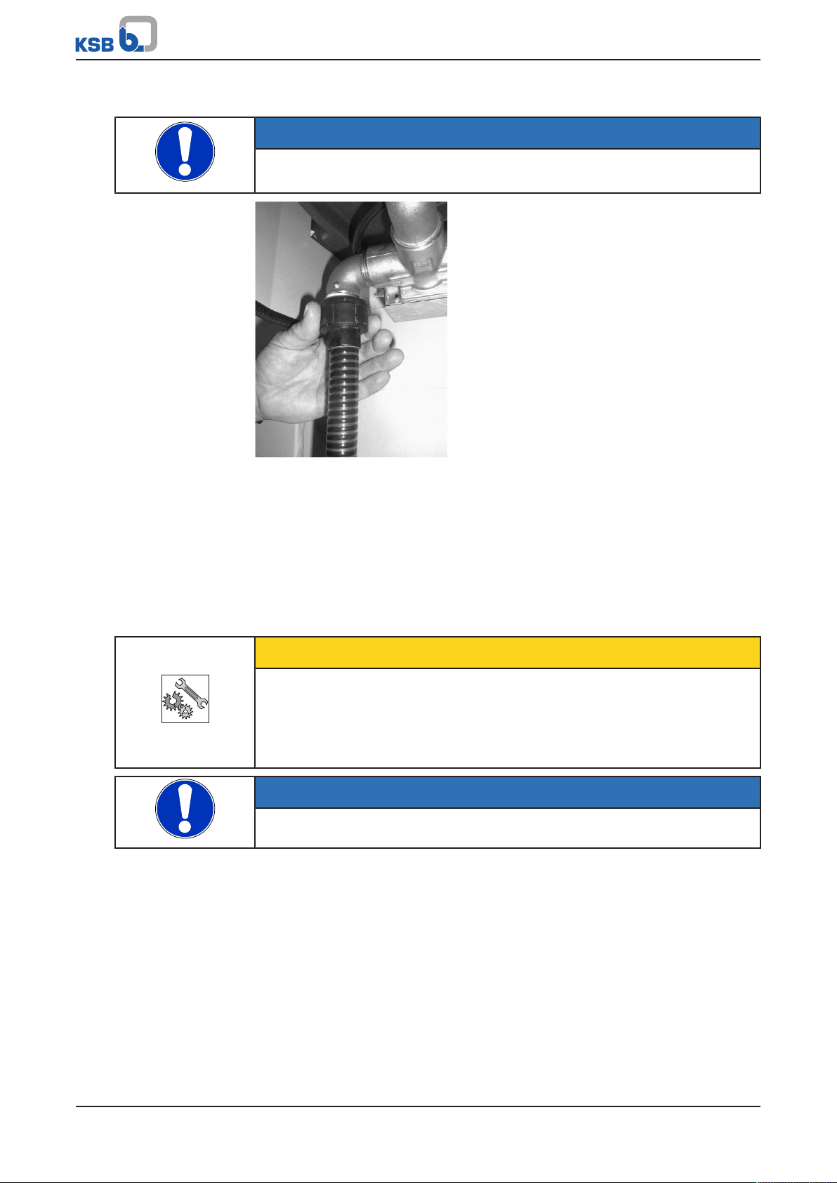
4. Connect hose 719.02, leading it out at the right or left of the rainwater piping
system. Prevent excessive bending of the flexible connection lines.
Fig.41: Connecting the discharge line
5. Fit the system cover. Fasten it with nuts.
6. For Hya-Rain N connect the power cable of the display panel.
Hya-Rain/Hya-Rain N
49 of 64
Page 50

8 Servicing/Maintenance
Fig.42: Connecting the power cable of the display panel (Hya-RainN)
7. Insert the plate with pressure gauge and hose from the side.
Fig.43: Inserting the plate
8. Fit the mounting plate. Tighten the fastening screw hand-tight.
Fig.44: Fitting the mounting plate
9. Insert the control unit. Fasten it with the locking pin.
50 of 64
Fig.45: Inserting the control unit
10. Connect the suction line. Set the three-way valve to the corresponding position.
11. Connect and open the mains water supply and the discharge line.
(ðSection5.4,Page19)
12. Check the available mains voltage against the data on the name plate. Plug the
power plug into the socket.
13. Set the master switch to 1. (ðSection7,Page32)
Hya-Rain/Hya-Rain N
Page 51

9 Trouble-shooting
9 Trouble-shooting
WARNING
Improper work to remedy faults
Risk of injury!
▷ For any work performed to remedy faults, observe the relevant information
given in this instruction manual and/or in the product literature provided by the
accessories manufacturer.
If problems occur that are not described in the following table, consultation with the
KSB customer service is required.
Table19: Trouble-shooting
Fault Possible cause Remedy
Pump is running, but does not
deliver.
Excessive frequency of pump
starts
Pump is running but delivering
insufficient flow rate or
pressure.
Pump stops during operation. ▪ Power failure
Pump stops during operation;
"fault" is indicated.
System does not start. ▪ Pump control unit fault ▪ Press the reset key or interrupt the mains
System does not stop. ▪ Foreign object in pump
Excessive noise level ▪ Pump in contact with
Tank overflowing ▪ Dirt deposits in valve ▪ Remove dirt/limescale deposits in valve;
Err (alarm displayed)
2)
▪ Pump has not been primed.
▪ Excessive suction losses
▪ Leaking suction line ▪ Eliminate leakage
▪ Air pocket in suction line ▪ Fill suction line or lay with rising slope.
▪ Suction strainer clogged ▪ Clean the suction strainer.
▪ Discharge line shut off ▪ Open discharge line.
▪ Leaking consumer
installation
▪ Leaking swing check valve ▪ Fit new swing check valve and/or new
▪ Very low level of
consumption
▪ Minimum flow rate not
achieved
▪ Pump takes in air. ▪ Check suction line.
▪ Suction strainer clogged ▪ Clean the suction strainer.
▪ Undervoltage
▪ Thermal switch tripped
because of overheating
▪ Earth leakage circuit breaker
has tripped.
▪ Air in suction line ▪ Flush the suction line by opening several
control unit
securing screws
▪ Fault at connection or sensor ▪ Check control cable in the rainwater
▪ Prime the pump.
▪ Reduce suction head.
▪ Choose larger cross sections.
▪ Eliminate leakage in consumer installation.
pump control unit.
▪ Increase toilet flush volume, clean strainer
in toilet cistern if necessary.
▪ Check power supply.
▪ Check pump for smooth operation.
▪ Have the insulation resistance checked by a
trained electrician.
consumer installations and pressing the
reset key for approx. 3 to 5minutes.
voltage.
▪ Clean the pump control unit; replace it if
necessary.
▪ Align the pump manually ensuring that it
does not come into contact with the
screws.
replace float switch if necessary.
storage tank.
▪ Replace sensor.
2) For Hya-RainN only
Hya-Rain/Hya-Rain N
51 of 64
Page 52

Increasing the suction line
diameter
Setting of the pressure
reducer
Eliminating pressure surges
by throttling the flow
Membrane-type
accumulator
9 Trouble-shooting
How to avoid pressure surges
DIN1988, Part3, stipulates that for withdrawal rates >0.5l/s an inside pipe diameter
of at least 20mm must be selected.
Pressure surges occur whenever the pressure differences exceed 2bar. If the pressure
gauge indicates a pressure of 5bar with the valve closed, and this pressure drops to
2.5bar when the valve is opened, the pressure applied when the valve is closed must
be reduced by at least 1bar.
If an isolating valve or a pressure reducer is fitted in the mains water supply line
upstream of the system, the valve/reducer must be throttled until the pressure surge
is eliminated. The drawback of this method is the low mains water back-up flow rate.
It must be checked if the mains water back-up flow rate is sufficient to meet standard
consumption requirements. The lack-of-water monitoring equipment must not trip in
mains water mode when the max. quantity of water that can be withdrawn is
withdrawn. If the lack-of-water monitoring equipment trips, the discharge-side flow
rate must be throttled.
Fit an 8-litre membrane-type accumulator in the pipe upstream of the system inlet.
Such an accumulator will attenuate extreme pressure drops in small-diameter pipes
and absorb surges without throttling the flow rate.
52 of 64
Hya-Rain/Hya-Rain N
Page 53

10 Related Documents
81-99
741.02
591
655
719.02
719.01
71-14
719.03
X
X
672
81-99.01
82-16
691
691
741.01
741.03
411.01
719.01
10 Related Documents
10.1 General assembly drawing with list of components
Fig.46: Sectional drawing
Table20: List of components
Part No. Description
411.01 Profile seal for the pump control unit
591 Mains water storage tank
62-12 Level sensor for the rainwater storage tank
655 Pump, complete with set of sealing elements
672 Globe valve (vent valve)
691 Pressure gauge
71-14 Pipe with sealing element
719.01 Hose (inlet side)
719.02 Hose (discharge side)
719.03 Hose with clamp
741.01 Three-way valve with tank
741.02 Float valve, complete
741.03 Thee-way valve
81-9 Relay
81-99 Electrical part (complete)
81-99.01 Electrical part (printed circuit board for Hya-RainN)
82-16 Control unit / control panel for Hya-Rain
82-16 Control unit / control panel for Hya-RainN
99-9 Set of sealing elements
3)
3) Pump components, see MultiEco (5180.5) type series booklet.
Hya-Rain/Hya-Rain N
53 of 64
Page 54

10 Related Documents
10.2 Exploded view with list of components (pump)
54 of 64
Fig.47: Exploded view of the pump
Table21: List of components
Part No. Comprising Description
10-5.01/.02 Pump section
106 Suction casing
109 Stage casing without return
vanes
171 Diffuser
230 Impeller
746 Valve disc
270 Deflector
321.01/.02 Radial ball bearing
45-4 Spacer
400.01/.02 Gasket
412.01/.02/.03 O-ring
Hya-Rain/Hya-Rain N
Page 55

10 Related Documents
Part No. Comprising Description
433 Mechanical seal
554.02 Washer
571 Bail
81-22 81-22.01/.02 Terminal box cover
900.01 Bolt/screw
81-42 Terminal box
81-22.01/.03 Terminal box cover
824 Cable
838 Switch
900.01/.02/.03 Bolt/screw
831 831 Fan impeller
832 Fan hood
837 Capacitor
99-20 Repair kit
270 Deflector
321.01/.02 Radial ball bearing
45-4 Spacer
400.01/.02 Gasket
412.01/.02/.03 O-ring
554.02 Mechanical seal
921.01/.02 Shaft nut
931 Lock washer
932.01/.02/.03 Circlip
921 Shaft nut
931 Lock washer
932.01/.02/.03 Circlip
Hya-Rain/Hya-Rain N
55 of 64
Page 56

10 Related Documents
56
28
154
168
360
R1
132
90
410
R1
583
439
630
A
B
C
D
10.3 Dimensions and connections
10.3.1 Hya-Rain / Hya-Rain N
Fig.48: Dimensions [mm]
A Suction side C Discharge side
B Overflow, drain line DN70 D Mains water connection
56 of 64
Hya-Rain/Hya-Rain N
Page 57

10 Related Documents
1
3
2
476
185
10.3.2 Connections
Fig.49: Connections
1 Mains water connection, with air gap inside the tank
2 Mechanical float valve
3 Overflow4) for direct connection of DN70 drain lines to EN12056
10.4 Drilling pattern for wall mounting
Fig.50: Drilling pattern for wall mounting, dimensions [mm]
4) The overflow must be connected via an air gap to EN1717, otherwise the DVGW-approval is void.
Hya-Rain/Hya-Rain N
57 of 64
Page 58

10 Related Documents
A0
H
-S1
1
2
1b
2a1a2b
(119)
L1
N
-Q1
1
2
2a
1a
(118)
1
21a2b
1
2 2a
1a
-K1
2.4
2.4
2.5
2.5
L
N
PE
M
(130)
(135)
GY (128)
OG (129)
BU (126)
BN (125)
GN/YF (127)
(124)
(131)
(123)
(122)
-H1
X1
-H2 -H3
X2
X1
X2
X1
X2
A TW
Z
-Y1
-A1
-K1
2.2
M
~
-M1
LINE (120)
LINE (120)
MOTOR (121)
MOTOR (121)
PE
-A2
BN
(122.1)
(133)
M
~
-M2
-S2
L N
PE
1
2
L
N
PE
(132)
sw
rt
PE
bl
PZ 039
A5
niv.
N
L1
BN (125)
BU
PE
(132.1)
-K1
2.2
TW
PE
BU (126)
10.5 Wiring diagrams
10.5.1 Hya-Rain
Fig.51: Hya-Rain wiring diagram
118 Master switch 130 Plug
119 Operating mode selector switch with operating
131 Pump set
mode indicator
A = automatic
0 = mains water mode (manual mode)
H = rainwater mode (manual mode)
122 Automatic mode 132 Display of the pump control unit
122.1 Float switch 132.1 Pump control unit
123 Mains water mode (manual mode) 133 Booster pump (optional)
124 Rainwater mode (manual mode) 135 Thee-way valve
58 of 64
Hya-Rain/Hya-Rain N
Page 59

10 Related Documents
A0
H
S1
1
2
1b
2a1a 2b
(119)
L1
N
Q1
1 2
2a
1a
(118)
1
2
1a 2b
1 2 2a
1a
K1
2.4
2.4
2.5
2.5
L
N
PE
M
(130)
(135)
GY (128)
OG (129)
BU (126)
BN (125)
GN/YF (127)
(124)
(131)
(123)
(122)
H1
X1
H2 H3
X2
X1
X2
X1
X2
A TW
Z
Y1
A1
K1
2.2
M
~
M1
LINE (120)
LINE (120)
MOTOR (121)
MOTOR (121)
PE
A2
A3
(139)
(133)
M
~
M2
S2
L N
PE
1
2
L
N
PE
(132)
sw
rtPEbl
K1
2.2
rtbl
PZ 039/04
A5
niv.
N
L1
A4
(138)
(139)
N
L1
(132.1)
10.5.2 Hya-Rain N
Fig.52: Hya-RainN wiring diagram
118 Master switch 132 Display of the pump control unit
119 Operating mode selector switch with operating
132.1 Pump control unit
mode indicator
A = automatic
0 = mains water mode (manual mode)
H = rainwater mode (manual mode)
122 Automatic mode 133 Booster pump (optional)
123 Mains water mode (manual mode) 135 Thee-way valve
124 Rainwater mode (manual mode) 138 Level control system / display
130 Plug 139 Sensor
131 Pump set
Hya-Rain/Hya-Rain N
59 of 64
Page 60

10 Related Documents
60 of 64
Hya-Rain/Hya-Rain N
Page 61

11 EU Declaration of Conformity
11 EU Declaration of Conformity
Manufacturer: KSB SE & Co. KGaA
Johann-Klein-Straße 9
67227 Frankenthal (Germany)
The manufacturer herewith declares that the product:
Hya-Rain
Hya-Rain N
Serial number range: 2018w01 to 2019w52
▪ is in conformity with the provisions of the following Directives as amended from time to time:
– Pump set: EC Machinery Directive 2006/42/EC
– Pump set: Electromagnetic Compatibility Directive 2014/30/EU
The manufacturer also declares that
▪ the following harmonised international standards have been applied:
– ISO 12100
– EN 809
▪ Applied national technical standards and specifications, in particular:
– DIN 1988-100,
– EN 1717
Person authorised to compile the technical file:
Armin Reisinger
Technical Project Manager, Product Development, Business Unit Automation and Drives
KSB SE & Co. KGaA
Johann-Klein-Straße 9
67227 Frankenthal (Germany)
The EU Declaration of Conformity was issued in/on:
Frankenthal, 1 February 2018
Joachim Schullerer
Head of Product Development Pump Systems and Drives
KSB SE & Co. KGaA
Johann-Klein-Straße 9
67227 Frankenthal
Hya-Rain/Hya-Rain N
61 of 64
Page 62

12 Certificate of Decontamination
12 Certificate of Decontamination
Type: ................................................................................................................................
Order number/
Order item number5): ................................................................................................................................
Delivery date: ................................................................................................................................
Field of application: ................................................................................................................................
Fluid handled5): ................................................................................................................................
Please tick where applicable5):
Radioactive Explosive Corrosive Toxic
Harmful Bio-hazardous Highly flammable Safe
Reason for return5): ................................................................................................................................
Comments: ................................................................................................................................
................................................................................................................................
The product/accessories have been carefully drained, cleaned and decontaminated inside and outside prior to dispatch/
placing at your disposal.
We herewith declare that this product is free from hazardous chemicals, biological and radioactive substances.
For mag-drive pumps, the inner rotor unit (impeller, casing cover, bearing ring carrier, plain bearing, inner rotor) has been
removed from the pump and cleaned. In cases of containment shroud leakage, the outer rotor, bearing bracket lantern,
leakage barrier and bearing bracket or adapter have also been cleaned.
For canned motor pumps, the rotor and plain bearing have been removed from the pump for cleaning. In cases of leakage at
the stator can, the stator space has been examined for fluid leakage; if fluid handled has penetrated the stator space, it has
been removed.
No special safety precautions are required for further handling.
The following safety precautions are required for flushing fluids, fluid residues and disposal:
...............................................................................................................................................................
...............................................................................................................................................................
We confirm that the above data and information are correct and complete and that dispatch is effected in accordance with the
relevant legal provisions.
.................................................................. ....................................................... .......................................................
Place, date and signature Address Company stamp
5) Required fields
62 of 64
Hya-Rain/Hya-Rain N
Page 63

Index
Index
B
Bearings15
C
Certificate of decontamination62
Commissioning/start-up28
D
Design15
Designation14
Disposal13
E
Event of damage6
F
Faults
Causes and remedies51
Fields of application8
I
Intended use8
K
Key to safety symbols/markings7
M
Misuse8
O
Other applicable documents6
P
Personnel9
Q
Qualification9
R
Rainwater storage tank36
Return to supplier12
S
Safety8
Safety awareness9
Shutdown31
W
Warnings7
Warranty claims6
Hya-Rain/Hya-Rain N
63 of 64
Page 64

KSB SE & Co. KGaA
Johann-Klein-Straße 9 • 67227 Frankenthal (Germany)
Tel. +49 6233 86-0
www.ksb.com
5602.81/14-EN (01442695)
 Loading...