

Page 1
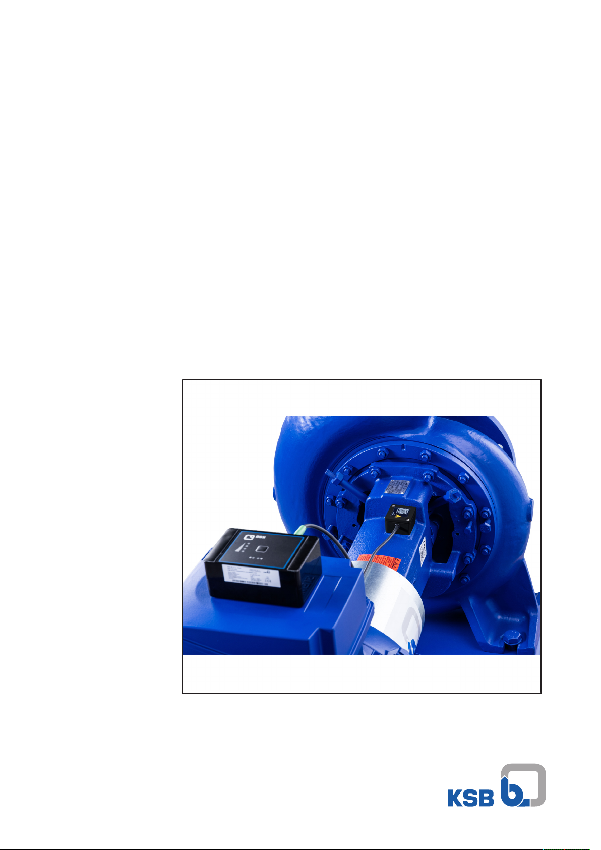
KSB Guard
Installation/Operating Manual
Page 2

Legal information/Copyright
Installation/Operating Manual KSB Guard
Original operating manual
All rights reserved. The contents provided herein must neither be distributed, copied, reproduced,
edited or processed for any other purpose, nor otherwise transmitted, published or made available to a
third party without the manufacturer's express written consent.
Subject to technical modification without prior notice.
© KSB SE & Co. KGaA, Frankenthal 09/11/2018
Page 3

Contents
Contents
1 General.................................................................................................................................................... 5
1.1 Principles ...........................................................................................................................................................5
1.2 Target group.....................................................................................................................................................5
1.3 Other applicable documents............................................................................................................................5
1.4 Symbols .............................................................................................................................................................5
1.5 Key to safety symbols/markings.......................................................................................................................5
2 Safety...................................................................................................................................................... 7
2.1 General..............................................................................................................................................................7
2.2 Intended use .....................................................................................................................................................7
2.3 Personnel qualification and personnel training.............................................................................................7
2.4 Consequences and risks caused by non-compliance with this operating manual........................................7
2.5 Safety awareness ..............................................................................................................................................8
2.6 Software changes .............................................................................................................................................8
3 Transport/Temporary Storage/Disposal............................................................................................... 9
3.1 Checking the condition upon delivery............................................................................................................9
3.2 Transport...........................................................................................................................................................9
3.3 Storage..............................................................................................................................................................9
3.4 Disposal ...........................................................................................................................................................10
4 Description............................................................................................................................................ 11
4.1 General description ........................................................................................................................................11
4.2 Name plates ....................................................................................................................................................11
4.3 Technical data.................................................................................................................................................11
4.4 Function ..........................................................................................................................................................12
4.5 Gateway ..........................................................................................................................................................13
4.6 Sensor unit ......................................................................................................................................................14
4.7 Transmission and battery unit .......................................................................................................................14
5 Installation/Commissioning................................................................................................................. 15
5.1 Installation ......................................................................................................................................................15
5.1.1 Installing the gateway.......................................................................................................................15
5.1.2 Installing the sensor unit...................................................................................................................18
5.1.3 Establishing a connection between the sensor unit and the transmission and battery unit........20
5.1.4 Commissioning...................................................................................................................................20
5.1.5 Installing the transmission and battery unit ....................................................................................21
5.1.6 Routing the connecting cable ...........................................................................................................21
5.2 Commissioning the gateway..........................................................................................................................22
5.3 Assigning and setting up ...............................................................................................................................23
6 Operation.............................................................................................................................................. 25
6.1 Operating modes of transmission and battery unit.....................................................................................25
6.2 Taking manual measurement and displaying signal strength.....................................................................25
6.3 Reading out the transmission status .............................................................................................................25
7 Changing the Batteries........................................................................................................................ 27
8 Dismantling .......................................................................................................................................... 28
8.1 Dismantling the gateway...............................................................................................................................28
8.2 Dismantling the transmission and battery unit............................................................................................28
8.3 Dismantling the sensor unit...........................................................................................................................29
9 Trouble-shooting.................................................................................................................................. 30
9.1 Trouble-shooting the gateway......................................................................................................................30
9.2 Trouble-shooting the transmission and battery unit/ sensor unit...............................................................30
10 Related Documents.............................................................................................................................. 32
10.1 Recommended mounting position for sensor unit ......................................................................................32
KSB Guard
3 of 40
Page 4

Contents
11 EU Declaration of Conformity............................................................................................................. 35
Index ..................................................................................................................................................... 36
4 of 40
KSB Guard
Page 5
1 General
!
DANGER
!
WARNING
CAUTION
1 General
1.1 Principles
This instruction manual is valid for the type series and variants indicated on the front
cover.
The manual describes the proper and safe use of this equipment in all phases of
operation.
The name plate indicates the type series, the main operating data and the serial
number. The serial number uniquely describes the product and is used as
identification in all further business processes.
In the event of damage, immediately contact your nearest KSB Service centre to
maintain the right to claim under warranty.
1.2 Target group
This instruction manual is aimed at the target group of trained and qualified
specialist technical personnel.
1.3 Other applicable documents
Table1: Overview of other applicable documents
Document Contents
Operating manual for pump/
pump set
For accessories and/or integrated machinery components, observe the relevant
manufacturer's product literature.
Description/operation of pump/pump set
1.4 Symbols
Table2: Symbols used in this manual
Symbol Description
✓ Conditions which need to be fulfilled before proceeding with the
step-by-step instructions
⊳ Safety instructions
⇨
⇨ Cross-references
1.
2.
Result of an action
Step-by-step instructions
Note
Recommendations and important information on how to handle
the product
1.5 Key to safety symbols/markings
Table3: Definition of safety symbols/markings
Symbol Description
DANGER
This signal word indicates a high-risk hazard which, if not avoided,
will result in death or serious injury.
WARNING
This signal word indicates a medium-risk hazard which, if not
avoided, could result in death or serious injury.
CAUTION
This signal word indicates a hazard which, if not avoided, could
result in damage to the machine and its functions.
KSB Guard
5 of 40
Page 6
1 General
Symbol Description
General hazard
In conjunction with one of the signal words this symbol indicates a
hazard which will or could result in death or serious injury.
Electrical hazard
In conjunction with one of the signal words this symbol indicates a
hazard involving electrical voltage and identifies information about
protection against electrical voltage.
Machine damage
In conjunction with the signal word CAUTION this symbol indicates
a hazard for the machine and its functions.
6 of 40
KSB Guard
Page 7

2 Safety
!
DANGER
2 Safety
All the information contained in this section refers to hazardous situations.
In addition to the present general safety information the action-related safety
information given in the other sections must be observed.
2.1 General
This instruction manual contains general installation, operating and maintenance
instructions that must be observed to ensure safe operation of the system and
prevent personal injury and damage to property.
The safety information in all sections of this manual must be complied with.
The instruction manual must be read and understood by the responsible specialist
personnel/operators prior to installation and commissioning.
The contents of this instruction manual must be available to the specialist personnel
at the site at all times.
Information attached directly to the product must always be complied with and kept
in a perfectly legible condition at all times. This applies to, for example:
▪ Markings for connections
▪ Name plate
The operator is responsible for ensuring compliance with all local regulations not
taken into account in this instruction manual.
2.2 Intended use
▪ The values specified in the technical product literature for the mains voltage and
ambient temperature must not be exceeded. The device must only be operated
in accordance with the instructions provided in the operating manual and other
applicable documents.
2.3 Personnel qualification and personnel training
All personnel involved must be fully qualified to install, operate, maintain and
inspect the equipment this manual refers to. The responsibilities, competence and
supervision of all personnel involved in transport, installation, operation,
maintenance and inspection must be clearly defined by the operator.
Deficits in knowledge must be rectified by means of training and instruction
provided by sufficiently trained specialist personnel. If required, the operator can
commission the manufacturer/supplier to train the personnel.
Training on the device must always be supervised by specialist technical personnel.
2.4 Consequences and risks caused by non-compliance with this operating manual
▪ Non-compliance with this operating manual will lead to forfeiture of warranty
cover and of any and all rights to claims for damages.
▪ Non-compliance can, for example, have the following consequences:
– Hazards to persons due to electrical, thermal, mechanical and chemical
effects and explosions
– Failure of important product functions
– Failure of prescribed maintenance and servicing practices
KSB Guard
7 of 40
Page 8

2 Safety
2.5 Safety awareness
In addition to the safety information contained in this manual and the intended use,
the following safety regulations shall be complied with:
▪ Accident prevention, health regulations and safety regulations
▪ Safety regulations for handling hazardous substances
▪ Applicable standards, directives and laws
2.6 Software changes
The software has been specially created for this product and thoroughly tested.
It is impermissible to make any changes or additions to the software or parts of the
software.
8 of 40
KSB Guard
Page 9
3 Transport/Temporary Storage/Disposal
3 Transport/Temporary Storage/Disposal
3.1 Checking the condition upon delivery
1. On transfer of goods, check each packaging unit for damage.
2. In the event of in-transit damage, assess the exact damage, document it and
notify KSB or the supplying dealer and the insurer about the damage in writing
immediately.
3.2 Transport
CAUTION
Improper transport
Damage to the device!
▷ Always transport the device properly and in its original packaging.
▷ For transport, observe the transport instructions on the original packaging.
▷ Do not throw device.
1. Upon receipt, unpack the device and check for in-transit damage.
2. Report any in-transit damage to the manufacturer immediately.
3. Dispose of packaging material in accordance with local regulations.
3.3 Storage
If the ambient conditions for storage are met, the function of the device will be
ensured even after a prolonged period of storage.
CAUTION
Damage during storage by humidity, dirt or vermin
Corrosion/contamination of the device!
▷ For outdoor storage cover the (packed or unpacked) device and accessories with
water-proof material.
Table4: Ambient conditions for storage
Ambient condition Value
Relative humidity 85% max. (non-condensing)
Ambient temperature -30°C to +60°C
1. Store the device in dry conditions and in its original packaging.
2. Store the device in a dry room in which the atmospheric humidity is maintained
at a constant level (as far as this is possible).
3. Prevent excessive fluctuations in atmospheric humidity (see Ambient conditions
for storage table).
KSB Guard
9 of 40
Page 10

3 Transport/Temporary Storage/Disposal
3.4 Disposal
Electrical or electronic equipment marked with the adjacent symbol must not be
disposed of in household waste at the end of its service life.
Contact your local waste disposal partner for returns.
If the used electrical or electronic equipment contains personal data, the user is
responsible for deleting it before the equipment is returned.
NOTE
Due to certain components it contains, the device is classified as special waste and
meets RoHs 2011/65/EC requirements.
Once decommissioned, the device must be properly disposed of in accordance with
local regulations.
10 of 40
KSB Guard
Page 11
4 Description
KSB SE & Co.KGaA
www.ksb.com
Ambient Temperature:
Protection Class:
Id. No
0 - 90 °C
IP65
01852755
GS118W220001Serial No
KSB Guard Sensor Unit
KSB SE & Co.KGaA
www.ksb.com
Battery Supply: 2 x 1.5V (baby-cell)
0 - 50 °C
IP65
2.4 GHz / < 10mW
Indoor use only
01852758 / 01852753
GT118W260001
Johann-Klein-Str. 9
D-67227 Frankenthal
Protection Class:
KSB Guard Transmission and Battery Unit
Ambient Temperature:
Id. No (Complete System/This Unit):
Serial No
Sensor Network Comm.:
4 Description
4.1 General description
Monitoring device for monitoring vibrations and temperatures of pump sets.
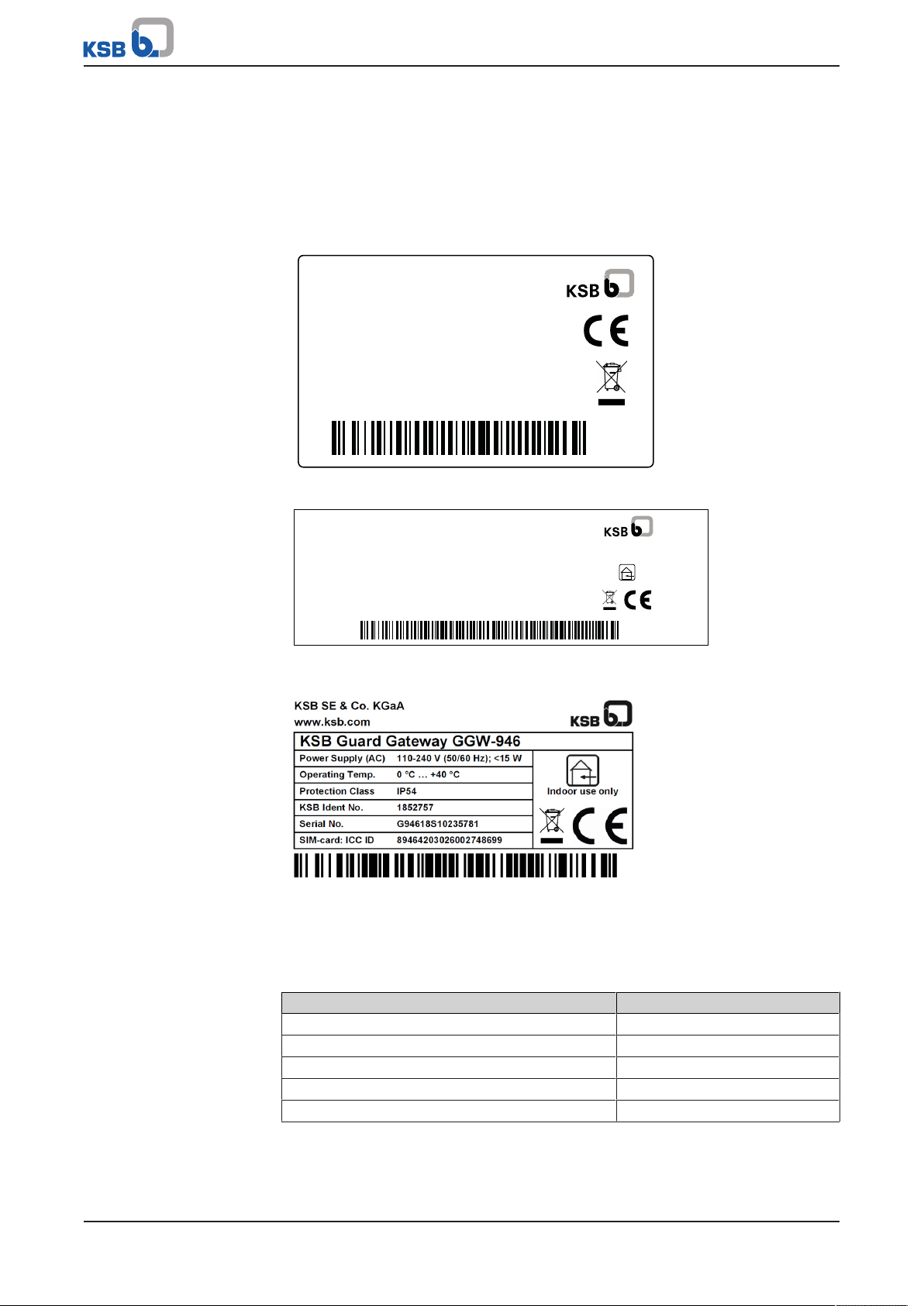
4.2 Name plates
Fig.1: Name plate of sensor unit
Sensor unit Table5: Technical data of sensor unit
Fig.2: Name plate of transmission and battery unit
Fig.3: Name plate of gateway
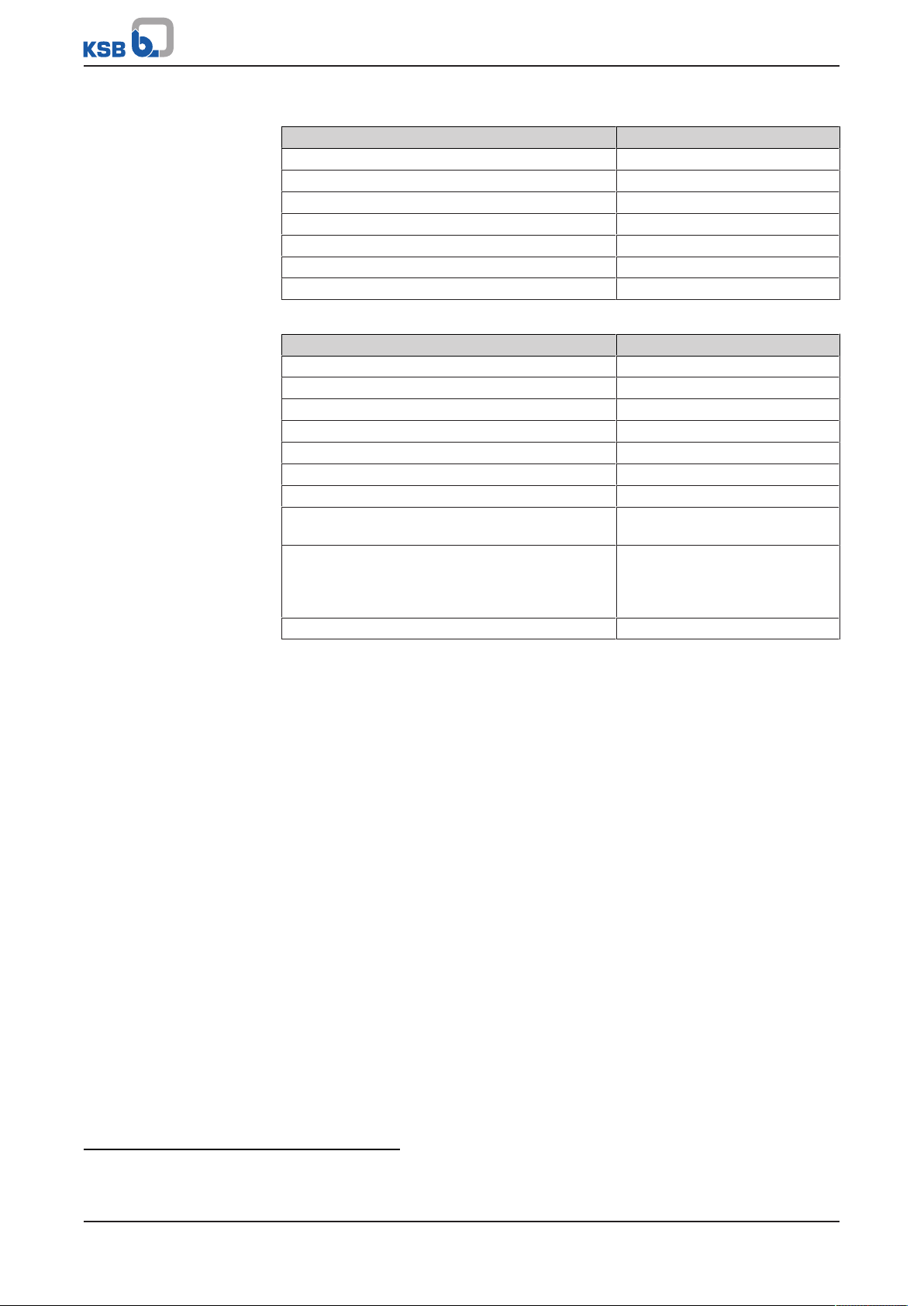
4.3 Technical data
Characteristic Value
Material Aluminium
Dimensions [mm] 60x45x30
Enclosure IP65
Cable type 1.5m, PUR, 6-pin
Ambient temperature ≤90°C
KSB Guard
11 of 40
Page 12
4 Description
Transmission and battery
unit
Gateway Table7: Technical data of gateway
Table6: Technical data of transmission and battery unit
Characteristic Value
Material Plastic
Dimensions [mm] 120x80x50
Enclosure IP65
Temperature range 0-50°C
Power supply 2 C size batteries (baby), (R14)
Wireless module ISM band, 2.4GHz
Connection M8, 6-pin
Characteristic Value
Mains voltage 110 - 240V, AC voltage
Mains frequency 50/60Hz
Power input <15W
In-service ambient temperature 0 to 40°C
1)
Enclosure IP54
Weight <400g
Dimensions 158×95×45
SMA-RP socket (antenna sensor network) Antenna for 2.4 GHz (WLAN/
Bluetooth)
SMA socket (LTE antenna) Antenna for 2G/3G/4G mobile
data, included in standard
accessories with approx. 5 m
cable
Internal SIM card
2)
Pre-configured
Transmission and battery
unit
Gateway One gateway can process the data of up to 20 transmission and battery units if they
4.4 Function
The sensor unit and transmission and battery unit are connected by a connecting
cable. The sensor unit is installed on the pump’s bearing bracket or drive lantern,
where it measures the pump’s vibration and temperature using built-in sensors.
This data is sent to the transmission and battery unit.
The transmission and battery unit sends the recorded data to the gateway via a radio
signal. From there, the data collected is transferred directly and in encrypted format
to the KSB Cloud for processing.
send data every hour. This number is reduced with more frequent data transmission.
1) Higher temperatures than indicated are possible. Contact KSB Support before installation. Contact: +49 6233 86 6400 and
ksbguard-support@ksb.com.
2) The SIM card is pre-installed and cannot be replaced.
12 of 40
KSB Guard
Page 13

4 Description
1 2 3 4 5
6
4.5 Gateway
Fig.4: Gateway
1 Antenna connection (data
transmission of transmission and
battery unit)
3 Status LED S1 for connection status 4 Level LEDs for mobile network
5 Antenna connection for mobile
data (LTE)
Table8: Description of LED indicators
No. LED Status Description
2 Supply voltage OFF Device is out of operation or in the initialisation phase.
Green Device is in operation. No faults present.
Red Device is in operation. Faults are present.
Flashing red Firmware update is being installed.
3 Connection status OFF No mobile network, no Internet
Yellow Mobile network accessible, no Internet
Green Mobile network and Internet accessible
4 Mobile network
signal strength
4th LED green Signal strength > -75dBm
3rd LED green Signal strength > -85dBm
2nd LED green Signal strength > -95dBm
1st LED green Signal strength < -95dBm
2 Status LED for supply voltage
signal strength (LTE)
6 Power supply connection
KSB Guard
13 of 40
Page 14

4 Description
1
2
1
2
5
6
3
4
4.6 Sensor unit
Fig.5: Sensor unit
1 QR code 2 Connecting cable to transmission
and battery unit
4.7 Transmission and battery unit
Fig.6: Transmission and battery unit
1 Pushbutton 2 Status LED A
3 Status LED B 4 Level LEDs for indicating the signal
strength of the gateway connection
5 Cover for housing screws 6 Connection for connecting cable to
sensor unit
Table9: Description/ function of control elements and LED indicators
Control element/ LED indicator Description
Pushbutton Commissioning, status check, manual measurement
Status LED A Status LEDs for indicating the operating status and for coded output of fault
Status LED B
Level LEDs Signal strength of the gateway connection
messages
14 of 40
KSB Guard
Page 15

5 Installation/Commissioning
5 Installation/Commissioning
5.1 Installation
5.1.1 Installing the gateway
DANGER
Risk of falling when working at a great height
Danger to life by falling from a great height!
▷ Do not step onto the pump (set) during installation work or dismantling work.
▷ Pay attention to safety equipment, such as railings, covers, barriers, etc.
▷ Observe the applicable local health and occupational safety regulations and
accident prevention regulations.
WARNING
Work in the immediate vicinity of rotating parts
Risk of hand injury!
▷ Always have this work performed by trained personnel.
▷ Take particular caution when performing this work.
CAUTION
Incorrect installation
No data transmission!
▷ Never connect more than 20 transmission and battery units to a gateway.
▷ Maintain a minimum distance of approx. 100m between 2 gateways (or use
separate rooms/ halls).
One gateway can process the data of up to 20 transmission and battery units if they
send data every hour. This number is reduced with more frequent data transmission.
The manufacturer must be consulted if more than 20 transmission and battery units
are connected or if the data transmission rate is higher.
NOTE
Adding another gateway will not serve to increase the data transmission rate or the
number of connected transmission and battery units. If several gateways are within
transmission range of each other, this can lead to overlap and interference.
5.1.1.1 Checking the installation location of the gateway
The installation location of the gateway must meet the following requirements:
▪ Temperature 0-40°C3) (ðSection4.3,Page11)
▪ Only install and operate the gateway in closed rooms.
▪ No direct sunlight
▪ At least 2 m above the ground
▪ Maximum distance between gateway and transmission and battery unit: 30m
▪ Area between gateway and transmission and battery unit with as few obstacles
as possible (e.g. walls).
If possible: Install with a direct visual connection between the pump set to be
connected and the gateway.
3) Higher temperatures than indicated are possible. Contact KSB Support for more information.
KSB Guard
15 of 40
Page 16

5 Installation/Commissioning
1
2
5.1.1.2 Installing the gateway antennas
Fig.7: Installing antennas
1 Rod antenna 2 Magnetic base antenna
The antenna cable should not exceed 20 m in length.
1. Screw the supplied rod antenna onto the left connection (Antenna sensor
network).
2. Screw the magnetic base antenna onto the right connection (Antenna LTE).
3. Place the magnetic base antenna in a location that has sufficiently high mobile
network signal strength. (ðSection5.1.1.4,Page17)
5.1.1.3 Electrically connecting the gateway
Connecting to a shockproof socket
1. Plug the mains power cable supplied into the socket.
2. Check the status LED.
Make sure that at least 2 LEDs are lit. This indicates that the connection to the
mobile network is sufficiently strong.
ð When the mains power cable is connected, the gateway starts automatically and
can then be used.
Alternative connection to customer’s own power supply
DANGER
Improper work on electrical connection
Electric shock!
▷ The gateway may only be opened by a qualified electrical technician.
▷ Electrical work may only be carried out by a qualified electrical technician.
Alternatively, the mains power cable supplied can also be replaced with the
customer’s own mains power cable:
16 of 40
KSB Guard
Page 17

5 Installation/Commissioning
1
Fig.8: Gateway
1 Screw terminals for power supply
1. Insert customer’s own mains power cable into the device through the cable
gland.
2. Connect the mains power cable to the appropriate screw terminals on the circuit
board.
When the customer’s own mains power cable is connected, the gateway starts
automatically and can then be used.
3. Check status LED S1.
Make sure that at least 2 level LEDs are lit. This indicates that the connection to
the mobile network is sufficiently strong.
ð When the mains power cable is connected, the gateway starts automatically and
can then be used.
NOTE
When connecting the cable ensure that the enclosure requirements (IP54) are met
again after installation.
5.1.1.4 Checking the signal strength of the gateway
The signal strength of the mobile data connection can be changed by positioning the
magnetic base antenna. The current signal strength is indicated by the corresponding
level LEDs (see Table: Description of LED indicators). (ðSection4.5,Page13)
▪ Minimum sufficient signal strength is indicated by 2 level LEDs lighting up.
▪ Good signal strength is indicated by 3 level LEDs lighting up.
▪ Maximum signal strength is indicated by 4 level LEDs lighting up.
It is recommended that you position the magnetic base antenna such that 3 or 4 level
LEDs are lit during installation. (ðSection4.5,Page13)
1. Place the magnetic base antenna in a location that has sufficiently high mobile
network signal strength.
2. Check the level LEDs for mobile network signal strength.
3. If necessary, change the position of the magnetic base antenna and check again.
If this condition cannot be met, check whether a more powerful LTE antenna can be
installed using a longer cable (if required). In this scenario, an LTE antenna suitable
for outdoor installation is recommended in particular.
The antenna cable should not exceed 20 m in length.
KSB Guard
17 of 40
Page 18

5 Installation/Commissioning
1
2
NOTE
To improve data transmission between the gateway and the transmission and
battery unit, you can rotate and tilt the gateway antenna (data transmission of
transmission and battery unit). The gateway antenna acts in the plane
perpendicular to the antenna’s axis. The transmission and battery unit should be in
this plane. (ðSection4.5,Page13)
5.1.1.5 Fastening the gateway
Fig.9: Fastening the wall bracket
1 Wall bracket 2 Bolts/screws
ü The gateway antennas have been fitted.
ü The gateway is connected to the power supply.
ü The signal strength at the installation location has been checked and is sufficient.
1. Attach the wall mounting bracket supplied to a suitable wall using 2 screws.
2. Connect the rear adapter of the gateway to the wall bracket.
5.1.2 Installing the sensor unit
DANGER
Strong magnetic field
Danger of death for persons with pacemaker!
Interference with magnetic data carriers, electronic devices, components and
instruments!
Uncontrolled magnetic attraction forces between magnet-equipped components,
tools or similar!
▷ Keep a safety distance of at least 0.3m.
WARNING
18 of 40
Hot surfaces of pump set
Risk of burns!
▷ Observe the manufacturer’s safety instructions for fastening the sensor unit and
using the adhesive.
KSB Guard
Page 19

5 Installation/Commissioning
WARNING
Sensor unit takes on temperature of bearing bracket or drive lantern
Risk of burns!
▷ Observe the operating manual of the pump set.
▷ When the pump set is being operated, only touch the sensor unit using suitable
protective gloves.
WARNING
Work in the immediate vicinity of rotating parts
Risk of hand injury!
▷ Always have this work performed by trained personnel.
▷ Take particular caution when performing this work.
Positioning the sensor unit Observe the following information when positioning and fastening the sensor unit:
▪ Mount the sensor unit at a suitable location on the bearing bracket or drive
lantern up to a maximum height of 2 m.
Recommended mounting position (ðSection10.1,Page32)
▪ Affix the sensor unit to magnetic material if possible (preferred).
▪ The location on the bearing bracket or drive lantern where the sensor unit is
mounted should be level. Use the adhesive to compensate for minor uneven
spots or curvatures.
▪ The sensor unit must also be glued in addition to the magnetic holders.
▪ (For further information on the correct mounting position, see www.ksb.com/
product/ksbguard).
ü The operating manual for the pump set is accessible and has been observed.
ü All safety instructions for the adhesive have been read and observed.
1. Remove any coarse dirt from the mounting area.
2. Clean the back of the sensor unit using the supplied cleaning pad.
3. Clean the mounting area using the supplied cleaning pad.
4. Spread the supplied adhesive over the back of the sensor unit.
5. Position the sensor unit on the cleaned area of the bearing bracket or drive
lantern. The sensor unit is optimally aligned when one axis of the sensor unit is
parallel to the shaft and the other axis of the sensor unit is horizontal to the
shaft.
6. Firmly press down the sensor unit.
7. Allow the sensor unit to dry on the bearing bracket or drive lantern to ensure
that the position of the sensor unit is not unintentionally changed during
subsequent mounting. The adhesive bond must be able to withstand slight
vibrations at the sensor unit. The waiting time heavily depends on ambient
conditions.
NOTE
At an ambient temperature between +25 °C and +30 °C, the supplied adhesive will
have sufficiently cured after approximately 24 hours. After 3 days, the adhesive will
have fully cured. Increased temperatures (e.g. +60°C to +120°C) accelerate the
curing process.
8. Check that the sensor unit is firmly positioned on the bearing bracket or drive
lantern; re-glue the sensor unit if necessary.
KSB Guard
19 of 40
Page 20

5 Installation/Commissioning
1
2
5
6
3
4
5.1.3 Establishing a connection between the sensor unit and the transmission and battery unit
NOTE
The adhesive bond between the sensor unit and bearing bracket or drive lantern
must be sufficiently cured before continuing to install the connecting cable to avoid
changing the position of the sensor unit.
1. Connect the connecting cable of the sensor unit to the transmission and battery
unit.
5.1.4 Commissioning
Supplied condition The transmission and battery unit is delivered in Deep Sleep mode
(ðSection6.1,Page25) . This operating mode remains active until commissioning
has been completed successfully.
During commissioning, a sensor unit must be detected and a functioning gateway
found within wireless range.
If commissioning is not successful, the device remains in Deep Sleep mode until it is
woken up by pressing and holding down the relevant button.
Commissioning
Fig.10: Transmission and battery unit
1 Pushbutton 2 Status LED A
3 Status LED B 4 Level LEDs for indicating the signal
strength of the gateway connection
5 Cover for housing screws 6 Connection for connecting cable to
sensor unit
ü The gateway has been installed and the signal strength indicated is sufficient.
ü The sensor has been fitted at a suitable location on the pump set.
ü The sensor unit and the transmission and battery unit are interconnected and the
power cable has been connected.
1. Press and hold the pushbutton (1) on the transmission and battery unit for 3
seconds. Release the pushbutton as soon as status LEDs A and B of the
transmission and battery unit briefly light up simultaneously.
ð All LEDs of the transmission and battery unit flash in a predefined sequence and
extinguish. The device is now in stand-by mode and commissioning/ start-up was
successful.
ð Commissioning/ start-up must be repeated if the LEDs of the transmission and
battery unit do not light up after a brief waiting period.
20 of 40
KSB Guard
Page 21

5 Installation/Commissioning
5.1.5 Installing the transmission and battery unit
The transmission and battery unit can be freely positioned as long as the transmission
quality to the gateway is sufficient. (ðSection5.1.4,Page20)
WARNING
Work in the immediate vicinity of rotating parts
Risk of hand injury!
▷ Always have this work performed by trained personnel.
▷ Take particular caution when performing this work.
The area selected should have the following properties:
▪ Temperature of substrate ≤ 50°C
▪ Position protected
▪ Level
▪ Maximum ground clearance 2 m
ü Electrical connection between sensor unit and transmission and battery unit has
been established.
ü Batteries have been inserted. (Supplied condition)
ü Signal strength at installation location is sufficient. (ðSection6.2,Page25)
1. Position the transmission and battery unit such that there is a line of sight to the
gateway if possible. In the process, ensure that the connecting point of the
connecting cable can be easily accessed.
2. Clean the surface of the transmission and battery unit using the supplied alcohol
pads.
3. Securely attach the transmission and battery unit using the supplied fastening
material.
5.1.6 Routing the connecting cable
WARNING
Work in the immediate vicinity of rotating parts
Risk of hand injury!
▷ Always have this work performed by trained personnel.
▷ Take particular caution when performing this work.
WARNING
Hot surfaces (Pump and piping take on the temperature of the fluid handled.)
Risk of burns!
▷ Do not touch hot surfaces.
CAUTION
Improper routing
Damage to the connecting cable!
▷ Never kink or crush the connecting cable.
KSB Guard
21 of 40
Page 22

5 Installation/Commissioning
Fig.11: Routing the connecting cable
1. Secure the connecting cable between the sensor unit and the transmission and
battery unit in such a way that no hazard (tripping, entrapment) can arise from
it.
2. Roll up excess length of connecting cable and fasten it using the supplied
fastening material.
5.2 Commissioning the gateway
The device is delivered fully configured and is ready for operation after the power
supply has been connected. The current operating status is indicated by the LED for
the supply voltage. (ðSection4.5,Page13)
22 of 40
KSB Guard
Page 23

5 Installation/Commissioning
5.3 Assigning and setting up
NOTE
The sensor unit must be initially assigned to a pump set.
This assignment cannot be subsequently undone and remains valid for the service
life of the sensor unit.
Correct assignment is key to ensuring proper functionality of the device.
Measurement data can only be saved after the assignment has been made.
You can make the assignment on the KSBGuard Web Portal (www.ksbguard.net) or
in the KSBGuard app (available for iOS and Android).
Further data will be required as you continue setting up the KSB Guard app. We
recommend that you collect the data in advance so that it is readily available when
you need it. The following data is required:
Table10: Data required to register the pump set in the KSBGuard app
Required data Example Notes
Serial number of the sensor unit
(ðSection4.6,Page14)
Designation of the pump set Pump 123
Location of the pump set Hall 2
Functional location of the pump set B2411
Optional: Photo of the pump set/pump
Data from the pump name plate
Manufacturer KSB
Year of construction 2018
Serial number
4)
Type series Etanorm
Size 050-032-161
Nominal head 25 m
Nominal flow rate 50m³/h
Nominal speed 1450rpm
Number of stages 1
Operating hours of the pump set to date (initial
value for the operating hours counter)
Data from the motor name plate
Nominal power 15kW
Nominal speed 1450 rpm
Power factor (cosϕ) 0,86
Other details
Variable speed system (yes or no) No
Application of the pump Heat supply system
Fluid temperature +20°C to +30°C
Density of the fluid handled 997 kg/m³
Bearing type and, if applicable, operating hours
since most recent bearing lubrication/
replacement
GS118W220071
997123456700010000
1000h
Grease, re-lubrication, 1000 h
4) With a pump set from KSB, data on the pump can be accessed when necessary. To do this, it is important that you enter the
KSB serial number in the corresponding field of the app/ web portal. If data is available, it is also displayed in the app or on
the web portal and must be checked to ensure that it is accurate and up to date.
KSB Guard
23 of 40
Page 24

5 Installation/Commissioning
Required data Example Notes
Optional: Optimum flow rate 50 m³/h
Optional: Specification of 7 reference points on
the characteristic curve
ü The KSB Guard app is installed on the mobile device.
ü Data as per table The data required to register the pump set in the KSBGuard app is
available.
1. Start the KSB Guard app or open the KSB Guard Web Portal
(www.ksbguard.net).
2. Select the Add Pump function in the app menu or on the web portal.
3. Follow the instructions in the app dialogue or on the web portal and enter the
requested information.
4. Save the assignment.
25kW, 25m³/h, 25 m;
20kW…
NOTE
The limit values for the pump set are set automatically. Default values can be
checked and, if necessary, changed in the individual view screen of the pump.
NOTE
Once the link has been established, 2 measuring cycles must be run through until
the data transferred from the pump set can be viewed on the web portal or in the
app. This process takes 2 hours at minimum for hourly data transfer (default
setting). If 2 measurements are triggered manually (ðSection6.2,Page25) , the
data can be viewed in just a few minutes’ time.
24 of 40
KSB Guard
Page 25

6 Operation
6 Operation
6.1 Operating modes of transmission and battery unit
▪ Deep Sleep
Status of the device before commissioning and after the batteries have been
removed for more than 10 s.
▪ Stand-by mode
After successful commissioning/ start-up, the device automatically switches to
stand-by mode following each measuring and transfer cycle to save energy. In
this status, all LEDs are off. The device wakes up cyclically (default setting: every
hour) and takes an automatic measurement.
6.2 Taking manual measurement and displaying signal strength
WARNING
Hot surfaces (Pump and piping take on the temperature of the fluid handled.)
Risk of burns!
▷ Do not touch hot surfaces.
WARNING
Sensor unit takes on temperature of bearing bracket or drive lantern
Risk of burns!
▷ Observe the operating manual of the pump set.
▷ When the pump set is being operated, only touch the sensor unit using suitable
protective gloves.
WARNING
Work in the immediate vicinity of rotating parts
Risk of hand injury!
▷ Always have this work performed by trained personnel.
▷ Take particular caution when performing this work.
ü Commissioning was completed successfully. (ðSection5.1.4,Page20)
1. Briefly press the pushbutton on the transmission and battery unit.
ð The most recent transmission status is displayed.
2. Wait until status LEDs A and B flash slowly (0.5 Hz) together.
3. Briefly press the pushbutton on the transmission and battery unit again.
ð Manual measurement, signal strength is displayed and data is transmitted.
The level LEDs that indicate the signal strength light up briefly after a short
waiting time.
After the measurement is taken, the device automatically switches to stand-by mode
and all LEDs extinguish.
6.3 Reading out the transmission status
ü Commissioning was completed successfully. (ðSection5.1.4,Page20)
1. Briefly press the pushbutton on the transmission and battery unit.
ð The most recent transmission status is displayed.
The transmission status display is complete when status LEDs A and B flash slowly
together (0.5 Hz).
You can now trigger manual measurement if required. (ðSection6.2,Page25)
KSB Guard
25 of 40
Page 26

6 Operation
The device then automatically switches to stand-by mode and all LEDs extinguish.
26 of 40
KSB Guard
Page 27

7 Changing the Batteries
1
1
7 Changing the Batteries
The transmission and battery unit uses two 1.5V batteries.
Only non-rechargeable, standard alkaline batteries (size R14/ baby/ size C) may be
used. Do not insert any other type of battery.
CAUTION
Electrical connection work by unqualified personnel
Damage to the device!
▷ Only trained personnel may open the transmission and battery unit and change
the batteries.
NOTE
During battery replacement, ensure that the foamed-in housing gasket does not
become damaged.
Fig.12: Cover for housing screws
1 Cover for housing screws
1. Remove the glued-on covers for the housing screws (1) from the top of the
housing using a suitable tool.
2. Unscrew the 4 screws in the corners.
3. Pull off the upper part of the housing.
4. Carefully remove the used batteries from the holder, then wait approximately
10 seconds.
5. Insert 2 new batteries. Ensure correct polarity.
The prescribed polarity (+/-) is indicated by corresponding symbols on the circuit
board.
6. Briefly press the pushbutton on the top of the housing and check whether red
status LED A lights up briefly. If status LED A does not light up, check the battery
polarity or insert other batteries.
7. Place the upper part of the housing back on the housing assembly.
8. Screw the 4 screws back into the corners.
9. Glue both covers for the housing screws (1) back on.
10. Restart the transmission and battery unit. (ðSection5.1.4,Page20)
KSB Guard
27 of 40
Page 28

8 Dismantling
8 Dismantling
WARNING
Incorrect dismantling
Crushing, impact injuries, cuts!
▷ Use suitable tools only.
▷ Wear suitable protective equipment.
8.1 Dismantling the gateway
DANGER
Risk of falling when working at a great height
Danger to life by falling from a great height!
▷ Do not step onto the pump (set) during installation work or dismantling work.
▷ Pay attention to safety equipment, such as railings, covers, barriers, etc.
▷ Observe the applicable local health and occupational safety regulations and
accident prevention regulations.
DANGER
Improper work on electrical connection
Electric shock!
▷ The gateway may only be opened by a qualified electrical technician.
▷ Electrical work may only be carried out by a qualified electrical technician.
1. Disconnect the power supply.
2. Detach the rear adapter of the gateway from the wall bracket.
3. Remove the wall-mounting bracket from the wall.
8.2 Dismantling the transmission and battery unit
WARNING
Work in the immediate vicinity of rotating parts
Risk of hand injury!
▷ Always have this work performed by trained personnel.
▷ Take particular caution when performing this work.
WARNING
Hot surfaces (Pump and piping take on the temperature of the fluid handled.)
Risk of burns!
▷ Do not touch hot surfaces.
28 of 40
1. Disconnect the connecting cable of the sensor unit.
2. Carefully remove the transmission and battery unit from the installation
location. Use a lever tool if necessary.
KSB Guard
Page 29

8 Dismantling
8.3 Dismantling the sensor unit
DANGER
Strong magnetic field
Danger of death for persons with pacemaker!
Interference with magnetic data carriers, electronic devices, components and
instruments!
Uncontrolled magnetic attraction forces between magnet-equipped components,
tools or similar!
▷ Keep a safety distance of at least 0.3m.
WARNING
Work in the immediate vicinity of rotating parts
Risk of hand injury!
▷ Always have this work performed by trained personnel.
▷ Take particular caution when performing this work.
WARNING
Hot surfaces (Pump and piping take on the temperature of the fluid handled.)
Risk of burns!
▷ Do not touch hot surfaces.
ü The connecting cable leading to the transmitter and battery unit has been
removed.
1. Tap off the sensor unit using a soft-face mallet.
KSB Guard
29 of 40
Page 30

9 Trouble-shooting
9 Trouble-shooting
If problems occur that are not described in the following tables, consultation with
KSBGuard Customer Service is required:
▪ 24-h hotline : +49 6233 86 6400
▪ E-mail: ksbguard-support@ksb.com
NOTE
To ensure quick assistance, have the serial number of the sensor unit readily
available.
9.1 Trouble-shooting the gateway
Table11: Gateway trouble-shooting
Error/ defect description Possible cause Remedy
No LED is lit. No connection to mains power
supply
Only one or no green level LED is lit at
the gateway, but status LED S1 is lit
green.
Status LED S1 remains off for more
than 1 minute after the power supply
has been established or is lit yellow.
▪ Solid exterior walls
▪ Great deal of metal in the
surrounding area
▪ Unfavourable position in the
basement of the building
▪ Poor mobile data connection
at the location
Internal fault ▪ Contact KSBGuard Customer
▪ Plug in the mains plug or connect
the mains voltage internally in the
device. (ðSection5.1.1.3,Page16)
▪ Change the position of the
supplied LTE antenna until 3 or 4
level LEDs light up.
▪ If necessary, install an additional
LTE antenna with a longer cable to
achieve a more favourable
position.
(ðSection5.1.1.4,Page17)
▪ Install an outdoor LTE antenna
outside the building.
Service.
9.2 Trouble-shooting the transmission and battery unit/ sensor unit
Table12: Trouble-shooting during commissioning
Error/ defect description Possible cause Remedy
There is no response to a brief press of
the pushbutton.
A brief press of the button produces a
longer flashing sequence (last
transmission status displayed).
▪ The battery is missing or is
discharged.
▪ System error
▪ The system has already been
commissioned.
▪ Change the batteries.
(ðSection7,Page27)
▪ Remove the batteries for 10s, then
reinsert.
▪ Contact KSBGuard Customer
Service.
▪ The device may have been
inadvertently commissioned.
Remove the batteries for 10s, then
reinsert.
Then perform commissioning.
(ðSection5.1.4,Page20)
30 of 40
KSB Guard
Page 31

9 Trouble-shooting
Error/ defect description Possible cause Remedy
After an extended press of the button,
none of the red level LEDs for the
transmission and battery unit light up.
KSG Guard does not send any data to
the KSB Cloud or does not yet appear
there.
Table13: Trouble-shooting during operation
Error/ defect description Possible cause Remedy
KSBGuard does not provide any data
following successful assignment.
Data is suddenly no longer transmitted
during operation, or there are
frequently large time gaps between 2
transfer cycles.
▪ Gateway is switched off. ▪ Switch on gateway.
▪ Gateway is out of range. ▪ If possible, place the transmission
and battery unit within wireless
range of the gateway and test
again.
▪ Sensor unit has not yet been
connected or is defective.
▪ KSB Guard has not been
assigned to a pump set.
▪ Problem in the KSB Cloud
▪ Hardware is defective.
▪ Poor LTE connection ▪ (ðSection9.1,Page30)
▪ The wireless connection
between the transmission and
battery unit and the gateway
is too weak or unstable (local
interference).
▪ Check the connection between the
transmission and battery unit and
the sensor unit, and replace the
sensor if required.
▪ Assign KSB Guard to a pump set
(ðSection5.3,Page23) .
▪ Contact KSBGuard Customer
Service.
▪ Trigger manual measurement
(ðSection6.2,Page25) and check
result. If less than 2 red level LEDs
on the transmission and battery
unit light up, change the position
of the transmission and battery
unit and/or gateway.
(ðSection5.1.5,Page21)
(ðSection5.1.1.1,Page15)
KSB Guard
31 of 40
Page 32

10 Related Documents
10 Related Documents
10.1 Recommended mounting position for sensor unit
The position of the sensor unit as shown in the illustrations is recommended,
depending on the type series.
Fig.13: Etanorm mit Sensoreinheit
Fig.14: Etaline with sensor unit
32 of 40
Fig.15: Etabloc with sensor unit
KSB Guard
Page 33

10 Related Documents
Fig.16: Etaline R with sensor unit
Fig.17: MegaCPK with sensor unit
Fig.18: Movitec with sensor unit
KSB Guard
33 of 40
Page 34

10 Related Documents
Fig.19: Multitec with sensor unit
Fig.20: Omega with sensor unit
Fig.21: Sewatec with sensor unit
34 of 40
KSB Guard
Page 35

11 EU Declaration of Conformity
11 EU Declaration of Conformity
Manufacturer: KSB SE & Co. KGaA
Johann-Klein-Straße 9
67227 Frankenthal (Germany)
This Declaration of Conformity is issued under the sole responsibility of the manufacturer.
The manufacturer herewith declares that the product:
KSB Guard
Serial number ranges:
KSB Guard sensor unit: GS118W22xxxx to GS130W52xxxx
KSB Guard transmission and battery unit: GT118W22xxxx to GT130W52xxxx
KSB Guard gateway: G94618S22xxxxxx to G94630S52xxxxxx
▪ is in conformity with the provisions of the following Directives as amended from time to time:
– 2014/53/EU: Radio Equipment Directive (RED)
– 2011/65/EU: Restriction of the Use of Certain Hazardous Substances in Electrical and Electronic Equipment
(RoHS)
The manufacturer also declares that the following harmonised international standards have been applied:
▪ KSB Guard sensor unit and KSB Guard transmission and battery unit
– IEC 60529 (2nd edition): 2013-08
– IEC 62368-1: 2014 (2nd edition) and Cor. 1: 2015
– EN 62368-1: 2014/AC: 2015/ A11:2017
– ETSI EN 300 328 V2.1.1
– ETSI EN 301 489-1 V2.2.0: 2017-03
– ETSI EN 301 489-17 V3.2.0: 2017-03
▪ KSB Guard gateway
– ETSI EN 300 328 V2.1.1
– DIN EN 55024:2016-05
– DIN EN 55032:2016-02
– EN 62368-1:2014 + AC:2015-05 + AC:2015-11
The EU Declaration of Conformity was issued in/on:
Frankenthal, 1 Sept. 2018
Thomas Paulus
Head of TPD, Digital Transformation
KSB SE & Co. KGaA
Johann-Klein-Straße 9
67227 Frankenthal
KSB Guard
35 of 40
Page 36

Index
Index
numerical
24-h hotline30
A
Adhesive curing19
Antennas16
Assignment
Sensor unit23
Automatic measurement25
B
Batteries27
C
Changing the batteries27
Commissioning20
Connecting cable20
Control elements
Transmission and battery unit14
Cover for housing screws27
Customer’s own mains power cable17
D
Deep Sleep20, 25
Dismantling
Gateway28
Sensor unit29
Transmission and battery unit28
Disposal10
E
EU Declaration of Conformity35
Event of damage5
F
Faults
Trouble-shooting31
Trouble-shooting the gateway30
Trouble-shooting the transmission and battery
unit/ sensor unit30
Function12
G
Gateway13, 17, 18, 22
LED indicators13
I
Improving data transmission18
Installation
Transmission and battery unit21
Installation location
Gateway15
Sensor unit19
Installing the transmission and battery unit21
Intended use7
K
Key to safety symbols/markings5
KSBGuard app24
KSBGuard Customer Service30
L
LED indicators
Gateway13
Transmission and battery unit14
Limits24
M
Magnetic base antenna17
Manual measurement25
Mounting position32
N
Name plate11
O
Operating modes25
Other applicable documents5
P
Positioning the sensor unit19
Power supply16
R
Registration23
Routing the connecting cable22
S
Safety7
Safety awareness8
Sensor unit14, 19
Signal strength of the mobile data connection17
Stand-by mode25
Storage9
Supplied condition20, 21
36 of 40
KSB Guard
Page 37

Index
T
Technical data
Gateway12
Sensor unit11
Transmission and battery unit12
Transmission and battery unit14, 20
LED indicators14
Transmission status25
Transport9
Trouble-shooting30
W
Wall bracket18
Warnings5
Warranty claims5
KSB Guard
37 of 40
Page 38

Page 39

Page 40

KSB SE & Co. KGaA
Johann-Klein-Straße 9 • 67227 Frankenthal (Germany)
Tel. +49 6233 86-0
www.ksb.com
4079.8/01-EN
 Loading...