

KSB Etaprime L Operating Manual
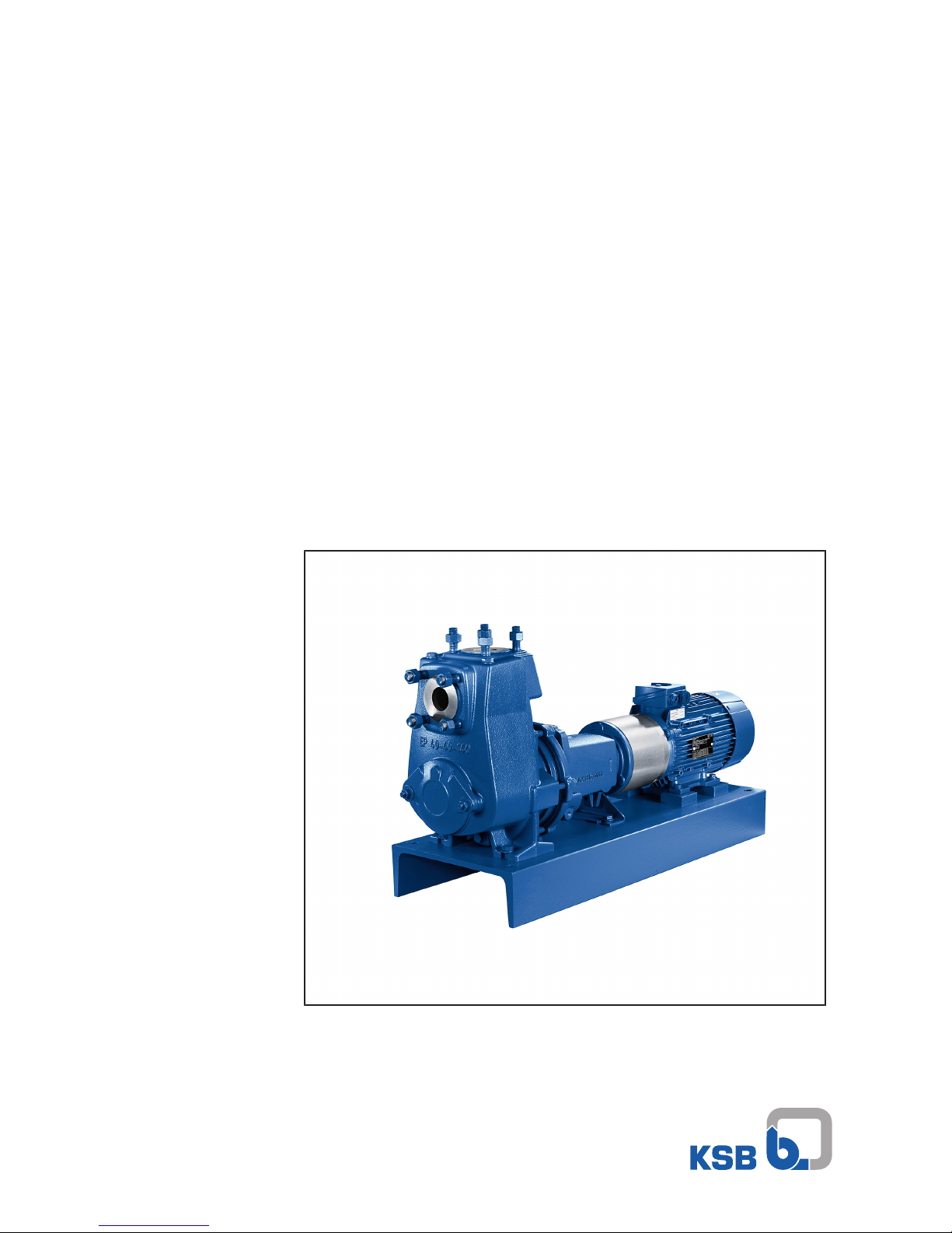
Self-priming Pump
Etaprime L
Installation/Operating Manual

Legal information/Copyright
Installation/Operating Manual Etaprime L
Original operating manual
All rights reserved. The contents provided herein must neither be distributed, copied, reproduced,
edited or processed for any other purpose, nor otherwise transmitted, published or made available to a
third party without the manufacturer's express written consent.
Subject to technical modification without prior notice.
© KSB ITUR Spain, S.A., Zarautz, España 13/06/2017

Contents
3 of 76
Etaprime L
Contents
Glossary .................................................................................................................................................. 6
1 General.................................................................................................................................................... 7
1.1 Principles ...........................................................................................................................................................7
1.2 Installation of partly completed machinery....................................................................................................7
1.3 Target group.....................................................................................................................................................7
1.4 Other applicable documents............................................................................................................................7
1.5 Symbols .............................................................................................................................................................7
2 Safety...................................................................................................................................................... 9
2.1 Key to safety symbols/markings.......................................................................................................................9
2.2 General..............................................................................................................................................................9
2.3 Intended use .....................................................................................................................................................9
2.4 Personnel qualification and training.............................................................................................................10
2.5 Consequences and risks caused by non-compliance with this manual .......................................................10
2.6 Safety awareness ............................................................................................................................................10
2.7 Safety information for the operator/user.....................................................................................................11
2.8 Safety information for maintenance, inspection and installation ..............................................................11
2.9 Unauthorised modes of operation................................................................................................................11
2.10 Explosion protection ......................................................................................................................................11
2.10.1 Marking ..............................................................................................................................................12
2.10.2 Temperature limits.............................................................................................................................12
2.10.3 Monitoring equipment......................................................................................................................13
2.10.4 Operating limits .................................................................................................................................13
3 Transport/Temporary Storage/Disposal............................................................................................. 14
3.1 Checking the condition upon delivery..........................................................................................................14
3.2 Transport.........................................................................................................................................................14
3.3 Storage/preservation......................................................................................................................................15
3.4 Return to supplier...........................................................................................................................................15
3.5 Disposal ...........................................................................................................................................................16
4 Description of the Pump (Set)............................................................................................................. 17
4.1 General description ........................................................................................................................................17
4.2 Designation.....................................................................................................................................................17
4.3 Name plate......................................................................................................................................................17
4.4 Design details..................................................................................................................................................18
4.5 Design and function.......................................................................................................................................19
4.6 Noise characteristics .......................................................................................................................................19
4.7 Dimensions and weights ................................................................................................................................20
4.8 Scope of supply...............................................................................................................................................20
5 Installation at Site................................................................................................................................ 21
5.1 Safety regulations...........................................................................................................................................21
5.2 Checks to be carried out prior to installation...............................................................................................21
5.3 Installing the pump set ..................................................................................................................................21
5.3.1 Installation on the foundation..........................................................................................................22
5.3.2 Installation without foundation .......................................................................................................23
5.4 Piping ..............................................................................................................................................................23
5.4.1 Connecting the piping.......................................................................................................................23
5.4.2 Permissible forces and moments at the pump nozzles....................................................................25
5.4.3 Auxiliary connections.........................................................................................................................26
5.5 Enclosure/insulation .......................................................................................................................................26
5.6 Checking the coupling alignment .................................................................................................................27
5.7 Aligning the pump and motor ......................................................................................................................28
5.7.1 Motors with adjusting screw.............................................................................................................28
5.7.2 Motors without adjusting screw ....................................................................................................... 29
5.8 Electrical connection ......................................................................................................................................30

Contents
4 of 76
Etaprime L
5.8.1 Setting the time relay ........................................................................................................................30
5.8.2 Earthing ..............................................................................................................................................30
5.8.3 Connecting the motor .......................................................................................................................31
5.9 Checking the direction of rotation................................................................................................................31
6 Commissioning/Start-up/Shutdown................................................................................................... 32
6.1 Commissioning/Start-up.................................................................................................................................32
6.1.1 Prerequisites for commissioning/start-up ......................................................................................... 32
6.1.2 Filling in the lubricants ...................................................................................................................... 32
6.1.3 Priming and venting the pump.........................................................................................................33
6.1.4 Final check ..........................................................................................................................................34
6.1.5 Start-up............................................................................................................................................... 34
6.1.6 Checking the shaft seal......................................................................................................................37
6.1.7 Shutdown ...........................................................................................................................................37
6.2 Operating limits..............................................................................................................................................38
6.2.1 Ambient temperature........................................................................................................................38
6.2.2 Frequency of starts.............................................................................................................................39
6.2.3 Fluid handled .....................................................................................................................................39
6.3 Shutdown/storage/preservation ....................................................................................................................40
6.3.1 Measures to be taken for shutdown ................................................................................................40
6.4 Returning to service .......................................................................................................................................41
7 Servicing/Maintenance........................................................................................................................ 42
7.1 Safety regulations...........................................................................................................................................42
7.2 Servicing/inspection........................................................................................................................................43
7.2.1 Supervision of operation ................................................................................................................... 43
7.2.2 Inspection work..................................................................................................................................45
7.2.3 Lubrication and lubricant change of rolling element bearings ...................................................... 46
7.3 Drainage/cleaning ..........................................................................................................................................49
7.4 Dismantling the pump set..............................................................................................................................49
7.4.1 General information/Safety regulations...........................................................................................49
7.4.2 Preparing the pump set..................................................................................................................... 50
7.4.3 Removing the motor..........................................................................................................................50
7.4.4 Removing the back pull-out unit ...................................................................................................... 50
7.4.5 Removing the impeller ......................................................................................................................51
7.4.6 Dismantling the mechanical seal ......................................................................................................51
7.4.7 Dismantling the bearings ..................................................................................................................52
7.5 Reassembling the pump set...........................................................................................................................52
7.5.1 General information/Safety regulations...........................................................................................52
7.5.2 Installing the bearings .......................................................................................................................53
7.5.3 Installing the mechanical seal ...........................................................................................................54
7.5.4 Fitting the impeller ............................................................................................................................56
7.5.5 Installing the back pull-out unit .......................................................................................................57
7.5.6 Mounting the motor .........................................................................................................................57
7.6 Tightening torques.........................................................................................................................................57
7.6.1 Tightening torques for the pump.....................................................................................................57
7.6.2 Tightening torques for the pump set ............................................................................................... 58
7.7 Spare parts stock.............................................................................................................................................59
7.7.1 Ordering spare parts.......................................................................................................................... 59
7.7.2 Recommended spare parts stock for 2 years' operation to DIN 24296 ..........................................59
7.7.3 Interchangeability of EtaprimeL and EtaprimeB pump components ...........................................60
8 Trouble-shooting.................................................................................................................................. 61
9 Related Documents.............................................................................................................................. 63
9.1 Sectional drawing and list of components ...................................................................................................63
9.1.1 Etaprime G and C, threaded connection, with bearing housing (SU17) .......................................63
9.1.2 Etaprime G and C, flanged connection, with bearing bracket/grease lubrication (SU25 and
SU35)..................................................................................................................................................65
9.1.3 Etaprime G and C, flanged connection, with bearing bracket/oil lubrication (SU25 and SU35) .....
69

Contents
5 of 76
Etaprime L
10 EU Declaration of Conformity............................................................................................................. 70
11 Certificate of Decontamination........................................................................................................... 71
Index ..................................................................................................................................................... 72

Glossary
6 of 76
Etaprime L
Glossary
Back pull-out design
The complete back pull-out unit can be pulled out
without having to remove the pump casing from
the piping.
Back pull-out unit
Pump without pump casing; partly completed
machinery
Certificate of decontamination
A certificate of decontamination is enclosed by the
customer when returning the product to the
manufacturer to certify that the product has been
properly drained to eliminate any environmental
and health hazards arising from components in
contact with the fluid handled.
Discharge line
The pipeline which is connected to the discharge
nozzle
Hydraulic system
The part of the pump in which the kinetic energy
is converted into pressure energy
Noise characteristics
The noise characteristics are indicated as surface
sound pressure level in dB(A).
Pool of pumps
Customers/operators’ pumps which are purchased
and stored regardless of their later use.
Pump
Machine without drive, additional components or
accessories
Pump set
Complete pump set consisting of pump, drive,
additional components and accessories
Self-priming ability
Ability of a filled pump to evacuate a suction line,
i.e. to self-prime from an unfilled suction line.
Suction lift line/suction head line
The pipeline which is connected to the suction
nozzle
1 General
7 of 76
Etaprime L
1 General
1.1 Principles
This operating manual is supplied as an integral part of the type series and variants
indicated on the front cover. The manual describes the proper and safe use of this
equipment in all phases of operation.
The name plate indicates the type series and size, the main operating data, the order
number and the order item number. The order number and order item number
clearly identify the pump set and serve as identification for all further business
processes.
In the event of damage, immediately contact your nearest KSB service centre to
maintain the right to claim under warranty.
Observe the noise characteristics, indicated as surface sound pressure level.
(ðSection4.6,Page19)
1.2 Installation of partly completed machinery
To install partly completed machinery supplied by KSB refer to the sub-sections under
Servicing/Maintenance. (ðSection7.5.5,Page57)
1.3 Target group
This operating manual is aimed at the target group of trained and qualified specialist
technical personnel. (ðSection2.4,Page10)
1.4 Other applicable documents
Table1: Overview of other applicable documents
Document Contents
Data sheet Description of the technical data of the pump (set)
General arrangement drawing/
outline drawing
Description of mating and installation dimensions
for the pump (set), weights
Drawing of auxiliary connections Description of auxiliary connections
Hydraulic characteristic curve Characteristic curves showing head, NPSH
required, efficiency and power input
General assembly drawing
1)
Sectional drawing of the pump
Sub-supplier product literature1)Operating manuals and other product literature
describing accessories and integrated machinery
components
Spare parts lists
1)
Description of spare parts
Piping layout
1)
Description of auxiliary piping
List of components
1)
Description of all pump components
Drawing for assembly
1)
Sectional drawing of the installed shaft seal
For accessories and/or integrated machinery components observe the relevant
manufacturer's product literature.
1.5 Symbols
Table2: Symbols used in this manual
Symbol Description
✓ Conditions which need to be fulfilled before proceeding with the
step-by-step instructions
⊳ Safety instructions
⇨ Result of an action
1) If agreed upon in scope of supply

1 General
8 of 76
Etaprime L
Symbol Description
⇨ Cross-references
1.
2.
Step-by-step instructions
Note
Recommendations and important information on how to handle
the product
2 Safety
9 of 76
Etaprime L
2 Safety
!
DANGER
All the information contained in this section refers to hazardous situations.
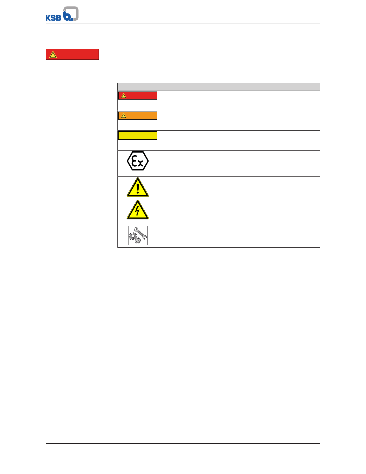
2.1 Key to safety symbols/markings
Table3: Definition of safety symbols/markings
Symbol Description
!
DANGER
DANGER
This signal word indicates a high-risk hazard which, if not avoided,
will result in death or serious injury.
!
WARNING
WARNING
This signal word indicates a medium-risk hazard which, if not
avoided, could result in death or serious injury.
CAUTION
CAUTION
This signal word indicates a hazard which, if not avoided, could
result in damage to the machine and its functions.
Explosion protection
This symbol identifies information about avoiding explosions in
potentially explosive atmospheres in accordance with Directive
2014/34/EU (ATEX).
General hazard
In conjunction with one of the signal words this symbol indicates a
hazard which will or could result in death or serious injury.
Electrical hazard
In conjunction with one of the signal words this symbol indicates a
hazard involving electrical voltage and identifies information about
protection against electrical voltage.
Machine damage
In conjunction with the signal word CAUTION this symbol indicates
a hazard for the machine and its functions.
2.2 General
This operating manual contains general installation, operating and maintenance
instructions that must be observed to ensure safe operation of the system and
prevent personal injury and damage to property.
The safety information in all sections of this manual must be complied with.
The operating manual must be read and understood by the responsible specialist
personnel/operators prior to installation and commissioning.
The contents of this operating manual must be available to the specialist personnel
at the site at all times.
Information attached directly to the product must always be complied with and kept
in a perfectly legible condition at all times. This applies to, for example:
▪ Arrow indicating the direction of rotation
▪ Markings for connections
▪ Name plate
The operator is responsible for ensuring compliance with all local regulations not
taken into account in this operating manual.
2.3 Intended use
▪ The pump (set) must only be operated within the operating limits described in
the other applicable documents. (ðSection1.4,Page7)
▪ Only operate pumps/pump sets which are in perfect technical condition.
▪ Do not operate the pump (set) in partially assembled condition.

2 Safety
10 of 76
Etaprime L
▪ Only use the pump to handle the fluids described in the data sheet or product
literature of the pump model or variant.
▪ Never operate the pump without the fluid to be handled.
▪ Observe the minimum flow rates indicated in the data sheet or product literature
(to prevent overheating, bearing damage, etc).
▪ Observe the maximum flow rates indicated in the data sheet or product
literature (to prevent overheating, mechanical seal damage, cavitation damage,
bearing damage, etc).
▪ Do not throttle the flow rate on the suction side of the pump (to prevent
cavitation damage).
▪ Consult the manufacturer about any use or mode of operation not described in
the data sheet or product literature.
Prevention of foreseeable misuse
▪ Never open the discharge-side shut-off elements further than permitted.
– The maximum flow rates specified in the product literature or data sheet
would be exceeded.
– Risk of cavitation damage
▪ Never exceed the permissible operating limits specified in the data sheet or
product literature regarding pressure, temperature, etc.
▪ Observe all safety information and instructions in this manual.
2.4 Personnel qualification and training
All personnel involved must be fully qualified to transport, install, operate, maintain
and inspect the machinery this manual refers to.
The responsibilities, competence and supervision of all personnel involved in
transport, installation, operation, maintenance and inspection must be clearly
defined by the operator.
Deficits in knowledge must be rectified by means of training and instruction
provided by sufficiently trained specialist personnel. If required, the operator can
commission the manufacturer/supplier to train the personnel.
Training on the pump (set) must always be supervised by technical specialist
personnel.
2.5 Consequences and risks caused by non-compliance with this manual
▪ Non-compliance with this operating manual will lead to forfeiture of warranty
cover and of any and all rights to claims for damages.
▪ Non-compliance can, for example, have the following consequences:
– Hazards to persons due to electrical, thermal, mechanical and chemical
effects and explosions
– Failure of important product functions
– Failure of prescribed maintenance and servicing practices
– Hazard to the environment due to leakage of hazardous substances
2.6 Safety awareness
In addition to the safety information contained in this manual and the intended use,
the following safety regulations shall be complied with:
▪ Accident prevention, health and safety regulations
▪ Explosion protection regulations
▪ Safety regulations for handling hazardous substances
▪ Applicable standards, directives and laws
2 Safety
11 of 76
Etaprime L
2.7 Safety information for the operator/user
▪ The operator shall fit contact guards for hot, cold and moving parts and check
that the guards function properly.
▪ Do not remove any contact guards during operation.
▪ Provide the personnel with protective equipment and make sure it is used.
▪ Contain leakages (e.g. at the shaft seal) of hazardous fluids handled (e.g.
explosive, toxic, hot) so as to avoid any danger to persons and the environment.
Adhere to all relevant laws.
▪ Eliminate all electrical hazards. (In this respect refer to the applicable national
safety regulations and/or regulations issued by the local energy supply
companies.)
▪ If shutting down the pump does not increase potential risk, fit an emergency-
stop control device in the immediate vicinity of the pump (set) during pump set
installation.
2.8 Safety information for maintenance, inspection and installation
▪ Modifications or alterations of the pump are only permitted with the
manufacturer's prior consent.
▪ Use only original spare parts or parts authorised by the manufacturer. The use of
other parts can invalidate any liability of the manufacturer for resulting damage.
▪ The operator ensures that maintenance, inspection and installation is performed
by authorised, qualified specialist personnel who are thoroughly familiar with
the manual.
▪ Only carry out work on the pump (set) during standstill of the pump.
▪ Only perform work on the pump set when it has been disconnected from the
power supply (de-energised).
▪ The pump casing must have cooled down to ambient temperature.
▪ Pump pressure must have been released and the pump must have been drained.
▪ When taking the pump set out of service always adhere to the procedure
described in the manual. (ðSection6.1.7,Page37) (ðSection6.3,Page40)
▪ Decontaminate pumps which handle fluids posing a health hazard.
(ðSection7.3,Page49)
▪ As soon as the work has been completed, re-install and re-activate any safety-
relevant devices and protective devices. Before returning the product to service,
observe all instructions on commissioning. (ðSection6.1,Page32)
2.9 Unauthorised modes of operation
Never operate the pump (set) outside the limits stated in the data sheet and in this
manual.
The warranty relating to the operating reliability and safety of the supplied pump
(set) is only valid if the equipment is used in accordance with its intended use.
(ðSection2.3,Page9)
2.10 Explosion protection
!
DANGER
Always observe the information on explosion protection given in this section when
operating the product in potentially explosive atmospheres.
Only pumps/pump sets marked as explosion-proof and identified as such in the data
sheet may be used in potentially explosive atmospheres.
Special conditions apply to the operation of explosion-proof pump sets to EU
Directive 2014/34/EU (ATEX).
Especially adhere to the sections in this manual marked with the symbol opposite and
the following sections, (ðSection2.10.1,Page12) to (ðSection2.10.4,Page13)
The explosion-proof status of the pump set is only assured if the pump set is used in
accordance with its intended use.
2 Safety
12 of 76
Etaprime L
Never operate the pump set outside the limits stated in the data sheet and on the
name plate.
Prevent impermissible modes of operation at all times.
2.10.1 Marking
Pump
The marking on the pump refers to the pump part only.
Example of such marking: II 2 G c TX
Refer to the Temperature Limits table for the temperatures permitted for the
individual pump variants.
Shaft coupling
An EC manufacturer's declaration is required for the shaft coupling; the shaft
coupling must be marked accordingly.
Motor
The motor must be considered separately.
2.10.2 Temperature limits
In normal pump operation, the highest temperatures are to be expected on the
surface of the pump casing and at the shaft seal.
The surface temperature at the pump casing corresponds to the temperature of the
fluid handled. If the pump is heated, the operator of the system is responsible for
observing the specified temperature classes and fluid temperature (operating
temperature).
The table below lists the temperature classes and the resulting theoretical
temperature limits of the fluid handled. (A possible temperature rise in the shaft seal
area has already been taken into account).
The temperature class specifies the maximum permissible temperature at the surface
of the pump set during operation. For the permissible operating temperature of the
pump in question refer to the data sheet.
Table4: Temperature limits
Temperature class to EN 13463-1 Maximum permissible fluid
temperature
T1 Temperature limit of the pump
T2 280 ℃
T3 185 ℃
T4 120 ℃
T5 85 ℃
T6 Only after consultation
with the manufacturer
In the following cases, and if ambient temperatures are higher, contact the
manufacturer.
Temperature class T5
Compliance with temperature class T5 is warranted for the area of the rolling
element bearings based on an ambient temperature of 40°C, assuming that the
pump set is properly serviced and operated and that the surfaces in the bearing area
are freely exposed to the atmosphere.
Temperature class T6
If temperature class T6 has to be complied with, special measures may have to be
taken with regard to the bearing temperatures.
Misuse, malfunctions or non-compliance with the instructions may result in
substantially higher temperatures.
If the pump is to be operated at a higher temperature, the data sheet is missing or if
the pump is part of a pool of pumps, contact KSB for the maximum permissible
operating temperature.
Motor supplied by the
operator
If a pump is supplied without motor (as part of a pool of pumps), the motor specified
in the pump data sheet must meet the following conditions:
▪ The permissible temperature limits on the motor flange and motor shaft must be
higher than the temperatures generated by the pump.
▪ Contact the manufacturer for the actual pump temperatures.

2 Safety
13 of 76
Etaprime L
2.10.3 Monitoring equipment
The pump (set) must only be operated within the limits specified in the data sheet
and on the name plate.
If the system operator cannot warrant compliance with these operating limits,
appropriate monitoring devices must be used.
Check whether monitoring equipment is required to ensure that the pump set
functions properly.
Contact KSB for further information on monitoring equipment.
2.10.4 Operating limits
The minimum flows indicated in (ðSection6.2.3.1,Page39) refer to water and
water-like fluids handled. Longer operating periods with these fluids and at the flow
rates indicated will not cause an additional increase in the temperatures at the pump
surface. However, if the physical properties of the fluids handled are different from
water, it is essential to check whether an additional heat build-up may occur and if
the minimum flow rate must therefore be increased. The calculation formula in
(ðSection6.2.3.1,Page39) can be used to check whether additional heat build-up
may lead to a dangerous temperature increase at the pump surface.
3 Transport/Temporary Storage/Disposal
14 of 76
Etaprime L
3 Transport/Temporary Storage/Disposal
3.1 Checking the condition upon delivery
1. On transfer of goods, check each packaging unit for damage.
2. In the event of in-transit damage, assess the exact damage, document it and
notify KSB or the supplying dealer and the insurer about the damage in writing
immediately.
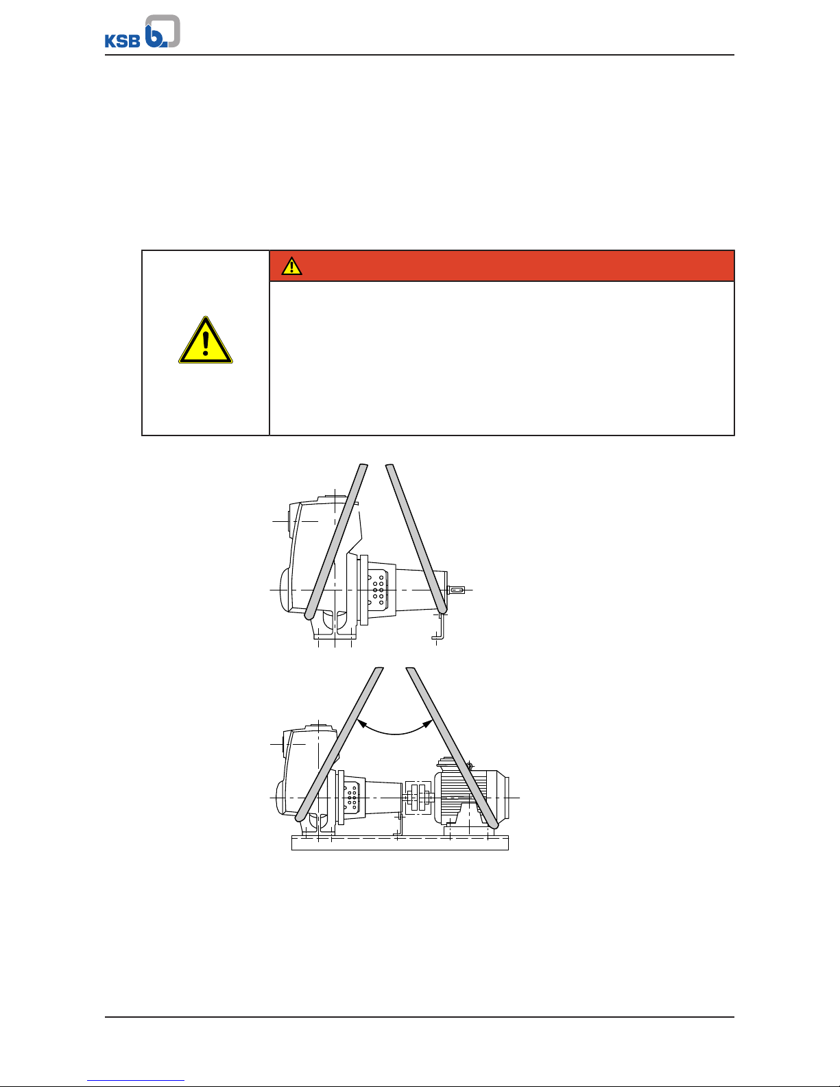
3.2 Transport
DANGER
The pump (set) could slip out of the suspension arrangement
Danger to life from falling parts!
▷ Always transport the pump (set) in the specified position.
▷ Never attach the suspension arrangement to the free shaft end or the motor
eyebolt.
▷ Give due attention to the weight data and the centre of gravity.
▷ Observe the applicable local health and safety regulations.
▷ Use suitable, permitted lifting accessories, e.g. self-tightening lifting tongs.
To transport the pump/pump set suspend it from the lifting tackle as shown.
Fig.1: Transporting the pump
max. 90 °
Fig.2: Transporting the complete pump set
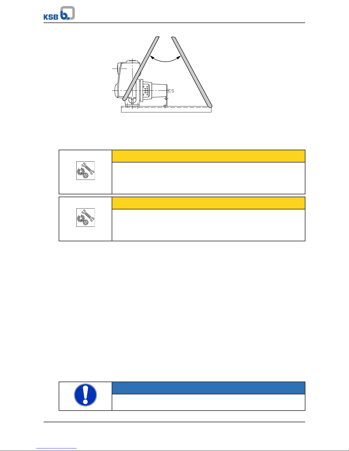
3 Transport/Temporary Storage/Disposal
15 of 76
Etaprime L
max. 90 °
Fig.3: Transporting the pump on the baseplate
3.3 Storage/preservation
If commissioning is to take place some time after delivery, we recommend that the
following measures be taken for pump (set) storage.
CAUTION
Damage during storage by humidity, dirt, or vermin
Corrosion/contamination of the pump (set)!
▷ For outdoor storage cover the packed or unpacked pump (set) and accessories
with waterproof material.
CAUTION
Wet, contaminated or damaged openings and connections
Leakage or damage to the pump!
▷ Clean and cover pump openings and connections as required prior to putting
the pump into storage.
Store the pump (set) in a dry, protected room where the atmospheric humidity is as
constant as possible.
Rotate the shaft by hand once a month, e.g. via the motor fan.
If properly stored indoors, the pump set is protected for a maximum of 12 months.
New pumps/pump sets are supplied by our factory duly prepared for storage.
For storing a pump (set) which has already been operated, the shutdown measures
must be adhered to. (ðSection6.3.1,Page40)
3.4 Return to supplier
1. Drain the pump as per operating instructions. (ðSection7.3,Page49)
2. Flush and clean the pump, particularly if it has been used for handling noxious,
explosive, hot or other hazardous fluids.
3. If the pump has handled fluids whose residues could lead to corrosion damage
in the presence of atmospheric humidity or could ignite upon contact with
oxygen also neutralise the pump and blow through with anhydrous inert gas to
ensure drying.
4. Always complete and enclose a certificate of decontamination when returning
the pump.
Indicate any safety measures and decontamination measures taken.
(ðSection11,Page71)
NOTE
If required, a blank certificate of decontamination can be downloaded from the
following web site: www.ksb.com/certificate_of_decontamination
3 Transport/Temporary Storage/Disposal
16 of 76
Etaprime L
3.5 Disposal
WARNING
Fluids handled, consumables and supplies which are hot and/or pose a health
hazard
Hazard to persons and the environment!
▷ Collect and properly dispose of flushing fluid and any fluid residues.
▷ Wear safety clothing and a protective mask if required.
▷ Observe all legal regulations on the disposal of fluids posing a health hazard.
1. Dismantle the pump (set).
Collect greases and other lubricants during dismantling.
2. Separate and sort the pump materials, e.g. by:
- Metals
- Plastics
- Electronic waste
- Greases and other lubricants
3. Dispose of materials in accordance with local regulations or in another
controlled manner.
4 Description of the Pump (Set)
17 of 76
Etaprime L
4 Description of the Pump (Set)
4.1 General description
▪ Self-priming pump
The pump is designed for handling clean or contaminated fluids in waste water
management, on construction sites, in agriculture, in the general or chemical
industry, in the petroleum, food processing and canning industry and for circulating
solvents and cleaning agents with a viscosity of up to 50mm²/s. A solids content of up
to 3% is permissible, but the fluid handled must not contain long fibres.
4.2 Designation
Example: ETPL080-080-200GCXI10D3
Table5: Designation key
Code Description
ETPL EtaprimeL type series
080 Nominal suction nozzle diameter [mm]
080 Nominal discharge nozzle diameter [mm]
200 Nominal impeller diameter [mm]
G Casing material, e.g. G=cast iron
C Impeller material if different from casing material, e.g.
C=stainless steel
X Additional code, e.g. X=special design
I Sealing system, e.g. I = single mechanical seal
10 Shaft seal, e.g. 10 = Q1Q1X4GG
D Scope of supply, e.g. D = pump with motor, baseplate,
coupling, coupling guard
3 Shaft unit, e.g. 3 = SU35
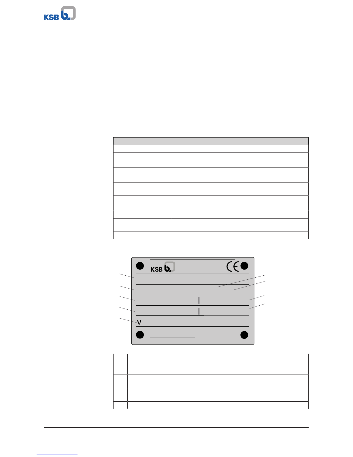
4.3 Name plate
ETPL080-080-200 GCXI10D3
9971234567 000100 / 01
Q 60 m3/h
H 32 m
n 2900 1/min 2016
KSB ITUR Spain, S.A.
Camino de Urteta S/N
20800 Zarautz
Mat-No. 01529956 PC-01
9
8
7
6
1
2
5
4
3
1 mm2/s
Fig.4: EtaprimeL name plate (example)
1 Type series, size and version 2 KSB order number
(ten digits)
3 Flow rate 4 Rotational speed
5 Kinematic viscosity of the fluid
handled
6 Order item number
(six digits)
7 Consecutive number
(two digits)
8 Head
9 Year of construction
4 Description of the Pump (Set)
18 of 76
Etaprime L
4.4 Design details
Design
▪ Volute casing pump
▪ Back pull-out design (from size 40-40-140)
▪ Horizontal installation
▪ Self-priming
▪ Single-stage
▪ Single-entry
Pump casing
▪ Radially split volute casing
▪ Volute casing with integrally cast pump feet (from pump size 40-40-140)
Impeller type
▪ Open multi-channel impeller
Bearings
▪ Floating bearings: deep groove ball bearings
Shaft seal
▪ The shaft is fitted with a replaceable shaft sleeve in the shaft seal area (from
pump size 40-40-140).
▪ Single and double mechanical seals to EN12756
Bearings used
Table6: Standard bearings
Version Bearing bracket Rolling element bearing
Pump end Drive end
Standard bearings
(grease lubrication)
SU17 3203C3 62032RS
SU25 6305 2Z C3 6305 2Z C3
SU35 6307 2Z C3 6307 2Z C3
Standard bearings
(oil lubrication)
SU17 - -
SU25 6305 C3 6305 C3
SU35 6307 C3 6307 C3
Lubrication:
▪ Grease lubrication
▪ Oil lubrication
Drive
▪ KSB IEC frame standardised IE3 motor (from 0.75 kW)
▪ 230/400 V up to 2.2 kW and 400/690 V from 3 kW
▪ Winding 60Hz, 3~ 440-480V ≥ 2.41 hp (1.80 kW)
▪ Type of construction B3
▪ IP55 enclosure
▪ Thermal class F with temperature sensor, 3 PTC thermistors
▪ Duty cycle: continuous duty S1
4 Description of the Pump (Set)
19 of 76
Etaprime L
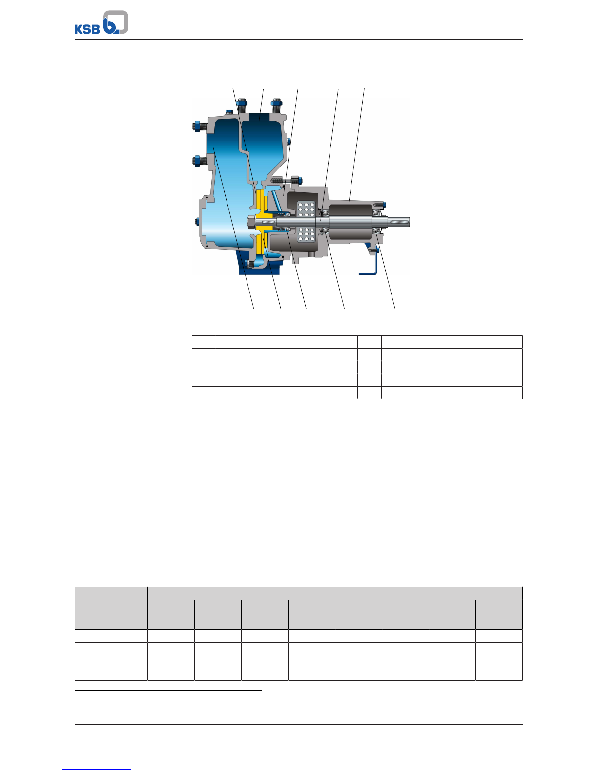
4.5 Design and function
51 2 3 4
6 7 8 9 10
Fig.5: Sectional drawing
1 Clearance gap 2 Discharge nozzle
3 Casing cover 4 Shaft
5 Bearing bracket 6 Suction nozzle
7 Impeller 8 Shaft seal
9 Rolling element bearing, pump end 10 Rolling element bearing, motor end
Design
The pump is designed with an axial fluid inlet and a radial outlet. The pump section
runs in its own bearings and is connected to the motor by a shaft coupling.
Function
The fluid enters the pump axially via the suction nozzle (6) and is accelerated
outward by the rotating impeller (7). In the flow passage of the pump casing the
kinetic energy of the fluid is converted into pressure energy. The fluid is pumped to
the discharge nozzle (2), where it leaves the pump. The clearance gap (1) prevents
any fluid from flowing back from the casing to the suction nozzle. At the rear side of
the impeller, the shaft (4) enters the hydraulic system via the casing cover (3). The
shaft passage through the casing cover is sealed to atmosphere with a dynamic shaft
seal (8). The shaft runs in rolling element bearings (9 and 10), which are supported by
a bearing bracket (5) linked with the pump casing and/or casing cover. The filled
pump is self-priming.
Sealing
The pump is sealed by a standardised mechanical seal.
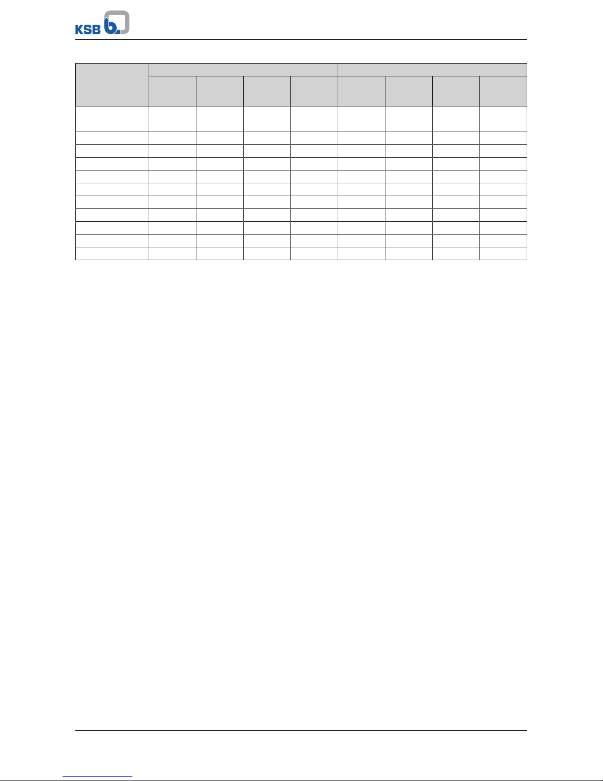
4.6 Noise characteristics
Table7: Surface sound pressure level L
pA
2)
Rated power
input
P
N
[kW]
Pump Pump set
1450rpm
[dB]
1750rpm
[dB]
2900rpm
[dB]
3500rpm
[dB]
1450rpm
[dB]
1750rpm
[dB]
2900rpm
[dB]
3500rpm
[dB]
0,37 59 60 - - 60 61 - -
0,55 60 61 70 - 61 62 73 -
0,75 - - 71 74 - - 74 77
1,1 - - 72 75 - - 75 78
2) Spatial average; as per ISO3744 and EN12639; valid for pump operation in the Q/Qopt=0.8-1.1 range and for non-
cavitating operation. If noise levels are to be guaranteed: Add +3dB for measuring and constructional tolerance.
4 Description of the Pump (Set)
20 of 76
Etaprime L
Rated power
input
P
N
[kW]
Pump Pump set
1450rpm
[dB]
1750rpm
[dB]
2900rpm
[dB]
3500rpm
[dB]
1450rpm
[dB]
1750rpm
[dB]
2900rpm
[dB]
3500rpm
[dB]
1,5 62 63 73 76 63 64 76 79
2,2 66 67 74 77 67 68 77 80
3 66 67 75 - 67 68 78 -
4 67 68 75 78 68 69 78 81
5,5 70 71 76 79 71 72 79 82
7,5 70 71 78 81 71 72 81 84
11 72 73 78 81 73 74 81 84
15 - - 79 82 - - 82 85
18,5 - - 79 82 - - 82 85
22 - - 80 83 - - 83 86
30 - - 80 83 - - 83 86
37 - - 83 86 - - 86 89
4.7 Dimensions and weights
For dimensions and weights please refer to the general arrangement drawing/outline
drawing of the pump/pump set.
4.8 Scope of supply
Depending on the model, the following items are included in the scope of supply:
▪ Pump
▪ Baseplate
▪ Coupling
▪ Coupling guard
▪ Drive
5 Installation at Site
21 of 76
Etaprime L
5 Installation at Site
5.1 Safety regulations
DANGER
Improper installation in potentially explosive atmospheres
Explosion hazard!
Damage to the pump set!
▷ Comply with the applicable local explosion protection regulations.
▷ Observe the information in the data sheet and on the name plates of pump and
motor.
DANGER
Risk of ignition by frictional sparks
Risk of explosion!
▷ Choose a coupling guard material that is non-sparking in the event of
mechanical contact (see DIN EN 13463-1).
▷ If any coupling parts are made of aluminium, a brass coupling guard must be
used.
5.2 Checks to be carried out prior to installation
Place of installation
WARNING
Installation on mounting surface which is unsecured and cannot support the load
Personal injury and damage to property!
▷ Use a concrete of compressive strength class C12/15 which meets the
requirements of exposure class XC1 to EN206-1.
▷ The mounting surface must have set and must be completely horizontal and
even.
▷ Observe the weights indicated.
1. Check the structural requirements.
All structural work required must have been prepared in accordance with the
dimensions stated in the outline drawing/general arrangement drawing.
5.3 Installing the pump set
Always install the pump set in a horizontal position.
DANGER
Excessive temperatures due to improper installation
Explosion hazard!
▷ Install the pump in a horizontal position to ensure self-venting of the pump.
5 Installation at Site
22 of 76
Etaprime L
5.3.1 Installation on the foundation
L
1
32
Fig.6: Fitting the shims
L Bolt-to-bolt distance 1 Shim
2 Shim if (L) > 800mm 3 Foundation bolt
ü The foundation has the required strength and characteristics.
ü The foundation has been prepared in accordance with the dimensions given in
the outline drawing/general arrangement drawing.
1. Position the pump set on the foundation and level it with the help of a spirit
level placed on the shaft and discharge nozzle.
Permissible deviation: 0.2mm/m
2. Use shims (1) for height compensation, if necessary.
Always fit shims, if any, immediately to the left and right of the foundation
bolts (3) between the baseplate/foundation frame and the foundation.
For a bolt-to-bolt distance (L) >800mm fit additional shims (2) halfway between
the bolt holes.
All shims must lie perfectly flush.
3. Insert the foundation bolts (3) into the holes provided.
4. Use concrete to set the foundation bolts (3) into the foundation.
5. Wait until the concrete has set firmly, then level the baseplate.
6. Tighten the foundation bolts (3) evenly and firmly.
NOTE
For baseplates more than 400 mm wide grouting the baseplate with low-shrinkage
concrete is recommended.
NOTE
For baseplates made of grey cast iron grouting the baseplate with low-shrinkage
concrete is recommended.
NOTE
For low-noise operation contact the manufacturer to check whether the pump set
can be installed on anti-vibration mounts.
NOTE
Expansion joints can be fitted between the pump and the suction/discharge line.
5 Installation at Site
23 of 76
Etaprime L
5.3.2 Installation without foundation
4
1
2
3
Fig.7: Adjusting the levelling elements
1, 3 Locknut 2 Adjusting nut
4 Machine mount
ü The installation surface has the required strength and characteristics.
1. Position the pump set on the machine mounts (4) and align it with the help of a
spirit level (on the shaft/discharge nozzle).
2. To adjust any differences in height, loosen the locknuts (1, 3) of the machine
mounts (4).
3. Turn the adjusting nut (2) until any differences in height have been
compensated.
4. Re-tighten the locknuts (1, 3) at the machine mounts (4).
5.4 Piping
5.4.1 Connecting the piping
DANGER
Impermissible loads acting on the pump nozzles
Danger to life from escaping hot, toxic, corrosive or flammable fluids!
▷ Do not use the pump as an anchorage point for the piping.
▷ Anchor the pipes in close proximity to the pump and connect them properly
without transmitting any stresses or strains.
▷ Observe the permissible forces and moments at the pump nozzles.
(ðSection5.4.2,Page25)
▷ Take appropriate measures to compensate for thermal expansion of the piping.
CAUTION
Incorrect earthing during welding work at the piping
Destruction of rolling element bearings (pitting effect)!
▷ Never earth the electric welding equipment on the pump or baseplate.
▷ Prevent current flowing through the rolling element bearings.
NOTE
Installing check and shut-off elements in the system is recommended, depending on
the type of plant and pump. However, such elements must not obstruct proper
drainage or hinder disassembly of the pump.
 Loading...