

KSB Etanorm-RX Operating Manual
Sprinkler Pump
Etanorm-RX
Installation/Operating Manual

Legal information/Copyright
Installation/Operating Manual Etanorm-RX
Original operating manual
All rights reserved. The contents provided herein must neither be distributed, copied, reproduced,
edited or processed for any other purpose, nor otherwise transmitted, published or made available to a
third party without the manufacturer's express written consent.
Subject to technical modification without prior notice.
© KSB SE & Co. KGaA, Frankenthal 14/12/2017

Contents
Contents
Glossary .................................................................................................................................................. 5
1 General.................................................................................................................................................... 6
1.1 Principles ...........................................................................................................................................................6
1.2 Installation of partly completed machinery....................................................................................................6
1.3 Target group.....................................................................................................................................................6
1.4 Other applicable documents............................................................................................................................6
1.5 Symbols .............................................................................................................................................................6
2 Safety...................................................................................................................................................... 8
2.1 Key to safety symbols/markings.......................................................................................................................8
2.2 General..............................................................................................................................................................8
2.3 Intended use .....................................................................................................................................................8
2.4 Personnel qualification and training...............................................................................................................9
2.5 Consequences and risks caused by non-compliance with this manual .........................................................9
2.6 Safety awareness ..............................................................................................................................................9
2.7 Safety information for the operator/user.......................................................................................................9
2.8 Safety information for maintenance, inspection and installation work.....................................................10
2.9 Unauthorised modes of operation................................................................................................................10
3 Transport/Temporary Storage/Disposal............................................................................................. 11
3.1 Checking the condition upon delivery..........................................................................................................11
3.2 Transport.........................................................................................................................................................11
3.3 Storage/preservation......................................................................................................................................12
3.4 Return to supplier...........................................................................................................................................12
3.5 Disposal ...........................................................................................................................................................13
4 Description of the Pump (Set)............................................................................................................. 14
4.1 General description ........................................................................................................................................14
4.2 Designation.....................................................................................................................................................14
4.3 Name plate......................................................................................................................................................14
4.4 Design details..................................................................................................................................................14
4.5 Design and function.......................................................................................................................................15
4.6 Noise characteristics .......................................................................................................................................16
4.7 Scope of supply...............................................................................................................................................16
4.8 Dimensions and weights ................................................................................................................................16
5 Installation at Site................................................................................................................................ 17
5.1 Safety regulations...........................................................................................................................................17
5.2 Checks to be carried out prior to installation...............................................................................................17
5.3 Installing the pump set ..................................................................................................................................17
5.3.1 Installation on the foundation..........................................................................................................17
5.4 Piping ..............................................................................................................................................................18
5.4.1 Connecting the piping.......................................................................................................................18
5.4.2 Permissible forces and moments at the pump nozzles....................................................................20
5.4.3 Auxiliary connections.........................................................................................................................20
5.5 Enclosure/insulation .......................................................................................................................................21
5.6 Checking the coupling alignment .................................................................................................................21
5.7 Aligning the pump and motor ......................................................................................................................22
5.7.1 Motors with levelling screw ..............................................................................................................22
5.7.2 Motors without levelling screw ........................................................................................................23
5.8 Electrical connection ......................................................................................................................................23
5.9 Checking the direction of rotation................................................................................................................24
6 Commissioning/Start-up/Shutdown................................................................................................... 25
6.1 Commissioning/Start-up.................................................................................................................................25
6.1.1 Prerequisites for commissioning/start-up ......................................................................................... 25
6.1.2 Priming and venting the pump.........................................................................................................25
Etanorm-RX
3 of 56

Contents
6.1.3 Final check ..........................................................................................................................................25
6.1.4 Start-up for testing ...........................................................................................................................25
6.1.5 Checking the shaft seal......................................................................................................................25
6.1.6 Switching the pump set off after testing ......................................................................................... 26
6.2 Operating limits..............................................................................................................................................26
6.2.1 Ambient temperature........................................................................................................................26
6.2.2 Frequency of starts.............................................................................................................................27
6.2.3 Fluid handled .....................................................................................................................................27
6.3 Shutdown/storage/preservation ....................................................................................................................28
6.3.1 Measures to be taken for shutdown ................................................................................................28
6.4 Returning to service .......................................................................................................................................28
7 Servicing/Maintenance........................................................................................................................ 29
7.1 Safety regulations...........................................................................................................................................29
7.2 Maintenance/inspection.................................................................................................................................29
7.2.1 Supervision of operation ................................................................................................................... 29
7.2.2 Inspection work..................................................................................................................................30
7.2.3 Lubrication and lubricant change of rolling element bearings ...................................................... 31
7.3 Drainage/cleaning ..........................................................................................................................................32
7.4 Dismantling the pump set..............................................................................................................................32
7.4.1 General information/Safety regulations...........................................................................................32
7.4.2 Preparing the pump set.....................................................................................................................33
7.4.3 Removing the motor..........................................................................................................................33
7.4.4 Removing the back pull-out unit ...................................................................................................... 33
7.4.5 Removing the impeller ......................................................................................................................34
7.4.6 Removing the shaft seal ....................................................................................................................34
7.4.7 Dismantling the bearings ..................................................................................................................36
7.5 Reassembling the pump set...........................................................................................................................36
7.5.1 General information/Safety regulations...........................................................................................36
7.5.2 Fitting the bearings ...........................................................................................................................37
7.5.3 Fitting the shaft seal ..........................................................................................................................38
7.5.4 Fitting the impeller ............................................................................................................................42
7.5.5 Installing the back pull-out unit .......................................................................................................42
7.5.6 Mounting the motor .........................................................................................................................42
7.6 Tightening torques.........................................................................................................................................43
7.6.1 Tightening torques for the pump.....................................................................................................43
7.6.2 Tightening torques for the pump set ............................................................................................... 43
7.7 Spare parts stock.............................................................................................................................................44
7.7.1 Ordering spare parts..........................................................................................................................44
7.7.2 Recommended spare parts stock for 2 years' operation to DIN 24296 ..........................................44
8 Trouble-shooting.................................................................................................................................. 46
9 Related Documents.............................................................................................................................. 48
9.1 General assembly drawing with list of components ....................................................................................48
9.1.1 Etanorm-RX ........................................................................................................................................48
10 EC Declaration of Conformity ............................................................................................................. 49
11 Certificate of Decontamination........................................................................................................... 51
Index ..................................................................................................................................................... 52
4 of 56
Etanorm-RX

Glossary
Glossary
Back pull-out design
The complete back pull-out unit can be pulled out
without having to remove the pump casing from
the piping.
Back pull-out unit
Pump without pump casing; partly completed
machinery
Certificate of decontamination
A certificate of decontamination is enclosed by the
customer when returning the product to the
manufacturer to certify that the product has been
properly drained to eliminate any environmental
and health hazards arising from components in
contact with the fluid handled.
Discharge line
The line which is connected to the discharge
nozzle
Hydraulic system
The part of the pump in which the kinetic energy
is converted into pressure energy
Pump
Machine without drive, additional components or
accessories
Pump set
Complete pump set consisting of pump, drive,
additional components and accessories
Suction lift line/suction head line
The line which is connected to the suction nozzle
Etanorm-RX
5 of 56
1 General
1 General
1.1 Principles
This operating manual is supplied as an integral part of the type series and variants
indicated on the front cover. The manual describes the proper and safe use of this
equipment in all phases of operation.
The name plate indicates the type series and size, the main operating data, the order
number and the order item number. The order number and order item number
uniquely identify the pump (set) and serve as identification for all further business
processes.
In the event of damage, immediately contact your nearest KSB service centre to
maintain the right to claim under warranty.
Noise characteristics see (ðSection4.6,Page16)
1.2 Installation of partly completed machinery
To install partly completed machinery supplied by KSB, refer to the sub-sections
under Servicing/Maintenance.
1.3 Target group
This manual is aimed at the target group of trained and qualified specialist technical
personnel.
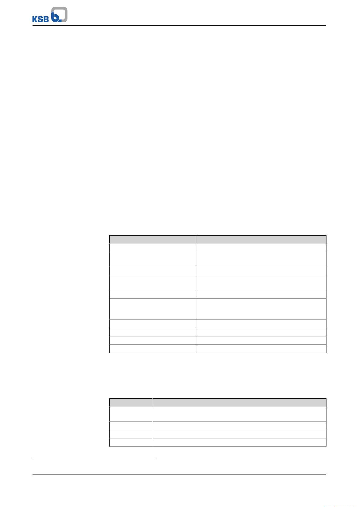
1.4 Other applicable documents
Table1: Overview of other applicable documents
Document Contents
Data sheet Description of the technical data of the pump (set)
General arrangement drawing/
outline drawing
Description of mating and installation dimensions
for the pump (set), weights
Drawing of auxiliary connections Description of auxiliary connections
Hydraulic characteristic curve Characteristic curves showing head, NPSH
required, efficiency and power input
General assembly drawing
1)
Sectional drawing of the pump
Sub-supplier product literature1)Operating manuals and other product literature
describing accessories and integrated machinery
components
Spare parts lists
Piping layout
List of components
1)
1)
1)
Description of spare parts
Description of auxiliary piping
Description of all pump components
Drawing for assembly Sectional drawing of the installed shaft seal
For accessories and/or integrated machinery components observe the relevant
manufacturer's product literature.
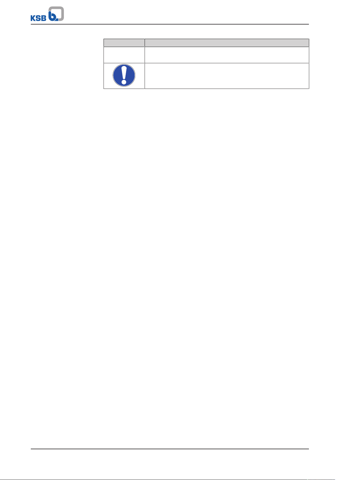
1.5 Symbols
Table2: Symbols used in this manual
Symbol Description
✓ Conditions which need to be fulfilled before proceeding with the
step-by-step instructions
⊳ Safety instructions
⇨ Result of an action
⇨ Cross-references
1) If agreed upon in scope of supply
6 of 56
Etanorm-RX
1 General
Symbol Description
1.
2.
Step-by-step instructions
Note
Recommendations and important information on how to handle
the product
Etanorm-RX
7 of 56
2 Safety
!
DANGER
!
DANGER
!
WARNING
CAUTION
2 Safety
All the information contained in this section refers to hazardous situations.
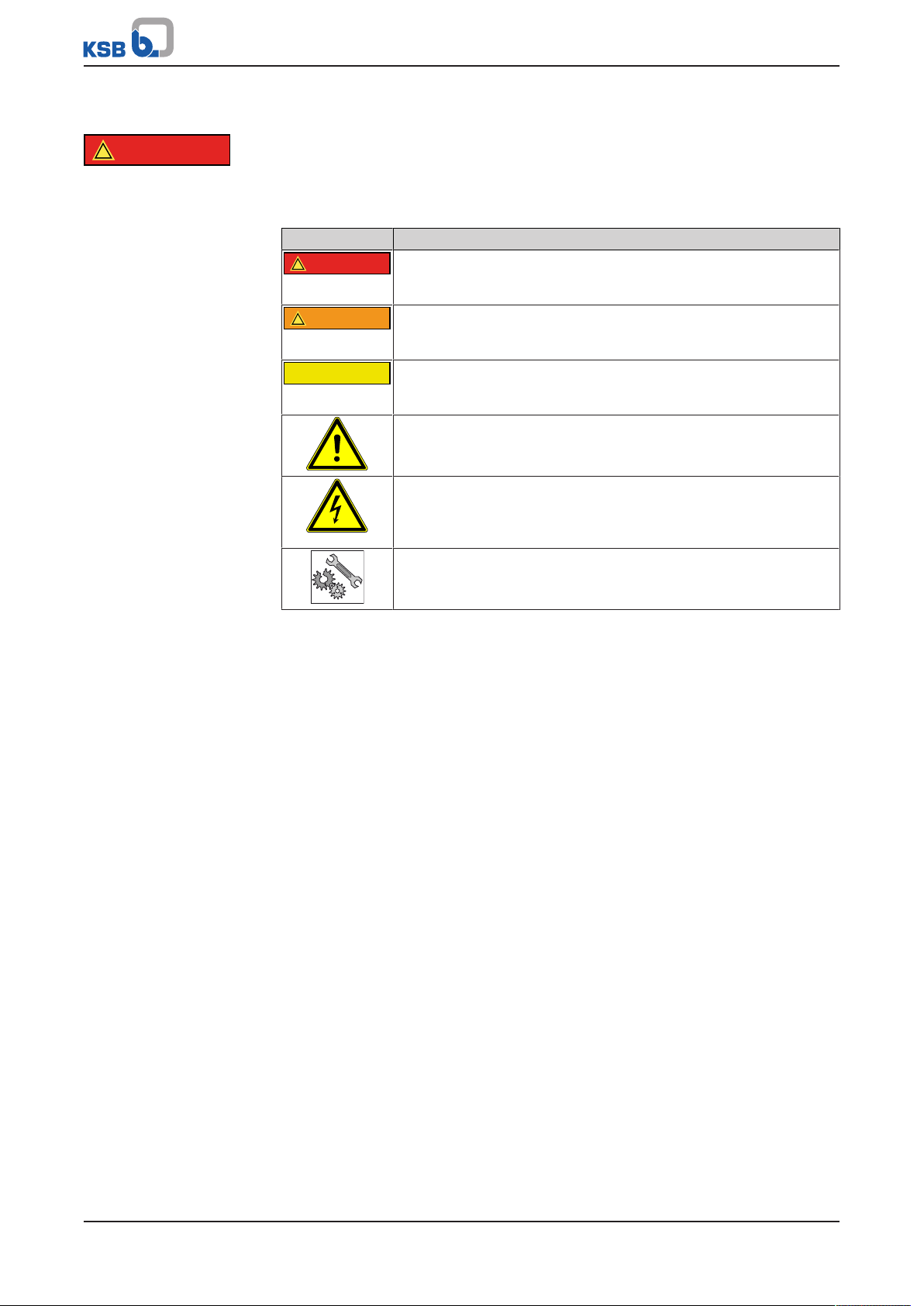
2.1 Key to safety symbols/markings
Table3: Definition of safety symbols/markings
Symbol Description
DANGER
This signal word indicates a high-risk hazard which, if not avoided,
will result in death or serious injury.
WARNING
This signal word indicates a medium-risk hazard which, if not
avoided, could result in death or serious injury.
CAUTION
This signal word indicates a hazard which, if not avoided, could
result in damage to the machine and its functions.
General hazard
In conjunction with one of the signal words this symbol indicates a
hazard which will or could result in death or serious injury.
Electrical hazard
In conjunction with one of the signal words this symbol indicates a
hazard involving electrical voltage and identifies information about
protection against electrical voltage.
Machine damage
In conjunction with the signal word CAUTION this symbol indicates
a hazard for the machine and its functions.
2.2 General
This manual contains general installation, operating and maintenance instructions
that must be observed to ensure safe pump operation and prevent personal injury
and damage to property.
The safety information in all sections of this manual must be complied with.
This manual must be read and completely understood by the specialist personnel/
operators responsible prior to installation and commissioning.
The contents of this manual must be available to the specialist personnel at the site
at all times.
Information attached directly to the pump must always be complied with and be
kept in a perfectly legible condition at all times. This applies to, for example:
▪ Arrow indicating the direction of rotation
▪ Markings for connections
▪ Name plate
The operator is responsible for ensuring compliance with all local regulations not
taken into account in this manual.
2.3 Intended use
The pump (set) must only be operated within the operating limits described in the
other applicable documents. (ðSection1.4,Page6)
▪ Only operate pumps/pump sets which are in perfect technical condition.
▪ Do not operate the pump (set) in partially assembled condition.
▪ Only use the pump to handle the fluids described in the data sheet or product
literature of the pump model.
▪ Never operate the pump without the fluid handled.
▪ Observe the minimum flow rates indicated in the data sheet or product literature
(to prevent overheating, bearing damage, etc).
8 of 56
Etanorm-RX

2 Safety
▪ Observe the maximum flow rates indicated in the data sheet or product
literature (to prevent overheating, mechanical seal damage, cavitation damage,
bearing damage, etc).
▪ Do not throttle the flow rate on the suction side of the pump (to prevent
cavitation damage).
▪ Consult the manufacturer about any use or mode of operation not described in
the data sheet or product literature.
Prevention of foreseeable misuse
▪ Never open discharge-side shut-off elements further than permitted.
– The maximum flow rate specified in the data sheet or product literature
would be exceeded.
– Risk of cavitation damage
▪ Never exceed the permissible operating limits specified in the data sheet or
product literature regarding pressure, temperature, etc.
▪ Observe all safety information and instructions in this manual.
2.4 Personnel qualification and training
All personnel involved must be fully qualified to transport, install, operate, maintain
and inspect the machinery this manual refers to.
The responsibilities, competence and supervision of all personnel involved in
transport, installation, operation, maintenance and inspection must be clearly
defined by the operator.
Deficits in knowledge must be rectified by means of training and instruction
provided by sufficiently trained specialist personnel. If required, the operator can
commission the manufacturer/supplier to train the personnel.
Training on the pump (set) must always be supervised by technical specialist
personnel.
2.5 Consequences and risks caused by non-compliance with this manual
▪ Non-compliance with this operating manual will lead to forfeiture of warranty
cover and of any and all rights to claims for damages.
▪ Non-compliance can, for example, have the following consequences:
– Hazards to persons due to electrical, thermal, mechanical and chemical
effects and explosions
– Failure of important product functions
– Failure of prescribed maintenance and servicing practices
– Hazard to the environment due to leakage of hazardous substances
2.6 Safety awareness
In addition to the safety information contained in this manual and the intended use,
the following safety regulations shall be complied with:
▪ Accident prevention, health and safety regulations
▪ Explosion protection regulations
▪ Safety regulations for handling hazardous substances
▪ Applicable standards and laws
2.7 Safety information for the operator/user
▪ The operator shall fit contact guards for hot, cold and moving parts and check
that the guards function properly.
▪ Do not remove any contact guards during operation.
▪ Provide the personnel with protective equipment and make sure it is used.
Etanorm-RX
9 of 56

2 Safety
▪ Contain leakages (e.g. at the shaft seal) of hazardous fluids handled (e.g.
explosive, toxic, hot) so as to avoid any danger to persons and the environment.
Adhere to all relevant laws.
▪ Eliminate all electrical hazards. (In this respect refer to the applicable national
safety regulations and/or regulations issued by the local energy supply
companies.)
▪ If shutting down the pump does not increase potential risk, fit an emergency-
stop control device in the immediate vicinity of the pump (set) during pump set
installation.
2.8 Safety information for maintenance, inspection and installation work
▪ Modifications or alterations of the pump are only permitted with the
manufacturer's prior consent.
▪ Use only original spare parts or parts authorised by the manufacturer. The use of
other parts can invalidate any liability of the manufacturer for resulting damage.
▪ The operator ensures that all maintenance, inspection and installation work is
performed by authorised, qualified specialist personnel who are thoroughly
familiar with the manual.
▪ Only carry out work on the pump (set) during standstill of the pump.
▪ The pump casing must have cooled down to ambient temperature.
▪ Pump pressure must have been released and the pump must have been drained.
▪ When taking the pump set out of service always adhere to the procedure
described in the manual. (ðSection6.3,Page28)
▪ Decontaminate pumps which handle fluids posing a health hazard.
(ðSection7.3,Page32)
▪ As soon as the work has been completed, re-install and/or re-activate any safety-
relevant and protective devices. Before returning the product to service, observe
all instructions on commissioning. (ðSection6.1,Page25)
2.9 Unauthorised modes of operation
Never operate the pump (set) outside the limits stated in the data sheet and in this
manual.
The warranty relating to the operating reliability and safety of the supplied pump
(set) is only valid if the equipment is used in accordance with its intended use.
(ðSection2.3,Page8)
10 of 56
Etanorm-RX
3 Transport/Temporary Storage/Disposal
≤ 90 °
3 Transport/Temporary Storage/Disposal
3.1 Checking the condition upon delivery
1. On transfer of goods, check each packaging unit for damage.
2. In the event of in-transit damage, assess the exact damage, document it and
notify KSB or the supplying dealer (as applicable) and the insurer about the
damage in writing immediately.
3.2 Transport
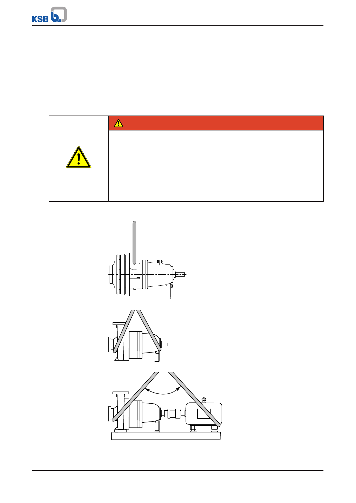
DANGER
The pump (set) could slip out of the suspension arrangement
Danger to life from falling parts!
▷ Always transport the pump (set) in the specified position.
▷ Never attach the suspension arrangement to the free shaft end or the motor
eyebolt.
▷ Give due attention to the weight data and the centre of gravity.
▷ Observe the applicable local health and safety regulations.
▷ Use suitable, permitted lifting accessories, e.g. self-tightening lifting tongs.
To transport the pump/pump set or back pull-out unit suspend it from the lifting tackle
as shown below.
Fig.1: Transporting the back pull-out unit
Fig.2: Transporting the pump
Fig.3: Transporting the complete pump set
Etanorm-RX
11 of 56
3 Transport/Temporary Storage/Disposal
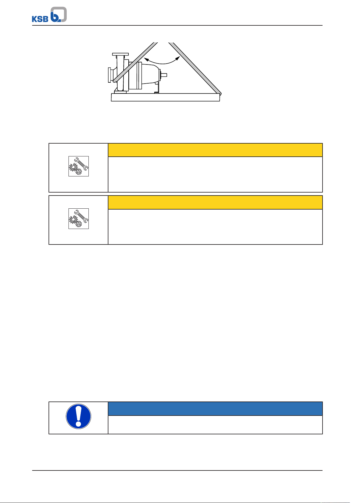
≤ 90 °
Fig.4: Transporting the pump on the baseplate
3.3 Storage/preservation
If commissioning is to take place some time after delivery, we recommend that the
following measures be taken for pump (set) storage.
CAUTION
Damage during storage due to humidity, dirt, or vermin
Corrosion/contamination of the pump (set)!
▷ For outdoor storage cover the packed or unpacked pump (set) and accessories
with waterproof material.
CAUTION
Wet, contaminated or damaged openings and connections
Leakage or damage to the pump set!
▷ Only remove caps/covers from the openings of the pump set at the time of
installation.
Store the pump (set) in a dry, protected room where the atmospheric humidity is as
constant as possible.
Rotate the shaft by hand once a month, e.g. via the motor fan.
If properly stored indoors, the pump set is protected for a maximum of 12 months.
New pumps/pump sets are supplied by our factory duly prepared for storage.
For storing a pump (set) which has already been operated, observe the instructions
in (ðSection6.3.1,Page28) .
3.4 Return to supplier
1. Drain the pump as per operating instructions. (ðSection7.3,Page32)
2. Always flush and clean the pump, particularly if it has been used for handling
noxious, explosive, hot or other hazardous fluids.
3. If the pump set has handled fluids whose residues could lead to corrosion
damage in the presence of atmospheric humidity or could ignite upon contact
with oxygen, the pump set must also be neutralised, and anhydrous inert gas
must be blown through the pump to ensure drying.
4. Always complete and enclose a certificate of decontamination when returning
the pump (set).
Always indicate any safety and decontamination measures taken.
(ðSection11,Page51)
12 of 56
NOTE
If required, a blank certificate of decontamination can be downloaded from the
following web site: www.ksb.com/certificate_of_decontamination
Etanorm-RX
3 Transport/Temporary Storage/Disposal
3.5 Disposal
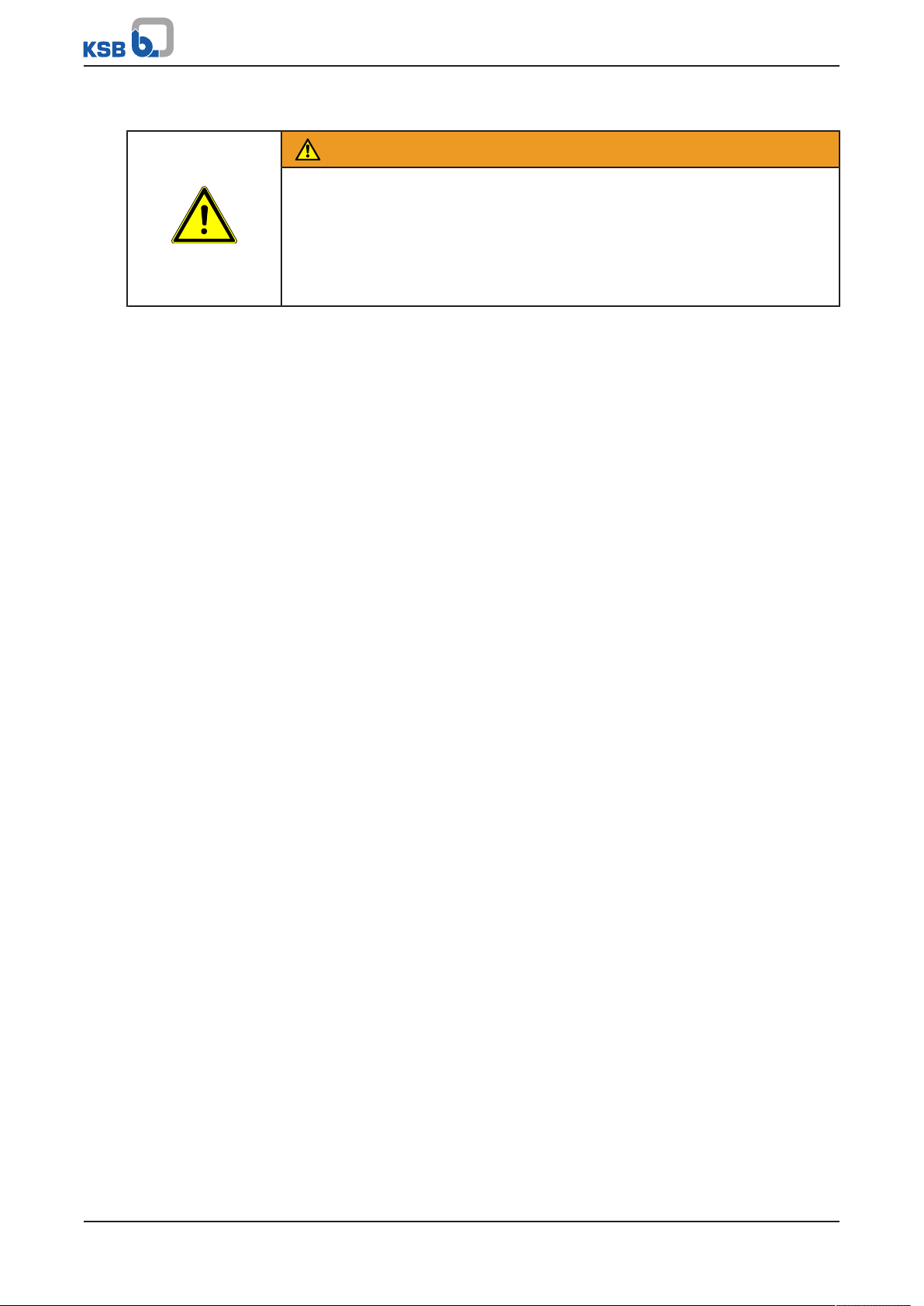
WARNING
Fluids, consumables and supplies which are hot and/or pose a health hazard
Hazard to persons and the environment!
▷ Collect and properly dispose of flushing fluid and any residues of the fluid
handled.
▷ Wear safety clothing and a protective mask if required.
▷ Observe all legal regulations on the disposal of fluids posing a health hazard.
1. Dismantle the pump (set).
Collect greases and other lubricants during dismantling.
2. Separate and sort the pump materials, e.g. by:
- Metals
- Plastics
- Electronic waste
- Greases and other lubricants
3. Dispose of materials in accordance with local regulations or in another
controlled manner.
Etanorm-RX
13 of 56
4 Description of the Pump (Set)
Sprinklerpumpe Typ
Fabr.-Nr.
VdS-Anerk.-Nr.
Q zul.
n
N
Laufraddurchmesser
max. IA Direkt
Umschaltstrom Y
l/min
1/min
H
P
P
N
M
kW
m
mm
A
A
Mat-No. 01493872 ZN 3814 - 36 DE
ETANORM RX 200-500
9971581385 000100 01
P 4830408
11050
1470
510
10 bar
85
250
Jahr
2013
Johann-Klein-Straße 9
Deutschland
67227 Frankenthal
KSB SE & Co. KGaA
8
7
6
5
4
3
2
1
9
10
11
12
4 Description of the Pump (Set)
4.1 General description
▪ Volute casing pump for sprinkler installations to VdS CEA 4001
4.2 Designation
Example: Etanorm-RX 200-500
Table4: Key to the designation
Code Description
Etanorm Type series
RX Sprinkler version
200 Nominal discharge nozzle diameter [mm]
500 Nominal impeller diameter [mm]
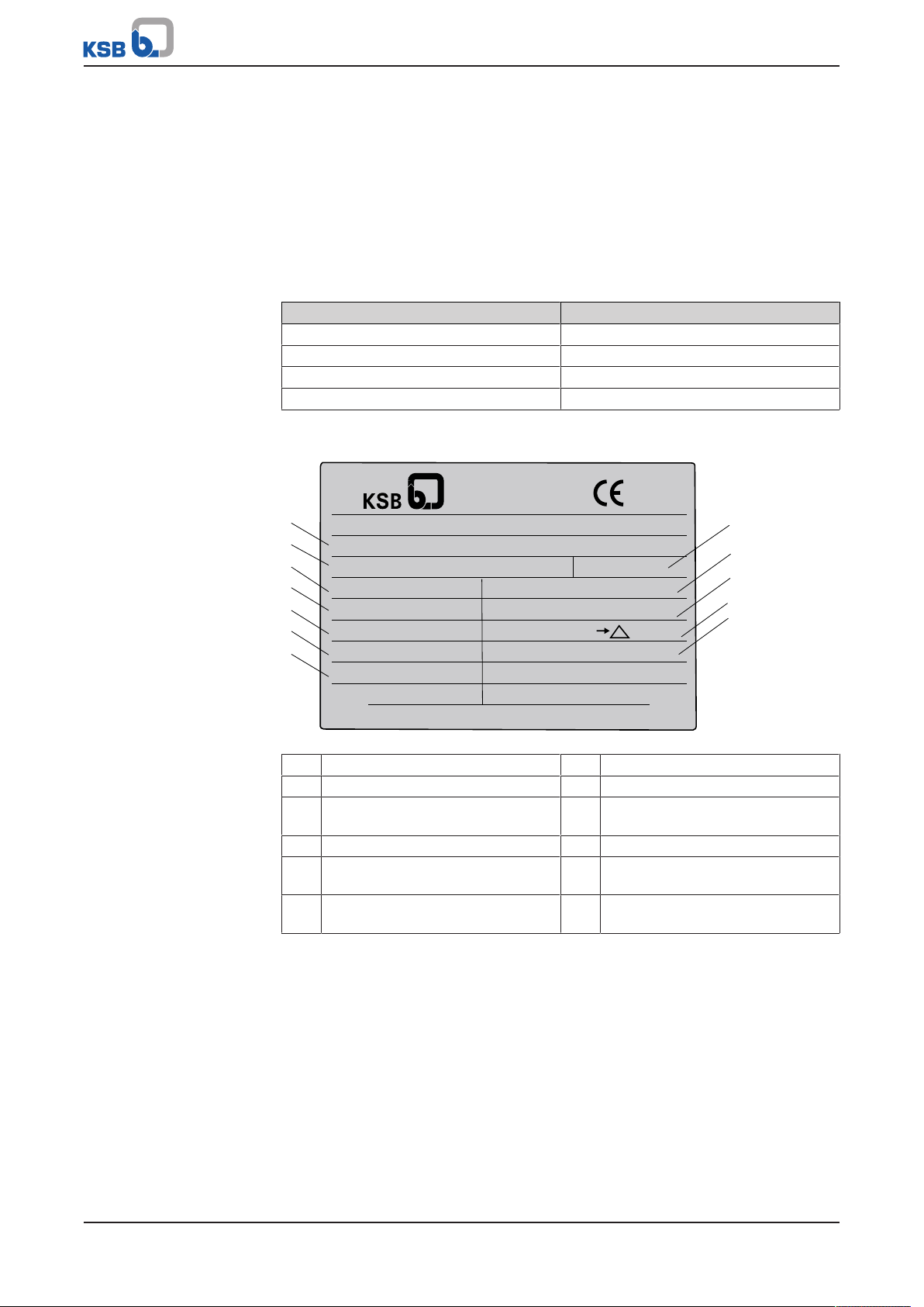
4.3 Name plate
Fig.5: Name plate (example)
1 Type series, size 2 KSB order and order item number
3 VdS-approved flow rate 4 VdS-approved head
5 Required motor rating at 15 m
NPSH
7 Permissible nominal pressure 8 Year of construction
9 Impeller diameter [mm] 10 Maximum starting current (only
11 Switching current (only relevant for
submersible pumps)
6 Rated speed
relevant for submersible pumps)
12 VdS approval number
4.4 Design details
Design
▪ Volute casing pump
14 of 56
▪ Horizontal installation
▪ Back pull-out design
▪ Single-stage
▪ Shaft equipped with a replaceable shaft sleeve in the shaft seal area
Etanorm-RX
4 Description of the Pump (Set)
1 2 3 4 5
6 7 8 9 10
Pump casing
▪ Single or double volute, depending on the pump size
▪ Radially split volute casing
▪ Volute casing with integrally cast pump feet
▪ Replaceable casing wear rings
Impeller type
▪ Closed radial impeller with multiply curved vanes
Shaft seal
▪ Gland packing
▪ KSB cartridge seal
▪ Standardised mechanical seal to EN 12756
Bearings
▪ Grease-packed deep groove ball bearings
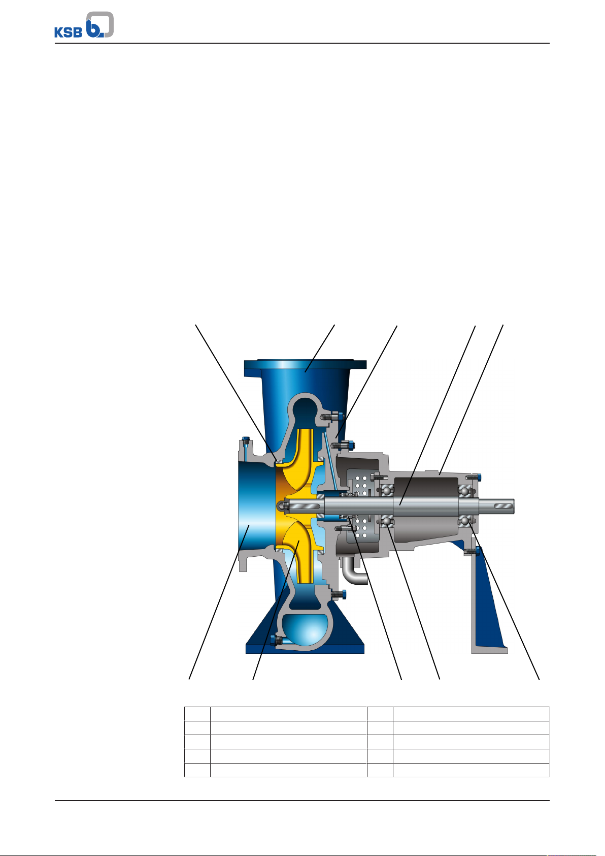
4.5 Design and function
Fig.6: Sectional drawing
1 Clearance gap 2 Discharge nozzle
3 Casing cover 4 Drive shaft
5 Bearing bracket 6 Suction nozzle
7 Impeller 8 Shaft seal
9 Rolling element bearing, pump end 10 Rolling element bearing, drive end
Etanorm-RX
15 of 56
4 Description of the Pump (Set)
Design
Function
Sealing
The pump is designed with an axial fluid inlet and a radial or tangential outlet. The
hydraulic system runs in its own bearings and is connected to the motor by a shaft
coupling.
The fluid enters the pump axially via the suction nozzle (6) and is accelerated
outward by the rotating impeller (7). In the flow passage of the pump casing the
kinetic energy of the fluid is converted into pressure energy. The fluid is pumped to
the discharge nozzle (2), where it leaves the pump. The clearance gap (1) prevents
any fluid from flowing back from the casing to the suction nozzle. At the rear side of
the impeller, the shaft (4) enters the casing via the casing cover (3). The shaft passage
through the cover is sealed to atmosphere with a shaft seal (8). The shaft runs in
rolling element bearings (9 and 10), which are supported by a bearing bracket (5)
linked with the pump casing and/or casing cover.
The pump is sealed by a shaft seal (KSB cartridge seal or gland packing).
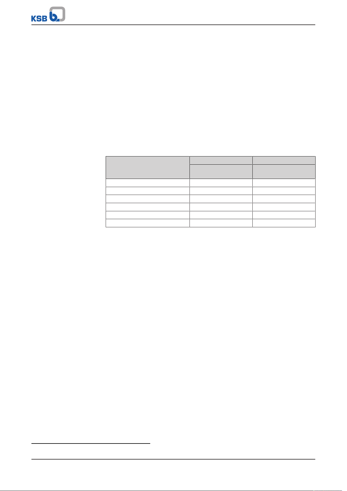
4.6 Noise characteristics
Table5: Surface sound pressure level L
Rated power input PN [kW] Pump Pump set
90 74 77
110 75 78
132 75 78
160 76 79
200 77 80
250 78 81
2)
pA
1450 rpm
[dB]
1450 rpm
[dB]
4.7 Scope of supply
Depending on the model, the following items are included in the scope of supply:
▪ Pump
▪ Baseplate
▪ Coupling
▪ Coupling guard
▪ Motor
4.8 Dimensions and weights
For dimensions and weights please refer to the general arrangement drawing/outline
drawing of the pump/pump set.
2) The indicated noise characteristics apply to non-cavitating pump operation in the Qopt range.
16 of 56
Etanorm-RX
5 Installation at Site
L
1
32
5 Installation at Site
5.1 Safety regulations
For positioning, installing and operating sprinkler pumps, always comply with the
following fire protection standards and directives:
▪ VdS CEA 4001
▪ CEA 4001
▪ EN 12845
▪ NFPA 20
5.2 Checks to be carried out prior to installation
Place of installation
WARNING
Installation on mounting surface which is unsecured and cannot support the load
Personal injury and damage to property!
▷ Use a concrete of compressive strength class C12/15 which meets the
requirements of exposure class XC1 to EN206-1.
▷ The mounting surface must have set and must be completely horizontal and
even.
▷ Observe the weights indicated.
1. Check the structural requirements.
All structural work required must have been prepared in accordance with the
dimensions stated in the outline drawing/general arrangement drawing.
5.3 Installing the pump set
Always install the pump set in a horizontal position.
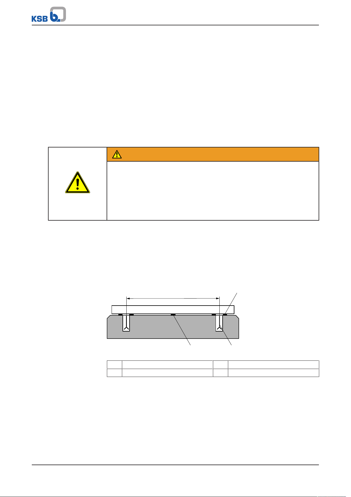
5.3.1 Installation on the foundation
Fig.7: Fitting the shims
L Bolt-to-bolt distance 1 Shim
2 Shim if (1) > 800 mm 3 Foundation bolt
ü The foundation has the required strength and characteristics.
ü The foundation has been prepared in accordance with the dimensions given in
the outline drawing/general arrangement drawing.
1. Position the pump set on the foundation and level it with the help of a spirit
level placed on the shaft and discharge nozzle.
Permissible deviation 0.2 mm/m.
2. Use shims (1) for height compensation, if necessary.
Always fit shims, if any, immediately to the left and right of the foundation
bolts (3) between the baseplate/foundation frame and the foundation.
Etanorm-RX
17 of 56
 Loading...