

KSB Etaline DL Operating Manual
In-line Twin Pump
Etaline DL
Installation/Operating Manual

Legal information/Copyright
Installation/Operating Manual Etaline DL
Original operating manual
All rights reserved. The contents provided herein must neither be distributed, copied, reproduced,
edited or processed for any other purpose, nor otherwise transmitted, published or made available to a
third party without the manufacturer's express written consent.
Subject to technical modification without prior notice.
© KSB SE & Co. KGaA, Frankenthal 08/02/2018

Contents
3 of 52
Etaline DL
Contents
Glossary .................................................................................................................................................. 5
1 General.................................................................................................................................................... 6
1.1 Principles ...........................................................................................................................................................6
1.2 Installation of partly completed machinery....................................................................................................6
1.3 Target group.....................................................................................................................................................6
1.4 Other applicable documents............................................................................................................................6
1.5 Symbols .............................................................................................................................................................6
2 Safety...................................................................................................................................................... 8
2.1 Key to safety symbols/markings.......................................................................................................................8
2.2 General..............................................................................................................................................................8
2.3 Intended use .....................................................................................................................................................8
2.4 Personnel qualification and training...............................................................................................................9
2.5 Consequences and risks caused by non-compliance with this manual .........................................................9
2.6 Safety awareness ..............................................................................................................................................9
2.7 Safety information for the operator/user.....................................................................................................10
2.8 Safety information for maintenance, inspection and installation ..............................................................10
2.9 Unauthorised modes of operation................................................................................................................10
2.10 Electromagnetic compatibility.......................................................................................................................10
3 Transport/Temporary Storage/Disposal............................................................................................. 11
3.1 Checking the condition upon delivery..........................................................................................................11
3.2 Transport.........................................................................................................................................................11
3.3 Storage/preservation......................................................................................................................................11
3.4 Return to supplier...........................................................................................................................................12
3.5 Disposal ...........................................................................................................................................................12
4 Description of the Pump (Set)............................................................................................................. 13
4.1 General description ........................................................................................................................................13
4.2 Product Information as per Regulation No. 547/2012 (for water pumps with a maximum shaft power of
150kW) implementing "Ecodesign" Directive 2009/125/EC........................................................................13
4.3 Designation.....................................................................................................................................................13
4.4 Name plate......................................................................................................................................................14
4.5 Design details..................................................................................................................................................14
4.6 Configuration and function...........................................................................................................................15
4.7 Noise characteristics .......................................................................................................................................16
4.8 Scope of supply...............................................................................................................................................16
4.9 Dimensions and weight..................................................................................................................................16
5 Installation at Site................................................................................................................................ 17
5.1 Safety regulations...........................................................................................................................................17
5.2 Checks to be carried out prior to installation...............................................................................................17
5.3 Installing the pump set ..................................................................................................................................18
5.4 Piping ..............................................................................................................................................................18
5.4.1 Connecting the piping.......................................................................................................................18
5.4.2 Permissible forces and moments at the pump nozzles....................................................................19
5.4.3 Vacuum balance line..........................................................................................................................19
5.4.4 Auxiliary connections.........................................................................................................................20
5.5 Enclosure/insulation .......................................................................................................................................20
5.6 Electrical connection ......................................................................................................................................21
5.6.1 Motor connection inside the terminal box ......................................................................................21
6 Commissioning/Start-up/Shutdown................................................................................................... 24
6.1 Commissioning/Start-up/Shutdown...............................................................................................................24
6.1.1 Prerequisites for commissioning/start-up ......................................................................................... 24
6.1.2 Checking earth conductor connection .............................................................................................24
6.1.3 Checking insulation resistance .......................................................................................................... 24
6.1.4 Filling in lubricants.............................................................................................................................25

Contents
4 of 52
Etaline DL
6.1.5 Priming and venting the pump.........................................................................................................25
6.1.6 Checking the direction of rotation ................................................................................................... 25
6.1.7 Start-up............................................................................................................................................... 26
6.1.8 Checking the shaft seal......................................................................................................................27
6.1.9 Shutdown ...........................................................................................................................................27
6.2 Operating limits..............................................................................................................................................28
6.2.1 Ambient temperature........................................................................................................................28
6.2.2 Frequency of starts.............................................................................................................................29
6.2.3 Fluid handled .....................................................................................................................................29
6.2.4 Voltages and frequencies .................................................................................................................. 30
6.2.5 Maximum permissible speed ............................................................................................................. 30
6.2.6 Altitude...............................................................................................................................................30
6.3 Shutdown/storage/preservation ....................................................................................................................30
6.3.1 Measures to be taken for shutdown ................................................................................................30
6.4 Returning to service .......................................................................................................................................31
7 Servicing/Maintenance........................................................................................................................ 32
7.1 Safety regulations...........................................................................................................................................32
7.2 Servicing/inspection........................................................................................................................................33
7.2.1 Supervision of operation ................................................................................................................... 33
7.2.2 Inspection work..................................................................................................................................35
7.2.3 Lubrication and lubricant change.....................................................................................................35
7.3 Drainage/cleaning ..........................................................................................................................................36
7.4 Dismantling the pump set..............................................................................................................................36
7.4.1 General information/Safety regulations...........................................................................................36
7.4.2 Preparing the pump set..................................................................................................................... 37
7.4.3 Dismantling the complete pump set ................................................................................................37
7.4.4 Removing the back pull-out unit ...................................................................................................... 37
7.4.5 Removing the impeller ......................................................................................................................38
7.4.6 Removing the mechanical seal..........................................................................................................38
7.5 Reassembling the pump set...........................................................................................................................38
7.5.1 General information/Safety regulations...........................................................................................38
7.5.2 Fitting the mechanical seal................................................................................................................39
7.5.3 Fitting the impeller ............................................................................................................................39
7.5.4 Installing the back pull-out unit .......................................................................................................40
7.6 Tightening torques.........................................................................................................................................40
7.7 Spare parts stock.............................................................................................................................................40
7.7.1 Ordering spare parts.......................................................................................................................... 40
7.7.2 Recommended spare parts stock for 2 years' operation to DIN24296...........................................41
8 Trouble-shooting.................................................................................................................................. 42
9 Related Documents.............................................................................................................................. 44
9.1 Typical installation positions..........................................................................................................................44
9.2 General assembly drawing with list of components ....................................................................................46
10 EU Declaration of Conformity............................................................................................................. 47
11 EU Declaration of Conformity............................................................................................................. 48
12 EU Declaration of Conformity............................................................................................................. 49
13 Certificate of Decontamination........................................................................................................... 50
Index ..................................................................................................................................................... 51

Glossary
5 of 52
Etaline DL
Glossary
Back pull-out unit
Pump without pump casing; partly completed
machinery
Certificate of decontamination
A certificate of decontamination is enclosed by the
customer when returning the product to the
manufacturer to certify that the product has been
properly drained to eliminate any environmental
and health hazards arising from components in
contact with the fluid handled.
Close-coupled design
Motor directly fitted to the pump via a flange or a
drive lantern
Discharge line
The pipeline which is connected to the discharge
nozzle
Hydraulic system
The part of the pump in which the kinetic energy
is converted into pressure energy
IE3
Efficiency class to IEC60034-30: 3=Premium
Efficiency (IE = International Efficiency)
In-line design
A pump whose suction and discharge nozzle are
arranged opposite each other and have the same
nominal diameter.
Noise characteristics
The noise emission to be expected, indicated as
sound pressure level LpA in dB(A)
Pump
Machine without drive, additional components or
accessories
Pump set
Complete pump set consisting of pump, drive,
additional components and accessories
Suction lift line/suction head line
The pipeline which is connected to the suction
nozzle
1 General
6 of 52
Etaline DL
1 General
1.1 Principles
This operating manual is supplied as an integral part of the type series indicated on
the front cover. The operating manual describes the proper and safe use of this
equipment in all phases of operation.
The name plate indicates the type series, the main operating data and the material
number/series code. The material number/series code uniquely describes the product
and is used as identification in all further business processes.
In the event of damage, immediately contact your nearest KSB service centre to
maintain the right to claim under warranty.
Noise characteristics. (ðSection4.7,Page16)
1.2 Installation of partly completed machinery
To install partly completed machinery supplied by KSB refer to the sub-sections under
Servicing/Maintenance.
1.3 Target group
This operating manual is aimed at the target group of trained and qualified specialist
technical personnel. (ðSection2.4,Page9)
1.4 Other applicable documents
Table1: Overview of other applicable documents
Document Contents
Data sheet Description of the technical data of the pump (set)
General arrangement drawing/
outline drawing
Description of mating dimensions and installation
dimensions for the pump (set), weights
Drawing of auxiliary connections Description of auxiliary connections
Hydraulic characteristic curve Characteristic curves showing head, NPSH
required, efficiency and power input
General assembly drawing
1)
Sectional drawing of the pump
Sub-supplier product literature1)Operating manuals and other product literature
describing accessories and integrated machinery
components
Spare parts lists
1)
Description of spare parts
Piping layout
1)
Description of auxiliary piping
List of components
1)
Description of all pump components
Assembly drawing
1)
Sectional drawing of the installed shaft seal
For accessories and/or integrated machinery components observe the relevant
manufacturer's product literature.
1.5 Symbols
Table2: Symbols used in this manual
Symbol Description
✓ Conditions which need to be fulfilled before proceeding with the
step-by-step instructions
⊳ Safety instructions
⇨ Result of an action
⇨ Cross-references
1) If agreed to be included in the scope of supply

1 General
7 of 52
Etaline DL
Symbol Description
1.
2.
Step-by-step instructions
Note
Recommendations and important information on how to handle
the product
2 Safety
8 of 52
Etaline DL
2 Safety
!
DANGER
All the information contained in this section refers to hazardous situations.
2.1 Key to safety symbols/markings
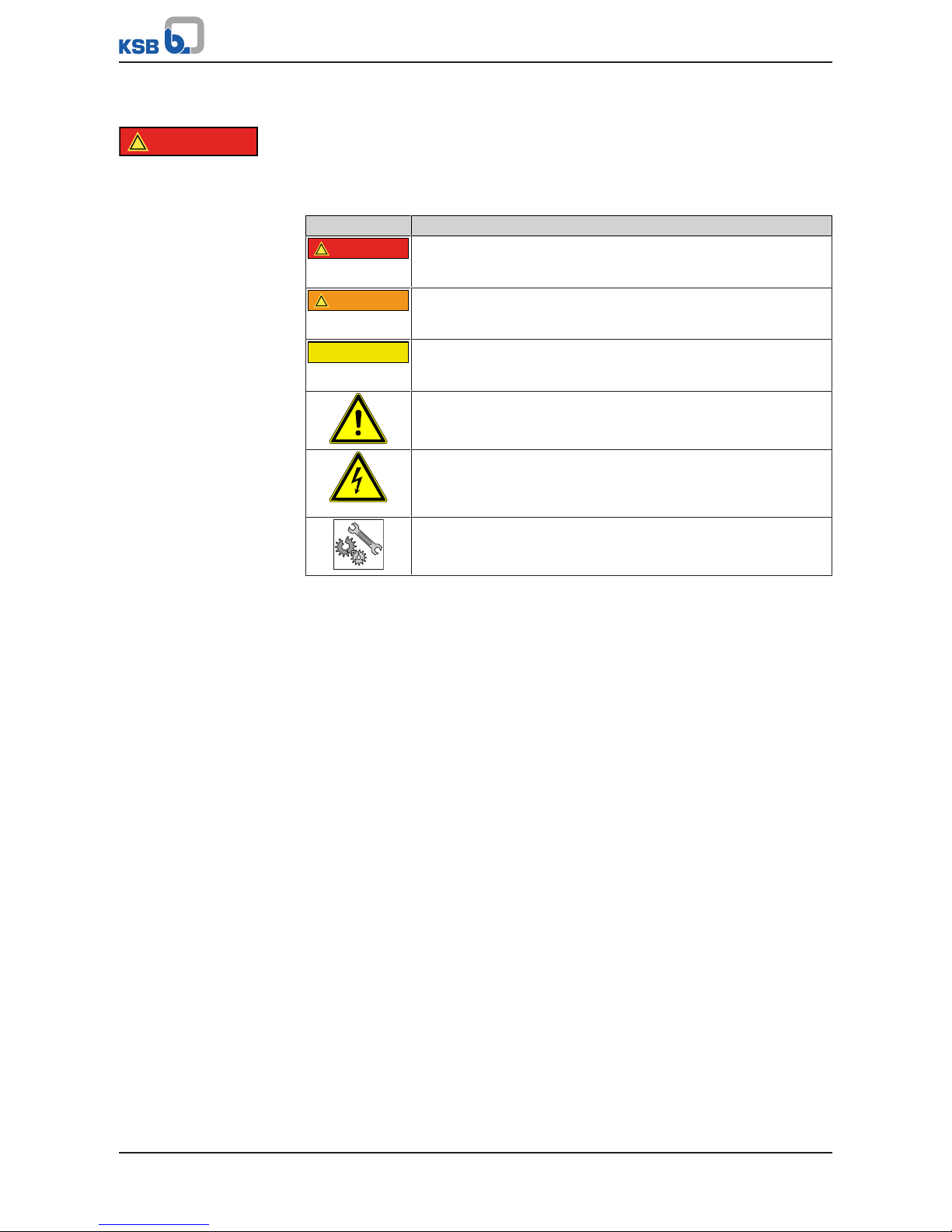
Table3: Definition of safety symbols/markings
Symbol Description
!
DANGER
DANGER
This signal word indicates a high-risk hazard which, if not avoided,
will result in death or serious injury.
!
WARNING
WARNING
This signal word indicates a medium-risk hazard which, if not
avoided, could result in death or serious injury.
CAUTION
CAUTION
This signal word indicates a hazard which, if not avoided, could
result in damage to the machine and its functions.
General hazard
In conjunction with one of the signal words this symbol indicates a
hazard which will or could result in death or serious injury.
Electrical hazard
In conjunction with one of the signal words this symbol indicates a
hazard involving electrical voltage and identifies information about
protection against electrical voltage.
Machine damage
In conjunction with the signal word CAUTION this symbol indicates
a hazard for the machine and its functions.
2.2 General
This operating manual contains general installation, operating and maintenance
instructions that must be observed to ensure safe operation of the system and
prevent personal injury and damage to property.
The safety information in all sections of this manual must be complied with.
The operating manual must be read and understood by the responsible specialist
personnel/operators prior to installation and commissioning.
The contents of this operating manual must be available to the specialist personnel
at the site at all times.
Information attached directly to the product must always be complied with and kept
in a perfectly legible condition at all times. This applies to, for example:
▪ Arrow indicating the direction of rotation
▪ Markings for connections
▪ Name plate
The operator is responsible for ensuring compliance with all local regulations not
taken into account in this operating manual.
The electric drive has been designed and constructed in accordance with the
requirements of Directive 2014/35/EU ("Low-voltage Directive").
2.3 Intended use
▪ The product must not be used in potentially explosive atmospheres.
▪ The pump (set) must only be operated in the fields of application and within the
use limits specified in the other applicable documents.
▪ Only operate pumps/pump sets which are in perfect technical condition.
▪ Only use the pump to handle the fluids described in the data sheet or product
literature of the pump model or variant.
▪ Never operate the pump without the fluid to be handled.

2 Safety
9 of 52
Etaline DL
▪ Observe the minimum flow rates indicated in the data sheet or product literature
(to prevent overheating, bearing damage, etc).
▪ Observe the minimum flow rate and maximum flow rate indicated in the data
sheet or product literature (to prevent overheating, mechanical seal damage,
cavitation damage, bearing damage, etc).
▪ Do not throttle the flow rate on the suction side of the pump (to prevent
cavitation damage).
▪ Consult the manufacturer about any use or mode of operation not described in
the data sheet or product literature.
Prevention of foreseeable misuse
▪ Never open the discharge-side shut-off elements further than permitted.
– The maximum flow rates specified in the product literature or data sheet
would be exceeded.
– Risk of cavitation damage
▪ Never exceed the permissible operating limits and use limits specified in the data
sheet or product literature regarding pressure, temperature, mains voltage,
mains frequency, ambient temperature, motor rating, speed, etc.
▪ Observe all safety information and instructions in this manual.
2.4 Personnel qualification and training
All personnel involved must be fully qualified to transport, install, operate, maintain
and inspect the machinery this manual refers to.
The responsibilities, competence and supervision of all personnel involved in
transport, installation, operation, maintenance and inspection must be clearly
defined by the operator.
Deficits in knowledge must be rectified by means of training and instruction
provided by sufficiently trained specialist personnel. If required, the operator can
commission the manufacturer/supplier to train the personnel.
Training on the pump (set) must always be supervised by technical specialist
personnel.
2.5 Consequences and risks caused by non-compliance with this manual
▪ Non-compliance with this operating manual will lead to forfeiture of warranty
cover and of any and all rights to claims for damages.
▪ Non-compliance can, for example, have the following consequences:
– Hazards to persons due to electrical, thermal, mechanical and chemical
effects and explosions
– Failure of important product functions
– Failure of prescribed maintenance and servicing practices
– Hazard to the environment due to leakage of hazardous substances
2.6 Safety awareness
In addition to the safety information contained in this manual and the intended use,
the following safety regulations shall be complied with:
▪ Accident prevention, health and safety regulations
▪ Explosion protection regulations
▪ Safety regulations for handling hazardous substances
▪ Applicable standards, directives and laws

2 Safety
10 of 52
Etaline DL
2.7 Safety information for the operator/user
▪ The operator shall fit contact guards for hot, cold and moving parts and check
that the guards function properly.
▪ Do not remove any contact guards during operation.
▪ Provide the personnel with protective equipment and make sure it is used.
▪ Contain leakages (e.g. at the shaft seal) of hazardous fluids handled (e.g.
explosive, toxic, hot) so as to avoid any danger to persons and the environment.
Adhere to all relevant laws.
▪ Eliminate all electrical hazards. (In this respect refer to the applicable national
safety regulations and/or regulations issued by the local energy supply
companies.)
▪ If shutting down the pump does not increase potential risk, fit an emergency-
stop control device in the immediate vicinity of the pump (set) during pump set
installation.
2.8 Safety information for maintenance, inspection and installation
▪ Modifications or alterations of the pump are only permitted with the
manufacturer's prior consent.
▪ Use only original spare parts or parts authorised by the manufacturer. The use of
other parts can invalidate any liability of the manufacturer for resulting damage.
▪ The operator ensures that maintenance, inspection and installation is performed
by authorised, qualified specialist personnel who are thoroughly familiar with
the manual.
▪ Only carry out work on the pump (set) during standstill of the pump.
▪ Only perform work on the pump set when it has been disconnected from the
power supply (de-energised).
▪ The pump casing must have cooled down to ambient temperature.
▪ Pump pressure must have been released and the pump must have been drained.
▪ When taking the pump set out of service always adhere to the procedure
described in the manual. (ðSection6.1.9,Page27) (ðSection6.3,Page30)
▪ Decontaminate pumps which handle fluids posing a health hazard.
(ðSection7.3,Page36)
▪ As soon as the work has been completed, re-install and re-activate any safety-
relevant devices and protective devices. Before returning the product to service,
observe all instructions on commissioning.
2.9 Unauthorised modes of operation
Never operate the pump (set) outside the limits stated in the data sheet and in this
manual.
The warranty relating to the operating reliability and safety of the supplied pump
(set) is only valid if the equipment is used in accordance with its intended use.
2.10 Electromagnetic compatibility
When operating the motor on a frequency inverter always observe the frequency
inverter manufacturer's information on compliance with the Electromagnetic
Compatibility Directive. Take additional measures to ensure compliance with the
Directive and obtain a connection approval from the local energy supply company, if
necessary.
3 Transport/Temporary Storage/Disposal
11 of 52
Etaline DL
3 Transport/Temporary Storage/Disposal
3.1 Checking the condition upon delivery
1. On transfer of goods, check each packaging unit for damage.
2. In the event of in-transit damage, assess the exact damage, document it and
notify KSB or the supplying dealer and the insurer about the damage in writing
immediately.
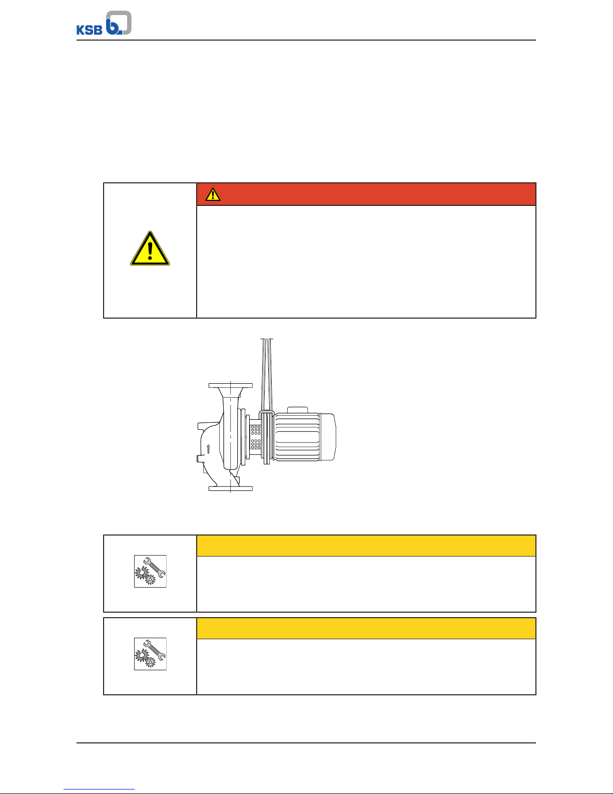
3.2 Transport
DANGER
The pump (set) could slip out of the suspension arrangement
Danger to life from falling parts!
▷ Always transport the pump (set) in the specified position.
▷ Never attach the suspension arrangement to the free shaft end or the motor
eyebolt.
▷ Give due attention to the weight data and the centre of gravity.
▷ Observe the applicable local health and safety regulations.
▷ Use suitable, permitted lifting accessories, e.g. self-tightening lifting tongs.
To transport the pump/pump set suspend it from the lifting tackle as shown.
Fig.1: Transporting the pump set
3.3 Storage/preservation
CAUTION
Damage during storage by humidity, dirt or vermin
Corrosion/contamination of the pump (set)!
▷ For short-term outdoor storage cover the pump (set) or the packaged pump
(set) and accessories with waterproof material.
CAUTION
Wet, contaminated or damaged openings and connections
Leakage or damage to the pump!
▷ Clean and cover pump openings and connections as required prior to putting
the pump into storage.
3 Transport/Temporary Storage/Disposal
12 of 52
Etaline DL
If commissioning is to take place some time after delivery, we recommend that the
following measures be taken for pump (set) storage.
▪ Store the pump (set) in a dry, protected room where the atmospheric humidity is
as constant as possible.
▪ Rotate the shaft by hand once a month, e.g. via the motor fan.
▪ Exposed locating surfaces (shaft ends, flange faces, centring spigots, connector
contacts) are treated with a layer of temporary corrosion protection (< 6 months)
for transport. Take suitable corrosion protection measures for extended storage
periods.
▪ Replace closed rolling element bearings after 48 months of storage.
If properly stored indoors, the equipment is protected for a maximum of 12months.
New pumps/pump sets are supplied by our factory duly prepared for storage.
For storing a pump (set) which has already been operated, observe the measures to
be taken for shutdown. (ðSection6.3.1,Page30)
3.4 Return to supplier
1. Drain the pump as per operating instructions. (ðSection7.3,Page36)
2. Always flush and clean the pump, particularly if it has been used for handling
noxious, explosive, hot or other hazardous fluids.
3. If the pump set has handled fluids whose residues could lead to corrosion
damage in the presence of atmospheric humidity or could ignite upon contact
with oxygen, the pump set must also be neutralised, and anhydrous inert gas
must be blown through the pump to ensure drying.
4. Always complete and enclose a certificate of decontamination when returning
the pump (set).
Always indicate any safety and decontamination measures taken.
(ðSection13,Page50)
NOTE
If required, a blank certificate of decontamination can be downloaded from the
following web site: www.ksb.com/certificate_of_decontamination
3.5 Disposal
WARNING
Fluids handled, consumables and supplies which are hot and/or pose a health
hazard
Hazard to persons and the environment!
▷ Collect and properly dispose of flushing fluid and any fluid residues.
▷ Wear safety clothing and a protective mask if required.
▷ Observe all legal regulations on the disposal of fluids posing a health hazard.
1. Dismantle the pump (set).
Collect greases and other lubricants during dismantling.
2. Separate and sort the pump materials, e.g. by:
- Metals
- Plastics
- Electronic waste
- Greases and other lubricants
3. Dispose of materials in accordance with local regulations or in another
controlled manner.

4 Description of the Pump (Set)
13 of 52
Etaline DL
4 Description of the Pump (Set)
4.1 General description
▪ Non-self-priming in-line pump with low-voltage asynchronous motor to
IEC60034
Pump for handling clean or aggressive fluids which are neither chemically nor
mechanically aggressive to the pump materials.
4.2 Product Information as per Regulation No. 547/2012 (for water pumps
with a maximum shaft power of 150kW) implementing "Ecodesign"
Directive 2009/125/EC
▪ Minimum efficiency index: see name plate, key to name plate
▪ The benchmark for the most efficient water pumps is MEI ≥ 0.70.
▪ Year of construction: see name plate, key to name plate
▪ Manufacturer’s name or trade mark, commercial registration number and place
of manufacture: see data sheet or order documentation
▪ Product’s type and size identificator: see name plate, key to name plate
▪ Hydraulic pump efficiency (%) with trimmed impeller: see data sheet
▪ Pump performance curves, including efficiency characteristics: see documented
characteristic curve
▪ The efficiency of a pump with a trimmed impeller is usually lower than that of a
pump with full impeller diameter. Trimming of the impeller will adapt the pump
to a fixed duty point, leading to reduced energy consumption. The minimum
efficiency index (MEI) is based on the full impeller diameter.
▪ Operation of this water pump with variable duty points may be more efficient
and economic when controlled, for example, by the use of a variable speed drive
that matches the pump duty to the system.
▪ Information on dismantling, recycling and disposal after decommissioning:
(ðSection3.5,Page12)
▪ Information on benchmark efficiency or benchmark efficiency graph for
MEI=0.70(0.40) for the pump based on the model shown in the Figure are
available at: http://www.europump.org/efficiencycharts
4.3 Designation
Example:
ETLD
032-032-080 GG X AV 11 D 2
Table4: Designation key
Code Description
ETLD Pump type
ETLD Etaline DL
032 Nominal suction nozzle diameter [mm]
032 Nominal discharge nozzle diameter [mm]
080 Nominal impeller diameter [mm]
G Casing material
G Grey cast iron
G Impeller material if different from casing material
G Grey cast iron
P Polysulphone
X Additional code
X Special design BT3D, BT3
A Casing cover
A Conical seal chamber
V Sealing system
4 Description of the Pump (Set)
14 of 52
Etaline DL
Code Description
V V Conical seal chamber with vent
A Conical seal chamber
11 Seal code
11 Mechanical seal material BQ1EGG
D Scope of supply
D Pump with motor
2 Shaft unit
2 SU 12
3 SU 14
6 SU 16
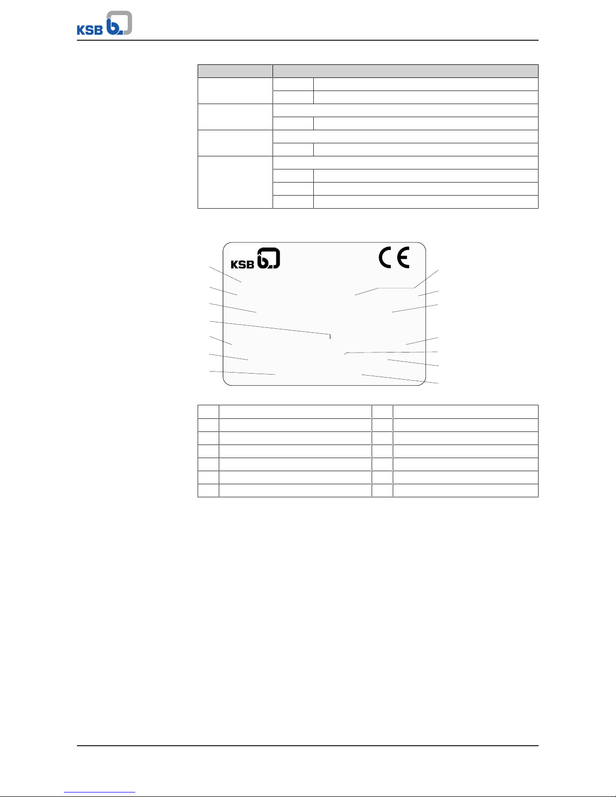
4.4 Name plate
ETLD 032-032-080 GP AV11D2002
Etaline DL 48270000 2016w15
MEI > 0,4
ɳ = --,-%
3~ Y∆ 400/230 V 0,48/0,83 A 0,12 kW
cosφ 0,67 1405 1/min 50 Hz
TH.Cl 155(F) IP55
1
2
3
4
5
6
7
8
9
10
11
12
13
14
Johann-Klein-Straße 9
Deutschland
67227 Frankenthal
KSB SE & Co. KGaA
Fig.2: Name plate (example)
1 Type series code, size and version 2 Type series
3 Minimum efficiency index 4 Phase current
5 Voltage range 6 Power factor
7 Thermal class 8 Material number (if applicable)
9 Year of construction 10 Efficiency
11 Nominal power 12 Speed
13 Frequency 14 Enclosure
4.5 Design details
Design
▪ Close-coupled design/in-line design
▪ Single-stage
▪ Horizontal installation/ vertical installation
▪ Rigid connection between pump and motor
Pump casing
▪ Radially split volute casing
▪ In-line design
Drive
▪ Surface-cooled squirrel-cage motor to KSB standard
▪ Efficiency class IE3 to IEC60034-30 (≥0.75kW)
▪ Winding 50Hz, 1~220-240V / 3~220-240V / 3~380-420V ≤1.1kW
▪ Winding 50Hz, 3~220-240V / 3~380-420V ≥ 1.8kW

4 Description of the Pump (Set)
15 of 52
Etaline DL
▪ Type of construction IMB14
▪ Enclosure IP55
▪ Duty cycle: continuous duty S1
▪ Thermal class F
Shaft seal
▪ KSB mechanical seal
Impeller type
▪ Closed radial impeller
Bearings
▪ Radial ball bearings in the motor housing
▪ Grease lubrication
Automation
Automation options:
▪ PumpDrive
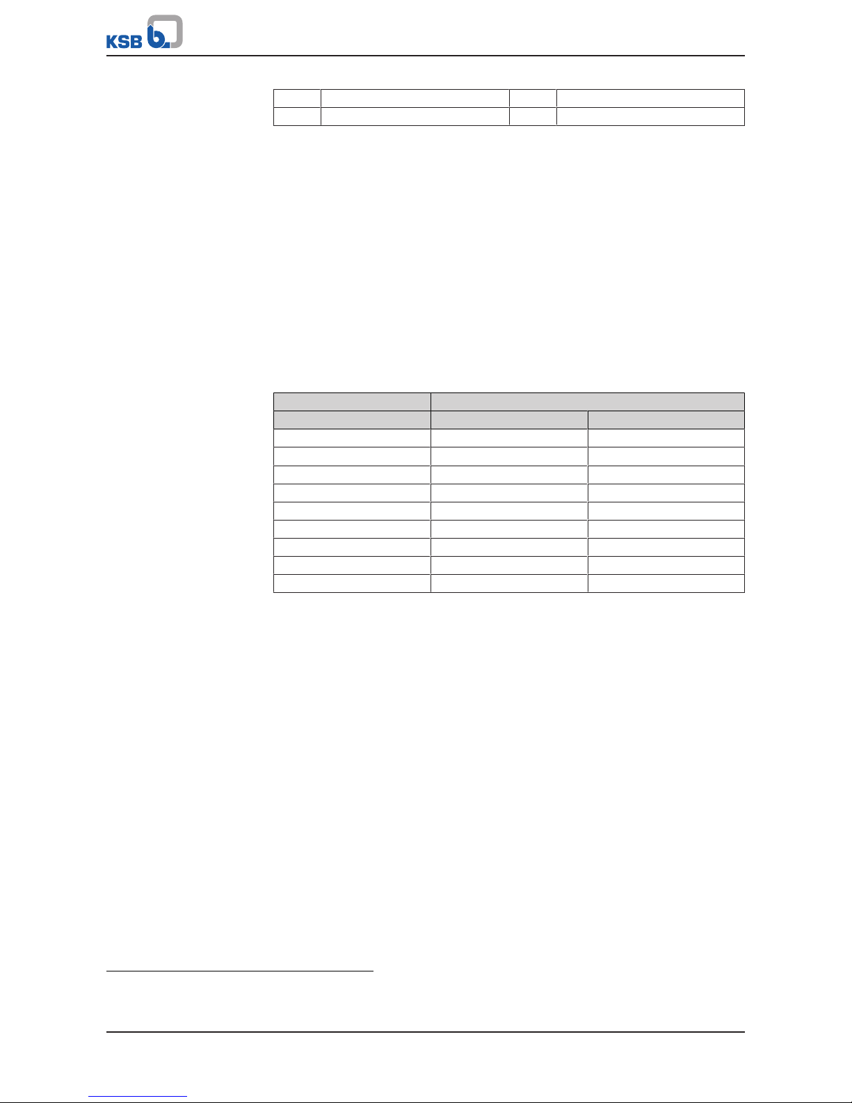
4.6 Configuration and function
3
4
11
9
7
6
10
1
5
8
2
Fig.3: Sectional drawing
1 Discharge nozzle 2 Suction nozzle
3 Clearance gap 4 Impeller
5 Shaft seal 6 Casing cover
7 Shaft 8 Drive lantern
4 Description of the Pump (Set)
16 of 52
Etaline DL
9 Rolling element bearing 10 Motor housing
11 Rolling element bearing
Design
The pump is designed with a radial fluid inlet (suction nozzle) and a radial outlet
(discharge nozzle) arranged on the same axis. The hydraulic system is rigidly
connected to the motor by a shaft coupling.
Function
The fluid enters the pump via the suction nozzle (2) and is accelerated outward by
the rotating impeller (4). In the flow passage of the pump casing the kinetic energy
of the fluid is converted into pressure energy. The fluid is pumped to the discharge
nozzle (1), where it leaves the pump. The clearance gap (3) prevents any fluid from
flowing back from the casing to the suction nozzle. At the rear side of the impeller,
the shaft (7) enters the casing via the casing cover (6). The shaft passage through the
cover is sealed to the atmosphere with a dynamic shaft seal (5). The shaft runs in
rolling element bearings (9 and 11), which are supported by a motor housing (10)
linked with the pump casing and/or casing cover via the drive lantern (8).
Sealing
The pump is sealed by a standardised mechanical seal.
4.7 Noise characteristics
Table5: Surface sound pressure level L
pA
2)3)
Rated power input P
N
Pump set
[kW] 1450rpm 2900rpm
0,12 36 40
0,18 36 40
0,25 - 46
0,37 36 46
0,55 - 46
0,75 37 52
1,1 - 52
1,8 - 53
3 - 53
4.8 Scope of supply
Depending on the model, the following items are included in the scope of supply:
▪ Pump set
or
▪ Motor incl. casing cover
Accessories
▪ Pump foot for vertical installation of the drive
4.9 Dimensions and weight
For dimensions and weights please refer to the type series booklet of the pump.
2) Spatial average; as per ISO 3744 and EN 12639; valid for pump operation in the Q/Qopt = 0.8 - 1.1 range and for non-
cavitating operation. If noise levels are to be guaranteed: Add +3dB for measuring and constructional tolerance.
3) Increase for 60Hz operation: 3500rpm +3dB; 1750rpm +1dB
 Loading...