

KSB ECOLINE GLB, ECOLINE PTF, ECOLINE SCF, ECOLINE GTB, ECOLINE GTV Operating Manual
...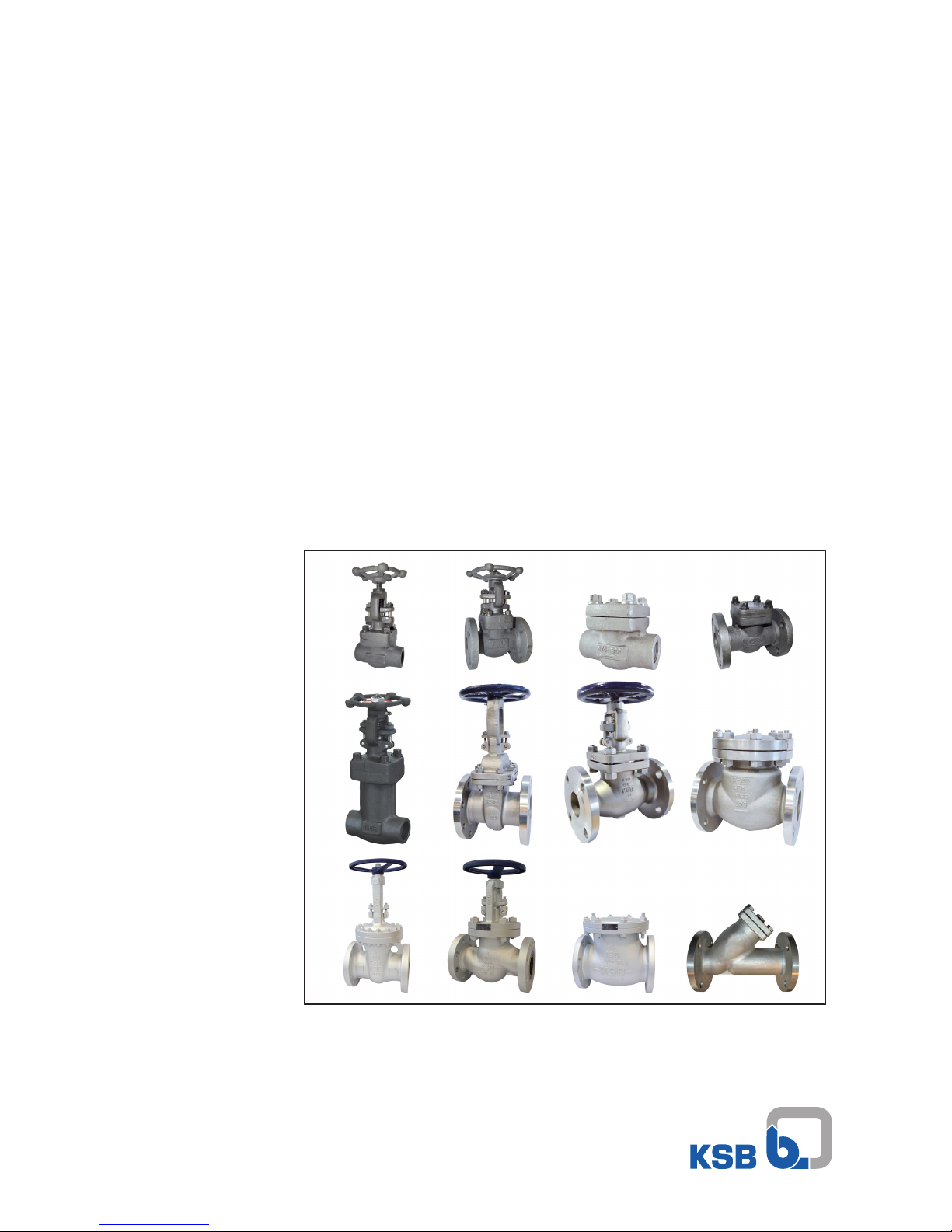
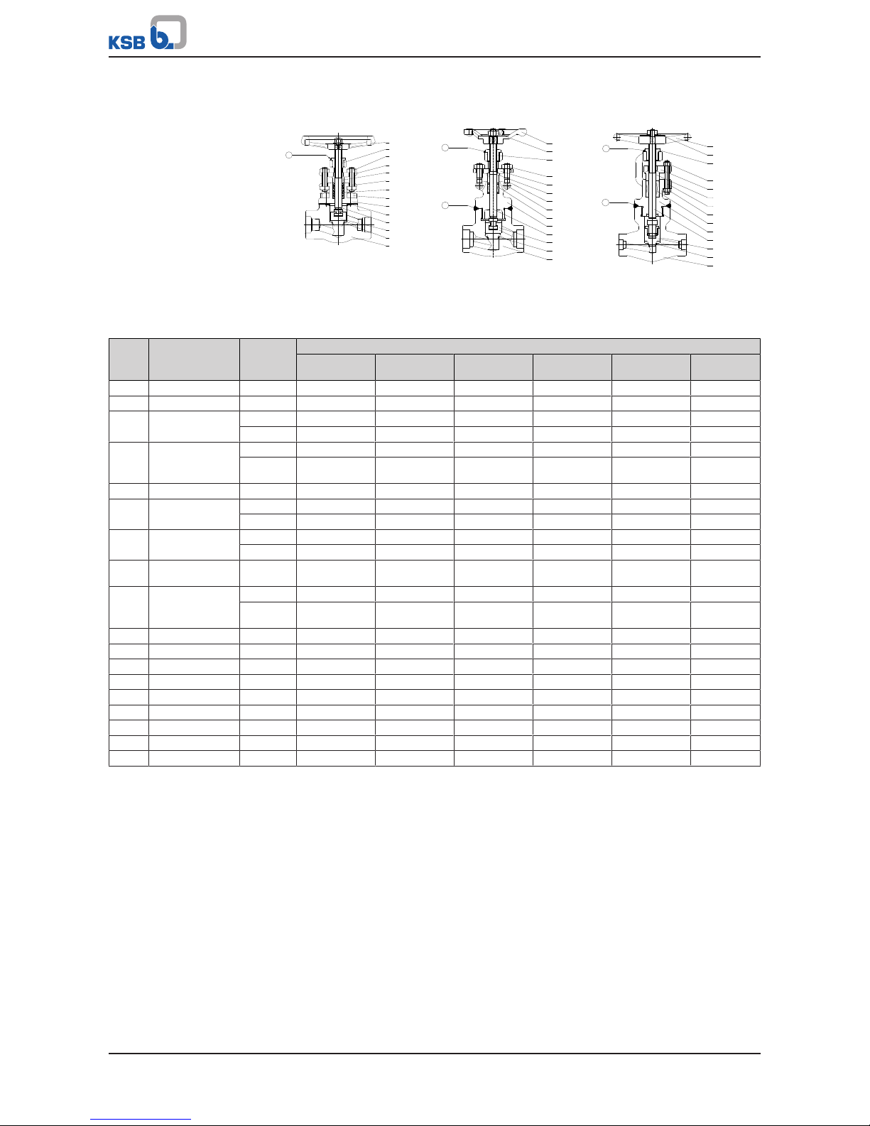
ECOLINE GLF/GTF/PTF/SCF/FYF
ECOLINE GLB/GTB
ECOLINE GLV/GTV/SCV
ECOLINE GLC/GTC/SCC/FYC
Operating Manual

Legal information/Copyright
Operating Manual
Original operating manual
All rights reserved. The contents provided herein must neither be distributed, copied, reproduced,
edited or processed for any other purpose, nor otherwise transmitted, published or made available to a
third party without the manufacturer's express written consent.
Subject to technical modification without prior notice.
© KSB Valves Changzhou Co., Ltd., China12/12/2016

Contents
3 of 100
Contents
Glossary .................................................................................................................................................. 5
1 General.................................................................................................................................................... 6
1.1 Principles ...........................................................................................................................................................6
1.2 Target group.....................................................................................................................................................6
1.3 Other applicable documents............................................................................................................................6
1.4 Symbols .............................................................................................................................................................6
2 Safety...................................................................................................................................................... 7
2.1 Key to safety symbols/markings.......................................................................................................................7
2.2 General..............................................................................................................................................................7
2.3 Intended use .....................................................................................................................................................8
2.4 Personnel qualification and training...............................................................................................................8
2.5 Consequences and risks caused by non-compliance with this manual .........................................................8
2.6 Safety awareness ..............................................................................................................................................8
2.7 Safety information for the operator/user.......................................................................................................9
2.8 Safety information for maintenance, inspection and installation ................................................................9
2.9 Unauthorised modes of operation..................................................................................................................9
3 Transport/Temporary Storage/Disposal............................................................................................. 10
3.1 Checking the condition upon delivery..........................................................................................................10
3.2 Transport.........................................................................................................................................................10
3.3 Storage/preservation......................................................................................................................................11
3.4 Return to supplier...........................................................................................................................................12
3.5 Disposal ...........................................................................................................................................................12
4 Valve Description ................................................................................................................................. 13
4.1 General description ........................................................................................................................................13
4.2 Marking...........................................................................................................................................................13
4.3 Globe Valves to ANSI/ASME with Gland Packing .........................................................................................14
4.4 Bellows-type Globe Valves to ANSI/ASME.....................................................................................................30
4.5 Gate Valves to ANSI/ASME.............................................................................................................................38
4.6 Lift Check Valves to ANSI/ASME ....................................................................................................................57
4.7 Swing Check Valves to ANSI/ASME................................................................................................................64
4.8 Strainers to ANSI/ASME..................................................................................................................................76
5 Installation at Site................................................................................................................................ 81
5.1 General information/Safety regulations .......................................................................................................81
5.2 Installation position and location..................................................................................................................82
5.3 Welding into the pipeline..............................................................................................................................83
5.4 Valves with actuator.......................................................................................................................................83
5.5 Insulation ........................................................................................................................................................84
6 Commissioning/Start-up/Shutdown................................................................................................... 85
6.1 Commissioning/start-up .................................................................................................................................85
6.2 Shutdown........................................................................................................................................................87
7 Servicing/Maintenance........................................................................................................................ 88
7.1 Safety regulations...........................................................................................................................................88
7.2 Maintenance...................................................................................................................................................88
8 Trouble-shooting.................................................................................................................................. 90
9 EU Declaration of Conformity............................................................................................................. 91
9.1 EU Declaration of Conformity for ECOLINE FYF 800, GLF 2500, GLB 800, GTF 2500, GTB 800, PTF 2500,
SCF 2500 ..........................................................................................................................................................91
9.2 EU Declaration of Conformity for ECOLINE GTC, GLC, SCC, GLF, GTF, SCF, PTF .........................................92
9.3 EU Declaration of Conformity for ECOLINE FYC...........................................................................................93
9.4 EU Declaration of Conformity for ECOLINE GLV, GTV, SCV.........................................................................94

Contents
4 of 100
9.5 EU Declaration of Conformity for ECOLINE GLB 150-600 ............................................................................95
Index ..................................................................................................................................................... 96

Glossary
5 of 100
Glossary
PED
The 97/23/EC or 2014/68/EU directive, also known
as the Pressure Equipment Directive, sets out the
requirements to be met by pressure equipment
intended to be placed on the market in the
European economic area.
Technical literature
Refer to the product catalogue for the technical
literature on our products at www.ksb.com.
1 General
6 of 100
1 General
1.1 Principles
This operating manual is supplied as an integral part of the type series and variants
indicated on the front cover. The manual describes the proper and safe use of this
equipment in all phases of operation.
In the event of damage, immediately contact the KSB sales organisation responsible
in order to maintain the right to claim under warranty.
1.2 Target group
This operating manual is aimed at the target group of trained and qualified specialist
technical personnel.
1.3 Other applicable documents
Table1: Overview of other applicable documents
Document Contents
Type series booklet Description of the valve
Flow characteristics
1)
Information on Kv and zeta values
General assembly drawing
2)
Sectional drawing of the valve
Sub-supplier product literature3)Operating manuals and other product literature
for the accessories
Observe the relevant manufacturer's product literature for the accessories.
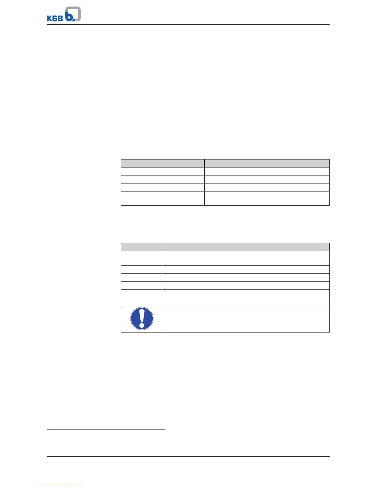
1.4 Symbols
Table2: Symbols used in this manual
Symbol Description
✓ Conditions which need to be fulfilled before proceeding with the
step-by-step instructions
⊳ Safety instructions
⇨ Result of an action
⇨ Cross-references
1.
2.
Step-by-step instructions
Note
Recommendations and important information on how to handle
the product
1) If any
2) If inclusion in the scope of supply has been agreed; otherwise refer to the type series booklet.
3) If inclusion in the scope of supply has been agreed.
2 Safety
7 of 100
2 Safety
!
DANGER
All the information contained in this section refers to hazardous situations.
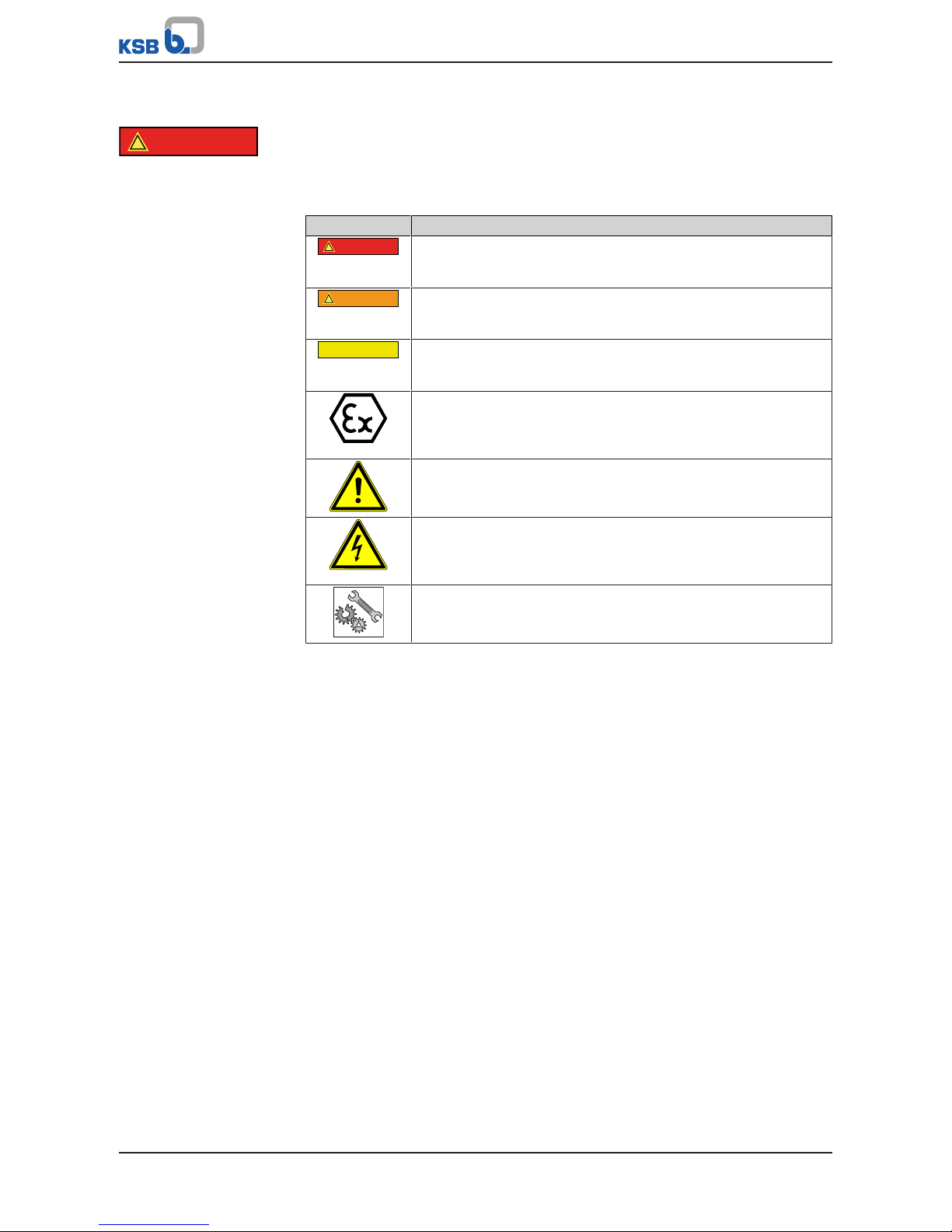
2.1 Key to safety symbols/markings
Table3: Definition of safety symbols/markings
Symbol Description
!
DANGER
DANGER
This signal word indicates a high-risk hazard which, if not avoided,
will result in death or serious injury.
!
WARNING
WARNING
This signal word indicates a medium-risk hazard which, if not
avoided, could result in death or serious injury.
CAUTION
CAUTION
This signal word indicates a hazard which, if not avoided, could
result in damage to the machine and its functions.
Explosion protection
This symbol identifies information about avoiding explosions in
potentially explosive atmospheres in accordance with Directive
2014/34/EU (ATEX).
General hazard
In conjunction with one of the signal words this symbol indicates a
hazard which will or could result in death or serious injury.
Electrical hazard
In conjunction with one of the signal words this symbol indicates a
hazard involving electrical voltage and identifies information about
protection against electrical voltage.
Machine damage
In conjunction with the signal word CAUTION this symbol indicates
a hazard for the machine and its functions.
2.2 General
This manual contains general installation, operating and maintenance instructions
that must be observed to ensure safe valve operation and prevent personal injury
and damage to property.
The safety information in all sections of this manual must be complied with.
The operating manual must be read and fully understood by the specialist personnel/
operators responsible prior to installation and commissioning.
The contents of this operating manual must be available to the specialist personnel
at the site at all times.
Instructions and information attached directly to the valve must always be complied
with and kept in a perfectly legible condition at all times. This applies to, for
example: flow direction arrow, manufacturer, type designation, nominal pressure,
nominal size, year of construction and material.
The operator is responsible for ensuring compliance with all local regulations not
taken into account in this manual.
The design, manufacture and the testing of the valves are subject to a QM system to
DINENISO9001 as well as the European Pressure Equipment Directive 97/23/EC.
Compliance with these requirements, however, is based on normal, predominantly
static loading.
Valves exposed to creep-rupture conditions have a limited service life and have to
meet the applicable regulations stipulated in the technical codes.
In the case of customised special variants, further restrictions may apply with regard
to the operating mode and service life. Please refer to the relevant sales literature for
this information.

2 Safety
8 of 100
This operating manual does not take into account:
▪ Any eventualities or incidents which may occur during installation performed by
the customer, operation and maintenance.
▪ Local regulations; the operator must ensure that such regulations are strictly
observed by all, including the personnel called in for installation.
2.3 Intended use
▪ Only operate valves which are in perfect technical condition.
▪ Do not operate partially assembled valves.
▪ The valve must only handle the fluids specified in the product literature.
▪ Only operate the valve within the permissible operating range specified for
pressure and temperature.
▪ Consult the manufacturer about any other modes of operation not described in
the product literature.
Prevention of foreseeable misuse
▪ Never exceed the permissible operating limits specified in the data sheet or
product literature regarding pressure, temperature, etc.
▪ Observe all safety information and instructions in this operating manual.
2.4 Personnel qualification and training
All personnel involved must be fully qualified to transport, install, operate, maintain
and inspect the product this manual refers to and be fully aware of the interaction
between the valve and the system.
The responsibilities, competence and supervision of all personnel involved in
transport, installation, operation, maintenance and inspection must be clearly
defined by the operator.
Deficits in knowledge must be rectified by means of training and instruction
provided by sufficiently trained specialist personnel. If required, the operator can
commission the manufacturer/supplier to train the personnel.
Hands-on training at the valve must always be supervised by specialist technical
personnel.
2.5 Consequences and risks caused by non-compliance with this manual
▪ Non-compliance with this operating manual will lead to forfeiture of warranty
cover and of any and all rights to claims for damages.
▪ Non-compliance can, for example, have the following consequences:
– Hazards to persons due to electrical, thermal, mechanical and chemical
effects and explosions
– Failure of important product functions
– Failure of prescribed maintenance and servicing practices
– Hazard to the environment due to leakage of hazardous substances
2.6 Safety awareness
In addition to the safety information contained in this manual and the intended use,
the following safety regulations shall be complied with:
▪ Accident prevention, health and safety regulations
▪ Explosion protection regulations
▪ Safety regulations for handling hazardous substances
▪ Applicable standards, directives and laws

2 Safety
9 of 100
2.7 Safety information for the operator/user
Actuator-operated valves are intended for use in areas which cannot be accessed by
unauthorised persons. Operation of these valves in areas which can be accessed by
unauthorised persons is only permitted if appropriate protective devices are fitted at
the site. This must be ensured by the operator.
▪ The operator shall fit contact guards for hot, cold and moving parts and check
that the guards function properly.
▪ Do not remove any contact guards during operation.
▪ Provide the personnel with protective equipment and make sure it is used.
▪ Contain leakages (e.g. at the stem seal) of hazardous fluids (e.g. explosive, toxic,
hot) so as to avoid any danger to persons and the environment. Adhere to all
relevant laws.
▪ Eliminate all electrical hazards. (In this respect refer to the applicable national
safety regulations and/or regulations issued by the local energy supply
companies.)
2.8 Safety information for maintenance, inspection and installation
▪ Modifications or alterations of the valve require the manufacturer's prior
consent.
▪ Use only original spare parts or parts authorised by the manufacturer. The use of
other parts can invalidate any liability of the manufacturer for resulting damage.
▪ The operator ensures that maintenance, inspection and installation is performed
by authorised, qualified specialist personnel who are thoroughly familiar with
the manual.
▪ Carry out work on the valve during standstill only.
▪ The valve body must have cooled down to ambient temperature.
▪ The pressure in the valve body must have been released and the valve must have
been drained.
▪ When taking the valve out of service always adhere to the procedure described
in the manual.
▪ Decontaminate valves which handle fluids posing a health hazard.
▪ As soon as the work has been completed, re-install and/or re-activate any safety-
relevant and protective devices. Before returning the product to service, observe
all instructions on commissioning.
2.9 Unauthorised modes of operation
Never operate the valve outside the limits stated in the data sheet and in this
operating manual.
The warranty relating to the operating reliability and safety of the valve supplied is
only valid if the valve is used in accordance with its intended use.
(ðSection2.3,Page8)
Shut-off valves are not suitable for regulating volume flow.
Gate valves are used in such a way that they are either fully open or fully closed. An
intermediate position (throttling function) is not permitted.
3 Transport/Temporary Storage/Disposal
10 of 100
3 Transport/Temporary Storage/Disposal
3.1 Checking the condition upon delivery
1. On transfer of goods, check each packaging unit for damage.
2. In the event of in-transit damage, assess the exact damage, document it and
notify KSB or the supplying dealer (as applicable) and the insurer about the
damage in writing immediately.
3.2 Transport
Always close the valve manually before transporting it. The valve is delivered ready
for operation and its line connection ports may still be closed with caps, if applicable.
Original spare parts are only ready for operation following assembly/installation and
subsequent shell and leak testing of the valve.
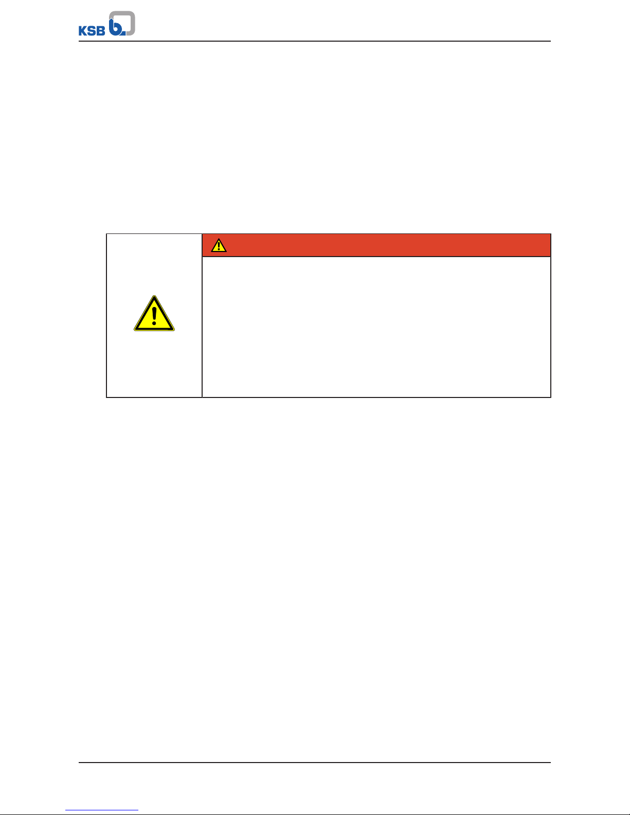
DANGER
The valve could slip out of the suspension arrangement
Danger to life from falling parts!
▷ Only transport the valve in the specified position.
▷ Never suspend the valve from its handwheel.
▷ Pay attention to the weight data and the centre of gravity.
▷ Observe the applicable local accident prevention regulations.
▷ Use suitable, permitted lifting accessories.
▷ Transport devices (if any) on the actuator may not be suitable for being
attached to a suspension arrangement in order to transport the valve/actuator
assembly. Refer to the actuator operating manual for the permissible loads.
To transport the valve, suspend it from the lifting tackle as illustrated.

3 Transport/Temporary Storage/Disposal
11 of 100
Fig.1: Transporting the valve
3.3 Storage/preservation
If commissioning is to take place some time after delivery, we recommend that the
following measures be taken for storing the valve:
CAUTION
Incorrect storage
Damage to the valve due to dirt, corrosion, moisture and/or frost!
▷ Store the valve in a dust- and vibration-free, frost-proof room where the
atmospheric humidity is as constant as possible (use suitable caps or film for
protection).
▷ Close the valve using little force and store in the closed position.
▷ Protect the valve from contact with solvents, lubricants, fuels or other
chemicals.
If properly stored indoors, the equipment is protected for a maximum of 12 months.
NOTE
For actuated valves, also observe the actuator's operating manual.
3 Transport/Temporary Storage/Disposal
12 of 100
3.4 Return to supplier
1. Drain the valve as described in the manual.
2. Always flush and clean the valve, particularly if it has been used for handling
noxious, explosive, hot or other hazardous fluids.
3. If the fluids handled by the system leave residues which might lead to corrosion
damage when coming into contact with atmospheric humidity, or which might
ignite when coming into contact with oxygen, the valve must also be neutralised
and blown through with anhydrous inert gas for drying purposes.
4. When returning valves used for handling Fluids in Group 1 always complete and
enclose a certificate of decontamination.
Always indicate any safety and decontamination measures taken.
NOTE
If required, a blank certificate of decontamination can be downloaded from the
KSB web site at: www.ksb.com/certificate_of_decontamination
3.5 Disposal
WARNING
Fluids, consumables and supplies which are hot and/or pose a health hazard
Hazard to persons and the environment!
▷ Collect and properly dispose of flushing fluid and any residues of the fluid
handled.
▷ Wear safety clothing and a protective mask, if required.
▷ Observe all legal regulations on the disposal of fluids posing a health hazard.
1. Dismantle the valve.
Collect greases and other lubricants during dismantling.
2. Separate and sort the valve materials, e.g. by:
- Metals
- Plastics
- Electronic waste
- Greases and other lubricants
3. Dispose of materials in accordance with current regulations or in another
controlled manner.
4 Valve Description
13 of 100
4 Valve Description
4.1 General description
The sectional drawings below provide examples of the general design/configuration
of the valve. For additional and more detailed information, refer to the respective
type series booklet.
4.2 Marking
Table4: General marking
Parameter Value/Marking
Nominal size NPS (inch) ...
Nominal pressure class Class ...
Manufacturer KSB
Type series/Model ECOLINE...
Year of construction 20..
Material .......
Flow direction arrow →
Traceability of the material .......
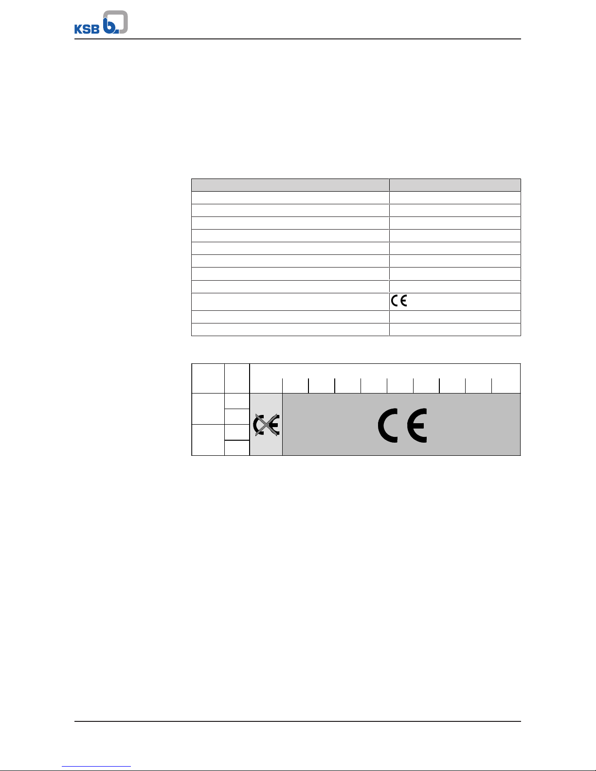
CE markingPED
Identification number of the notified body 0036
Customer's marking e.g. plant/system No., etc.
The CE marking on the valve indicates that it is in conformity with the European
Pressure Equipment Directive 97/23/EC.
Fluids in Groups 1 and 2
Class PN DN
≤25 32 40 50 65 80 100 125 150 ≥200
10
16
25
≥
≥40
150
300
Fluid groups
Group 1 comprises fluids defined as
▪ Explosive
▪ Extremely flammable
▪ Highly flammable
▪ Flammable: The maximum allowable temperature is above flashpoint
▪ Very toxic
▪ Toxic
▪ Oxidising
Group 2 comprises all other fluids not referred to in Group 1.
4 Valve Description
14 of 100
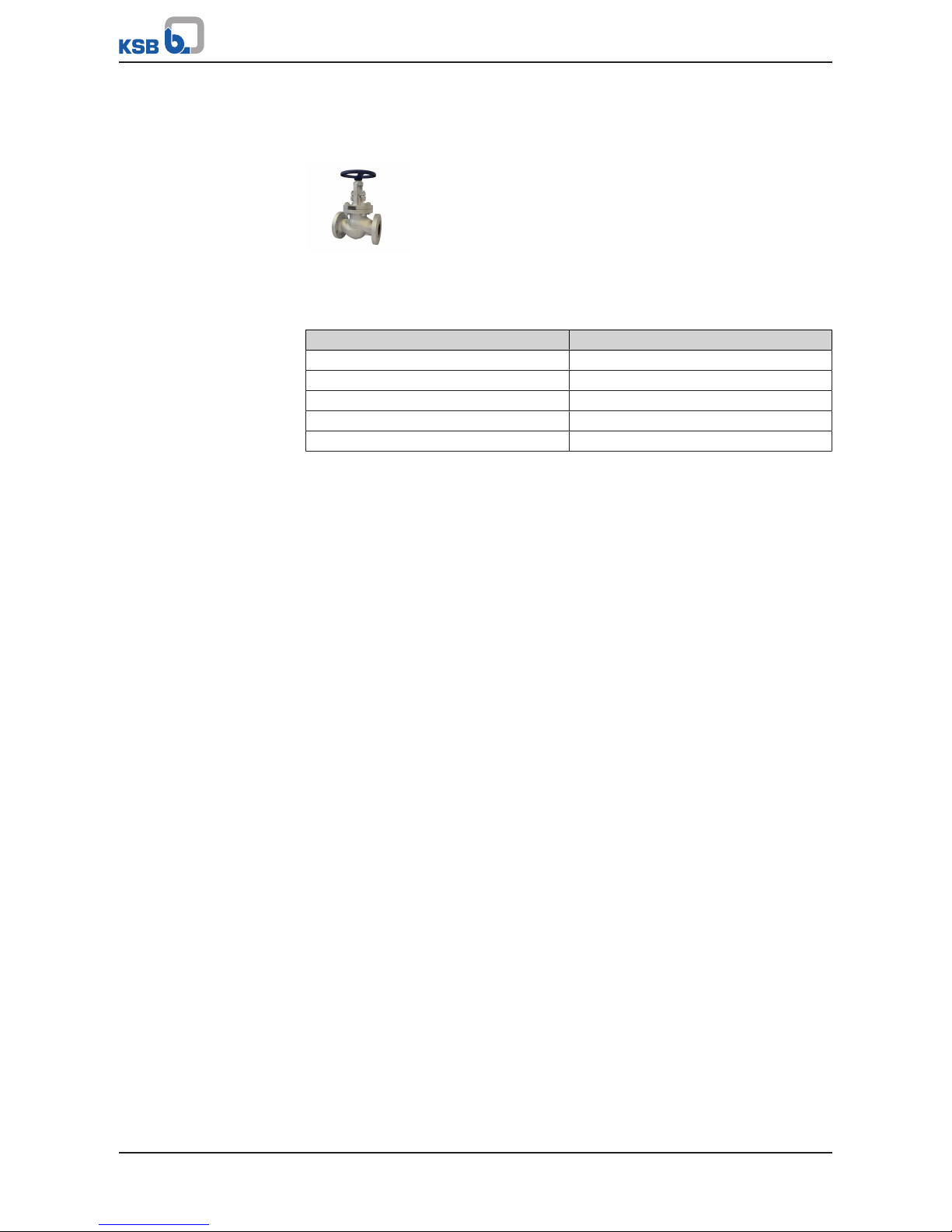
4.3 Globe Valves to ANSI/ASME with Gland Packing
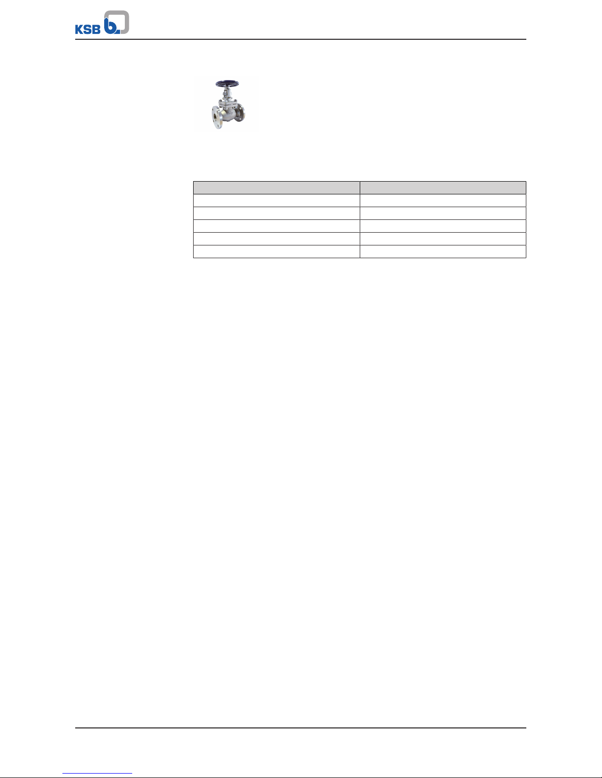
4.3.1 ECOLINE GLC 150-600
4.3.1.1 Operating data
Table5: Operating properties
Characteristic Value
Nominal pressure Class 150 - 600
Nominal size NPS 2'' - 12''
Max. permissible pressure 106 bar / 1500 PSI
Min. permissible temperature 0°C /32 °F
Max. permissible temperature 816 °C / 1500 °F
Temperatures < 0°C on request
Selection as per pressure/temperature ratings (ðSection4.3.1.4,Page16)
4.3.1.2 Fluids handled
▪ Steam
▪ Fluids containing gas
▪ Fluids containing mineral oils
▪ Gas
▪ High-temperature hot water
▪ Feed water
▪ Oil

4 Valve Description
15 of 100
4.3.1.3 Design details
Design
▪ Globe valve to BS 1873
▪ Tested to API 598
▪ Body made of cast steel or stainless steel
▪ Bolted bonnet
▪ Outside screw
▪ Rotating stem
▪ Non-rotating stem (8'' and 10'' Class 300/600)
▪ Rising stem
▪ Stem with burnished shank
▪ Solid flat disc (plug-type valve disc for 8" and 10" Class 600)
▪ Stem sealed by gland packing
▪ Two-piece self-aligning gland follower
▪ Stem nut made of nickel steel
▪ Valve seat made of wear-resistant and corrosion-proof materials
▪ Back seat
▪ Hardened back seat bush
▪ Die-moulded graphite gland packing, packing end rings made of braided
graphite
▪ Stainless steel/graphite gaskets
▪ Outside yoke
▪ Yoke head suitable for mounting electric and pneumatic actuators (DIN ISO 5210)
▪ The valves satisfy the safety requirements of Annex I of the European Pressure
Equipment Directive 97/23/EC (PED) for fluids in Groups 1 and 2.
▪ The valves do not have a potential internal source of ignition and can be used in
potentially explosive atmospheres, Group II, category2 (zones1+21) and
category3 (zones2+22) to ATEX 2014/34/EU.
Variants
▪ Position indicator
▪ Limit switch(es)
▪ Locking device
▪ Throttling plug
▪ Hard-faced back seat
▪ Drain plug
▪ Bypass
▪ Version in compliance with TA-Luft (German Clean Air Act) to VDI 2440 for
temperatures up to 400 °C
▪ Version with free stem end and top flange to ISO 5210
▪ Gearboxes
▪ Electric actuators
▪ Non-destructive testing, e.g. radiographic testing
▪ Inspections to technical codes such as AD2000 or IBR
▪ NACE standard
▪ Other flanged end designs or butt weld ends to ASME B16.25
▪ Larger nominal sizes and other variants on request
4 Valve Description
16 of 100
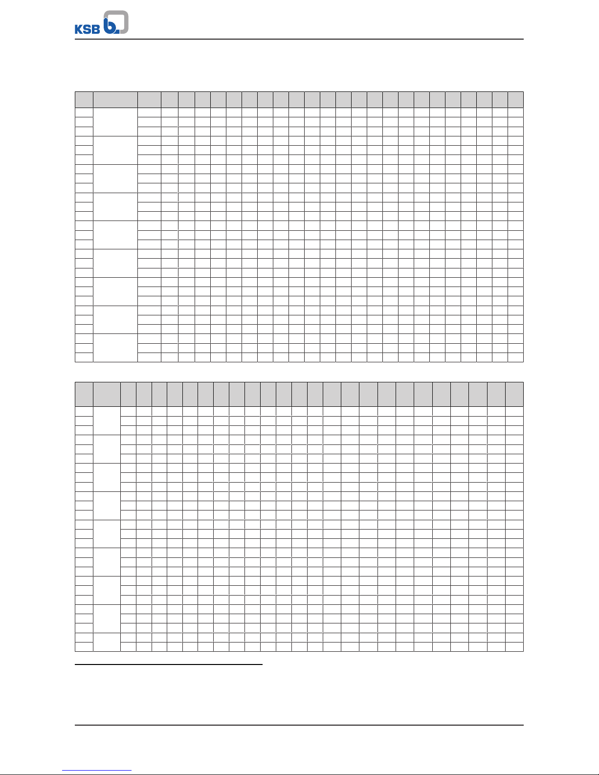
4.3.1.4 Pressure/temperature ratings
Table6: Permissible operating pressures in bar at temperatures in °C (to ASME B16.34)
Class
Material -29 to3893 149 204 260 316 343 371 399 427 454 482 510 538 566 593 621 649 677 704 732 760 788 816
150 A 216 WCB4)19,7 17,9 15,9 13,8 11,7 9,7 8,6 7,6 6,6 5,5 4,5 3,4 2,4 1,4 - - - - - - - - - 300 51,0 46,9 45,2 43,8 41,7 39,3 37,9 36,5 34,8 28,3 22,1 15,9 9,3 5,9 - - - - - - - - - 600 102,0 93,8 90,3 87,2 83,1 78,3 75,8 73,1 70,0 56,9 44,1 31,7 19,0 11,7 - - - - - - - - - 150 A 217 WC65)20,0 17,9 15,9 13,8 11,7 9,7 8,6 7,6 6,6 5,5 4,5 3,4 2,4 1,4 1,46)1,46)- - - - - - - 300 51,7 51,7 49,6 47,9 45,9 41,7 40,7 39,3 36,5 35,2 33,4 31,0 22,1 14,8 10,0 6,6 - - - - - - - 600 103,4 103,4 99,6 95,5 91,7 83,4 81,0 78,3 73,4 70,0 67,2 62,1 44,1 29,6 20,0 13,1 - - - - - - - 150 A 217 WC9 20,0 17,9 15,9 13,8 11,7 9,7 8,6 7,6 6,6 5,5 4,5 3,4 2,4 1,4 1,46)1,46)- - - - - - - 300 51,7 51,7 50,3 48,6 45,9 41,7 40,7 39,3 36,5 35,2 33,4 31,0 26,5 18,3 12,1 7,6 - - - - - - - 600 103,4 103,4 100,3 97,2 91,7 83,4 81,0 78,3 73,4 70,0 67,2 62,1 52,1 36,9 24,1 15,2 - - - - - - - 150 A 217 C5 20,0 17,9 15,9 13,8 11,7 9,7 8,6 7,6 6,6 5,5 4,5 3,4 2,4 1,4 1,46)1,46)1,46)1,06)- - - - - 300 51,7 51,7 50,3 48,6 45,9 41,7 40,7 39,3 36,5 35,2 33,4 25,9 19,0 13,8 10,0 6,9 4,1 2,4 - - - - - 600 103,4 103,4 100,3 97,2 91,7 83,4 81,0 78,3 73,4 70,0 67,2 51,4 37,9 27,6 20,0 13,8 8,6 4,8 - - - - - 150 A 217 C12 20,0 17,9 15,9 13,8 11,7 9,7 8,6 7,6 6,6 5,5 4,5 3,4 2,4 1,4 1,46)1,46)1,46)1,46)- - - - - 300 51,7 51,7 50,3 48,6 45,9 41,7 40,7 39,3 36,5 35,2 33,4 31,0 25,9 17,6 11,7 7,9 5,2 3,4 - - - - - 600 103,4 103,4 100,3 97,2 91,7 83,4 81,0 78,3 73,4 70,0 67,2 62,1 52,1 34,8 23,8 15,5 10,3 7,2 - - - - - 150 A 352 LCB7)18,3 17,6 15,9 13,8 11,7 9,7 8,6 - - - - - - - - - - - - - - - - 300 47,9 45,5 44,1 42,4 40,3 37,9 36,9 - - - - - - - - - - - - - - - - 600 96,2 91,0 87,9 84,8 81,0 76,2 73,4 - - - - - - - - - - - - - - - - 150 A 352 LCC 20,0 17,9 15,9 13,8 11,7 9,7 8,6 - - - - - - - - - - - - - - - - 300 51,7 51,7 50,3 48,6 45,9 41,7 40,7 - - - - - - - - - - - - - - - - 600 103,4 103,4 100,3 96,6 91,7 83,4 81,0 - - - - - - - - - - - - - - - - 150 A 351 CF88)19,0 15,9 14,1 13,1 11,7 9,7 8,6 7,6 6,6 5,5 4,5 3,4 2,4 1,4 1,46)1,46)1,46)1,46)1,46)1,46)1,46)1,46)1,46)1,0
6)
300 49,6 41,4 37,2 34,1 32,1 30,3 29,6 29,0 28,6 27,9 27,2 26,9 26,2 24,5 22,4 17,6 14,1 11,4 9,3 7,9 6,6 5,2 4,1 2,8
600 99,3 82,7 74,1 68,6 64,1 61,0 59,6 58,3 56,9 55,8 54,5 53,8 52,7 49,0 44,8 35,5 28,3 22,8 18,3 15,5 12,8 10,3 7,9 5,9
150 A 351 CF8M8)19,0 16,2 14,8 13,4 11,7 9,7 8,6 7,6 6,6 5,5 4,5 3,4 2,4 1,4 1,46)1,46)1,46)1,46)1,46)1,46)1,46)1,46)1,46)1,0
6)
300 49,6 42,7 38,6 35,5 33,1 31,0 30,3 30,0 29,3 29,0 29,0 28,6 26,5 25,2 24,8 21,0 16,2 12,8 10,0 7,9 6,6 5,2 4,1 2,8
600 99,3 85,5 77,2 70,7 65,8 62,1 61,0 60,0 59,0 58,3 57,6 57,2 53,4 50,0 49,6 42,1 32,8 25,5 20,3 16,2 13,1 10,3 7,9 5,9
Table7: Permissible operating pressures in PSI at temperatures in °F (to ASME B16.34)
Class
Material
-20
to
100
200 300 400 500 600 650 700 750 800 850 900 950 1000 1050 1100 1150 1200 1250 1300 1350 1400 1450 1500
150 A 216
WCB
4)
285 260 230 200 170 140 125 110 95 80 65 50 35 20 - - - - - - - - - 300 740 680 655 635 605 570 550 530 505 410 320 230 135 85 - - - - - - - - - 600 1480 1360 1310 1265 1205 1135 1100 1060 1015 825 640 460 275 170 - - - - - - - - - 150 A 217
WC6
5)
290 260 230 200 170 140 125 110 95 80 65 50 35 20 206)206)- - - - - - - 300 750 750 720 695 665 605 590 570 530 510 485 450 320 215 145 95 - - - - - - - 600 1500 1500 1445 1385 1330 1210 1175 1135 1065 1015 975 900 640 430 290 190 - - - - - - - 150 A 217
WC9
290 260 230 200 170 140 125 110 95 80 65 50 35 20 206)206)- - - - - - - 300 750 750 730 705 665 605 590 570 530 510 485 450 385 265 175 110 - - - - - - - 600 1500 1500 1455 1410 1330 1210 1175 1135 1065 1015 975 900 755 535 350 220 - - - - - - - 150 A 217 C5 290 260 230 200 170 140 125 110 95 80 65 50 35 20 206)206)206)156)- - - - - 300 750 750 730 705 665 605 590 570 530 510 485 375 275 200 145 100 60 35 - - - - - 600 1500 1500 1455 1410 1330 1210 1175 1135 1065 1015 975 745 550 400 290 200 125 70 - - - - - 150 A 217
C12
290 260 230 200 170 140 125 110 95 80 65 50 35 20 206)206)206)206)- - - - - 300 750 750 730 705 665 605 590 570 530 510 485 450 375 255 170 115 75 50 - - - - - 600 1500 1500 1455 1410 1330 1210 1175 1135 1065 1015 975 900 755 505 345 225 150 105 - - - - - 150 A 352
LCB
7)
265 255 230 200 170 140 125 - - - - - - - - - - - - - - - - 300 695 660 640 615 585 550 535 - - - - - - - - - - - - - - - - 600 1395 1320 1275 1230 1175 1105 1065 - - - - - - - - - - - - - - - - 150 A 352
LCC
290 260 230 200 170 140 125 - - - - - - - - - - - - - - - - 300 750 750 730 705 665 605 590 - - - - - - - - - - - - - - - - 600 1500 1500 1455 1405 1330 1210 1175 - - - - - - - - - - - - - - - - 150 A 351
CF8
8)
275 230 205 190 170 140 125 110 95 80 65 50 35 20 206)206)206)206)206)206)206)206)206)15
6)
300 720 600 540 495 465 440 430 420 415 405 395 390 380 355 325 255 205 165 135 115 95 75 60 40
600 1440 1200 1075 995 930 885 865 845 825 810 790 780 765 710 650 515 410 330 265 225 185 150 115 85
150 A 351
CF8M
8)
275 235 215 195 170 140 125 110 95 80 65 50 35 20 206)206)206)206)206)206)206)206)206)15
6)
300 720 620 560 515 480 450 440 435 425 420 420 415 385 365 360 305 235 185 145 115 95 75 60 40
4) Permissible but not recommended for prolonged use above 427°C (800°F).
5) Cannot be used for temperatures above 593°C (1100°F).
6) For butt weld end valves only. Flanged end ratings terminate at 538°C (1000°F).
7) Cannot be used for temperatures above 343°C (650°F).
8) At temperatures over 538°C (1000°F), use only when carbon content is 0.04% or higher.
4 Valve Description
17 of 100
Class
Material
-20
to
100
200 300 400 500 600 650 700 750 800 850 900 950 1000 1050 1100 1150 1200 1250 1300 1350 1400 1450 1500
600 1440 1240 1120 1025 955 900 885 870 855 845 835 830 775 725 720 610 475 370 295 235 190 150 115 85
Table8: Test pressures
Test Test medium Class 150 Class 300 Class 600
[bar] [psi] [bar] [psi] [bar] [psi]
Shell Water 32 450 78 1125 153 2225
Leak test (back seat) 23 315 56 815 112 1630
Leak test (seat) 23 315 56 815 112 1630
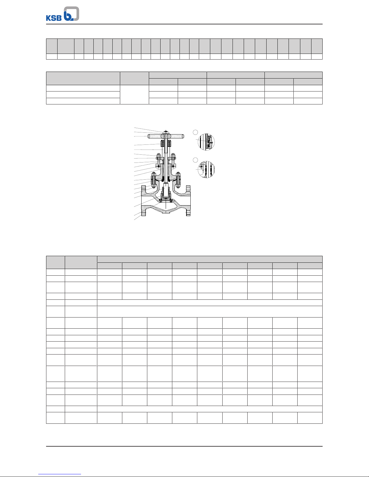
4.3.1.5 Materials
1
2
920.3
920.1
411
166
900
465
450
461
560
452
920.2
544
961
554
458
300
100
515
350
200
902
① Bearing (8''-12'' Class 300, 6''-12'' Class 600)
② Lantern ring (optional)
Table9: Parts list
Part
No.
Description Material
A 216 WCB A 217 WC6 A 217 WC9 A 217 C5 A 217 C12 A 352 LCB A 352 LCC A 351 CF8 A 351 CF8M
100 Body A 216 WCB A 217 WC6 A 217 WC9 A 217 C5 A 217 C12 A352 LCB A 352 LCC A 351 CF8 A 351 CF8M
166 Yoke A 216 WCB A 217 WC6 A 217 WC9 A 217 C5 A 217 C12 A352 LCB A 352 LCC A 351 CF8 A 351 CF8M
350 Lower valve disc
section
A 216 WCB A 217 WC6 A 217 WC9 A 217 C5 A 217 C12 A352 LCB A 352 LCC A 351 CF8 A 351 CF8M
515 Seat ring A 105 A 182 F11 A 182 F22 A 182 F5 A 182 F9 A 182 LF2 A 350 LF2 A 182 F304 A 182 F316
200 Stem See "Trim materials" table
450 Back seat
bush
See "Trim materials" table
465 Lower gland
section
13Cr 13Cr 13Cr 13Cr 13Cr 304 304 304 316
452 Gland follower A 216 WCB A 216 WCB A 216 WCB A 351 CF8 A 351 CF8 A 351 CF8 A 351 CF8 A 351 CF8 A 351 CF8
544 Threaded bush A 439 D2C A 439 D2C A 439 D2C A 439 D2C A 439 D2C A 439 D2C A 439 D2C A 439 D2C A 439 D2C
902 Stud A 193 B7 A 193 B16 A 193 B16 A 193 B16 A 193 B16 A 320 L7 A 320 L7 A 193 B8 A 193 B8
920.1 Nut A 194 2H A 194 Gr. 7 A 194 Gr. 7 A 194 Gr. 7 A 194 Gr. 7 A 194 Gr. 7 A 194 Gr. 7 A 194 Gr. 8 A 194 Gr. 8
461 Gland
packing
Graphite Graphite Graphite Graphite Graphite Graphite Graphite Graphite Graphite
411 Joint ring Graphite +
stainless
steel
Graphite +
stainless
steel
Graphite +
stainless
steel
Graphite +
stainless
steel
Graphite +
stainless
steel
Graphite +
stainless
steel
Graphite +
stainless
steel
Graphite +
stainless
steel
Graphite +
stainless
steel
900 Eyebolt A 307 B A 193 B16 A 193 B16 A 193 B16 A 193 B16 A 320 L7 A 320 L7 A 193 B8 A 193 B8
920.2 Nut A 194 2H A 194 Gr. 7 A 194 Gr. 7 A 194 Gr. 7 A 194 Gr. 7 A 194 Gr. 7 A 194 Gr. 7 A 194 Gr. 8 A 194 Gr. 8
560 Pin Carbon
steel
Carbon
steel
Carbon
steel
Carbon
steel
Carbon
steel
Carbon steel Carbon
steel
Stainless
steel
Stainless
steel
961 Handwheel Nodular cast iron or malleable cast iron or cast steel
920.3 Handwheel nut Carbon
steel
Carbon
steel
Carbon
steel
Carbon
steel
Carbon
steel
Carbon
steel
Carbon
steel
Stainless
steel
Stainless
steel

4 Valve Description
18 of 100
Part
No.
Description Material
A 216 WCB A 217 WC6 A 217 WC9 A 217 C5 A 217 C12 A 352 LCB A 352 LCC A 351 CF8 A 351 CF8M
554 Washer Carbon
steel
Carbon
steel
Carbon
steel
Carbon
steel
Carbon
steel
Carbon
steel
Carbon
steel
Stainless
steel
Stainless
steel
300 Bearing Steel Steel Steel Steel Steel Steel Steel Steel Steel
458 Lantern ring 13Cr 13Cr 13Cr 13Cr 13Cr 304 304 304 316
Table10: Trim materials
Part No. Description Trim 1 Trim 2 Trim 5 Trim 8 Trim 10
13% chrome steel (Cr) /
13% chrome steel (Cr)
304 / 304 Stellite / Stellite Stellite / 13% chrome
steel (Cr)
316 / 316
350 Lower valve disc
section
13% chrome steel (Cr) 304 stainless steel Stellite 13% chrome steel (Cr) 316 stainless steel
515 Seat ring 13% chrome steel (Cr) 304 stainless steel Stellite Stellite 316 stainless steel
200 Stem 13% chrome steel (Cr) 304 stainless steel 13% chrome steel (Cr) 13% chrome steel (Cr) 316 stainless steel
450 Back seat
bush
13% chrome steel (Cr) 304 stainless steel 13% chrome steel (Cr) 13% chrome steel (Cr) 316 stainless steel
4.3.1.6 Function
The main components of the globe valves are the body (100), the yoke (166), the
valve disc (350), the stem (200) and the actuating unit.
Stem seal
The gland packing (461), which seals off the stem (200), is tightened via the gland
follower (452) by means of eyebolts (900) and nuts (920.2). The yoke (166) is
equipped with a back seat bush (450) which seals off the valve when the stem (200) is
fully retracted.
Seat/disc interface
The hard-faced seat ring (515) is welded into the body (100). The seating surface of
the valve disc (350) is hard-faced.
Bonnet/cover seal
The body (100) and the yoke (166) are connected by studs (902) and nuts (920.1). The
joint is sealed by means of a joint ring (411).
4.3.2 ECOLINE GLF 150-600
4.3.2.1 Operating data
Table11: Operating properties
Characteristic Value
Nominal pressure Class 150 - 600
Nominal size NPS ½'' - 2''
Max. permissible pressure 104 bar / 1480 PSI
Min. permissible temperature 0°C /32 °F
Max. permissible temperature 816 °C / 1500 °F
Temperatures < 0°C on request
Selection as per pressure/temperature ratings (ðSection4.3.2.4,Page20)

4 Valve Description
19 of 100
4.3.2.2 Fluids handled
▪ Steam
▪ Fluids containing gas
▪ Gas
▪ High-temperature hot water
▪ Fluids containing mineral oils
▪ Oil
▪ Feed water
4.3.2.3 Design details
Design
▪ Globe valve to API 602
▪ Tested to API 598
▪ Body made of forged steel
▪ Bolted bonnet
▪ Outside screw
▪ Outside yoke
▪ Rotating stem
▪ Rising handwheel
▪ Stem sealed by gland packing
▪ Reduced bore
▪ Two-piece self-aligning gland follower
▪ Graphite gland packing
▪ Stem with burnished shank
▪ Fully confined bonnet gasket
▪ Back seat
▪ Solid valve disc
▪ Integral seat - ST6 (HF)
▪ The valves satisfy the safety requirements of Annex I of the European Pressure
Equipment Directive 97/23/EC (PED) for fluids in Groups 1 and 2.
▪ The valves do not have a potential internal source of ignition and can be used in
potentially explosive atmospheres, Group II, category2 (zones1+21) and
category3 (zones2+22) to ATEX 2014/34/EU.
Variants
▪ Seal-welded body/bonnet joint
▪ Full bore
▪ Hard-faced back seat
▪ Extended bonnet
▪ Locking device
▪ Position indicator
▪ Electric actuators
▪ Version in compliance with TA-Luft (German Clean Air Act) to VDI 2440 for
temperatures up to 400 °C
▪ Butt weld ends
▪ NACE standard
▪ Other flanged end designs or butt weld ends to ASME B16.25
▪ Other trims
4 Valve Description
20 of 100
4.3.2.4 Pressure/temperature ratings
Table12: Permissible operating pressures in bar at temperatures in °C (to ASME B16.34)
Class
Material 0 to 38 93 149 204 260 316 343 371 399 427 454 482 510 538 566 593 621 649 677 704 732 760 788 816
150 A 105 19,7 17,9 15,9 13,8 11,7 9,7 8,6 7,6 6,6 5,5 - - - - - - - - - - - - - 300 51,0 46,9 45,2 43,8 41,7 39,3 37,9 36,5 34,8 28,3 - - - - - - - - - - - - - 600 102,0 93,8 90,3 87,2 83,1 78,3 75,8 73,1 70,0 56,9 - - - - - - - - - - - - - 150 A 182 F11 9)20,0 17,9 15,9 13,8 11,7 9,7 8,6 7,6 6,6 5,5 4,5 3,4 2,4 1,4 1,4
10)
1,4
10)
- - - - - - - 300 51,7 51,7 49,6 47,9 45,9 41,7 40,7 39,3 36,5 35,2 33,4 31,0 22,1 14,8 10,0 6,6 - - - - - - - 600 103,4 103,4 99,6 95,5 91,7 83,4 81,0 78,3 73,4 70,0 67,2 62,1 44,1 29,6 20,0 13,1 - - - - - - - 150 A 182 F304
11)
19,0 15,9 14,1 13,1 11,7 9,7 8,6 7,6 6,6 5,5 4,5 3,4 2,4 1,4 1,4
10)
1,4
10)
1,4
10)
1,4
10)
1,4
10)
1,4
10)
1,4
10)
1,4
10)
1,4
10)
1,0
10)
300 49,6 41,4 37,2 34,1 32,1 30,3 29,6 29,0 28,6 27,9 27,2 26,9 26,2 24,5 22,4 17,6 14,1 11,4 9,3 7,9 6,6 5,2 4,1 2,8
600 99,3 82,7 74,1 68,6 64,1 61,0 59,6 58,3 56,9 55,8 54,5 53,8 52,7 49,0 44,8 35,5 28,3 22,8 18,3 15,5 12,8 10,3 7,9 5,9
150 A 182 F22 20,0 17,9 15,9 13,8 11,7 9,7 8,6 7,6 6,6 5,5 4,5 3,4 2,4 1,4 1,4
10)
1,4
10)
- - - - - - - 300 51,7 51,7 50,3 48,6 45,9 41,7 40,7 39,3 36,5 35,2 33,4 31,0 26,5 18,3 12,1 7,6 - - - - - - - 600 103,4 103,4 100,3 97,2 91,7 83,4 81,0 78,3 73,4 70,0 67,2 62,1 52,1 36,9 24,1 15,2 - - - - - - - 150 A 182 F316
11)
19,0 16,2 14,8 13,4 11,7 9,7 8,6 7,6 6,6 5,5 4,5 3,4 2,4 1,4 1,4
10)
1,4
10)
1,4
10)
1,4
10)
1,4
10)
1,4
10)
1,4
10)
1,4
10)
1,4
10)
1,0
10)
300 49,6 42,7 38,6 35,5 33,1 31,0 30,3 30,0 29,3 29,0 29,0 28,6 26,5 25,2 24,8 21,0 16,2 12,8 10,0 7,9 6,6 5,2 4,1 2,8
600 99,3 85,5 77,2 70,7 65,8 62,1 61,0 60,0 59,0 58,3 57,6 57,2 53,4 50,0 49,6 42,1 32,8 25,5 20,3 16,2 13,1 10,3 7,9 5,9
150 A 182 F304L 15,9 13,4 12,1 11,0 10,3 9,7 8,6 7,6 7,6 5,5 - - - - - - - - - - - - - 300 41,4 35,2 31,4 30,0 27,2 25,5 25,2 24,8 24,5 23,8 - - - - - - - - - - - - - 600 82,7 70,3 62,7 57,9 54,1 51,4 50,3 49,6 48,6 47,6 - - - - - - - - - - - - - 150 A 182 F316L 15,9 13,4 12,1 11,0 10,3 9,7 8,6 7,6 7,6 5,5 4,5 - - - - - - - - - - - - 300 41,4 35,2 31,4 29,0 27,2 25,5 25,2 24,8 24,5 23,8 23,4 - - - - - - - - - - - - 600 82,7 70,3 62,7 57,9 54,1 51,4 50,3 49,6 48,6 47,6 46,5 - - - - - - - - - - - - -
Table13: Permissible operating pressures in PSI at temperatures in °F (to ASME B16.34)
Class
Material
32
to
100
200 300 400 500 600 650 700 750 800 850 900 950 1000 1050 1100 1150 1200 1250 1300 1350 1400 1450 1500
150 A 105 285 260 230 200 170 140 125 110 95 80 - - - - - - - - - - - - - 300 740 680 655 635 605 570 550 530 505 410 - - - - - - - - - - - - - 600 1480 1360 1310 1265 1205 1135 1100 1060 1015 825 - - - - - - - - - - - - - 150 A 182
F11
9)
290 260 230 200 170 140 125 110 95 80 65 50 35 20 20
10)
20
10)
- - - - - - - 300 750 750 720 695 665 605 590 570 530 510 485 450 320 215 145 95 - - - - - - - 600 1500 1500 1445 1385 1330 1210 1175 1135 1065 1015 975 900 640 430 290 190 - - - - - - - 150 A 182
F304
11)
275 230 205 190 170 140 125 110 95 80 65 50 35 20 20
10)
20
10)
20
10)
20
10)
20
10)
20
10)
20
10)
20
10)
20
10)
15
10)
300 720 600 540 495 465 440 430 420 415 405 395 390 380 355 325 255 205 165 135 115 95 75 60 40
600 1440 1200 1075 995 930 885 865 845 825 810 790 780 765 710 650 515 410 330 265 225 185 150 115 85
150 A 182
F22
290 260 230 200 170 140 125 110 95 80 65 50 35 20 20
10)
20
10)
- - - - - - - 300 750 750 730 705 665 605 590 570 530 510 485 450 385 265 175 110 - - - - - - - 600 1500 1500 1455 1410 1330 1210 1175 1135 1065 1015 975 900 755 535 350 220 - - - - - - - 150 A 182
F316
11)
275 235 215 195 170 140 125 110 95 80 65 50 35 20 20
10)
20
10)
20
10)
20
10)
20
10)
20
10)
20
10)
20
10)
20
10)
15
10)
300 720 620 560 515 480 450 440 435 425 420 420 415 385 365 360 305 235 185 145 115 95 75 60 40
600 1440 1240 1120 1025 955 900 885 870 855 845 835 830 775 725 720 610 475 370 295 235 190 150 115 85
150 A 182
F304L
230 195 175 160 150 140 125 110 110 80 - - - - - - - - - - - - - 300 600 510 455 420 395 370 365 360 355 345 - - - - - - - - - - - - - 600 1200 1020 910 840 785 745 730 720 705 690 - - - - - - - - - - - - - 150 A 182
F316L
230 195 175 160 150 140 125 110 110 80 65 - - - - - - - - - - - - 300 600 510 455 420 395 370 365 360 355 345 340 - - - - - - - - - - - - 600 1200 1020 910 840 785 745 730 720 705 690 675 - - - - - - - - - - - - -
Table14: Test pressures
Test Test medium Class 150 Class 300 Class 600
[bar] [psi] [bar] [psi] [bar] [psi]
Shell Water 31,0 450 77,6 1125 153,4 2225
Leak test (back seat) 22,4 325 56,9 825 113,8 1650
Leak test (seat) 22,4 325 56,9 825 113,8 1650
Leak test (seat) Air 5,5 80 5,5 80 5,5 80
9) Use normalised and tempered materials only.
10) Flanged end ratings terminate at 538°C (1000°F).
11) At temperatures over 538°C (1000°F), use only when carbon content is 0.04% or higher.
4 Valve Description
21 of 100
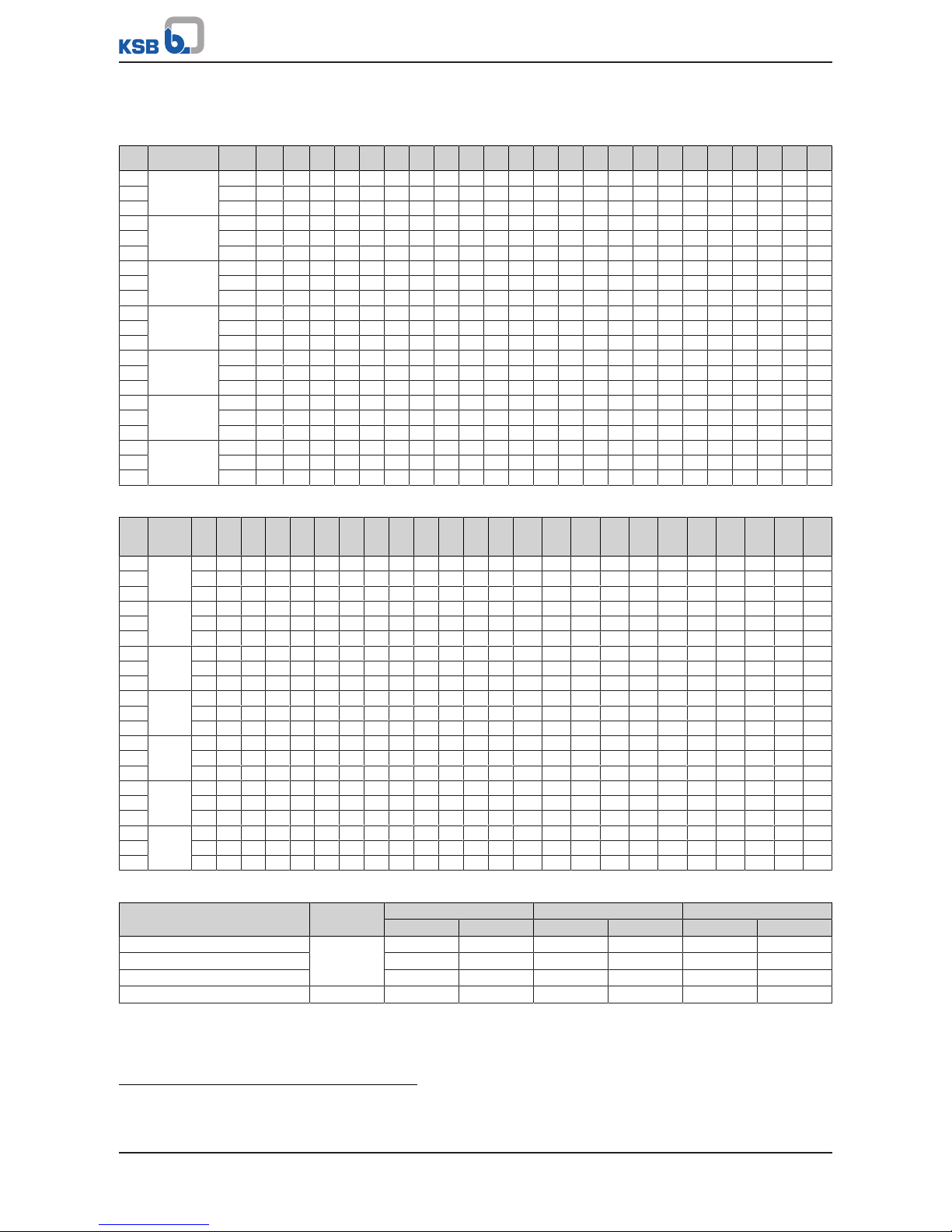
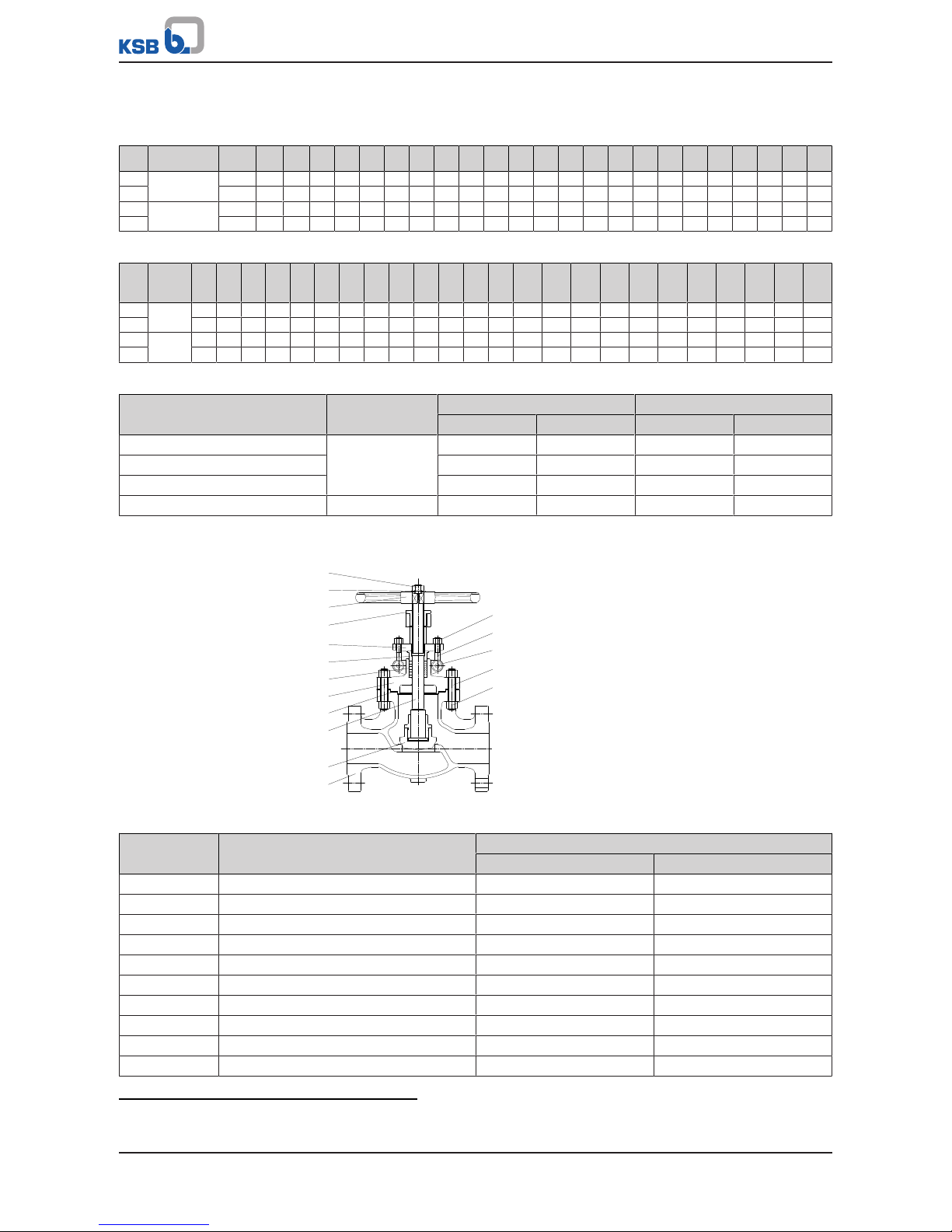
4.3.2.5 Materials
961
544
920
452
465
902
461
901
166
411
200
350
515
100
1
① Tack-welded
Table15: Parts list
Part No.
Description Material
A 105
Trim 8
A 182 F11
Trim 5
A 182 F22
Trim 5
A 182 F304
Trim 2
A 182 F316
Trim 10
100 Body A 105 A 182 F11 A 182 F22 A 182 F304 A 182 F316
166 Yoke A 105 A 182 F11 A 182 F22 A 182 F304 A 182 F316
200 Stem A 182 F6a A 182 F6a A 182 F6a A 182 F304 A 182 F316
350 Valve disc A 182 F6a A 182 F6a + STL6 A 182 F6a + STL6 A 182 F304 A 182 F316
411 Joint ring 304 + graphite 304 + graphite 304 + graphite 304 + graphite 316 + graphite
452 Gland follower A 105 A 105 A 105 A 182 F304 A 182 F316
465 Lower gland
section
A 276 410 A 276 410 A 276 410 A 276 304 A 276 316
461 Gland packing Flexible graphite Flexible graphite Flexible graphite Flexible graphite Flexible graphite
515 Seat ring STL6 (integral) STL6 (integral) STL6 (integral) 304 (integral) 316 (integral)
544 Threaded bush A 276 410 A 276 410 A 276 410 A 276 410 A 276 410
901 Bolt A 193 B7 A 193 B16 A 193 B16 A 193 B8 A 193 B8M
902 Stud A 193 B8 A 193 B16 A 193 B16 A 193 B8 A 193 B8
920 Nut A 194 2H A 194 8 A 194 8 A 194 8 A 194 8M
961 Handwheel A 197 A 197 A 197 A 197 A 197
4.3.2.6 Function
The main components of the globe valves are the body (100), the yoke (166), the
valve disc (351), the stem (200) and the actuating unit.
Stem seal
The gland packing (461), which seals off the stem (200), is tightened via the gland
follower (452) by means of studs (902) and nuts (920). The yoke (166) features an
integral back seat which seals off the valve when the stem (200) is fully retracted.
Seat/disc interface
The integral seating surfaces in the body (100) are hard-faced. The valve disc (351) is
connected to the stem (200) by a "T" joint.
Bonnet/cover seal
The yoke (166) is bolted to the body (100). The joint is sealed by a joint ring (411).
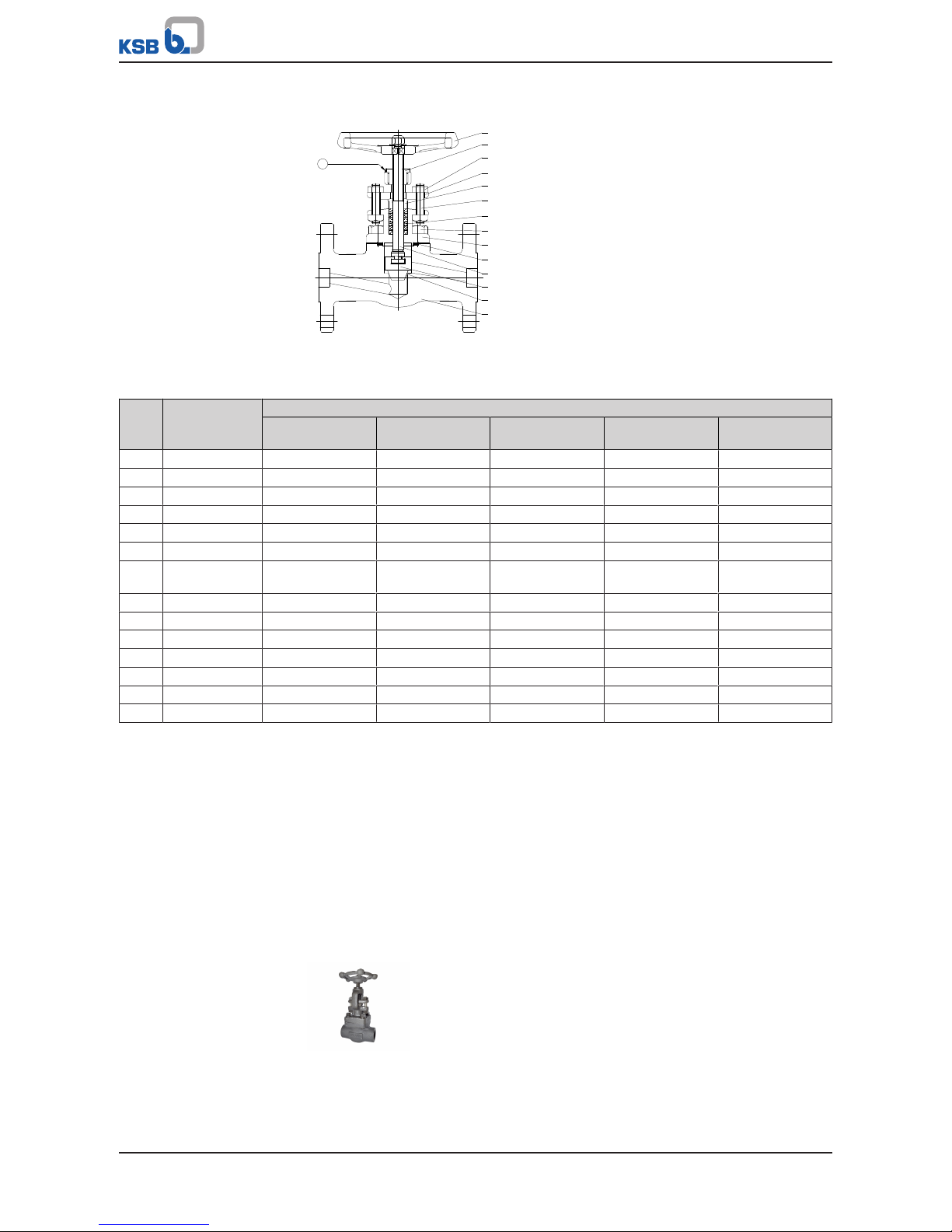
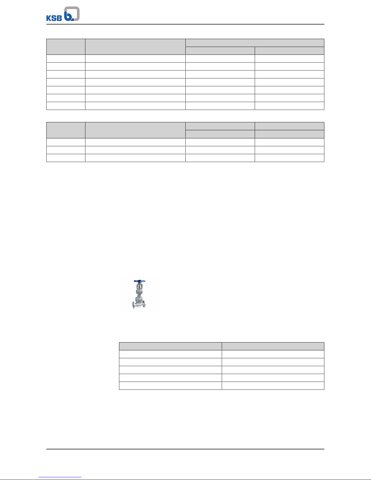
4.3.3 ECOLINE GLF 800-2500

4 Valve Description
22 of 100
4.3.3.1 Operating data
Table16: Operating properties
Characteristic Value
Nominal pressure Class 800 - 2500
Nominal size NPS ½" - 2"
Max. permissible pressure 431 bar / 6250 PSI
Min. permissible temperature 0°C /32 °F
Max. permissible temperature +538 °C / +1500 °F
Temperatures < 0°C on request
Selection as per pressure/temperature ratings (ðSection4.3.3.4,Page24)
4.3.3.2 Fluids handled
▪ Steam
▪ Fluids containing gas
▪ Gas
▪ High-temperature hot water
▪ Fluids containing mineral oils
▪ Oil
▪ Feed water
4.3.3.3 Design details
Design
▪ Globe valve to API 602
▪ Tested to API 598
▪ Body made of forged steel
▪ Bolted bonnet (Class 800)
▪ Welded bonnet
▪ Outside screw
▪ Outside yoke
▪ Rotating stem
▪ Rising handwheel
▪ Stem sealed by gland packing
▪ Reduced bore
▪ Two-piece self-aligning gland follower
▪ Graphite gland packing
▪ Stem with burnished shank
▪ Fully confined bonnet gasket (Class 800)
▪ Back seat
▪ Solid valve disc
▪ Integral seat - ST6 (HF)
▪ The valves satisfy the safety requirements of Annex I of the European Pressure
Equipment Directive 97/23/EC (PED) for fluids in Groups 1 and 2.
▪ The valves do not have a potential internal source of ignition and can be used in
potentially explosive atmospheres, Group II, category2 (zones1+21) and
category3 (zones2+22) to ATEX 2014/34/EU.

4 Valve Description
23 of 100
Variants
▪ Full bore
▪ Hard-faced back seat
▪ Extended bonnet
▪ Locking device
▪ Position indicator
▪ Electric actuators
▪ Version in compliance with TA-Luft (German Clean Air Act) to VDI 2440 for
temperatures up to 400 °C
▪ Butt weld ends
▪ NACE standard
▪ Other threaded ends or butt weld ends to ASME B16.25
▪ Other trims
▪ Other material variants
4 Valve Description
24 of 100
4.3.3.4 Pressure/temperature ratings
Table17: Permissible operating pressures in bar at temperatures in °C (to ASME B16.34)
Class
Material
0 to3893 149 204 260 316 343 371 399 427 454 482 510 538 566 593 621 649 677 704 732 760 788 816
800 A 105 136,0 124,8 120,5 116,4 110,9 104,5 101,1 97,4 93,2 75,7 - - - - - - - - - - - - - 1500 255,3 233,0 225,4 219,0 209,7 193,6 187,8 181,8 173,6 143,8 - - - - - - - - - - - - - 2500 425,5 388,3 375,6 365,0 349,5 322,6 313,0 303,1 289,3 239,7 - - - - - - - - - - - - - 800 A 182
F11
12)
137,9 137,9 132,7 127,4 122,2 111,2 108,1 104,5 97,8 93,4 89,5 82,7 58,6 39,8 26,4 17,7 - - - - - - - 1500 258,6 257,4 248,7 239,8 231,8 206,6 201,1 194,1 183,1 175,1 169,0 158,2 128,6 74,5 44,0 30,5 - - - - - - - 2500 430,9 429,0 414,5 399,6 386,2 344,3 335,3 323,2 304,9 291,6 281,8 263,9 214,4 124,1 73,4 50,9 - - - - - - - 800 A 182 F22 137,9 137,9 133,9 129,6 122,2 111,2 108,1 104,5 97,8 93,4 89,5 82,7 70,7 49,1 32,2 20,2 - - - - - - - 1500 258,6 257,6 250,8 243,4 231,8 206,6 201,1 194,1 183,1 175,1 169,0 158,2 140,9 92,2 52,6 34,4 - - - - - - - 2500 430,9 429,4 418,2 405,4 386,2 344,3 335,3 323,2 304,9 291,6 281,8 263,9 235,0 153,7 87,7 57,4 - - - - - - - 800 A 182
F304
13)
132,4 110,3 98,9 91,4 85,5 81,2 79,4 77,6 76,0 74,5 72,9 71,5 70,2 65,3 59,8 47,2 37,7 30,3 24,5 20,8 17,1 13,8 10,7 7,7
1500 248,2 204,3 185,0 172,4 162,4 151,1 148,1 145,2 142,2 140,0 137,0 134,7 132,4 122,1 104,2 84,4 68,9 56,3 46,7 40,1 33,8 28,9 17,4 14,1
2500 413,7 340,4 308,4 287,3 270,7 251,9 246,9 241,9 237,0 233,3 228,4 224,5 220,7 203,6 173,7 140,7 114,9 93,8 77,9 66,9 56,3 48,1 29,2 23,8
800 A 182
F316
13)
132,4 114,0 102,9 94,3 87,9 82,9 81,2 80,0 78,5 77,6 76,9 76,3 71,2 66,7 66,2 56,1 43,6 34,0 27,0 21,5 17,7 13,8 10,7 7,7
1500 248,2 211,0 192,5 178,3 166,9 154,4 151,6 149,4 147,2 145,7 144,2 143,4 140,9 125,5 119,7 99,5 79,1 63,3 51,6 41,9 34,9 29,3 17,4 14,1
2500 413,7 351,6 320,8 297,2 278,1 257,4 252,7 249,0 245,3 242,9 240,4 238,9 235,0 208,9 199,5 165,9 131,8 105,5 86,0 69,8 58,2 48,9 29,2 23,8
800 A 182
F304L
110,3 94,0 83,9 77,2 72,3 68,4 67,1 66,2 64,9 63,4 - - - - - - - - - - - - - 1500 206,8 173,9 157,0 145,8 137,3 127,4 125,4 123,8 121,5 119,3 - - - - - - - - - - - - - 2500 344,7 289,9 261,6 243,0 228,9 212,3 208,9 206,3 202,5 198,8 - - - - - - - - - - - - - 800 A 182
F316L
110,3 94,0 83,9 77,2 72,3 68,4 67,1 66,2 64,9 63,4 62,2 - - - - - - - - - - - - 1500 206,8 173,9 157,0 145,8 137,3 127,4 125,4 123,8 121,5 119,3 117,1 - - - - - - - - - - - - 2500 344,7 289,9 261,6 243,0 228,9 212,3 208,9 206,3 202,5 198,8 195,1 - - - - - - - - - - - - 1500 A 182 F91 258,6 257,6 250,8 243,4 231,8 206,6 201,1 194,1 183,1 175,1 169,0 158,2 140,9 125,5 119,7 97,5 73,0 49,6 - - - - - 2500 430,9 429,4 418,2 405,4 386,2 344,3 335,3 323,2 304,9 291,6 281,8 263,9 235,0 208,9 199,5 162,5 121,7 82,7 - - - - - -
Table18: Permissible operating pressures in PSI at temperatures in °F (to ASME B16.34)
Class
Material
32
to
100
200 300 400 500 600 650 700 750 800 850 900 950 1000 1050 1100 1150 1200 1250 1300 1350 1400 1450 1500
800 A 105 1973 1810 1747 1688 1608 1515 1467 1413 1352 1098 - - - - - - - - - - - - - 1500 3705 3395 3270 3170 3015 2840 2745 2665 2535 2055 - - - - - - - - - - - - - 2500 6170 5655 5450 5280 5025 4730 4575 4425 4230 3430 - - - - - - - - - - - - - 800 A 182
F11
12)
2000 2000 1925 1848 1773 1613 1568 1515 1418 1355 1298 1200 850 577 383 257 - - - - - - - 1500 3750 3750 3610 3465 3325 3025 2940 2840 2660 2540 2435 2245 1595 1080 720 480 - - - - - - - 2500 6250 6250 6015 5775 5540 5040 4905 4730 4430 4230 4060 3745 2655 1800 1200 800 - - - - - - - 800 A 182
F22
2000 2000 1942 1880 1773 1613 1568 1515 1418 1355 1298 1200 1025 712 467 293 - - - - - - - 1500 3750 3750 3640 3530 3325 3025 2940 2840 2660 2540 2435 2245 1930 1335 875 550 - - - - - - - 2500 6250 6250 6070 5880 5540 5040 4905 4730 4430 4230 4060 3745 3220 2230 1455 915 - - - - - - - 800 A 182
F304
13)
1920 1600 1435 1325 1240 1178 1152 1125 1102 1080 1057 1037 1018 947 867 685 547 440 355 302 248 200 155 112
1500 3600 3000 2690 2485 2330 2210 2160 2110 2065 2030 1980 1945 1910 1770 1630 1285 1030 825 670 565 465 380 290 205
2500 6000 5000 4480 4140 3880 3680 3600 3520 3440 3380 3300 3240 3180 2950 2715 2145 1715 1370 1115 945 770 630 485 345
800 A 182
F316
13)
1920 1653 1493 1368 1275 1203 1178 1160 1138 1125 1115 1107 1032 968 960 813 632 493 392 312 257 200 155 112
1500 3600 3095 2795 2570 2390 2255 2210 2170 2135 2110 2090 2075 1930 1820 1800 1525 1185 925 735 585 480 380 290 205
2500 6000 5160 4660 4280 3980 3760 3680 3620 3560 3520 3480 3460 3220 3030 3000 2545 1970 1545 1230 970 800 630 485 345
800 A 182
F304L
1600 1363 1217 1120 1048 992 973 960 942 920 - - - - - - - - - - - - - 1500 3000 2555 2280 2100 1970 1860 1825 1800 1765 1730 - - - - - - - - - - - - - 2500 5000 4260 3800 3500 3280 3100 3040 3000 2940 2880 - - - - - - - - - - - - - 800 A 182
F316L
1600 1363 1217 1120 1048 992 973 960 942 920 902 - - - - - - - - - - - - 1500 3000 2555 2280 2100 1970 1860 1825 1800 1765 1730 1690 - - - - - - - - - - - - 2500 5000 4260 3800 3500 3280 3100 3040 3000 2940 2880 2820 - - - - - - - - - - - - 1500 A 182
F91
3750 3750 3640 3530 3325 3025 2940 2840 2660 2540 2435 2245 1930 1820 1800 1510 1115 720 - - - - - 2500 6250 6250 6070 5880 5540 5040 4905 4730 4430 4230 4060 3745 3220 3030 3000 2515 1855 1200 - - - - - -
12) Use normalised and tempered materials only.
13) At temperatures over 538°C (1000°F), use only when carbon content is 0.04% or higher.

4 Valve Description
25 of 100
Table19: Test pressures
Test Test medium Class 800 Class 1500 Class 2500
[bar] [psi] [bar] [psi] [bar] [psi]
Shell Water 205,1 2975 396 5625 660 9375
Leak test (back seat) 149,8 2173 291 4125 484 6875
Leak test (seat) 149,8 2173 291 4125 484 6875
Optional leak test (seat) Air 5,5 80 4 to 7 58 to 100 4 to 7 58 to 100
4 Valve Description
26 of 100
4.3.3.5 Materials
Class 800 Class 1500 Class 2500
1
961
544
920
452
465
902
461
901
166
411
200
350
515
100
1
2
961
544
920.3
920.2
452
465
900
560
461
166
200
350
515
100
1
2
961
544
920.3
920.2
452
465
900
920.2
461
166
200
350
515
100
① Tack-welded
② Seal-welded
Table20: Parts list
Part No.
Description Class Material
A 105
Trim 8
A 182 F11
Trim 5
A 182 F22
Trim 5
A 182 F304
Trim 2
A 182 F316
Trim 10
A182F91
Trim 5
100 Body A 105 A 182 F11 A 182 F22 A 182 F304 A 182 F316 A 182 F91
166 Yoke A 105 A 182 F11 A 182 F22 A 182 F304 A 182 F316 A 182 F91
200 Stem 800 A 182 F6a A 182 F6a A 182 F6a A 182 F304 A 182 F316
1500/2500 A 479-410-2 A 479-410-2 A 479-410-2 A 182 F304 A 182 F316 A479-XM19
350 Valve disc 800 A 182 F6a A 182 F6a + STL6 A 182 F6a + STL6 A 182 F304 A 182 F316
1500/2500 A276-410/
A276-410+ST6
A276-410/
A276-410+ST6
A276-410/
A276-410+ST6
A276-304/
A276-304+ST6
A276-304/
A276-304+ST6
A276-410/
A276-410+ST6
411 Joint ring 304 + graphite 304 + graphite 304 + graphite 304 + graphite 316 + graphite
452 Gland follower 800 A 105 A 105 A 105 A 182 F304 A 182 F316
1500/2500 A 105 A 105 A 105 A 182 F304 A 182 F304 A 182 F22
465 Lower gland
section
800 A 276-410 A 276-410 A 276-410 A 276-304 A 276-316
1500/2500 A 276-420 A 276-420 A 276-420 A 276-304 A 276-316 A 276-420
461 Gland packing Flexible graphite Flexible graphite Flexible graphite Flexible graphite Flexible graphite Flexible
graphite
515 Seat ring 800 A 276-410 + ST6 A 276-410 + ST6 A 276-410 + ST6 A 276-304 A 276-316
1500/2500 A276-410/
A276-410+ST6
A276-410/
A276-410+ST6
A276-410/
A276-410+ST6
A276-304/
A276-304+ST6
A276-304/
A276-304+ST6
A276-410/
A276-410+ST6
544 Threaded bush A 276-410 A 276-410 A 276-410 A 276-410 A 276-410 A 276-410
560 Pin 1500/2500 A 276-410 A 276-410 A 276-410 A 276-410 A 276-410 A 276-410
900 Eyebolt 1500/2500 A 193 B8 A 193 B8 A 193 B8 A 193 B8 A 193 B8 A 193 B8
901 Bolt 800 A 193 B7 A 193 B16 A 193 B16 A 193 B8 A 193 B8M
902 Stud 800 A 193 B8 A 193 B16 A 193 B16 A 193 B8 A 193 B8
920 Nut 800 A 194 2H A 194 8 A 194 8 A 194 8 A 194 8M
920.2 Nut 1500/2500 A 194 2H A 194 2H A 194 2H A 194 8 A 194 8 A194 4/7
920.3 Handwheel nut 1500/2500 A 194 2H A 194 2H A 194 2H A 194 8 A 194 8 A 194 2H
961 Handwheel A 197 A 197 A 197 A 197 A 197 A 197
4.3.3.6 Function
The main components of the globe valves are the body (100), the yoke (166), the
valve disc (351), the stem (200) and the actuating unit.
Stem seal
The gland packing (461), which seals off the stem (200), is tightened via the gland
follower (452) by means of studs (902) and nuts (920). The yoke (166) features an
integral back seat which seals off the valve when the stem (200) is fully retracted.
Seat/disc interface
The integral seating surfaces in the body (100) are hard-faced. The valve disc (351) is
connected to the stem (200) by a "T" joint.
Bonnet/cover seal
On Class 800 valves, the yoke (166) is bolted to the body (100). The joint is sealed by a
joint ring (411). On Class 1500 and Class 2500 valves, the yoke (166) is screwed into
the body (100) and the joint is seal-welded.
4 Valve Description
27 of 100
4.3.4 ECOLINE GLV 150-300
4.3.4.1 Operating data
Table21: Operating properties
Characteristic Value
Nominal pressure Class 150 - 300
Nominal size NPS 2'' - 12''
Max. permissible pressure 50 bar / 720 PSI
Min. permissible temperature 0°C /32 °F
Max. permissible temperature 816 °C / 1500 °F
Temperatures < 0°C on request
Selection as per pressure/temperature ratings (ðSection4.3.4.4,Page29)
4.3.4.2 Fluids handled
▪ Steam
▪ Gas
▪ Fluids containing gas
▪ High-temperature hot water
▪ Fluids containing mineral oils
▪ Oil
▪ Feed water

4 Valve Description
28 of 100
4.3.4.3 Design details
Design
▪ Globe valve to ASME B16.34
▪ Tested to API 598
▪ Compact design to API 603
▪ Valve made of corrosion-resistant materials
▪ Body made of stainless steel
▪ Bolted bonnet
▪ Outside screw
▪ Rotating stem
▪ Stem with burnished shank
▪ Stem nut made of nickel steel
▪ Rising handwheel
▪ Outside yoke
▪ Yoke head suitable for mounting electric and pneumatic actuators (DIN ISO 5210)
▪ Fully confined bonnet gasket
▪ Stem sealed by gland packing
▪ Two-piece self-aligning gland follower
▪ Die-moulded graphite gland packing, packing end rings made of braided
graphite
▪ Stainless steel/graphite gaskets
▪ Back seat
▪ Integrated seat ring
▪ Minimum wall thickness as per ASME B16.34
▪ The valves satisfy the safety requirements of Annex I of the European Pressure
Equipment Directive 97/23/EC (PED) for fluids in Groups 1 and 2.
▪ The valves do not have a potential internal source of ignition and can be used in
potentially explosive atmospheres, Group II, category2 (zones1+21) and
category3 (zones2+22) to ATEX 2014/34/EU.
Variants
▪ Hard-faced back seat
▪ Hard-faced sealing surface (single or double)
▪ PTFE packing
▪ PTFE gasket
▪ Drain plug
▪ Locking device
▪ Position indicator
▪ Limit switches
▪ Grease-free version
▪ Version with free stem end and top flange to ISO 5210
▪ Gearboxes
▪ Electric actuators
▪ Non-destructive testing, e.g. radiographic testing
▪ NACE standard
▪ Other flange designs
▪ Larger nominal sizes and other variants on request
4 Valve Description
29 of 100
4.3.4.4 Pressure/temperature ratings
Table22: Permissible operating pressures in bar at temperatures in °C (to ASME B16.34)
Class
Material -29 to3893 149 204 260 316 343 371 399 427 454 482 510 538 566 593 621 649 677 704 732 760 788 816
150 A 351 CF8
14)
19,0 15,9 14,1 13,1 11,7 9,7 8,6 7,6 6,6 5,5 4,5 3,4 2,4 1,4 1,4
15)
1,4
15)
1,4
15)
1,4
15)
1,4
15)
1,4
15)
1,4
15)
1,4
15)
1,4
15)
1,0
15)
300 49,6 41,4 37,2 34,1 32,1 30,3 29,6 29,0 28,6 27,9 27,2 26,9 26,2 24,5 22,4 17,6 14,1 11,4 9,3 7,9 6,6 5,2 4,1 2,8
150 A 351 CF8M
14)
19,0 16,2 14,8 13,4 11,7 9,7 8,6 7,6 6,6 5,5 4,5 3,4 2,4 1,4 1,4
15)
1,4
15)
1,4
15)
1,4
15)
1,4
15)
1,4
15)
1,4
15)
1,4
15)
1,4
15)
1,0
15)
300 49,6 42,7 38,6 35,5 33,1 31,0 30,3 30,0 29,3 29,0 29,0 28,6 26,5 25,2 24,8 21,0 16,2 12,8 10,0 7,9 6,6 5,2 4,1 2,8
Table23: Permissible operating pressures in PSI at temperatures in °F (to ASME B16.34)
Class
Material
-20
to
100
200 300 400 500 600 650 700 750 800 850 900 950 1000 1050 1100 1150 1200 1250 1300 1350 1400 1450 1500
150 A 351
CF8
14)
275 230 205 190 170 140 125 110 95 80 65 50 35 20 20
15)
20
15)
20
15)
20
15)
20
15)
20
15)
20
15)
20
15)
20
15)
15
15)
300 720 600 540 495 465 440 430 420 415 405 395 390 380 355 325 255 205 165 135 115 95 75 60 40
150 A 351
CF8M
14)
275 235 215 195 170 140 125 110 95 80 65 50 35 20 20
15)
20
15)
20
15)
20
15)
20
15)
20
15)
20
15)
20
15)
20
15)
15
15)
300 720 620 560 515 480 450 440 435 425 420 420 415 385 365 360 305 235 185 145 115 95 75 60 40
Table24: Test pressures
Test Test medium Class 150 Class 300
[bar] [psi] [bar] [psi]
Shell Water 32 450 78 1125
Leak test (seat) 23 315 56 815
Leak test (back seat) 23 315 56 815
Leak test (seat) Air 4 to 7 60 to 100 4 to 7 60 to 100
4.3.4.5 Materials
920.1
350
452
544
200
461
465
166
411
961
554
100
560
920.2
902
900
920.3
Table25: Parts list
Part No. Description Material
A 351 CF8 A 351 CF8M
100 Body A 351 CF8 A 351 CF8M
350 Valve disc A 276 304 A 276 304
200 Stem A 276 304 A 276 316
411 Joint ring Stainless steel/graphite Stainless steel/graphite
166 Yoke A 351 CF8 A 351 CF8M
461 Gland packing Graphite Graphite
465 Lower gland section A 276 304 A 276 316
452 Gland follower A 351 CF8 A 351 CF8
544 Threaded bush A 439 D2 A 439 D2
961 Handwheel A 395 65 45 15 A 395 65 45 15
14) At temperatures over 538°C (1000°F), use only when carbon content is 0.04% or higher.
15) For butt weld end valves only. Flanged end ratings terminate at 538°C (1000°F).
4 Valve Description
30 of 100
Part No. Description Material
A 351 CF8 A 351 CF8M
554 Washer A 276 420 A 276 420
920.1 Handwheel nut A 194 8 A 194 8
920.2 Nut A 194 8 A 194 8
902 Stud A 193 B8 A 193 B8
560 Pin A 276 304 A 276 304
900 Eyebolt A 193 B8 A 193 B8
920.3 Nut A 194 8 A 194 8
Table26: Trim materials
Part No. Description Trim 2 Trim 10
304 / 304 316 / 316
100 Body 304 stainless steel 316 stainless steel
350 Valve disc 304 stainless steel 316 stainless steel
200 Stem 304 stainless steel 316 stainless steel
4.3.4.6 Function
The main components of the globe valves are the body (100), the yoke (166), the
valve disc (350), the stem (200) and the actuating unit.
Stem seal
The gland packing (461), which seals off the stem (200), is tightened via the gland
follower (452) by means of eyebolts (900) and nuts (920.3). The yoke (166) features
an integral back seat which seals off the valve when the stem (200) is fully retracted.
Seat/disc interface
The seat ring is an integral part of the body (100). The seating surface of the valve
disc (350) is machined.
Bonnet/cover seal
The body (100) and the yoke (166) are connected by studs (902) and nuts (920.2). The
joint is sealed by means of a joint ring (411).
4.4 Bellows-type Globe Valves to ANSI/ASME
4.4.1 ECOLINE GLB 150-600
4.4.1.1 Operating data
Table27: Operating properties
Characteristic Value
Nominal pressure Class 150 - 600
Nominal size NPS 2'' - 12''
Max. permissible pressure 106 bar
Min. permissible temperature 0 °C
Max. permissible temperature 427 °C
Temperatures < 0°C on request
Selection as per pressure/temperature ratings (ðSection4.4.1.4,Page32)
 Loading...