

Page 1
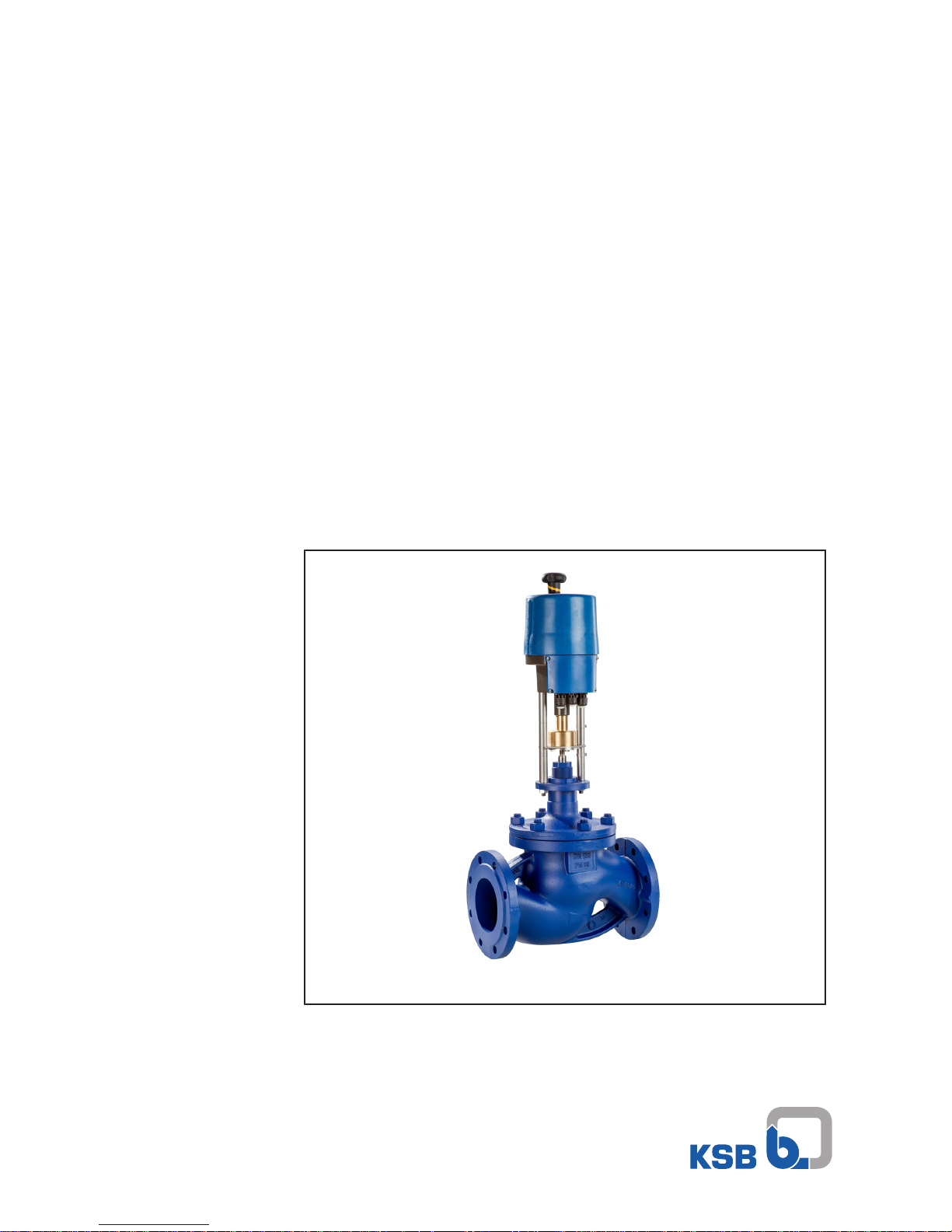
Control Valve Actuators
EA-C
For Type Series BOA-CVE H and BOA-H Mat E
Installation/Operating Manual
Page 2

Legal information/Copyright
Installation/Operating Manual EA-C
Original operating manual
All rights reserved. The contents provided herein must neither be distributed, copied, reproduced,
edited or processed for any other purpose, nor otherwise transmitted, published or made available to a
third party without the manufacturer's express written consent.
Subject to technical modification without prior notice.
© KSB SE & Co. KGaA, Frankenthal 10/08/2018
Page 3

Contents
3 of 44
EA-C
Contents
1 General.................................................................................................................................................... 5
1.1 Principles ...........................................................................................................................................................5
1.2 Target group.....................................................................................................................................................5
1.3 Symbols .............................................................................................................................................................5
2 Safety...................................................................................................................................................... 6
2.1 Key to safety symbols/markings.......................................................................................................................6
2.2 General..............................................................................................................................................................6
2.3 Intended use .....................................................................................................................................................7
2.4 Personnel qualification and training...............................................................................................................7
2.5 Consequences and risks caused by non-compliance with this manual .........................................................7
2.6 Safety awareness ..............................................................................................................................................7
2.7 Safety information for the user/operator.......................................................................................................7
2.8 Safety information for maintenance, inspection and installation ................................................................8
2.9 Unauthorised modes of operation..................................................................................................................8
3 Transport/Temporary Storage/Disposal............................................................................................... 9
3.1 Checking the condition upon delivery............................................................................................................9
3.2 Transport...........................................................................................................................................................9
3.3 Storage/preservation........................................................................................................................................9
3.4 Disposal/recycling .............................................................................................................................................9
4 Description............................................................................................................................................ 10
4.1 General description ........................................................................................................................................10
4.2 Designation.....................................................................................................................................................10
4.3 Name plate......................................................................................................................................................10
4.4 Design details..................................................................................................................................................11
4.5 Installation types ............................................................................................................................................12
4.6 Noise characteristics .......................................................................................................................................12
4.7 Dimensions and weights ................................................................................................................................12
5 Reassembly........................................................................................................................................... 13
5.1 Safety regulations...........................................................................................................................................13
5.2 Checking prior to installation/assembly........................................................................................................13
5.3 Mounting the actuator ..................................................................................................................................14
5.4 Electrical connection ......................................................................................................................................16
5.5 Interfaces.........................................................................................................................................................19
5.6 Heating resistor (optional).............................................................................................................................21
5.7 Setting the limit switches...............................................................................................................................21
6 Commissioning/Start-up/Shutdown................................................................................................... 23
6.1 Prerequisites for commissioning/start-up......................................................................................................23
6.2 Commissioning/Start-up.................................................................................................................................23
6.3 Operating limits..............................................................................................................................................24
6.4 Shutdown........................................................................................................................................................24
6.5 Returning to service .......................................................................................................................................24
7 Servicing/Maintenance........................................................................................................................ 25
7.1 Safety regulations...........................................................................................................................................25
7.2 Removing the actuator ..................................................................................................................................26
7.3 Maintenance/inspection.................................................................................................................................26
7.4 Lubrication......................................................................................................................................................27
7.5 Cleaning ..........................................................................................................................................................27
7.6 Mounting the actuator ..................................................................................................................................27
7.7 Spare parts stock.............................................................................................................................................27
Page 4

Contents
4 of 44
EA-C
8 Trouble-shooting.................................................................................................................................. 28
9 Related Documents.............................................................................................................................. 30
9.1 General assembly drawing, handwheel on top (EA-C 20 to 140)................................................................30
9.2 General assembly drawing, side-mounted handwheel (EA-C 200 to 250)..................................................31
9.3 Wiring diagrams .............................................................................................................................................32
9.4 Technical data.................................................................................................................................................35
10 EU Declaration of Conformity............................................................................................................. 40
11 Declaration of Incorporation of Partly Completed Machinery ......................................................... 41
Index ..................................................................................................................................................... 42
Page 5
1 General
5 of 44
EA-C
1 General
1.1 Principles
This operating manual is valid for the type series and variants indicated on the front
cover.
The manual describes the proper and safe use of this equipment in all phases of
operation.
The name plate indicates the type series, the main operating data and the serial
number. The serial number uniquely describes the product and is used as
identification in all further business processes.
In the event of damage, immediately contact your nearest KSB Service centre to
maintain the right to claim under warranty.
1.2 Target group
This operating manual is aimed at the target group of trained and qualified specialist
technical personnel.
1.3 Symbols
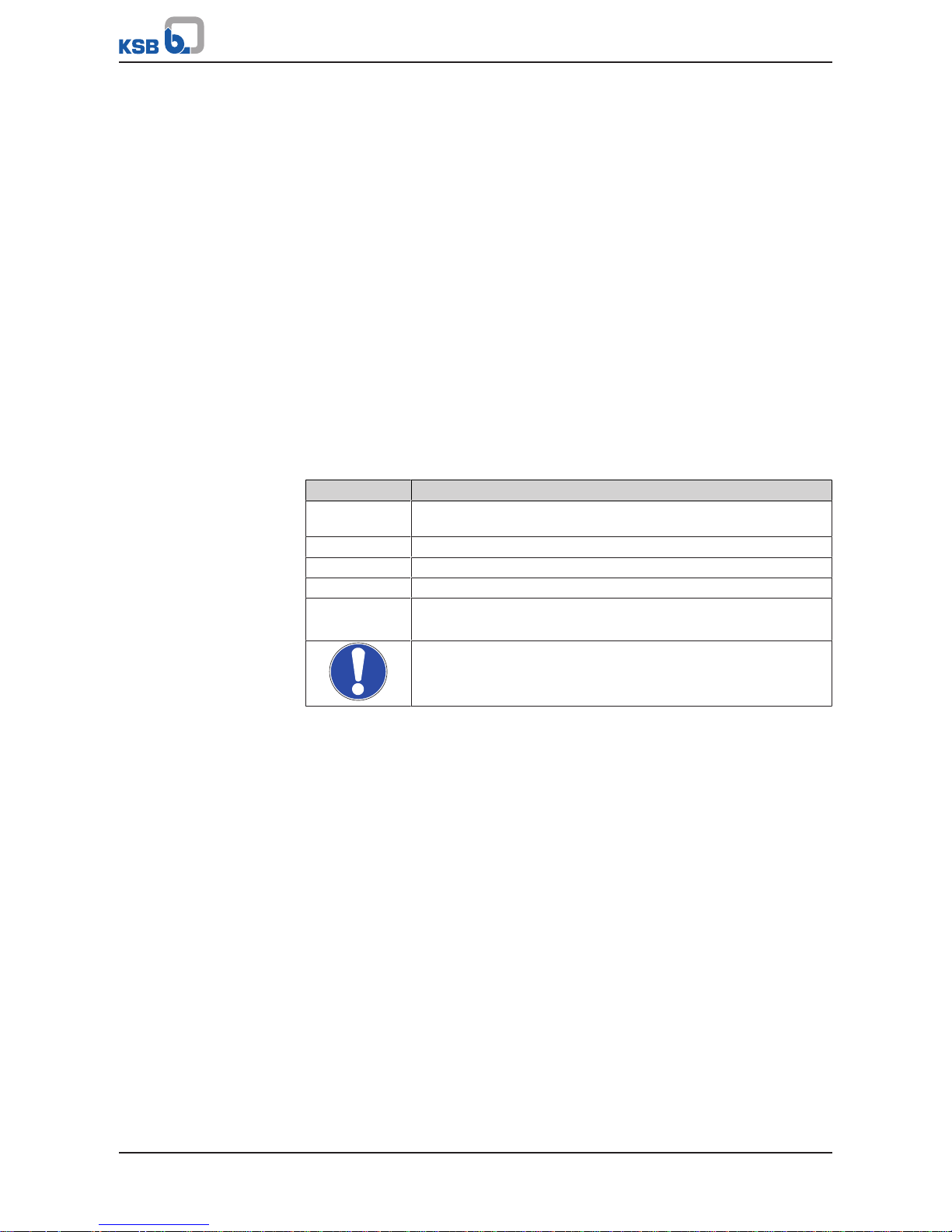
Table1: Symbols used in this manual
Symbol Description
✓ Conditions which need to be fulfilled before proceeding with the
step-by-step instructions
⊳ Safety instructions
⇨
Result of an action
⇨ Cross-references
1.
2.
Step-by-step instructions
Note
Recommendations and important information on how to handle
the product
Page 6
2 Safety
6 of 44
EA-C
2 Safety
!
DANGER
All the information contained in this section refers to hazardous situations.
In addition to the present general safety information the action-related safety
information given in the other sections must be observed.
2.1 Key to safety symbols/markings
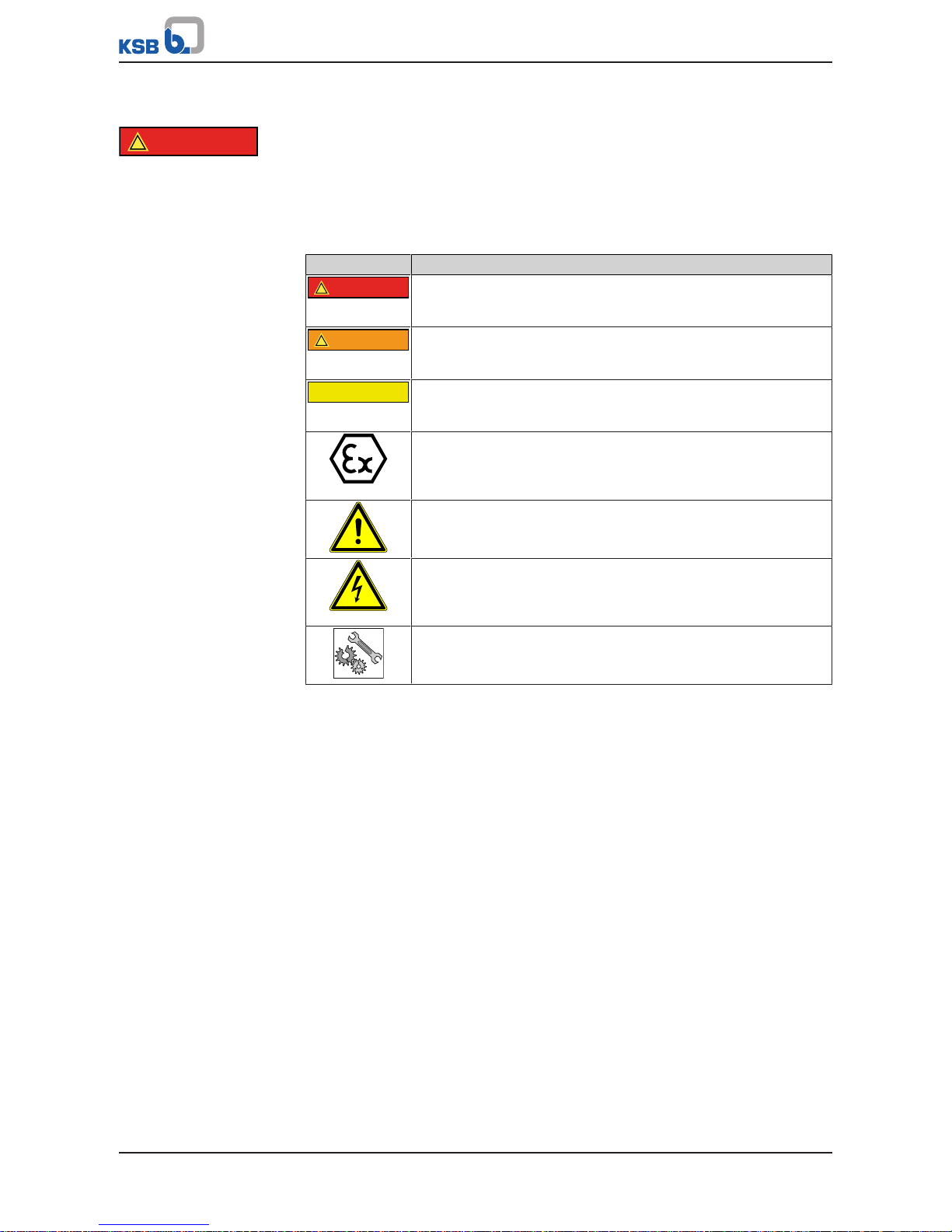
Table2: Definition of safety symbols/markings
Symbol Description
!
DANGER
DANGER
This signal word indicates a high-risk hazard which, if not avoided,
will result in death or serious injury.
!
WARNING
WARNING
This signal word indicates a medium-risk hazard which, if not
avoided, could result in death or serious injury.
CAUTION
CAUTION
This signal word indicates a hazard which, if not avoided, could
result in damage to the machine and its functions.
Explosion protection
This symbol identifies information about avoiding explosions in
potentially explosive atmospheres in accordance with EU Directive
2014/34/EU (ATEX).
General hazard
In conjunction with one of the signal words this symbol indicates a
hazard which will or could result in death or serious injury.
Electrical hazard
In conjunction with one of the signal words this symbol indicates a
hazard involving electrical voltage and identifies information about
protection against electrical voltage.
Machine damage
In conjunction with the signal word CAUTION this symbol indicates
a hazard for the machine and its functions.
2.2 General
This operating manual contains general installation, operating and maintenance
instructions that must be observed to ensure safe operation of the system and
prevent personal injury and damage to property.
The safety information in all sections of this manual must be complied with.
The operating manual must be read and understood by the responsible specialist
personnel/operators prior to installation and commissioning.
The contents of this operating manual must be available to the specialist personnel
at the site at all times.
Information attached directly to the product must always be complied with and kept
in a perfectly legible condition at all times. This applies to, for example:
▪ Markings for connections
▪ Name plate
The operator is responsible for ensuring compliance with all local regulations not
taken into account in this operating manual.
This electric motor has been designed and constructed in accordance with the
requirements of Directive 2014/35/EU (“Low-voltage Directive”). It is intended for use
in industrial plants.
If the motor is used in countries outside the European Community, adhere to the
regulations applicable to the relevant country. Also observe any local and industryspecific regulations governing installation and safety.
Page 7

2 Safety
7 of 44
EA-C
2.3 Intended use
▪ Only operate actuators which are in perfect technical condition.
▪ Do not operate partially assembled actuators.
▪ Generally observe the operating limits given.
▪ Consult the manufacturer about any use or mode of operation not described in
the data sheet or product literature.
Prevention of foreseeable misuse
▪ Never exceed the permissible application and operating limits specified in the
data sheet or product literature regarding pressure, temperature, etc.
▪ Observe all safety information and instructions in this manual.
2.4 Personnel qualification and training
All personnel involved must be fully qualified to transport, install, operate, maintain
and inspect the product this manual refers to. The responsibilities, competence and
supervision of all personnel involved in installation, operation, maintenance and
inspection must be clearly defined by the operator.
Deficits in knowledge must be rectified by means of training and instruction
provided by sufficiently trained specialist personnel. If required, the operator can
commission the manufacturer/supplier to train the personnel.
Training on the product must always be supervised by specialist technical personnel.
2.5 Consequences and risks caused by non-compliance with this manual
▪ Non-compliance with these operating instructions will lead to forfeiture of
warranty cover and of any and all rights to claims for damages.
▪ Non-compliance can, for example, have the following consequences:
– Hazards to persons due to electrical, thermal, mechanical and chemical
effects and explosions
– Failure of important product functions
– Failure of prescribed maintenance and servicing practices
– Hazard to the environment due to leakage of hazardous substances
2.6 Safety awareness
In addition to the safety information contained in this manual and the intended use,
the following safety regulations shall be complied with:
▪ Accident prevention, health regulations and safety regulations
▪ Explosion protection regulations
▪ Safety regulations for handling hazardous substances
▪ Applicable standards, directives and laws
2.7 Safety information for the user/operator
▪ Fit protective equipment (e.g. contact guards) supplied by the operator for hot,
cold or moving parts, and check that the equipment functions properly.
▪ Do not remove any protective equipment (e.g. contact guards) during operation.
▪ Provide the personnel with protective equipment and make sure it is used.
▪ Eliminate all electrical hazards. (In this respect refer to the applicable national
safety regulations and/or regulations issued by the local energy supply
companies.)
Page 8

2 Safety
8 of 44
EA-C
2.8 Safety information for maintenance, inspection and installation
▪ Modifications or alterations of the actuator are only permitted with the
manufacturer's prior consent.
▪ Use only original spare parts or parts/components authorised by the
manufacturer. The use of other parts/components can invalidate any liability of
the manufacturer for resulting damage.
▪ The operator ensures that maintenance, inspection and installation is performed
by authorised, qualified specialist personnel who are thoroughly familiar with
the manual.
▪ Any work on the product shall only be performed when it has been disconnected
from the power supply (de-energised).
▪ Carry out work on the product during standstill only.
▪ As soon as the work has been completed, re-install and re-activate any safety-
relevant devices and protective devices. Before returning the product to service,
observe all instructions on commissioning. (ðSection6.2,Page23)
2.9 Unauthorised modes of operation
Never operate the product outside the limits stated in the data sheet and in this
manual.
The warranty relating to the operating reliability and safety of the product supplied
is only valid if the product is used in accordance with its intended use.
Page 9
3 Transport/Temporary Storage/Disposal
9 of 44
EA-C
3 Transport/Temporary Storage/Disposal
3.1 Checking the condition upon delivery
1. On transfer of goods, check each packaging unit for damage.
2. In the event of in-transit damage, assess the exact damage, document it and
notify KSB or the supplying dealer and the insurer about the damage in writing
immediately.
3.2 Transport
CAUTION
Impacts against the coupling when placing in a horizontal or vertical position
Damage to the coupling!
▷ Place a suitable support underneath the coupling half when placing it in a
horizontal or vertical position.
Transport the actuator carefully and in its original packaging. Avoid damaging the
coating.
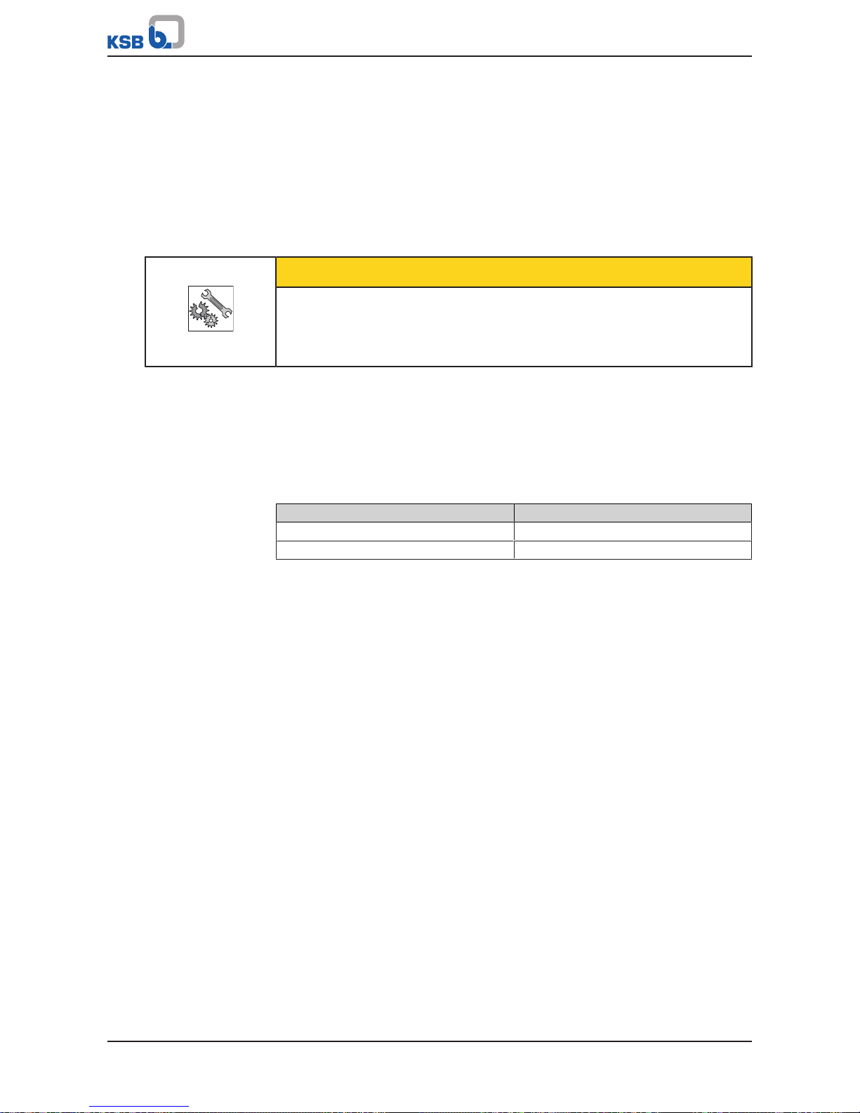
3.3 Storage/preservation
If commissioning is to take place some time after delivery, we recommend that the
following measures be taken:
Table3: Ambient conditions for storage
Ambient condition Value
Storage temperature -20°C to +80°C
Humidity 5 % to 95 % rH
▪ Well-ventilated
▪ Dry
▪ Dust-free
▪ Shock-free
▪ Vibration-free
3.4 Disposal/recycling
Due to some components, the product is classified as special waste.
1. Dismantle the product.
2. Separate and sort the materials, e.g. by:
- Metals
- Plastics
- Electronic waste
- Greases and other lubricants
3. Dispose of materials in accordance with local regulations or in another
controlled manner. PCBs, power electronics, capacitors and electronic
components are all hazardous waste.
Page 10
4 Description
10 of 44
EA-C
4 Description
4.1 General description
▪ Actuator for the automation of a control valve
Actuator with continuous-action or 3-point actuation in 24VAC/DC, 230VAC and
400VAC 3~. Actuator for valve type series BOA-CVE H and BOA-H Mat E.
Versions
Continuous-action actuators in 24VAC/DC, 230VAC and 400VAC 3~ versions and a
24VAC 3-point version
Variable speed actuator
control
▪ 24VDC motor, controlled by pulse-width modulation (PWM)
▪ Absolute-coded feedback via precision potentiometer
▪ Positioning function
▪ Active feedback function
▪ Automatic commissioning
▪ Comprehensive diagnosis options
Parameterisation by
software
▪ Actuator functions can be adapted to a wide variety of process conditions by
means of current and voltage monitoring.
▪ Setting of valve-specific details
▪ Setting of actuating force and actuating moment
▪ Setting of stroke and actuating speed
▪ Configuration of messages
▪ Freely programmable characteristic curve corrections
3-point actuators in 230VAC and 400V AC 3~ versions
▪ The actuator can be set by limit switches in both opening and closing direction
▪ Torque transmission by disc spring stack in closing direction.
▪ 2 limit switches for visualising the limit positions included as standard
4.2 Designation
Example: EA-C 250
Table4: Designation key
Code Description
EA-C Product name
250 Actuator size and maximum actuating force of 25kN
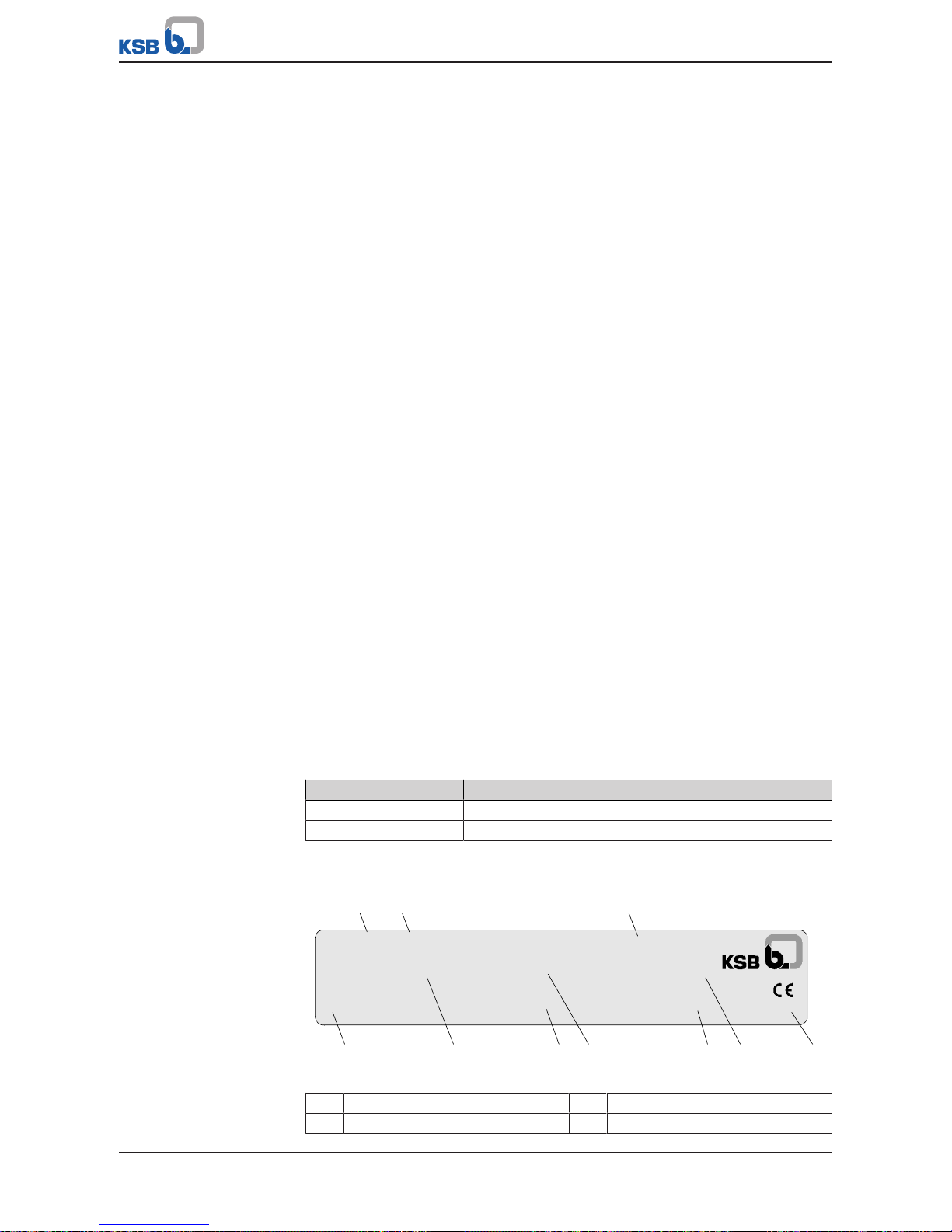
4.3 Name plate
EA-C Antrieb
Auftrag / Pos.:
order No. / pos.:
2120000000 / 0000
Stellkraft:
act. force:
....... N
Istwert:
feedback:
.......
Sollwert:
set value:
.......
Antrieb:
actuator:
EA- C ....
IP..
Betriebsspannung:
power supply:
....... V
Antriebsnummer:
actuator no.:
............
1 2 3
4 5 6 7 8 9 10
Fig.1: Actuator name plate (example)
1 Order number 2 Order item number
3 Product name 4 Supply voltage
Page 11
4 Description
11 of 44
EA-C
5 Actuating force 6 Actual value
7 Setpoint 8 Actuator number
9 Actuator size 10 Enclosure
4.4 Design details
Operating modes
▪ IEC 34-1, 8: S2 for short-time duty
▪ IEC 34-1, 8: S4 for control duty
Actuating force
2kN to 25kN
Actuating speed
1)
▪ Continuous-action actuation: 0.2mm/s to 1.3mm/s
▪ 3-point actuation: 0.45mm/s to 1.4mm/s
Enclosure
▪ EA-C 20: IP65 to EN 60529
▪ EA-C 40: IP65 to EN 60529
▪ EA-C 80: IP65 to EN 60529
▪ EA-C 140: IP67 to EN 60529
▪ EA-C 200: IP65 to EN 60529
▪ EA-C 250: IP65 to EN 60529
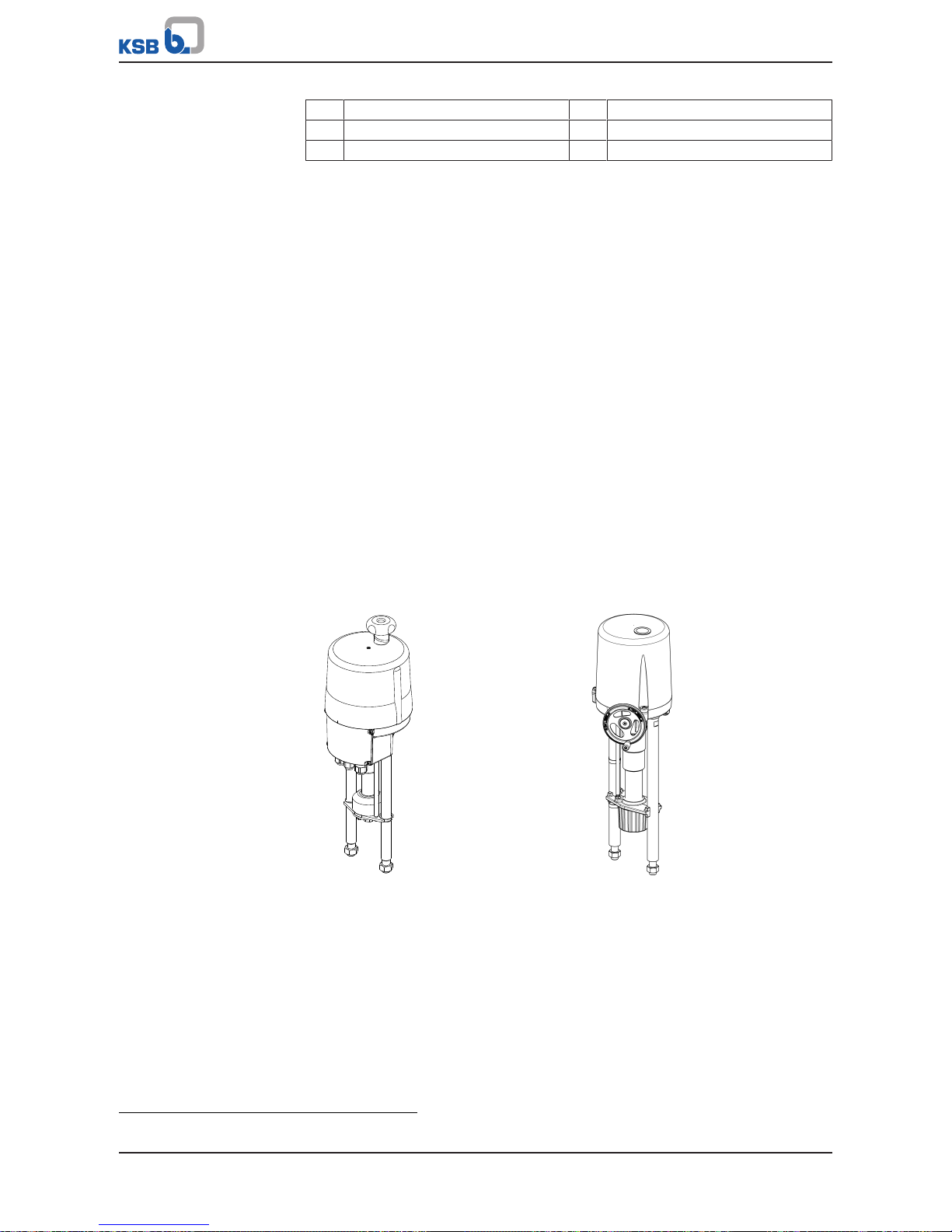
Design
Handwheel on top (EA-C 20 to 140) Side-mounted handwheel (EA-C 200 to
250)
▪ Configurable, microprocessor-controlled actuators
– Supply voltage: 24VAC/DC, 230VAC, 400VAC 3~
– Position setpoint: 4-20 mA, 0/2-10V
– Actual-position feedback: 4-20 mA, 0/2-10V
– Limit switching is torque-dependent in closing direction and stroke-
dependent in opening direction.
▪ 3-point actuators
– Supply voltage: 230VAC, 400VAC 3~
1) Depending on the actuator type
Page 12

4 Description
12 of 44
EA-C
– Actual-position feedback: 2 limit switches
– Stopping via limit switches in closing and opening direction
▪ Actuating time between 23 and 150seconds, depending on the stroke
▪ Operating data stored in permanent memory
▪ After a power failure, operation is resumed in accordance with the operating
data.
Variants
▪ Actuator configured to match the order specification
▪ Integrated process controller
▪ Power back-up unit
▪ Heating of the motor space
▪ Local control unit
▪ Additional limit switch for continuous-action actuators
▪ Optional potentiometer for 3-point actuators
▪ PSPT2) for 3-point actuators
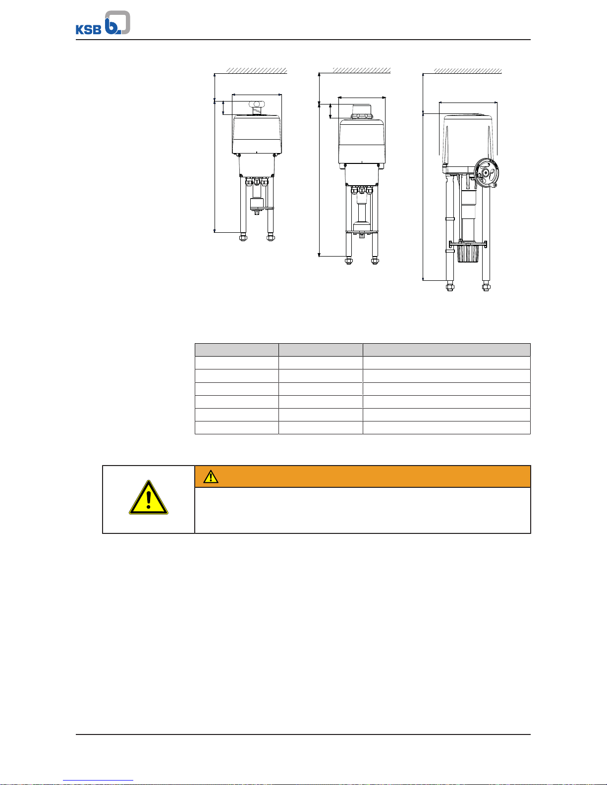
4.5 Installation types
The installation position as shown in the drawing below must be adhered to.
Fig.2: Types of installation for EA-C actuator
4.6 Noise characteristics
The sound pressure level depends on the local conditions and the duty point. It is
≤70dB(A).
4.7 Dimensions and weights
For dimensions and weights please refer to the type series booklet.
2) Optional potentiometer with printed circuit board for converting the resistance into a 4-20 mA output current signal
(additional 24V DC power supply required)
Page 13
5 Reassembly
13 of 44
EA-C
5 Reassembly
5.1 Safety regulations
DANGER
Electrical connection work by unqualified personnel
Risk of fatal injury due to electric shock!
▷ Always have any work on the connection to the power supply performed by a
trained electrician.
WARNING
Improper handling of an electric actuator
Crushing of fingers!
Damage to the actuator or the valve!
▷ When mounting the actuator onto the valve make sure that the power supply
has not yet been connected or that the actuator is secured against
unintentional start-up.
▷ Ensure that any objects and parts of the body are removed from the actuator
coupling area prior to starting the actuator.
WARNING
Incorrect connection to the mains
Damage to the mains network, short circuit!
▷ Observe the technical specifications of the local energy supply companies.
▷ Inspect the power cable for visible damage.
▷ Never connect damaged power cables.
CAUTION
Painting of pipes
Impairment of the valve's function and loss of information!
▷ Protect stem and plastic components prior to applying paint.
▷ Protect printed name plates prior to applying paint.
5.2 Checking prior to installation/assembly
▪ Check the actuator's compatibility with the valve.
▪ Check whether the valve has been prepared for assembly to the actuator.
▪ Check whether the actuator cover needs to be dismantled.
– The actuator cover on EA-C actuator sizes 200 to 250 and EA-C 3-point
actuators needs to be dismantled. (ðSection5.4,Page16)
▪ Make sure that there is a minimum wall clearance for removing the actuator
cover.
Page 14
5 Reassembly
14 of 44
EA-C
A
X
X
X
Ø 180
Ø 180
Ø 250
A
A
50
52
EA-C 20, 40, 80 EA-C 140 EA-C 200, 250
Fig.3: Actuator with minimum wall clearance X
Table5: Dimensions [mm]
Actuator A Minimum wall clearance X
EA-C 20 478,2 100
EA-C 40 481 100
EA-C 80 510,3 100
EA-C 140 579 120
EA-C200 720 230
EA-C250 720 230
5.3 Mounting the actuator
WARNING
Electrical operation of the actuator
Crushing of hands!
▷ Use only the handwheel to operate the actuator during assembly/dismantling.
Page 15

5 Reassembly
15 of 44
EA-C
a
b
c
d
e
f
g
h
i
EA-C 20 - 140 EA-C 200 - 250
Fig.4: Mounting of EA-C actuator sizes 20 to 250
a Coupling
b Coupling nut
c Tensioning screw
d Screwed insert
e Pillar
f Stem
g Locknut
h Top flange
3)
i Pillar nut
ü The handwheel4) has been used to move the coupling (a) into its top starting
position.
1. Check that the coupling nut (b) can be turned by hand. If it cannot be rotated,
loosen either the 4 tensioning screws (c) or the screwed insert (d), depending on
the design.
CAUTION
Tensioning screws or screwed insert too loose
Internal coupling parts may fall out!
▷ Reinsert the internal coupling parts in accordance with the disc spring
arrangement diagram.
2. Insert the actuator pillars (e) in the drilled holes provided in the top flange3) (h).
3. Screw the pillar nuts (i) onto the threads of the pillars (e). Make sure to keep a
distance of approx. 5mm from the top flange3) (h).
4. Turn the handwheel to extend the coupling (a) until the coupling nut (b) rests
on the stem (f).
5. Keep on turning until the gap between the pillar shoulders and the top flange
3)
(h) is approx. 5mm.
3) Control valve flange for mounting the actuator
4) To turn the handwheel of EA-C 200 to 250 actuators, press the coupling button on the top of the actuator cover until it
latches in the down position.
Page 16

5 Reassembly
16 of 44
EA-C
6. Use an open-ended wrench to screw the coupling nut (b) onto the stem (f) until
the pillar shoulders rest on the top flange3) (h).
7. Continue until the stem thread is screwed into the coupling nut (b).
ð Thread engagement depth for M10: 12mm
ð Thread engagement depth for M14: 16mm
8. Secure the coupling nut (b) with the locknut (g).
9. For EA-C 20 to 140 actuators, tighten the tensioning screws (c) crosswise to a
torque of 8Nm. On EA-C 200 to 250 actuators, tighten the screwed insert (d)
hand-tight as far as it will go using a pin-type face wrench.
10. Operate the coupling (a) with the handwheel until the pillar shoulders rest on
the top flange3) (h).
1
2
Fig.5: Illustration of correct screwed condition
1 Pillar shoulder 2 Top flange
3)
11. Tighten the pillar nuts (i) to a torque of 56Nm.
EA-C 20
EA-C 40
EA-C 140
EA-C 200 - 250
EA-C 80
Fig.6: Disc spring arrangement diagrams of EA-C 20 to 250 actuators
5.4 Electrical connection
DANGER
Electrical connection work by unqualified personnel
Danger of death from electric shock!
▷ Always have the electrical connections installed by a trained and qualified
electrician.
▷ Observe regulations IEC60364.
DANGER
Work performed on an energised terminal box
Danger of death from electric shock!
▷ Switch off the power supply at least 5minutes prior to commencing work and
ensure that it cannot be switched on again unintentionally.
Page 17

5 Reassembly
17 of 44
EA-C
WARNING
Sudden start-up of the continuous-action actuator with power back-up unit after
disconnection from the mains.
Crushing of hands!
▷ Disconnect the equipment from the power supply.
▷ Secure against unauthorised start-up.
CAUTION
Pressing down the actuator cover with force
Damage to components!
▷ Turn the actuator cover gently to and fro until you can feel it lock in position.
NOTE
The terminal box has terminals for connecting solid and flexible electrical cables
with cross-sections from 0.14mm2 to 2.5mm2 as well as a PE terminal on the
housing.
Depending on the actuator, the terminal box is located behind the terminal box
cover or under the actuator cover.
Terminal box behind the terminal box cover (on continuous-action actuators and
24V 3-point actuators)
Fig.7: Undo the screws.
1. Undo and store the terminal box screws.
2. Remove the terminal box cover.
3. Unscrew the cable gland.
4. Choose the supply voltage and control signals in accordance with the data on
the name plate.
5. Connect the cables for power supply and control to the terminals as shown in
the wiring diagram. (ðSection9.3,Page32)
ð Use separate power cables for this purpose.
Fig.8: Power cable and control cable
6. Mechanically secure the power cable and the control cable before the terminals
against loosening.
7. Fasten the cable gland.
8. Fasten the terminal box cover with the screws.
ð Only tighten the screws until resistance can be felt.
Page 18

5 Reassembly
18 of 44
EA-C
Terminal box under the actuator cover (handwheel on top - on 230V and 400V 3point actuators)
Fig.9: Loosen the protective
cap of EA-C 140
Fig.10: Undo the fastening
screw of EA-C 20
1. For EA-C 140 actuators, unscrew the protective cap.
2. Loosen and store the fastening screw of the handwheel.
3. Remove the handwheel.
4. For EA-C 140 actuators, loosen and store the hexagon socket head cap screws of
the actuator cover.
5. Use both hands to gently lift off the actuator cover.
6. Unscrew the cable gland.
7. Choose the supply voltage and control signals in accordance with the data on
the name plate.
8. Connect the cables for power supply and control to the terminals as shown in
the wiring diagram. (ðSection9.3,Page32)
ð Use separate power cables for this purpose.
Fig.11: Power cable and control cable
9. Mechanically secure the power cable and the control cable before the terminals
against loosening.
10. Tighten the cable gland up to one full turn.
11. A thin coat of grease may be applied to the joint ring to facilitate fitting of the
actuator cover.
12. Properly place the joint ring in the groove of the housing.
Fig.12: Markings on
actuator cover / housing
13. Slip the actuator cover over the handwheel shaft.
14. Observe the marking.
15. Do not press down the actuator cover by force. Turn the actuator cover gently
to and fro until you can feel it lock in position.
16. Slide the actuator cover over the joint ring as far as it will go. When properly
seated, the actuator cover cannot be turned any more, and its lower edge is
flush with the housing edge.
17. Mount the handwheel on the handwheel shaft until it has seated. Secure the
handwheel with the fastening screw onto the flattened area of the shaft.
18. Fasten the actuator cover with the screws.
19. For EA-C 140 actuators, tighten the protective cap.
20. Fasten the cable gland.
Terminal box under the actuator cover (side-mounted handwheel, on EA-C 200 and
250 actuators)
Fig.13: Open the actuator
cover.
1. Undo the hexagon socket head cap screws from the actuator cover and store
them.
2. Use both hands to gently lift off the actuator cover.
3. Unscrew the cable gland.
4. Choose the supply voltage and control signals in accordance with the data on
the name plate.
5. Connect the cables for power supply and control to the terminals as shown in
the wiring diagram. (ðSection9.3,Page32)
ð Use separate power cables for this purpose.
Page 19

5 Reassembly
19 of 44
EA-C
Fig.14: Power cable and control cable
6. Mechanically secure the power cable and the control cable before the terminals
against loosening.
Fig.15: Close the actuator
cover.
7. Fasten the cable gland.
8. A thin coat of grease may be applied to the joint ring to facilitate fitting of the
actuator cover.
9. Properly place the joint ring in the groove of the housing.
10. Observe the marking.
11. Do not press down the actuator cover by force.
12. Slide the actuator cover over the joint ring as far as it will go. When properly
seated, the actuator cover cannot be turned any more, and its lower edge is
flush with the housing edge.
13. Fit the actuator cover and fasten it with the hexagon socket head cap screws.
14. Fasten the cable gland.
5.5 Interfaces
Communication
interface
A
Fig.16: Communication interface
The communication interface A is factory-set. A parameterisation kit (ident. No.:
46001269) for actuator communication and parameter setting can be ordered from
KSB. The PC is connected to the actuator via a USB interface and an RJ45 socket using
the communication cable supplied. All actuator parameters can be set with the
software (included in the parameterisation kit). The operating manual is also
included in the scope of supply.
Inputs
1
2
3
Fig.17: Galvanically isolated setpoint input
The parameterisable setpoint for closed-loop control is supplied to terminals 1 to 3
via 4-20mA or 0/2-10V signals.
Page 20

5 Reassembly
20 of 44
EA-C
15
16
17
Fig.18: Actual process value for process controller (optional)
Terminals 15 to 17 serve to connect the parameterisable actual process value via
4-20mA or 0/2-10V signals supplied by the process sensor, if the optional process
controller in the actuator is used.
NOTE
The binary inputs described below take priority over the setpoint supplied: If the
actuator parameters are set for closed-loop control, the actuator will not follow the
setpoint supplied as long as binary signals are received. Only after the signal has
been removed will the actuator return to the position stipulated by the setpoint.
9 10 11
Fig.19: Galvanically isolated binary inputs
The binary Open/Close signals are connected to terminals 9 to 11. These inputs are
rated for 24VAC/DC as standard. (ðSection9.3.3,Page34) The actuator is
operated in open-loop control mode in this configuration.
Outputs
4
5
6
Fig.20: Continuous actual-position feedback
Terminals 4 to 6 can be used for transmitting the parameterisable actual-position
value as a 4-20mA or 0/2-10V signal.
14
17
Fig.21: Power supply for process sensor (optional)
Page 21

5 Reassembly
21 of 44
EA-C
The output (terminals 14 and 17) supplies 21-40VDC unregulated voltage, 100mA
max.. If a feedback value transmitter is used to supply a setpoint signal for the
optional process controller, a fixed-voltage regulator must be used for 24VDC
voltage supplies. A fixed-voltage regulator is also required when using BOATRONIC
MS-420. For voltage tolerances please refer to the relevant product literature.
5.6 Heating resistor (optional)
On option, a heating resistor can be installed to heat the actuator's terminal
compartment. Condensation inside the actuator if used outdoors, in environments
with highly fluctuating ambient temperatures or high atmospheric humidity will thus
be prevented. The heating resistor inside the actuator is powered by the actuator's
power supply, i.e. separate mains connection is not required.
ü The power supply has been disconnected.
ü The actuator has been secured against unauthorised start-up.
ü The actuator has been moved into the set limit position.
ü The operating manual for the heating resistor included in the scope of supply is
on hand.
1. Open the actuator cover. (ðSection5.4,Page16)
2. For all other steps, see the operating manual supplied.
3. The internal cable must be routed in such a way that it cannot come into
contact with the actuator cover seal and/or moving components.
5.7 Setting the limit switches
The standard limit switches (1) and (2) of the 3-point actuator serve to stop the motor
when the limit positions have been reached. The additional limit switches (3) and (4)
are designed as volt-free changeover contacts for open/closed position feedback.
3
1
2
4
5
6
Fig.22: Setting the switching cams
1 Limit switch for CLOSED position 4 Switching cam for OPEN signal
2 Limit switch for OPEN position 5 Locking screw
3 Switching cam for CLOSED signal 6 Gear screw
Page 22

5 Reassembly
22 of 44
EA-C
Fitting of optional limit switches for continuous actuation
ü The power supply has been disconnected.
ü The actuator has been secured against unauthorised start-up.
ü The coupling has been fully extended using the handwheel.
ü The operating manual for the limit switches included in the scope of supply is on
hand.
1. Open the actuator cover. (ðSection5.4,Page16)
2. For all other steps, see the operating manual supplied.
NOTE
For straight-way valves, first set the CLOSED position force-dependent / stroke
dependent, then set the OPEN position stroke-dependent.
1. Use the handwheel to move the actuator into the limit position until the valve
disc touches the valve seat.
ð The position is reached when the valve stem starts to move axially against
the disc spring force in the stem nut.
2. Continue to operate the actuator until the disc springs are slightly precompressed (approx. 1.5mm).
3. Loosen the locking screw of the corresponding switching cam.
4. Turn the gear screw to move the switching cam towards the limit switch until
you hear the limit switch click.
5. Tighten the locking screw.
6. Check the setting by repeating the closing action electrically.
ð If the setting for the position is too low, the slip coupling will start making a
rattling noise. Re-adjust the cam as required.
7. On the basis of the lower limit position, read the required stroke on the scale to
set the OPEN position. Set the limit switch to this position.
8. Set the 2 volt-free changeover contacts so that they switch slightly before the
standard switches.
Page 23

6 Commissioning/Start-up/Shutdown
23 of 44
EA-C
6 Commissioning/Start-up/Shutdown
6.1 Prerequisites for commissioning/start-up
NOTE
Do not operate the actuator electrically before it has been mounted onto a valve.
Before commissioning/starting up the drive, make sure that the following conditions
are met:
▪ Check that the actuator has been properly installed and aligned
(ðSection4.5,Page12) .
▪ Make sure that the operating conditions correspond to the data specified and
those provided on the name plate.
▪ All fastening bolts, connecting elements, and electrical connections have been
properly tightened to the specified tightening torques.
▪ Implement all measures preventing accidental contact with moving and live
parts.
6.2 Commissioning/Start-up
6.2.1 Automatic commissioning of continuous-action and 24V AC/DC 3-point
actuators
The actuator is delivered in "initialised" mode and the green LED is lit. In this mode
the actuator responds to the setpoint supplied or to other operating commands.
If the actuator has been replaced, automatic commissioning must be performed.
Power supply must not be interrupted during commissioning.
If the actuator stroke is blocked during commissioning before the actuator has
reached a set stroke-dependent limit position, the value reached will be saved.
If no torque limit is found during commissioning, or the stroke determined is below
the permissible minimum stroke of 5mm, commissioning is aborted. The actuator
returns to the "non-initialised" state, which is indicated by the green LED flashing
slowly. This will also happen if the actuator has not been initialised correctly.
1
2
3
Fig.23: Commissioning button and LEDs
1 Commissioning button 2 Green LED
3 Red LED
ü Check whether the terminal box cover or the actuator cover needs to be
dismantled, see the selection table. (ðSection5.2,Page13)
1. Dismantle the terminal box cover or the actuator cover, depending on the
design. (ðSection5.4,Page16)
2. Press and hold the commissioning button (1) inside the terminal box for 3
seconds.
3. The initialisation process starts, the green LED (2) flashes and the actuator
completes a full cycle between the set limit positions.
Page 24

6 Commissioning/Start-up/Shutdown
24 of 44
EA-C
4. The green LED (2) lights up continuously.
ð The actuator has now been commissioned and is ready for operation.
5. Close the actuator cover or the terminal box cover, depending on the design.
(ðSection5.4,Page16)
6.2.2 Mechanical commissioning of 3-point actuators
ü Check whether the terminal box cover or the actuator cover needs to be
dismantled, see the selection table. (ðSection5.2,Page13)
1. Dismantle the terminal box cover or the actuator cover, depending on the
design. (ðSection5.4,Page16)
2. Use the handwheel to move the actuator to the middle of the valve travel.
3. Operate the actuator in both directions using the actuating signals until the
respective limit switches stop the actuator.
4. If limit switching is not correct, re-adjust the limit switches.
(ðSection5.7,Page21)
5. The green LED (2) is lit.
6. Close the actuator cover or the terminal box cover, depending on the design.
(ðSection5.4,Page16)
6.3 Operating limits
6.3.1 Ambient temperature
Observe the following parameters and values during operation:
Table6: Permissible ambient temperatures
Ambient condition Value
Ambient temperature -20°C to +60°C
Humidity 5 % to 95 % rH
6.4 Shutdown
1. Disconnect the equipment from the power supply.
ð If a power back-up unit is fitted, the stem moves into the set limit position.
2. Secure against unauthorised start-up.
ð If a power back-up unit is fitted, allow the capacitors to fully discharge
before further work is done. The discharge time is 3hours.
6.5 Returning to service
After maintenance work has been carried out on the actuator and/or valve during
which the stem coupling and disc spring stack were dismantled, the following points
must be observed after proper reassembly.
▪ An initialisation run must always be performed for continuous-action actuators.
(ðSection6.2.1,Page23)
▪ The limit switches of 3-point actuators must be checked. (ðSection5.7,Page21)
Page 25

7 Servicing/Maintenance
25 of 44
EA-C
7 Servicing/Maintenance
7.1 Safety regulations
The operator ensures that maintenance, inspection and installation is performed by
authorised, qualified specialist personnel who are thoroughly familiar with the
manual.
WARNING
Unintentional starting of the drive or driven machine
Risk of injury by moving components and shock currents!
▷ Always make sure the electrical connections are disconnected before carrying
out work on the drive or driven machine. In addition to the main circuits,
ensure that supplementary and auxiliary circuits are also disconnected.
▷ Mind the capacitor discharge time. After switching off the frequency inverter,
wait 10 minutes until dangerous voltages have discharged.
▷ Ensure that the drive cannot be started unintentionally.
WARNING
Insufficient stability
Risk of crushing hands and feet!
▷ Secure the motor against tilting or tipping over during assembly/dismantling.
A regular maintenance schedule will help avoid expensive repairs and contribute to
trouble-free, reliable operation of the drive with a minimum of maintenance
expenditure and work.
NOTE
All maintenance work, service work and installation work can be carried out by KSB
Service or authorised workshops. For contact details please refer to the enclosed
"Addresses" booklet or visit "www.ksb.com/contact" on the Internet.
Never use force when dismantling and reassembling the drive.
Page 26

7 Servicing/Maintenance
26 of 44
EA-C
7.2 Removing the actuator
a
b
c
d
e
f
g
h
i
EA-C 20 - 140 EA-C 200 - 250
Fig.24: Removing the actuators
a Coupling
b Coupling nut
c Tensioning screw
d Screwed insert
e Pillar
f Stem
g Locknut
h Top flange
5)
i Pillar nut
ü The power back-up unit of continuous-action actuators has been disconnected
separately.
1. Remove the actuator cover or the terminal box cover, depending on the
actuator. (ðSection5.4,Page16)
2. Disconnect the power cable and the control cable from the terminals.
3. Undo the pillar nuts (i).
4. For EA-C 20 to 140, loosen the tensioning screws (c). For EA-C 200 to 250, loosen
the screwed insert (d) with a pin-type face wrench.
5. Undo the locknut (g).
6. Tighten the coupling nut (b) with an open-ended wrench.
7. Use the handwheel to move the coupling (a) into its top starting position. If it
cannot be turned, loosen the 4 tensioning screws (c) or the screwed insert (d)
further, depending on the design.
8. Pull the actuator pillars (e) out of the drilled holes provided in the top flange
5)
(h) .
7.3 Maintenance/inspection
EA-C actuators are maintenance-free.
5) Control valve flange for mounting the actuator
Page 27

7 Servicing/Maintenance
27 of 44
EA-C
7.4 Lubrication
The gearing is lubricated for life and does not need to be relubricated.
The moving parts such as the stem and the coupling nut must be lubricated using
standardised lubricants to DIN 51825.
7.5 Cleaning
CAUTION
Improper cleaning of actuators
Damage to the actuator covers!
▷ Clean the actuators in dry condition only.
▷ Do not use solvents.
▷ Use a soft cloth.
▷ Do not use abrasive substances.
7.6 Mounting the actuator
After maintenance / inspection, the actuator must be mounted back onto the valve.
See (ðSection5.3,Page14) Connect the power cable and the control cable and
mechanically secure them before the terminals against loosening.
(ðSection5.4,Page16) For returning the actuator into service after maintenance
and mounting, see (ðSection6.5,Page24)
7.7 Spare parts stock
In the case of damage and malfunction, a full replacement is recommended.
Page 28

8 Trouble-shooting
28 of 44
EA-C
8 Trouble-shooting
WARNING
Improper work to remedy faults
Risk of injury!
▷ For any work performed to remedy faults, observe the relevant information
given in this operating manual and/or in the product literature provided by the
accessories manufacturer.
If problems occur that are not described in the following table, consultation with the
KSB customer service is required.
Faults are indicated by a green and a red LED inside the terminal box. For this
purpose, the terminal box cover or the actuator cover must be dismantled,
depending on the design. (ðSection5.4,Page16)
A The red LED lights up continuously.
B The red LED flashes rapidly.
C The red LED flashes slowly.
D Red LED not lit.
E The green LED lights up continuously.
F The green LED flashes rapidly.
G The green LED flashes slowly.
H Green LED not lit.
Table7: Trouble-shooting for statuses
A B C D E F G H Status Possible cause Remedy
- - - ✘ - - - ✘ Actuator does not respond;
both status LEDs are off.
No power supply Check mains connection.
Voltage supplied does not
match the supply voltage
indicated on the name plate.
Apply correct supply voltage.
- - - ✘ ✘ - - - Actuator does not cover the
full valve travel.
Initialisation has not been
performed correctly.
Repeat initialisation
procedure.
Insufficient stroke has been
set for stroke-dependent limit
position.
Check valve travel parameter
settings.
- - - ✘ ✘ - - - Actuator does not provide
correct valve shut-off.
Initialisation has not been
performed correctly.
Repeat initialisation
procedure.
Actuator's closing force /
closing torque is insufficient.
Verify actuator selection.
- - - ✘ ✘ - - - Actuator is in normal
operating mode but does not
respond to setpoint
modifications.
Actuator has been configured
as process controller.
Connect the process sensor.
- - - ✘ ✘ - - - Actuator position does not
match the setpoint supplied.
A non-linear characteristic has
been parameterised.
Check parameters of
characteristic.
Table8: Trouble-shooting for operating modes
A B C D E F G H Operating modes Possible cause Remedy
- - - ✘ ✘ - - - Normal operating mode - -
- - - ✘ - ✘ - - Actuator is in initialisation
mode.
- Initialisation mode is exited
automatically upon
completion.
- - - ✘ - - ✘ - Actuator has not been
initialised.
- Run automatic initialisation.
Page 29

8 Trouble-shooting
29 of 44
EA-C
Table9: Trouble-shooting for faults in the actuator's environment
A B C D E F G H Faults in the actuator's
environment
Possible cause Remedy
- - ✘ - ✘ - - - An excessive torque has been
measured when the actuator
is run to its limit positions.
Actuator has not been
initialised correctly for the
valve actuated.
Repeat initialisation
procedure.
Actuator stroke is blocked
mechanically.
Check valve and actuator for
smooth operation.
Incorrect actuator selection Verify actuator selection.
- - ✘ - - ✘ - - No or incorrect actual process
value signal
Maximum control range is
exceeded.
No or incorrect actual process
value signal
Apply correct actual process
value signal, check polarity of
actual process value signal.
Actual process value not
within set range
Ensure correct actual process
value.
No signal provided by process
sensor.
Check process sensor or power
supply.
- - ✘ - - - ✘ - Actuator moves to a pre-set
position.
A signal has been applied to
the fail-safe binary input.
Disconnect signal.
Mains power failure on
actuator options with
rechargeable battery pack
(Accupack)
Check power supply.
- - ✘ - - - - ✘ Setpoint signal not applied or
not within set range
Setpoint signal not applied Apply setpoint signal.
Wrong polarity of setpoint
signal
Check polarity of setpoint
signal.
Setpoint signal not within the
set range
Check setpoint range.
- ✘ - - ✘ - - - The limit position stored
during initialisation has not
been reached.
Dirt deposits on valve seat or
loosened valve seat
Check valve seat.
- ✘ - - - ✘ - - The limit position stored
during initialisation has been
exceeded.
Worn or defective valve seat Check valve seat.
- ✘ - - - - ✘ - Insufficient supply voltage in
the actuator
Incorrect mains connection Check mains connection.
Supply voltage fluctuations Check power supply. See data
sheet
Insufficient voltage supplied
by rechargeable battery (on
actuator options with
"accupack" rechargeable
battery pack)
Contact KSB Service.
Table10: Trouble-shooting for actuator faults
A B C D E F G H Actuator faults Possible cause Remedy
✘ - - - ✘ - - - Actuator has reached service
limit.
Wear and/or operating hours Contact KSB Service.
✘ - - - - ✘ - - Electronics fault/Invalid
parameter data
Power supply has been
interrupted during
initialisation.
Contact KSB Service.
Damaged electronic
component
✘ - - - - - ✘ - Critical or maximum actuator
temperature has been
reached.
Excessive frequency of starts Check control settings.
Ambient temperature too
high
Check ambient temperature
and reduce if possible. See
data sheet
✘ - - - - - - ✘ Mechanical actuator fault Damaged mechanical
component
Contact KSB Service.
Page 30

9 Related Documents
30 of 44
EA-C
9 Related Documents
9.1 General assembly drawing, handwheel on top (EA-C 20 to 140)
100
400
500
200
600
300
Fig.25: General assembly drawing, handwheel on top (EA-C 20 to 140)
Table11: List of components
Part No. Description Material
100 Handwheel Plastic
200 Actuator cover Plastic/Aluminium
300 Terminal box cover Plastic
400 Pillars Steel
500 Coupling Brass/PA
600 Double-ear clamps Steel
Page 31

9 Related Documents
31 of 44
EA-C
9.2 General assembly drawing, side-mounted handwheel (EA-C 200 to 250)
100
400
500
200
600
Fig.26: General assembly drawing, side-mounted handwheel (EA-C 200 to 250)
Table12: List of components
Part No. Description Material
100 Handwheel Plastic
200 Actuator cover Plastic / Aluminium
400 Pillars Steel
500 Coupling Brass / PA
600 Double-ear clamps Steel
Page 32

9 Related Documents
32 of 44
EA-C
9.3 Wiring diagrams
9.3.1 Wiring diagram, 230V AC 3-point (single-phase AC)
X10
X5
X9
X4
X6
X1
X11 X0
1
2
1
6
7
4
2
1
2
3
1
2
1
2
3
4
5
6
X2
X3
X7
PE
1
2
4
X5
PE
N
L2
L1
t
X1 Internal wiring
X2 Internal wiring
X3 Internal wiring
X4 Potentiometer 1
X5/1 Neutral
X5/2 Motor phase to open
X5/4 Motor phase to close
X5/6 Temperature switch as volt-free contact
X5/7 Temperature switch as volt-free contact
X6 Additional limit switches
X7 Not used
X8 Heating resistor
X9 Potentiometer 2
PE Earth connection on housing
Page 33

9 Related Documents
33 of 44
EA-C
9.3.2 Wiring diagram, 400VAC 3-point (three-phase AC)
X2
X7
4
3
2
2
1
1
X0
X10
S2
S1
X5 X4
X5_3
X5_2
X5_1
11
12
13
14
15
16
17
18
19
20
15
14
16
13
14
15
16
11
12
17
18
19
20
X5
t
PE
L3
L1
L2
N
1) 2)
1) Closed 2) Open
X5_1/17 Limit switch Closed
X5_1/18 Limit switch Closed
X5_1/19 Limit switch Open
X5_1/20 Limit switch Open
X5_2/13 Neutral conductor
X5_2/14 Phase L1 (400V AC)
X5_2/15 Phase L3 (400V AC)
X5_2/16 Phase L2 (400V AC)
X5_3 Temperature switch
X4 Potentiometer
Page 34

9 Related Documents
34 of 44
EA-C
9.3.3 Terminal configuration EA-C 20 to 250 with terminal box
Continuous-action actuation 24 V AC/DC, 230 V AC and 400 V AC 3~
1 2 3 4 5 6 7 8 9 10 11 12 13 14 15 16 17 18 19 20 21 22 23 RJ-45
TTL
Pushbutto
n
L1 L2 L3
↑ ↑ ↑ ↓ ↓ ↓ ↑↓ ↑↓ ↑ ↑ ↑ ↑ ↑ ↓ ↑ ↑ ↑ ↑↓ ↑↓ ↑↓ ↑↓ ↑ ↑ ↑ ↑ ↑
+0(2) - 10V
+0(4) - 20 mA
GND
+0(2) - 10 V
+0(4) - 20 mA
GND
Max. load
100mA at 24VDC
L OPENNL CLOSE
L (24V AC/DC)
N (24V AC/DC)
24V DC / 100mA
+0(2) - 10V
+0(4) - 20mA
GND
(Optional)
(Optional)
(Optional)
(Optional)
L (see name plate)
N (see name
plate)PE(Optional)
400 V AC 3~
400 V AC 3~
400 V AC 3~
PE
24 V AC/DC □
115V AC □
230V AC □
Ⓐ Ⓑ Ⓒ Ⓓ Ⓔ Ⓕ Ⓖ Ⓗ Ⓘ Ⓙ Ⓚ Ⓛ Ⓜ Ⓠ
Ⓝ Ⓞ Ⓟ
In continuous-action configuration, only the terminals in columns Ⓐ, Ⓑ and Ⓙ
are active.
3-point actuation 24V AC/DC
1 2 3 4 5 6 7 8 9 10 11 12 13 14 15 16 17 18 19 20 21 22 23 RJ-45
TTL
Pushbutto
n
↑ ↑ ↑ ↓ ↓ ↓ ↑↓ ↑↓ ↑ ↑ ↑ ↑ ↑ ↓ ↑ ↑ ↑ ↑↓ ↑↓ ↑↓ ↑↓ ↑ ↑
+0(2) - 10V
+0(4) - 20mA
GND
+0(2) - 10V
+0(4) - 20mA
GND
Max. load
100mA at 24VDC
L OPENNL CLOSE
L (24V AC/DC)
N (24V AC/DC)
24 V DC / 100 mA
+0(2) - 10V
+0(4) - 20mA
GND
(Optional)
(Optional)
(Optional)
(Optional)
L (see name plate)
N (see name plate)
PE
(Optional)
24 V AC/DC
□
115V AC □
230V AC □
Ⓐ Ⓑ Ⓒ Ⓓ Ⓔ Ⓕ Ⓖ Ⓗ Ⓘ Ⓙ Ⓚ Ⓛ Ⓜ
Ⓝ Ⓞ Ⓟ
In 3-point configuration, only the terminals in columns Ⓑ, Ⓓ and Ⓙ are active. Ⓓ
equals 24V AC/DC by default.
Table13: Key
Ⓐ Setpoint input Ⓙ Supply voltage: single-phase alternating current or
direct current
Ⓑ Active actual-position feedback Ⓚ Field bus connection (optional)
Ⓒ Volt-free fault message (optional) Ⓛ Communication with PC
Ⓓ Binary control (standard 24V AC/DC) Ⓜ Commissioning
Ⓔ Power failure signal
6)
Ⓝ Galvanically isolated 1 kV
Ⓕ Supply Ⓞ Process sensor (optional)
Ⓖ Actual value Ⓟ Limit switch, volt-free contact
Ⓗ Closed Ⓠ Power supply: three-phase current
Ⓘ Open
6) Optional connections for external power back-up unit.
Page 35

9 Related Documents
EA-C
35 of 44
9.4 Technical data
9.4.1 Technical data of EA-C 20 to 40 (continuous-action and 24VAC 3-point)
Table14: Technical data of EA-C 20 to 40 (continuous-action and 24VAC 3-point)
Characteristic EA-C 20 continuous-action EA-C 20 continuous-
action and 3-point
EA-C 40 continuous action EA-C 40 continuous-action
and 3-point
Actuating force [N] 2000 4000
Stroke [mm] 50
Handwheel turns [/10mm
stroke]
12
Actuating speed [mm/s] 0,45 - 0,9
Power supply [V] 230VAC 1~ 320 - 575VAC 3~ 24 V AC 1~ 230VAC 1~ 320 - 575VAC 3~ 24VAC 1~
Frequency [Hz] 50
Nominal current
7)
[A] 0,07 0,08
8)
0,7 (AC) / 0,4 (DC) 0,11 0,11
8)
1,1 (AC) / 0,7 (DC)
Maximum current
7)
[A] 0,1 0,11
8)
0,9 (AC) / 0,6 (DC) 0,14 0,14
8)
1,4 (AC) / 0,9 (DC)
Maximum power input9)[W] 13 22
8)
12 (AC) / 11 (DC) 19 28
8)
18 (AC) / 16 (DC)
Duty cycle
10)
IEC 60034-1,8 S2 30 minutes, S4 50% operating time - 1200 c/h
11)
Enclosure EN 60529 IP65
Allow. ambient
temperature
[°C] -20 to +60
Motor protection Thermal monitoring and overload protection
Weight (without
accessories)
[kg] 8
7) Values may be higher depending on accessories used.
8) At 400V 3-phase and 50Hz
9) At maximum actuating force; Values may be higher depending on accessories used.
10) At 25 °C ambient temperature
11) Cycles per hour
Page 36

9 Related Documents
36 of 44
EA-C
9.4.2 Technical data of EA-C 80 to 140 (continuous-action and 24VAC 3-point)
Table15: Technical data of EA-C 80 to 140 (continuous-action and 24VAC 3-point)
Characteristic EA-C 80 continuous-action EA-C 80 continuous-
action and 3-point
EA-C 140 continuous-action EA-C 140 continuous-action
and 3-point
Actuating force [N] 8000 14000
Stroke [mm] 50 65
Handwheel turns [/10mm
stroke]
12 40
Actuating speed [mm/s] 0,3 - 0,7 0,65 - 1,3
Power supply [V] 230VAC 1~ 320 - 575VAC 3~ 24 V AC 1~ 230VAC 1~ 320 - 575VAC 3~ 24VAC 1~
Frequency [Hz] 50
Nominal current
12)
[A] 0,22 0,18
13)
2,1 (AC) / 1,3 (DC) 0,48 0,35
13)
4,6 (AC) / 2,9 (DC)
Maximum current
12)
[A] 0,29 0,23
13)
2,7 (AC) / 1,7 (DC) 0,62 0,45
13)
6 (AC) / 3,7 (DC)
Maximum power input
14)
[W] 38 47
13)
35 (AC) / 32 (DC) 88 91
13)
82 (AC) / 69 (DC)
Duty cycle
15)
IEC 60034-1,8 S2 30 minutes, S4 50% operating time - 1200 c/h
16)
Enclosure EN 60529 IP65 IP67
Allow. ambient
temperature
[°C] -20 to +60
Motor protection Thermal monitoring and overload protection
Weight (without
accessories)
[kg] 10 12
12) Values may be higher depending on accessories used.
13) At 400V 3-phase and 50Hz
14) For maximum actuating force; Values may be higher depending on accessories used.
15) At 25 °C ambient temperature
16) Cycles per hour
Page 37

9 Related Documents
EA-C
37 of 44
9.4.3 Technical data of EA-C 20 to 140 (230VAC and 400 V 3~ 3-point)
Table16: Technical data of EA-C 20 to 140 (230VAC 3-point)
Characteristic EA-C 20 3-point EA-C 40 3-point EA-C 80 3-point EA-C 140 3-point
Actuating force [N] 2000 4000 8000 14000
Stroke [mm] 50 65
Handwheel turns [/10mm
stroke]
12 31 28
Actuating speed [mm/s] 0,5 1,4 0,5 1,4 0,65 0,45
Power supply [V] 230VAC 1~ 400VAC 3~ 230VAC 1~ 400VAC 3~ 230VAC 1~ 400VAC 3~ 230VAC 1~ 400VAC 3~
Frequency [Hz] 50 / 60
Nominal current
17)
[A] 0,5 0,13 0,08 0,21 0,23 0,13 0,23 0,13
Maximum current
17)
[A] 0,07 0,18 0,08 0,26 0,27 0,15 0,27 0,15
Maximum power input
18)
[W] 12 30 18 51 52 30 52 30
Duty cycle
19)
IEC 60034-1,8 S2 30 minutes, S4 50 % operating time - 1200 c/h
20)
Enclosure EN 60529 IP65 IP67
Allow. ambient temperature [°C] S2: -20 to +80, S4: -20 to +60
Motor protection Anti-jam
design
Temperature switch Anti-jam
design
Temperature switch Temperature switch
Weight (without accessories) [kg] 5,5 8 10
17) Values may be higher depending on accessories used.
18) For maximum actuating force; values may be higher depending on accessories used.
19) At 25 °C ambient temperature
20) Cycles per hour
Page 38

9 Related Documents
38 of 44
EA-C
9.4.4 Technical data of EA-C 200 to 250 (continuous-action and 24VAC 3-point)
Table17: Technical data of EA-C 200 to 250 (continuous-action and 24VAC 3-point)
Characteristic EA-C 200
continuous-action
and 3-point
EA-C 200
continuous-
action
EA-C 200
continuous-
action
EA-C 250
continuous-action
and 3-point
EA-C 250
continuous-
action
EA-C 250
continuous-
action
Actuating force [N] 20000 25000
Maximum positioning force
21)
[N] 10000 12500
Stroke [mm] 95
Handwheel turns [/10mm stroke] 50
Actuating speed [mm/s] 0,2 - 0,4
Power supply [V] 24VAC/DC 230VAC 320-575VAC 3~ 24VAC/DC 230VAC 320-575VAC 3~
Frequency [Hz] 50 (AC)
Nominal current
22)
[A] 4,2 (AC) / 2,6 (DC) 0,44 0,32
23)
4,6 (AC) / 2,9 (DC) 0,48 0,35
23)
Maximum current
22)
[A] 5,5 (AC) / 3,4 (DC) 0,57 0,42
23)
6 (AC) / 3,7 (DC) 0,62 0,42
23)
Maximum power input
24)
[W] 76 (AC) / 63 (DC) 81 85
23)
82 (AC) / 69 (DC) 88 91
23)
Duty cycle
25)
IEC 60034-1,8 S2 30minutes, S4 50% operating time
26)
Enclosure EN 60529 IP65
Allow. ambient temperature [°C] -20 to +60
Motor protection Electronic motor current monitoring incl. safety tripping
Weight (without accessories) [kg] 23
21) Permissible average actuating force over the entire stroke range
22) Values may be higher depending on accessories used.
23) At 400V 3-phase and 50Hz
24) For maximum actuating force; values may be higher depending on accessories used.
25) At 25 °C ambient temperature
26) Cycles per hour
Page 39

9 Related Documents
EA-C
39 of 44
9.4.5 Technical data of EA-C 200 to 250 (230 V and 400V AC 3-point)
Table18: Technical data of EA-C 200 to 250 (230 V and 400V AC 3-point)
Characteristic EA-C 200 3-point EA-C 200 3-point EA-C 250 3-point EA-C 250 3-point
Actuating force [N] 20000 25000
Maximum positioning force
27)
[N] 10000 12500
Stroke [mm] 95
Handwheel turns [/10mm stroke] 50
Actuating speed [mm/s] 1,0
Power supply [V] 230VAC 400VAC 3~ 230VAC 400VAC 3~
Frequency [Hz] 50
Nominal current
28)
[A] 0,58 0,4 0,62 0,5
Maximum current [A] 0,95 0,6 0,95 0,6
Maximum power input
29)
[W] 137 120 145 140
Duty cycle
30)
IEC 60034-1,8 S2 30minutes, S4 50% operating time
31)
Enclosure EN 60529 IP65
Allow. ambient temperature [°C] S2: -20 to +80, S4: -20 to +60
Motor protection Temperature switch
Feedback via 2 limit switches Provided
Weight (without accessories) [kg] 23
27) Permissible average actuating force over the entire stroke range
28) Values may be higher depending on accessories used.
29) For maximum actuating force; values may be higher depending on accessories used.
30) At 25 °C ambient temperature
31) Cycles per hour
Page 40

10 EU Declaration of Conformity
40 of 44
EA-C
10 EU Declaration of Conformity
Manufacturer: KSB SE & Co. KGaA
Johann-Klein-Straße 9
67227 Frankenthal (Germany)
The manufacturer herewith declares that the product:
KSBEA-C20, KSBEA-C40, KSBEA-C80, KSBEA-C140,
KSBEA-C200, KSBEA-C250
▪ is in conformity with the provisions of the following Directives as amended from time to time:
– 2011/65/EU: Restriction of the Use of Certain Hazardous Substances in Electrical and Electronic Equipment
(RoHS)
– 2014/30/EU: Electromagnetic Compatibility (EMC)
– 2014/35/EU: Electrical Equipment Designed for Use within Specific Voltage Limits (Low Voltage)
The manufacturer also declares that
▪ the following harmonised international standards have been applied:
– EN61000-6-2:2005
– EN61000-6-3:2007+A1:2011
– EN61010-1:2010
The EU Declaration of Conformity was issued in/on:
Frankenthal, 1 February 2018
Wolfgang Glaub
Integrated Management Germany
Dieter Hanewald
Product Management and Product Development II
Frankenthal
KSB SE & Co. KGaA
Johann-Klein-Str. 9
67227 Frankenthal
KSB SE & Co. KGaA
Johann-Klein-Straße 9
67227 Frankenthal
Page 41

11 Declaration of Incorporation of Partly Completed Machinery
41 of 44
EA-C
11 Declaration of Incorporation of Partly Completed Machinery
Manufacturer: KSB SE & Co. KGaA
Johann-Klein-Straße 9
67227 Frankenthal (Germany)
The manufacturer herewith declares for the partly completed machinery:
KSBEA-C20, KSBEA-C40, KSBEA-C80, KSBEA-C140,
KSBEA-C200, KSBEA-C250
▪ The following essential requirements of the Machinery Directive 2006/42/EC, Annex I, have been applied and
fulfilled:
– 1.1.2, 1.1.3, 1.1.5
– 1.2.1, 1.2.2, 1.2.6
– 1.3.2, 1.3.4, 1.3.7, 1.3.9
– 1.5.1, 1.5.4, 1.5.5, 1.5.6
– 1.7.1, 1.7.3, 1.7.4
▪ The relevant technical documentation has been compiled in accordance with Part B of Annex VII. This
documentation or parts hereof will be transmitted by post or electronically in response to a reasoned request
by the national authorities.
The partly completed machinery must not be put into service until the final machinery into which it is to be
incorporated has been declared in conformity with the provisions of the Machinery Directive 2006/42/EC, where
appropriate.
Person authorised to compile the technical file:
Dieter Hanewald
Product Management and Product Development II Frankenthal
KSB SE & Co. KGaA
Johann-Klein-Str. 9
67227 Frankenthal (Germany)
The Declaration of Incorporation was issued in/on:
Frankenthal, 1 February 2018
Dieter Hanewald
Product Management and Product Development II Frankenthal
KSB SE & Co. KGaA
Johann-Klein-Straße 9
67227 Frankenthal
Page 42

Index
42 of 44
EA-C
Index
C
Commissioning23
Commissioning/start-up23
D
Design11
Designation10
Disposal9
E
Event of damage5
F
Faults
Causes and remedies28
I
Installation/assembly13
K
Key to safety symbols/markings6
M
Misuse7
O
Operating modes11
P
Personnel7
Personnel qualification7
Preservation9
S
Safety6
Safety awareness7
Servicing/Maintenance25
Specialist personnel7
Storage9
T
Terminal configuration34
Training7
W
Warnings6
Warranty claims5
Page 43

Page 44

KSB SE & Co. KGaA
Johann-Klein-Straße 9 • 67227 Frankenthal (Germany)
Tel. +49 6233 86-0
www.ksb.com
7525.83/01-EN
 Loading...