

Page 1
Pressure Booster System
KSB Delta Solo
KSB Delta Solo SVP
Installation/Operating Manual
Page 2

Legal information/Copyright
Installation/Operating Manual KSB Delta Solo
Original operating manual
All rights reserved. The contents provided herein must neither be distributed, copied, reproduced,
edited or processed for any other purpose, nor otherwise transmitted, published or made available to a
third party without the manufacturer's express written consent.
Subject to technical modification without prior notice.
© KSB B.V., Alphen aan den Rijn, Nederland 03/09/2019
Page 3

Contents
Contents
Glossary .................................................................................................................................................. 5
1 General.................................................................................................................................................... 6
1.1 Principles ...........................................................................................................................................................6
1.2 Software changes .............................................................................................................................................6
1.3 Installation of partly completed machinery....................................................................................................6
1.4 Target group.....................................................................................................................................................6
1.5 Other applicable documents............................................................................................................................6
1.6 Symbols .............................................................................................................................................................6
1.7 Key to safety symbols/markings.......................................................................................................................7
2 Safety...................................................................................................................................................... 8
2.1 General..............................................................................................................................................................8
2.2 Intended use .....................................................................................................................................................8
2.2.1 Prevention of foreseeable misuse.......................................................................................................8
2.3 Personnel qualification and personnel training.............................................................................................9
2.4 Consequences and risks caused by non-compliance with this manual .........................................................9
2.5 Safety awareness ..............................................................................................................................................9
2.6 Safety information for the operator/user.......................................................................................................9
2.7 Safety information for maintenance, inspection and installation ................................................................9
2.8 Unauthorised modes of operation................................................................................................................10
2.9 Electromagnetic compatibility (EMC)............................................................................................................10
2.9.1 Interference emission requirements .................................................................................................10
2.9.2 Line harmonics requirements............................................................................................................11
2.9.3 Interference immunity requirements ...............................................................................................11
3 Transport/Temporary Storage/Disposal............................................................................................. 12
3.1 Checking the condition upon delivery..........................................................................................................12
3.2 Transport.........................................................................................................................................................12
3.3 Storage/preservation......................................................................................................................................12
3.4 Return to supplier ..........................................................................................................................................13
3.5 Disposal ...........................................................................................................................................................13
4 Description............................................................................................................................................ 15
4.1 General description ........................................................................................................................................15
4.2 Product information as per Regulation No. 1907/2006(REACH).................................................................15
4.3 Description......................................................................................................................................................15
4.4 Name plate......................................................................................................................................................15
4.5 Design details..................................................................................................................................................15
4.6 Configuration and function...........................................................................................................................16
4.7 Scope of supply...............................................................................................................................................17
4.8 Dimensions......................................................................................................................................................17
4.9 Terminal diagram ...........................................................................................................................................17
4.10 Potential equalisation ....................................................................................................................................18
5 Installation at Site................................................................................................................................ 19
5.1 Checks to be carried out prior to installation...............................................................................................19
5.2 Installing the pressure booster system..........................................................................................................19
5.3 Mounting the accumulator............................................................................................................................20
5.4 Connecting the piping ...................................................................................................................................20
5.4.1 Fitting an expansion joint (optional)................................................................................................21
5.4.2 Fitting the pressure reducer (optional) ............................................................................................21
5.5 Fitting the dry running protection device ....................................................................................................21
5.6 Electrical connection ......................................................................................................................................22
5.6.1 Sizing the power cable ......................................................................................................................23
5.6.2 Connecting the pressure booster system..........................................................................................23
5.6.3 Connecting the dry running protection device................................................................................24
KSB Delta Solo
3 of 60
Page 4

Contents
6 Commissioning/Start-up/Shutdown................................................................................................... 25
6.1 Commissioning/Start-up.................................................................................................................................25
6.1.1 Prerequisites for commissioning/start-up .........................................................................................25
6.1.2 Dry running protection......................................................................................................................25
6.1.3 Commissioning/start-up of pressure booster system .......................................................................25
6.2 Start-up ...........................................................................................................................................................26
6.3 Checklist for commissioning/start-up ............................................................................................................27
6.4 Shutdown........................................................................................................................................................27
7 Operation.............................................................................................................................................. 28
7.1 Standard control panel ..................................................................................................................................28
7.1.1 Display ................................................................................................................................................28
7.1.2 Main screen ........................................................................................................................................31
7.1.3 Settings menu ....................................................................................................................................32
7.1.4 Service interface and LED traffic light function...............................................................................35
8 Servicing/Maintenance........................................................................................................................ 36
8.1 General information/Safety regulations .......................................................................................................36
8.1.1 Inspection contract ............................................................................................................................37
8.2 Servicing/Inspection........................................................................................................................................37
8.2.1 Supervision of operation...................................................................................................................37
8.2.2 Maintenance schedule.......................................................................................................................37
8.2.3 Setting the pre-charge pressure........................................................................................................38
8.2.4 Replacing the non-return valve ........................................................................................................39
9 Trouble-shooting.................................................................................................................................. 42
9.1 Faults/malfunctions: Trouble-shooting .........................................................................................................42
9.2 Alerts ...............................................................................................................................................................43
9.3 Warnings.........................................................................................................................................................46
9.4 Information messages ....................................................................................................................................49
10 Related Documents.............................................................................................................................. 50
10.1 General assembly drawings/exploded views with list of components........................................................50
10.1.1 KSB Delta Solo SVP.............................................................................................................................50
10.2 Alerts ...............................................................................................................................................................50
10.3 Warnings.........................................................................................................................................................53
10.4 Information messages ....................................................................................................................................55
11 EU Declaration of Conformity............................................................................................................. 56
12 Certificate of Decontamination........................................................................................................... 57
13 Commissioning Report......................................................................................................................... 58
Index ..................................................................................................................................................... 59
4 of 60
KSB Delta Solo
Page 5

Glossary
Glossary
Accumulator
Pressure losses may occur in the piping
downstream of the pressure booster system as a
result of losses due to leakage. The accumulator
serves to compensate for pressure losses and
minimises the frequency of starts of the pressure
booster system.
Certificate of decontamination
A certificate of decontamination is enclosed by the
customer when returning the product to the
manufacturer to certify that the product has been
properly drained to eliminate any environmental
and health hazards arising from components in
contact with the fluid handled.
Dry running protection
Dry running protection devices prevent the pump
from being operated without the fluid to be
handled, which would result in pump damage.
Switchgear and controlgear assembly
Control cabinet with one or several control units/
switchgears and electrical equipment.
1983.844/02-EN
KSB Delta Solo
5 of 60
Page 6
1 General
1 General
1.1 Principles
This operating manual is valid for the type series and variants indicated on the front
cover.
The operating manual describes the proper and safe use of this equipment in all
phases of operation.
The name plate indicates the type series, the main operating data and the serial
number. The serial number uniquely describes the product and is used as
identification in all further business processes.
In the event of damage, immediately contact your nearest KSB service facility to
maintain the right to claim under warranty.
1.2 Software changes
The software has been specially created for this product and thoroughly tested.
Making changes or additions to the software or parts of the software is prohibited.
This does not, however, apply to software updates supplied by KSB.
1.3 Installation of partly completed machinery
To install partly completed machinery supplied by KSB refer to the sub-sections under
Servicing/Maintenance.
1.4 Target group
This operating manual is aimed at the target group of trained and qualified specialist
technical personnel. (ðSection2.3,Page9)
1.5 Other applicable documents
Table1: Overview of other applicable documents
Document Contents
Sub-supplier product literature Operating manuals, logic diagram and other
product literature of accessories and integrated
machinery components
1.6 Symbols
Table2: Symbols used in this manual
Symbol Description
✓ Conditions which need to be fulfilled before proceeding with the
step-by-step instructions
⊳ Safety instructions
⇨
⇨ Cross-references
1.
2.
Result of an action
Step-by-step instructions
Note
Recommendations and important information on how to handle
the product
6 of 60
1983.844/02-EN
KSB Delta Solo
Page 7
1 General
!
DANGER
!
WARNING
CAUTION
1.7 Key to safety symbols/markings
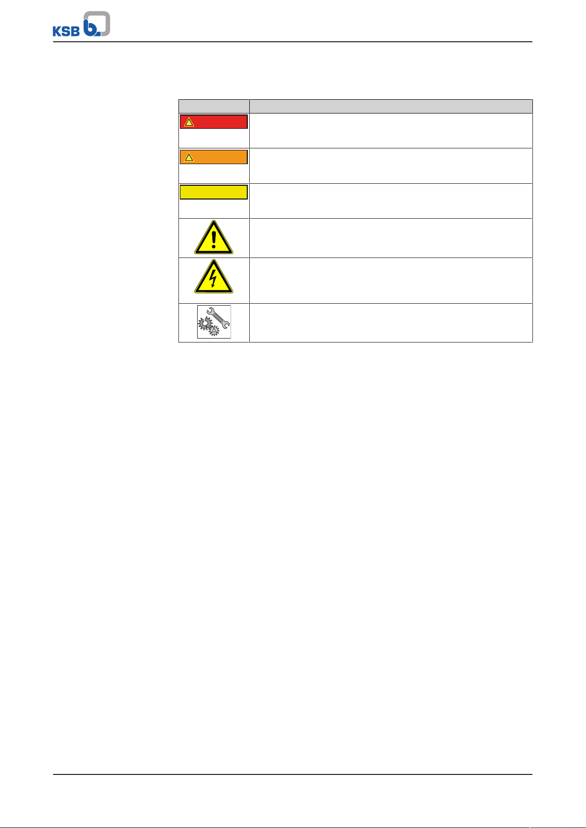
Table3: Definition of safety symbols/markings
Symbol Description
DANGER
This signal word indicates a high-risk hazard which, if not avoided,
will result in death or serious injury.
WARNING
This signal word indicates a medium-risk hazard which, if not
avoided, could result in death or serious injury.
CAUTION
This signal word indicates a hazard which, if not avoided, could
result in damage to the machine and its functions.
General hazard
In conjunction with one of the signal words this symbol indicates a
hazard which will or could result in death or serious injury.
Electrical hazard
In conjunction with one of the signal words this symbol indicates a
hazard involving electrical voltage and identifies information about
protection against electrical voltage.
Machine damage
In conjunction with the signal word CAUTION this symbol indicates
a hazard for the machine and its functions.
1983.844/02-EN
KSB Delta Solo
7 of 60
Page 8

2 Safety
!
DANGER
2 Safety
All the information contained in this section refers to hazardous situations.
In addition to the present general safety information the action-related safety
information given in the other sections must be observed.
2.1 General
▪ This operating manual contains general installation, operating and maintenance
instructions that must be observed to ensure safe operation of the system and
prevent personal injury and damage to property.
▪ Comply with all the safety instructions given in the individual sections of this
operating manual.
▪ The operating manual must be read and understood by the responsible specialist
personnel/operators prior to installation and commissioning.
▪ The contents of this operating manual must be available to the specialist
personnel at the site at all times.
▪ Information and markings attached directly to the product must always be
complied with and kept in a perfectly legible condition at all times. This applies
to, for example:
– Arrow indicating the direction of rotation
– Markings for connections
– Name plate
▪ The operator is responsible for ensuring compliance with all local regulations not
taken into account.
2.2 Intended use
▪ The pressure booster system must only be operated within the operating limits
described in the other applicable documents.
▪ Only operate pressure booster systems which are in perfect technical condition.
▪ Do not operate partially assembled pressure booster systems.
▪ The pressure booster system must only handle the fluids described in the product
literature of the respective design variant.
▪ Never operate the pressure booster system without the fluid to be handled.
▪ Observe the information on minimum flow rates specified in the product
literature (to prevent overheating, bearing damage, etc).
▪ Observe the maximum flow rates indicated in the data sheet or product
literature (to prevent overheating, cavitation damage, bearing damage, etc).
▪ Do not throttle the flow rate on the suction side of the pressure booster system
(to prevent cavitation damage).
▪ Consult the manufacturer about any other modes of operation not described in
the product literature.
2.2.1 Prevention of foreseeable misuse
▪ Never exceed the permissible application and operating limits specified in the
product literature regarding pressure, temperature, etc.
▪ Observe all safety information and instructions in this manual.
8 of 60
1983.844/02-EN
KSB Delta Solo
Page 9

2 Safety
2.3 Personnel qualification and personnel training
▪ All personnel involved must be fully qualified to install, operate, maintain and
inspect the product this manual refers to.
▪ The responsibilities, competence and supervision of all personnel involved in
transport, installation, operation, maintenance and inspection must be clearly
defined by the operator.
▪ Deficits in knowledge must be rectified by means of training and instruction
provided by sufficiently trained specialist personnel. If required, the operator can
commission the manufacturer/supplier to train the personnel.
▪ Training on the pressure booster system must always be supervised by specialist
technical personnel.
2.4 Consequences and risks caused by non-compliance with this manual
▪ Non-compliance with these operating instructions will lead to forfeiture of
warranty cover and of any and all rights to claims for damages.
▪ Non-compliance can, for example, have the following consequences:
– Hazards to persons due to electrical, thermal, mechanical and chemical
effects and explosions
– Failure of important product functions
– Failure of prescribed maintenance and servicing practices
– Hazard to the environment due to leakage of hazardous substances
1983.844/02-EN
2.5 Safety awareness
In addition to the safety information contained in this operating manual and the
intended use, the following safety regulations shall be complied with:
▪ Accident prevention, health regulations and safety regulations
▪ Explosion protection regulations
▪ Safety regulations for handling hazardous substances
▪ Applicable standards, directives and laws
2.6 Safety information for the operator/user
▪ Fit protective equipment (e.g. contact guards) supplied by the operator for hot,
cold or moving parts, and check that the equipment functions properly.
▪ Do not remove any protective equipment (e.g. contact guards) during operation.
▪ Eliminate all electrical hazards. (In this respect refer to the applicable national
safety regulations and/or regulations issued by the local energy supply
companies.)
▪ If shutting down the pump does not increase potential risk, fit an emergency-
stop control device in the immediate vicinity of the pump (set) during pump set
installation.
2.7 Safety information for maintenance, inspection and installation
▪ Modifications or alterations of the pressure booster system are only permitted
with the manufacturer's prior consent.
▪ Use only original spare parts or parts authorised by the manufacturer. The use of
other parts can invalidate any liability of the manufacturer for resulting damage.
▪ The operator ensures that maintenance, inspection and installation are
performed by authorised, qualified specialist personnel who are thoroughly
familiar with the manual.
▪ Carry out work on the pressure booster system during standstill only.
▪ The pump casing must have cooled down to ambient temperature.
▪ Pump pressure must have been released and the pump must have been drained.
KSB Delta Solo
9 of 60
Page 10
2 Safety
▪ When taking the pressure booster system out of service always adhere to the
procedure described in the manual.
▪ Decontaminate pressure booster systems which handle fluids posing a health
hazard.
▪ As soon as the work has been completed, re-install and/or re-activate any safety-
relevant and protective devices. Before returning the product to service, observe
all instructions on commissioning.
▪ Make sure the pressure booster system cannot be accessed by unauthorised
persons (e.g. children).
▪ Prior to opening the device, pull the mains plug and wait for at least 10minutes.
2.8 Unauthorised modes of operation
Always observe the limits stated in the product literature.
The warranty relating to the operating reliability and safety of the pressure booster
system supplied is only valid if the equipment is used in accordance with its intended
use. (ðSection2.2,Page8)
2.9 Electromagnetic compatibility (EMC)
2.9.1 Interference emission requirements
The EN61800-3 EMC product standard is relevant for electric variable speed drives/
control systems. It specifies all pertinent requirements and refers to the relevant
generic standards for complying with the EMC Directive.
Frequency inverters are commonly used by operators as a part of a system, plant or
machine assembly. It should be noted that the operator bears all responsibility for
the final EMC properties of the equipment, plant or installation.
A prerequisite or requirement for complying with the relevant standards or the limit
values and inspection/test levels referenced by them is that all information and
descriptions regarding EMC-compliant installation be observed and followed.
In accordance with the EMC product standard, the EMC requirements to be met
depend on the purpose or intended use of the frequency inverter. Four categories
are defined in the EMC product standard:
Table4: Categories of intended use
Category Definition Limits to EN55011
C1 Frequency inverters with a supply voltage under 1000V installed in the
Class B
first environment (residential and office areas).
C2 Frequency inverters with a supply voltage under 1000V installed in the
Class A, Group 1
first environment (residential and office areas) that are neither ready to
be plugged in/connected nor are mobile and must be installed and
commissioned by specialist personnel.
C3 Frequency inverters with a supply voltage under 1000V installed in the
Class A, Group 2
second environment (industrial environments).
C4 Frequency inverters with a supply voltage over 1000V and a nominal
current over 400A installed in the second environment (industrial
No borderline/
boundary
environments) or that are envisaged for use in complex systems.
The following limit values and inspection/test levels must be complied with if the
generic standard on interference emissions applies:
1)
1) An EMC plan must be devised.
10 of 60
KSB Delta Solo
1983.844/02-EN
Page 11

2 Safety
Table5: Classification of installation environment
Environment Generic standard Limits to EN55011
First environment (residential and office areas) EN/IEC61000-6-3
for private, business and commercial
environments
Second environment (industrial environments) EN/IEC61000-6-4
for industrial environments
The frequency inverter meets the following requirements:
Table6: EMC properties of the frequency inverter
Power
[kW]
≤ 11 ≤5 C1 Class B
The EN61800-3 standard requires that the following warning be provided for drive
systems that do not comply with category C1 specifications:
This product can produce high-frequency interference emissions that may necessitate
targeted interference suppression measures in a residential or office environment.
2.9.2 Line harmonics requirements
The product is a device for professional applications as defined by EN 61000-3-2. The
following generic standards apply when establishing a connection to the public
power grid:
▪ EN 61000-3-2
▪ EN 61000-3-12
Cable length
[m]
for symmetric, three-phase devices (professional devices with a total power of up
to 1kW)
for devices with a phase current of between 16A and 75A and professional
devices from 1kW up to a phase current of 16 A.
Category to EN 61800-3 Limits to EN55011
Class B
Class A, Group 1
1983.844/02-EN
2.9.3 Interference immunity requirements
In general, the interference immunity requirements for a frequency inverter hinge on
the specific environment in which the inverter is installed.
The requirements for industrial environments are therefore higher than those for
residential and office environments.
The frequency inverter is designed such that the immunity requirements for
industrial environments and, thus, the lower-level requirements for residential and
office environments, are met and fulfilled.
The following relevant generic standards are used for the interference immunity test:
▪ EN 61000-4-2: Electromagnetic compatibility (EMC)
– Part 4-2: Testing and measurement techniques – Electrostatic discharge
immunity test
▪ EN 61000-4-3: Electromagnetic compatibility (EMC)
– Part 4-3: Testing and measurement techniques – Radiated, radio-frequency,
electromagnetic field immunity test
▪ EN 61000-4-4: Electromagnetic compatibility (EMC)
– Part 4-4: Testing and measurement techniques – Electrical fast transient/burst
immunity test
▪ EN 61000-4-5: Electromagnetic compatibility (EMC)
– Part 4-5: Testing and measurement techniques – Surge immunity test
▪ EN 61000-4-6: Electromagnetic compatibility (EMC)
– Part 4-6: Testing and measurement techniques – Immunity to conducted
disturbances, induced by radio-frequency fields
KSB Delta Solo
11 of 60
Page 12
3 Transport/Temporary Storage/Disposal
3 Transport/Temporary Storage/Disposal
3.1 Checking the condition upon delivery
1. On transfer of goods, check each packaging unit for damage.
2. In the event of in-transit damage, assess the exact damage, document it and
notify KSB or the supplying dealer and the insurer about the damage in writing
immediately.
3.2 Transport
DANGER
Pressure booster system tipping over
Danger to life from falling pressure booster system!
▷ Never suspend the pressure booster system by its power cable.
▷ Do not lift the pressure booster system by its manifold.
▷ Observe the applicable local accident prevention regulations.
▷ Observe the information on weights, centre of gravity and fastening points.
▷ Use suitable and permitted transport equipment, e.g. crane, forklift or pallet
jack.
ü Transport equipment/ lifting equipment suitable for the corresponding weight
has been selected and is on hand.
1. Remove the packaging. Remove the caps from the connection openings.
2. Check for any in-transit damage.
3. Transport the pressure booster system to the place of installation.
4. Detach the pressure booster system from the pallet using a suitable tool.
5. Attach the pressure booster system to the lifting equipment as illustrated.
6. Lift it off the wooden skids. Dispose of the wooden skids.
7. Carefully place down the pressure booster system at the site of installation.
3.3 Storage/preservation
CAUTION
Damage during storage due to frost, moisture, dirt, UV radiation or vermin
Corrosion/contamination of pressure booster system!
▷ Store the pressure booster system in a frost-proof room. Do not store outdoors.
CAUTION
Wet, contaminated or damaged openings and connections
Leakage or damage of the pressure booster system!
▷ Only open the openings of the pressure booster system at the time of
installation.
12 of 60
NOTE
Rotate the shaft by hand every three months, e.g. via the motor fan.
1983.844/02-EN
If commissioning is to take place some time after delivery, the following measures
are recommended when storing the pressure booster system:
KSB Delta Solo
Page 13
3 Transport/Temporary Storage/Disposal
Store the pressure booster system in a dry, protected room where the atmospheric
humidity is as constant as possible.
Table7: Ambient conditions for storage
Ambient condition Value
Relative humidity 50% maximum
Ambient temperature 0°C to +40°C
▪ Frost-free
▪ Well-ventilated
3.4 Return to supplier
1. Drain the pressure booster system as per operating instructions.
2. Always flush and clean the pressure booster system, particularly if it has been
used for handling noxious, explosive, hot or other hazardous fluids.
3. If the pressure booster system has handled fluids whose residues could lead to
corrosion damage in the presence of atmospheric humidity or could ignite upon
contact with oxygen, the pressure booster system must also be neutralised and
treated with anhydrous inert gas to ensure drying.
4. Always complete and enclose a certificate of decontamination when returning
the pressure booster system. (ðSection12,Page57)
Always indicate any safety and decontamination measures taken.
NOTE
If required, a blank certificate of decontamination can be downloaded from the
following web site: www.ksb.com/certificate_of_decontamination
3.5 Disposal
WARNING
Fluids handled, consumables and supplies which are hot and/or pose a health
hazard
Hazard to persons and the environment!
▷ Collect and properly dispose of flushing fluid and any fluid residues.
▷ Wear safety clothing and a protective mask if required.
▷ Observe all legal regulations on the disposal of fluids posing a health hazard.
1. Dismantle the pressure booster system.
Collect greases and other lubricants during dismantling.
2. Separate and sort the pump materials, e.g. by:
- Metals
- Plastics
- Electronic waste
- Greases and other lubricants
3. Dispose of materials in accordance with local regulations or in another
controlled manner.
1983.844/02-EN
KSB Delta Solo
13 of 60
Page 14
3 Transport/Temporary Storage/Disposal
Electrical or electronic equipment marked with the adjacent symbol must not be
disposed of in household waste at the end of its service life.
Contact your local waste disposal partner for returns.
If the used electrical or electronic equipment contains personal data, the operator is
responsible for deleting it before the equipment is returned.
14 of 60
1983.844/02-EN
KSB Delta Solo
Page 15
4 Description
ID PN
Prod. IP
RDP PO
U Kalkovenweg 13
F Alphen a/d Rijn, NL
Imax www.ksb.com
KSB B. V.
Made in NL
KSB Delta Solo 1/1508
SVP
12345678
33A
50Hz
3x400V
PT
06/2018 1234567-01
123456789
54
10
1
14
13
12
6
11
10
9
8
7
2
5
43
4 Description
4.1 General description
▪ Pressure booster system
4.2 Product information as per Regulation No. 1907/2006(REACH)
For information as per chemicals Regulation (EC) No. 1907/2006 (REACH), see http://
www.ksb.com/reach.
4.3 Description
Example: KSB Delta Solo 1/1508 SVP
Table8: Designation key
Code Description
KSB Delta Solo Type series
1 Number of pumps
15 Size
08 Number of stages
SVP Design
SVP Pressure booster system with variable speed system and KSB
SuPremE motor
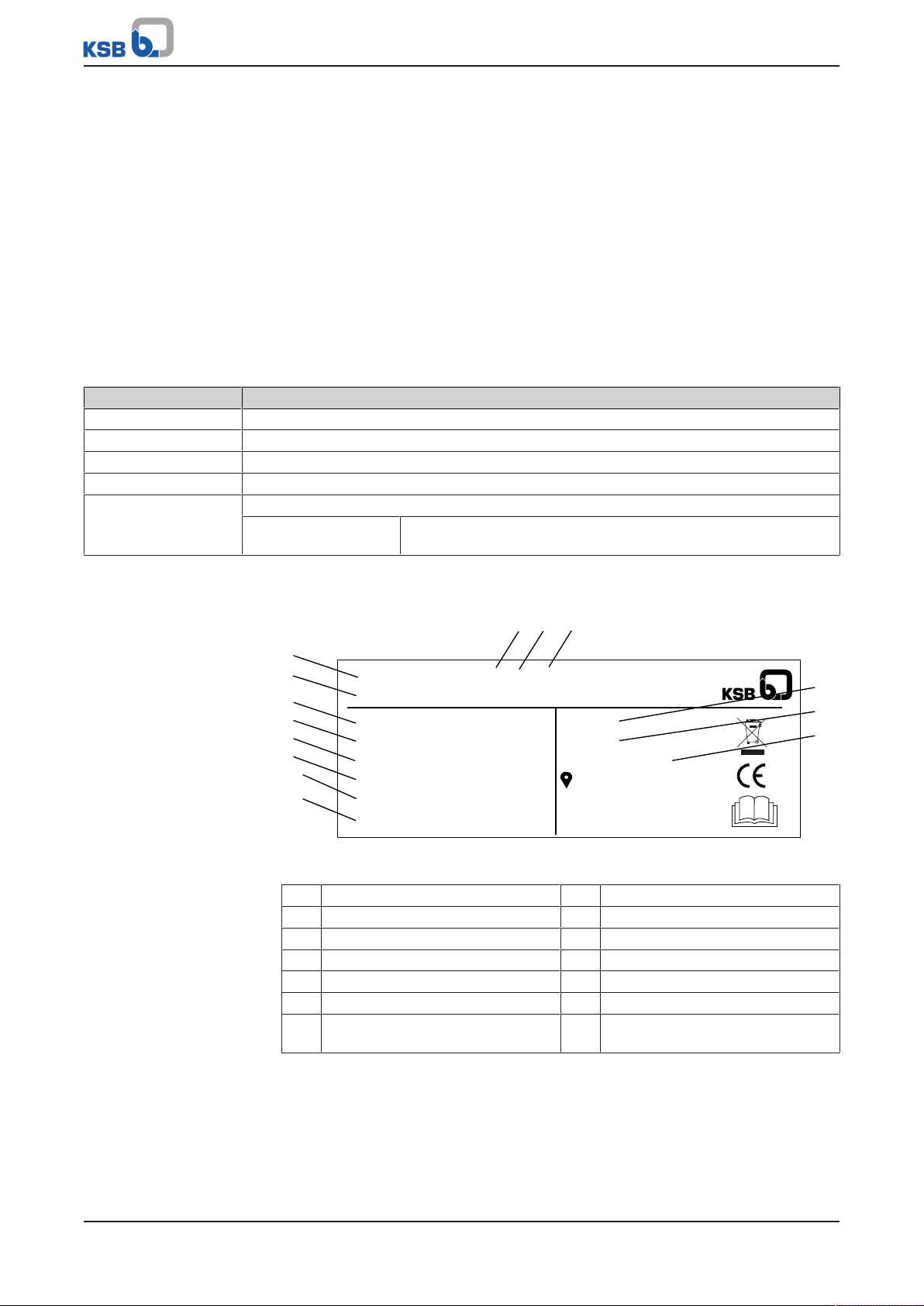
4.4 Name plate
Fig.1: Name plate (example)
1 Type series 8 Dry running protection
2 Design 9 Power supply voltage
3 Number of pumps 10 Power supply frequency
4 Size 11 Maximum current input
5 Number of pump stages 12 Max. operating pressure
6 Serial number 13 Enclosure
7 Month of production/ year of
4.5 Design details
1983.844/02-EN
Design
▪ Fully automatic pressure booster system
▪ Variable speed operation
▪ Baseplate-mounted
KSB Delta Solo
production, consecutive number
14 Order number
15 of 60
Page 16
4 Description
1
2
3
4
▪ Hydraulic components made of stainless steel / brass
▪ Check valve
▪ Discharge-side, direct-flow membrane-type accumulator, approved for drinking
water
▪ Pressure gauge
▪ Integrated dry running protection
▪ Pressure transmitters on the inlet side and discharge side
▪ Vibration damping
Installation
▪ Stationary dry installation
Drive
▪ Electric motor
▪ Efficiency class IE4/IE5 to IECTS60034-30-2:2016
▪ IP54 enclosure
Automation
▪ Frequency inverter
▪ Control panel (display, keys, LEDs, service interface)
▪ Control unit (IP54 enclosure)
▪ Fault message signalling contact
▪ Operation signalling contact
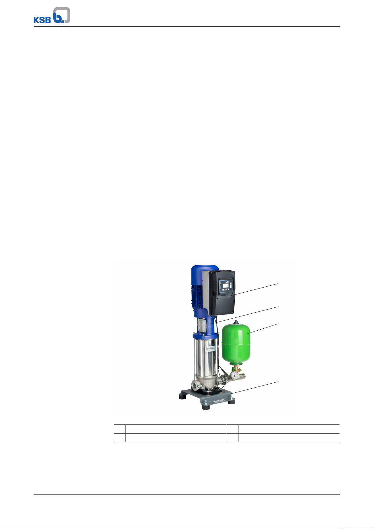
4.6 Configuration and function
Fig.2: Configuration
1 Control unit 3 Membrane-type accumulator
2 Pump 4 Baseplate
Design The fully automatic pressure booster system pumps the fluid to the consumer
installations in the set pressure range with a vertical high-pressure pump (2) (variable
speed version).
1983.844/02-EN
16 of 60
KSB Delta Solo
Page 17

4 Description
Function The pump (2) is controlled and monitored by a motor-mounted frequency inverter.
As the demand increases or decreases, the pump is started and stopped
automatically.
The standard setting is for the pressure booster system to start automatically as a
function of pressure; the actual pressure is measured by an analog pressure
measuring device (pressure transmitter).
As long as the pressure booster system is in operation, the pump is started and
stopped as a function of demand (standard setting). In this way it is ensured that the
pump operates only in line with actual demand.
The use of this variable speed pump reduces wear as well as the frequency of pump
starts. A fault is output, which can be reported via volt-free contacts (e.g. to the
control station).
If the demand drops towards 0, the pressure booster system slowly runs down to the
stop point.
The pressure booster system is designed with integrated electronic dry running
protection.
A digital lack-of-water display can be connected at the corresponding contacts.
During commissioning and after every power failure, the pressure booster system fills
the piping system slowly to prevent any damage to the piping by surge pressure.
If the pump has not been in operation for 24 hours, a test run is initiated.
4.7 Scope of supply
Depending on the model, the following items are included in the scope of supply:
Pressure booster system
▪ 1 vertical high-pressure centrifugal pump with oval flange
▪ Powder-coated / epoxy resin-coated steel baseplate
▪ Check valve
▪ Discharge- side gate valve
▪ Suction-side gate valve
▪ Suction-side manifold and discharge-side manifold made of stainless steel
▪ Pressure transmitter on the discharge side
▪ Pressure gauge
▪ Dry running protection on the inlet pressure side
▪ Discharge-side, direct-flow membrane-type accumulator, approved for drinking
water
Control unit
▪ IP54 enclosure
▪ Control panel (display, keys, LEDs, service interface)
▪ Three LEDs signalling the operating status
▪ Lockable master switch (repair switch)
▪ Frequency inverter
1983.844/02-EN
2) Multiple pump systems only
4.8 Dimensions
For dimensions refer to the outline drawings of the pressure booster system.
4.9 Terminal diagram
For the terminal assignment refer to the circuit diagram.
2)
KSB Delta Solo
17 of 60
Page 18

4 Description
1
2
4.10 Potential equalisation
A terminal marked with the earth symbol is provided at the power connection for
connecting a PE conductor.
Fig.3: PE connection
1 Earthing terminal 2 Location of power connection
18 of 60
1983.844/02-EN
KSB Delta Solo
Page 19

5 Installation at Site
5 Installation at Site
5.1 Checks to be carried out prior to installation
WARNING
Installation on mounting surfaces which are unsecured and cannot support the
load
Personal injury and damage to property!
▷ Use a concrete of compressive strength class C12/15 which meets the
requirements of exposure class X0 to EN206-1.
▷ The mounting surface must have set and must be completely horizontal and
even.
▷ Observe the weights indicated.
NOTE
The anti-vibration mounts of the pressure booster system provide adequate
insulation against solid-borne noise.
Thanks to level-adjustable feet (KSB accessory) the pressure booster system can also
be installed in a horizontal position on uneven floors.
For pressure booster systems with pumps, Movitec 2, 4, 6, 10, 15 level-adjustable feet
are available as accessories.
NOTE
Do not install pressure booster systems next to sleeping or living quarters.
NOTE
The installation room must provide for suitable drainage.
Before beginning with the installation check the following:
▪ All structural work required has been checked and prepared in accordance with
the dimensions in the outline drawing.
▪ The pressure booster system can be operated on the power supply network
according to the data on the name plate.
▪ The place of installation is frost-free.
▪ The place of installation can be locked.
▪ The place of installation is well-ventilated.
▪ A suitably dimensioned drain connection (e.g. leading to a sewer) is available.
▪ If expansion joints are used, take note of their creep resistance. Expansion joints
must be easily replaceable.
1983.844/02-EN
5.2 Installing the pressure booster system
WARNING
Top-heavy pressure booster system
Risk of personal injury by pressure booster system tipping over!
▷ Pressure booster systems awaiting final installation must be secured against
tipping over.
▷ Firmly anchor the pressure booster system.
KSB Delta Solo
19 of 60
Page 20

5 Installation at Site
1952:116
1
NOTE
To prevent the transmission of piping forces and solid-borne noise, installing
expansion joints with length-limiters is recommended.
ü The pressure booster system’s packaging has been removed.
ü A suitable installation site has been selected that meets the requirements.
ü Sufficient clearance in all directions is provided for servicing work.
1. Mark out the anchoring holes on the floor as shown in the outline drawing.
2. Drill the holes (max. diameter: 12mm).
3. Insert plug fixings of appropriate size.
4. Place the pressure booster system in its correct installation position.
5. Use suitable bolts to firmly anchor the pressure booster system.
5.3 Mounting the accumulator
CAUTION
Dirt in the pressure booster system
Damage to the pump sets!
▷ Clean the accumulator before filling it.
ü The original operating manual of the pressure booster system is on hand.
1. Mechanically and electrically connect the accumulator in accordance with the
original operating manual supplied.
5.4 Connecting the piping
CAUTION
Air pockets in suction line
Pressure booster system cannot prime!
▷ Lay the pipe with a continuously rising slope.
Fig.4: Correct piping connection
1 Suction lift operation
1. Mechanically support the suction head line on site to provide for absorption of
mechanical forces.
2. Install the piping without transmitting any stresses and strains.
3. Connect the piping to the distribution lines on the inlet side and discharge side.
20 of 60
NOTE
For single-pump systems, the shut-off valves must be fitted directly at the system's
suction-side connection and discharge-side connection, respectively. This will enable
straightforward replacement and servicing.
KSB Delta Solo
1983.844/02-EN
Page 21

5 Installation at Site
5.4.1 Fitting an expansion joint (optional)
DANGER
Sparks and radiant heat
Fire hazard!
▷ Take suitable precautions to protect the expansion joint if any welding work is
carried out.
CAUTION
Leaking expansion joint
Flooding of installation room!
▷ Do not apply any paint to the expansion joint.
▷ Keep the expansion joint clean.
▷ Regularly check for cracks or blisters, exposed fabric or other defects.
ü Sufficient clearance in all directions is provided for checking the expansion joint.
ü The expansion joint is not insulated along with the pipeline insulation.
1. The expansion joint has a length limiter with solid-borne sound insulation.
2. Install the expansion joint in the piping free of twist or distortion. Never use the
expansion joint to compensate for misalignment or mismatch of the piping.
3. Evenly tighten the bolts crosswise. The ends of the bolts must not protrude from
the flange.
Example p
5.4.2 Fitting the pressure reducer (optional)
NOTE
A pipe length of approximately 600 mm must be provided on the inlet side to
accommodate a pressure reducer, if necessary.
NOTE
A pressure reducer must be installed if the inlet pressure fluctuation is too high for
the pressure booster system to operate as intended or if the total pressure (inlet
pressure and shut-off head) exceeds the design pressure.
The inlet pressure (p
5m is required for the pressure reducer to function properly. This means that the
pressure reducer must be mounted 5m higher than the pressure booster system. The
pressure drops by about 0.1bar per metre of height difference. Alternatively, the
pressure reducer can be subjected to a pressure of 0.5 bar.
=4bar
inl
Minimum pressure gradient=5m ≙ 0.5bar
Downstream pressure:4bar - 0.5bar = 3.5bar.
ü A minimum pressure gradient of 5m is available.
1. Install the pressure reducer in the pipe on the inlet side.
) varies between 4and 8bar. A minimum pressure gradient of
inl
1983.844/02-EN
5.5 Fitting the dry running protection device
Install the dry running protection device supplied together with the pressure booster
system as a separate, non-fitted accessory, or supplied at a later date for retrofitting,
in accordance with its operating instructions and connect it to the switchgear and
controlgear assembly.
The switchgear and controlgear assembly is provided with the requisite inputs.
1. Remove the front cover to access the terminal strip.
KSB Delta Solo
21 of 60
Page 22

400V/ 3~ variant with
L1 L2 L3
LINE
PE U V W
MOTOR
PTC
MOTOR
PE
-
1
2
3
4
BR
+
6
1
2
DI-EN
+24V
GND
DI3
DI2
DI1
+24V
DICOM
AO-GND
AO
AIN2
NO1
+24V
GND
COM1
+24V
B7
B
8
B9
B10
GND
GND
AIN1
+24V
NO
2
2
+24V
C1
C2
C
3
GND
B1
B2B3B4
B
5
B6
A1A2A3
A4
A5A6A7
A8
A9
A
10
C
4
2relays
5 Installation at Site
Fig.5: Overview of terminal strips for 400V/ 3~ variant with 1relay
1 Connection to power supply
2 Control cables
network and motor
In the case of direct connection (direct connection of the pump system to the
drinking water supply line of the public water supply system):
1. Use a wire jumper to connect DI1 (B4) and +24V (B3).
ð When this connection type is used, monitoring by the suction-side pressure
sensor protects the pump system against lack of water.
In the case of indirect connection (connection to an unpressurised drinking water
reservoir (water tank)):
1. Remove the wire jumper between DI1 (B4) and +24V (B3). Connect an external
dry running protection device (e.g. a float switch) in its place.
ð When this connection type is used, the lack-of-water function must be
adjusted.
Adjusting the lack-of-water function:
1. Log in at the frequency inverter using the customer login (standard: 0000). Open
parameter 3 "Settings".
2. Open parameter 3-9-11 "Lack-of-water function". Adjust parameters 3-9-11-5
and 3-9-11-6 .
3. If a single-pump pressure booster system is operated with an indirect connection
(e.g. water tank), set parameter 3-9-11-4 to "OFF".
5.6 Electrical connection
DANGER
Electrical connection work by unqualified personnel
Danger of death from electric shock!
▷ Always have the electrical connections installed by a trained and qualified
electrician.
▷ Observe regulations IEC60364.
22 of 60
WARNING
Incorrect connection to the mains
Damage to the mains network, short circuit!
▷ Observe the technical specifications of the local energy supply companies.
NOTE
Installing a motor protection device is recommended.
KSB Delta Solo
1983.844/02-EN
Page 23

5 Installation at Site
NOTE
If a residual current device is installed, observe the operating manual for the
frequency inverter.
Lightning protection
▪ Electrical installations must be protected against overvoltage (compulsory since
14December2018) (see DINVDE0100-443 (IEC60364-4-44:2007/A1:2015,
modified) and DIN VDE 0100-534 (IEC 60364-5-53:2001/A2:2015, modified).
Whenever modifications are made to existing installations, retrofitting a surge
protective device (SPD) in accordance with VDE is mandatory.
▪ A maximum cable length of 10metres should not be exceeded between the
surge protective device (usually type 1, internal lightning protection) installed at
the service entrance and the equipment to be protected. For longer cables,
additional surge protective devices (type 2) must be provided in the subdistribution board upstream of the equipment to be protected or directly in the
equipment itself.
▪ The associated lightning protection concept must be provided by the operator or
by a suitable provider commissioned by the operator. Surge protective devices
can be offered for the control units on request.
Wiring diagram
The wiring diagrams are located in the control cabinet, which is where they must be
stored.
The product literature of the switchgear and controlgear assembly supplied with the
system includes a list of the electrical components installed. When ordering spare
parts for electrical components, always indicate the number of the wiring diagram.
Terminal assignment
For the terminal assignment refer to the wiring diagram.
5.6.1 Sizing the power cable
Determine the cross-section of the power cable based on the total rated power
required.
5.6.2 Connecting the pressure booster system
Plug the mains plug into a suitable socket. Observe the data on the name plate.
5.6.2.1 Fitting an expansion joint (optional)
DANGER
Sparks and radiant heat
Fire hazard!
▷ Take suitable precautions to protect the expansion joint if any welding work is
carried out.
1983.844/02-EN
KSB Delta Solo
23 of 60
Page 24

5 Installation at Site
CAUTION
Leaking expansion joint
Flooding of installation room!
▷ Do not apply any paint to the expansion joint.
▷ Keep the expansion joint clean.
▷ Regularly check for cracks or blisters, exposed fabric or other defects.
ü Sufficient clearance in all directions is provided for checking the expansion joint.
ü The expansion joint is not insulated along with the pipeline insulation.
1. The expansion joint has a length limiter with solid-borne sound insulation.
2. Install the expansion joint in the piping free of twist or distortion. Never use the
expansion joint to compensate for misalignment or mismatch of the piping.
3. Evenly tighten the bolts crosswise. The ends of the bolts must not protrude from
the flange.
5.6.2.2 Fitting the pressure reducer (optional)
NOTE
Example p
A pipe length of approximately 600 mm must be provided on the inlet side to
accommodate a pressure reducer, if necessary.
NOTE
A pressure reducer must be installed if the inlet pressure fluctuation is too high for
the pressure booster system to operate as intended or if the total pressure (inlet
pressure and shut-off head) exceeds the design pressure.
The inlet pressure (p
5m is required for the pressure reducer to function properly. This means that the
pressure reducer must be mounted 5m higher than the pressure booster system. The
pressure drops by about 0.1bar per metre of height difference. Alternatively, the
pressure reducer can be subjected to a pressure of 0.5 bar.
=4bar
inl
Minimum pressure gradient=5m ≙ 0.5bar
Downstream pressure:4bar - 0.5bar = 3.5bar.
ü A minimum pressure gradient of 5m is available.
1. Install the pressure reducer in the pipe on the inlet side.
5.6.3 Connecting the dry running protection device
ü The original operating manual of the dry running protection device is on hand.
1. Fit the dry running protection device in accordance with the supplied original
operating manual. Connect it in the control unit in accordance with the supplied
original operating manual.
) varies between 4and 8bar. A minimum pressure gradient of
inl
24 of 60
1983.844/02-EN
KSB Delta Solo
Page 25

6 Commissioning/Start-up/Shutdown
6 Commissioning/Start-up/Shutdown
6.1 Commissioning/Start-up
6.1.1 Prerequisites for commissioning/start-up
Before commissioning/start-up of the pressure booster system make sure that the
following requirements are met:
▪ The pressure booster system has been properly connected to the electric power
supply and is equipped with all protection devices.
▪ All relevant VDE standards and/or regulations applicable in the country of use are
complied with.
▪ The dry running protection device has been installed.
CAUTION
Dry running of pump
Damage to the pump/pressure booster system!
▷ If no dry running protection device is connected when commissioning takes
place, pressure booster systems in manual or test run mode will be stopped
automatically after approx. 10 seconds. If the dry running protection terminal is
disabled by means of a bridge, the operator shall assume responsibility for any
dry running that might occur.
NOTE
The competent authorities must be informed in due time prior to commissioning/
test running the system.
6.1.2 Dry running protection
Pressure booster systems are fitted with a dry running protection device.
A float switch whose volt-free contact closes the circuit in upper float position can be
connected to the control system as dry running protection. Follow the float switch
manufacturer's instructions on how to set the float switch levels.
6.1.3 Commissioning/start-up of pressure booster system
NOTE
Prior to its delivery, the pressure booster system will be tested hydraulically with
water and then drained again. For technical reasons the presence of some residual
water is unavoidable.
Prior to commissioning/start-up observe EN806. After prolonged standstill periods,
flushing or professional disinfection is recommended. For extensive or branched
piping systems, flushing the pressure booster system can be restricted to a limited
area.
CAUTION
1983.844/02-EN
Foreign matter in the piping
Damage to the pump / pressure booster system!
▷ Before commissioning/starting up or functional check running the pressure
booster system, make sure that there is no foreign matter in the pressure
booster system or piping.
KSB Delta Solo
25 of 60
Page 26

6 Commissioning/Start-up/Shutdown
NOTE
Commissioning of the pressure booster system - even test running - shall only be
carried out in full compliance with all pertinent VDE (German Association of
Electrical Engineers) regulations.
CAUTION
Operation without the fluid to be handled
Damage to the pump sets!
▷ Prime the pressure booster system with the fluid to be handled.
ü The pipe unions between the pump and the piping have been re-tightened.
ü Flange connections have been firmly tightened.
ü The cooling air inlet openings and cooling air outlet openings at the motor are
unobstructed.
ü All shut-off valves of the pressure booster system are open.
ü The pre-charge pressure of the membrane-type accumulator has been checked.
1. Disconnect the mains plug from the power supply.
2. Provide connection to power supply.
3. Open/loosen the vent plugs on the pump (refer to the pump's installation/
operating manual).
4. Slowly open the inlet-side shut-off element and prime the pressure booster
system until the fluid to be handled escapes through all vent holes.
5. Close and slightly tighten the pump vent plugs.
6. Switch on all motor protection switches.
7. Set the manual-0-automatic selector switch (if any) to Automatic.
8. Switch on the master switch.
9. Open the discharge-side shut-off element.
10. After the pump set has been run once, switch it off and loosen the vent plugs
again to let any remaining air escape.
11. Tighten the vent plug firmly.
12. Verify that the pump is running smoothly.
13. Close the discharge-side shut-off element for a short period in order to verify
that the pump reaches the shut-off head.
14. Close the discharge-side shut-off element, causing the pump to stop.
26 of 60
NOTE
Minor leakage of the mechanical seals during commissioning is normal and will
cease after a short period of operation.
6.2 Start-up
NOTE
The pressure booster system is factory-set to the data indicated on the name plate.
Standard design
ü The pressure booster system has been primed and vented.
1. Switch on the master switch.
ð The green LED lights up and signals the system's readiness for operation.
KSB Delta Solo
1983.844/02-EN
Page 27

6 Commissioning/Start-up/Shutdown
Additional instruments
ü The pressure booster system has been primed and vented.
1. Set the manual-0–automatic selector switch to automatic.
ð The green LED lights up and signals the system's readiness for operation.
6.3 Checklist for commissioning/start-up
Table9: Checklist
Actions Done
1 Read the operating manual.
2 Compare the power supply data against the name plate data.
3 Check the earthing system (taking measurements).
4 Check the mechanical connection to the water mains.
Re-tighten the flange bolting and pipe unions.
5 Check the pre-charge pressure.
6 Prime and vent the pressure booster system from the inlet side.
7 Check inlet pressure.
8 Check whether all cables are still firmly connected to the terminals inside the control unit.
9 Check the start and stop pressure; re-adjust if necessary.
10 Test the proper function of the lack-of-water and dry-running protection equipment. If not
fitted, make a relevant note in the acceptance report.
11 Vent the pump for a second time after it has been running for 5 to 10 minutes.
12 Set all switches to automatic.
13 Record all system conditions that do not correspond to our specifications or to the purchase
order in the commissioning report (i.e. no dry running protection or inlet pressure + max.
pressure of pressure booster system higher than 16bar).
14 Complete the commissioning report together with the operator/user and instruct the operator/
user as to the function of the unit.
1983.844/02-EN
6.4 Shutdown
NOTE
As long as the pressure booster system is out of operation, water is supplied directly
at p
through the pressure booster system.
inl
Set the master switch to "0".
NOTE
Drain the pressure booster system for prolonged shutdown.
KSB Delta Solo
27 of 60
Page 28

7 Operation
1
3
4
5
2
AUTO
1/min
OFFOFF
MAN
AUTO
1/min
m h kW
A V Hz
% °C bar
1 2
3
4
5
6
7
8
9
7 Operation
7.1 Standard control panel
Fig.6: Standard control panel
Table10: Description of standard control panel
Item Description Function
1 Service interface Optical interface
2 LED traffic light function The traffic light function provides information about the system's
operating status.
3 Display Displays information on frequency inverter operation
4 Operating keys Toggling operating modes
5 Navigation keys Navigation and parameter setting
7.1.1 Display
28 of 60
Fig.7: Main screen (example)
1 Operating point display
2 Type of control
3 Display of the current operating mode
KSB Delta Solo
1983.844/02-EN
Page 29

7 Operation
AUTO
AUTO
bar
AUTO
bar
AUTO
1/min
4 Units
5 Menu, parameter number, parameter values
6 Log in as customer
7 Active wireless connection
The wireless icon illuminates when the Bluetooth module is inserted. The
wireless icon flashes when communication takes place.
8 Single/dual pump
9 Rotational speed 0-100%
Table11: Menu, parameter number, parameter values, messages
Display Function
Menu example: Open-loop Control (1-3):
▪ The letter S is used as the first character to identify a menu.
▪ The second character identifies the first menu level, i.e. Operation S1-x-x-x,
Diagnosis S2-x-x-x, Settings S3-x-x-x and Information S4-x-x-x.
▪ The wrench icon shows that you have logged in as a customer.
Menu example: Open-loop
Control
Parameter number example: Setpoint (Closed-loop Control) (1-3-2):
▪ The letter P is used as the first character to identify a parameter number.
▪ The following characters show the parameter number.
▪ The wrench icon shows that you have logged in as a customer.
Parameter number example:
Setpoint (Closed-loop Control)
Parameter value example:
Setpoint (Closed-loop Control)
Message example: Dry running
Parameter value example: Setpoint (Closed-loop Control) (1-3-2) set to 4 bar:
▪ If a parameter value can be edited, the digit flashes.
▪ The wrench icon shows that you have logged in as a customer.
Message example: Dry running (E13):
▪ A message is identified by the letter E (Error) and a unique number.
1983.844/02-EN
KSB Delta Solo
29 of 60
Page 30

Table12: Assignment of keys
ESC
OK
MAN
OFF
AUTO
MAN
ESC
OK
Key Function
Arrow keys:
▪ Move up/down in the menu options.
▪ Increase/decrease a numerical value. (When an arrow key is pressed and held down, the
response repeats in ever shorter intervals.)
Escape key:
▪ Delete/reset entry
(the entry is not saved).
▪ Move up one menu level.
OK key:
▪ Confirm settings.
▪ Confirm menu selection.
▪ Move to the next digit when entering numerals.
▪ Message display: Acknowledge alert.
▪ Measured value display: Go to Favourites menu.
MAN operating key:
▪ Starts the frequency inverter in manual operating mode.
7 Operation
OFF operating key:
▪ Stops the frequency inverter.
AUTO operating key:
▪ Switches to automatic operating mode.
Manual mode via control panel
NOTE
After a power failure, the frequency inverter reverts to the OFF operating mode.
Manual mode must be restarted.
Table13: Assignment of keys for manual mode
Key Function
MAN operating key:
▪ When switching the operating mode from AUTO to MAN, the current operating speed is
used as control value (Manual) 1-3-4 and is displayed accordingly. The control point
1-3-10 must be set to Local.
▪ When switching the operating mode from OFF to MAN, the frequency inverter operates
at minimum speed. The control point 1-3-10 must be set to Local.
▪ If the control value (Manual) 1-3-4 is defined via an analog input, the analog input speed
is accepted.
Arrow keys:
▪ Pressing the arrow keys changes and immediately accepts the control value (Manual)
1-3-5. Making a change using the arrow key has a direct effect even when not confirmed
with OK. The speed can only be changed between the set minimum speed and the
maximum speed.
30 of 60
ESC/OK key:
▪ Press the OK or ESC key to go from digit to digit. Press the ESC key to go back. Changes
are rejected. Pressing the OK key for the right-hand digit takes you back to the main
screen.
KSB Delta Solo
1983.844/02-EN
Page 31

7 Operation
AUTO
Hz
AUTO
1/min
AUTO
kW
AUTO
A
AUTO
Hz
AUTO
1/min
AUTO
kW
AUTO
A Hz
ESC
OK
ESC
OK
ESC
OK
ESC
OK
1 2
43
5
87
6
7.1.2 Main screen
The main screen shows factory default operating values.
Fig.8: Selecting and displaying operating values on the main screen
1 Parameter number for speed (1-2-1-1)
2 Current speed [rpm]
3 Parameter number for motor input power (1-2-1-2)
1983.844/02-EN
4 Current power input of motor in kW
5 Parameter number for motor current (1-2-1-5)
6 Current motor current in A
KSB Delta Solo
31 of 60
Page 32

7 Operation
AUTO
1/min
AUTO
ESC
OKESC
+
AUTO
1/min
1 2
7 Parameter number for output frequency (1-2-1-7)
8 Current output frequency in Hz
If a message (alert, warning or information) is currently active, it will be displayed on
the main screen.
Fig.9: Message display
A message is identified by the letter E (Error) and a unique number (see list of all
messages in the Annex). The traffic light function shows whether the message is an
alert (red LED), a warning (amber LED) or just information (green LED).
Messages are acknowledged by pressing OK. Acknowledged and gone messages are
listed in the message history in Menu 2 – Diagnosis.
NOTE
If the motor standstill heater has been switched on, the display alternates between
the measured value and the letter H.
7.1.3 Settings menu
NOTE
The standard control panel is designed to be used for simple settings only (e.g.
setting the setpoint). We recommend using the KSB ServiceTool for more extensive
configuration tasks.
Opening the Settings menu: Press and hold the ESC key and press OK.
Fig.10: Switch to the settings menu
1 Main screen 2 Settings menu
The wrench icon indicates that the settings menu is called up and a value can be
edited.
The parameter numbers identify the navigation path, which helps you find a
particular parameter quickly and easily. The first digit of the parameter number
indicates the first menu level, which is called up directly via the four menu keys.
32 of 60
KSB Delta Solo
1983.844/02-EN
Page 33

7 Operation
7.1.3.1 Menu: Operation
The Operation section contains all information required for operating the machine
and the process. This includes:
▪ Login to device with password
▪ Operating and measured values for motor, frequency inverter, pump and system
▪ Setpoints and control values
▪ Energy meter and operating hours
7.1.3.1.1 Access levels
Three access levels have been defined to prevent unintentional or unauthorised
access to frequency inverter parameters:
Table14: Access levels
Access level Description
Standard (No Login) Access without password entry.
Customer Access level for the expert user with access to all parameters required for
commissioning
Customer service Access level for service personnel.
If a parameter's access level is not explicitly specified, the parameter is always
assigned the Customer access level.
Table15: Access level parameters
Parameter Description Possible settings Factory setting
1-1-1 Customer Login
Log in as customer
Customer service parameters can only be accessed using the KSBServiceTool and the
appropriate dongle.
0000...9999 0000
NOTE
If no keys are pressed for five minutes, the system will automatically return to the
Standard access level.
The password can be changed after entering the factory default password.
Table16: Parameter for changing the password (requires use of the KSBServiceTool)
Parameter Description Possible settings Factory setting
1-1-5 Customer Access ID
Changing the customer access ID
7.1.3.2 Menu: Diagnosis
In the Diagnosis section, the user is provided with information about faults and
warning messages that pertain to the pump set or process. The frequency inverter
can be in fault (standstill) or warning (operational) status. The user can also find
previous messages in the history.
0000...9999 -
1983.844/02-EN
Messages
All monitoring and protective functions trigger warnings or alerts. These are
signalled via the amber or red LED of the LED traffic light function.
A corresponding message is output on the control panel display. If more than one
message is output, the last one is displayed. Alerts have priority over warnings.
Pending messages If a message has occurred and been acknowledged but has not gone, this message
will be listed in the Pending Messages menu. All current messages can be displayed in
the Diagnosis menu under Pending Messages (2-1). Active warnings and alerts can
also be connected to the relay outputs.
KSB Delta Solo
33 of 60
Page 34

7 Operation
Message history Only messages that have come, been acknowledged, and gone are listed in the
message history. The message history can be viewed by selecting the Message History
parameter 2-2. The last 100 messages are listed here. You can use the arrow keys and
the OK key to select an entry from the list.
Acknowledging and resetting messages
NOTE
Depending on the combination of settings, the frequency inverter could
conceivably restart automatically after acknowledgement/reset or when the cause
of the malfunction or fault has been eliminated.
Acknowledgement Messages can be acknowledged once the cause has been rectified. Messages can be
acknowledged individually in the Diagnosis menu. A message can also be
acknowledged via a digital input. Digital input 2 is defaulted for this purpose.
Overview of warnings and alerts (ðSection9,Page42)
Messages can be acknowledged as follows:
Table17: Acknowledgement types for messages
Property of message Type of acknowledgement
Self-acknowledging Message is automatically acknowledged if condition for message no longer applies.
Automatic
acknowledgement
(configurable)
Partially automatic
acknowledgement
No automatic
acknowledgement
Time stamp If a message is not acknowledged and its condition comes and goes several times in
Users can choose between automatic acknowledgement and manual
acknowledgement.
Alerts that are partially acknowledged automatically carry out automatic
acknowledgement in increasingly large intervals after the alert condition no longer
applies. If the alert occurs repeatedly within a specific time window, automatic
acknowledgement is suspended.
As soon as the alarm condition of a pending alert no longer exists, the time interval is
started. When this interval expires, automatic acknowledgement takes place.
If the alert occurs again within 30seconds after the time interval has started, the
interval is extended by one increment. Should this not be the case, the previous
(shorter) time interval is reverted to and corresponding action is taken again in
30seconds. The time intervals are 1second, 5seconds, 20seconds, and endless (i.e.
manual acknowledgement is required). When the 20-second interval is extended,
automatic acknowledgement no longer takes place.
Must be acknowledged manually.
this time window, the first occurrence of the message is always used for the Message
Come time stamp. The Message Condition Gone time stamp, however, always shows
the last time the message condition was no longer active.
7.1.3.3 Menu: Settings
General settings can be made or the settings for the process optimised in the Settings
section.
Locking operating keys
Table18: Parameters for setting the control panel
Parameter Description Possible settings Factory setting
3-1-2-2 Control Keys Require Login
The MAN, OFF, AUTO and FUNC keys are
locked without a valid login (customer).
Locking operating keys The operating keys of the control panel can be locked via the 3-1-2-2 parameter to
prevent unauthorised operation or unauthorised acknowledgement of alerts.
34 of 60
KSB Delta Solo
▪ 0 = OFF
▪ 1 = ON
0 = OFF
1983.844/02-EN
Page 35

7 Operation
7.1.3.4 Menu: Information
All direct information about the frequency inverter is provided in the Information
section. Important details regarding the firmware version are listed here.
7.1.4 Service interface and LED traffic light function
Service interface The service interface allows a PC/notebook to be connected via a special cable (USB –
optical).
The following action can be taken:
▪ Configuring and parameterising the frequency inverter with the service software
▪ Software update
▪ Saving and documenting set parameters
LED traffic light function The LED traffic light function provides information about the current operating
status of the frequency inverter.
Table19: LED description
LED Description
Red
Amber
Green
One or more than one alert is active
One or more than one warning is active
Steady light: Trouble-free operation
1983.844/02-EN
KSB Delta Solo
35 of 60
Page 36

8 Servicing/Maintenance
8 Servicing/Maintenance
8.1 General information/Safety regulations
DANGER
Unintentional start-up of pressure booster system
Danger to life!
▷ De-energise the pressure booster system for any repair work or servicing work.
▷ Ensure that the pressure booster system cannot be re-energised unintentionally.
DANGER
Voltage at the pressure booster system
Danger to life!
▷ Prior to opening the device, wait at least 10minutes for any residual voltage to
dissipate.
WARNING
Improper lifting/moving of heavy assemblies or components
Personal injury and damage to property!
▷ Use suitable transport devices, lifting equipment and lifting tackle to move
heavy assemblies or components.
WARNING
Unintentional start-up of pressure booster system
Risk of injury by moving parts!
▷ Make sure the pressure booster system has been de-energised before
commencing work on the pressure booster system.
▷ Make sure that the pressure booster system cannot be started up
unintentionally.
WARNING
Unqualified personnel performing work on the pressure booster system
Risk of personal injury!
▷ Always have repair and maintenance work performed by specially trained,
qualified personnel.
CAUTION
36 of 60
Incorrectly serviced pressure booster system
Function of pressure booster system not guaranteed!
▷ Regularly service the pressure booster system.
▷ Prepare a maintenance schedule for the pressure booster system, with special
emphasis on lubricants, shaft seals and pump couplings.
1983.844/02-EN
KSB Delta Solo
Page 37

8 Servicing/Maintenance
The operator ensures that maintenance, inspection and installation are performed by
authorised, qualified specialist personnel who are thoroughly familiar with the
manual.
▪ Observe the safety instructions and information.
▪ For any work on the pump (set) observe the operating manual of the pump (set).
▪ In the event of damage you can always contact KSB Service .
▪ A regular maintenance schedule will help avoid expensive repairs and contribute
to trouble-free, reliable operation with a minimum of maintenance expenditure
and work.
▪ Never use force when dismantling and reassembling the equipment.
8.1.1 Inspection contract
For all inspection work and servicing work to be carried out at regular intervals we
recommend taking out the KSB inspection contract. Contact your service partner for
details.
8.2 Servicing/Inspection
8.2.1 Supervision of operation
CAUTION
Increased wear due to dry running
Damage to the pump set!
▷ Never operate the pump set without liquid fill.
▷ Never close the shut-off element in the suction line and/or supply line during
pump operation.
CAUTION
Impermissibly high temperature of fluid handled
Damage to the pump!
▷ Prolonged operation against a closed shut-off element is not permitted
(heating up of the fluid).
▷ Observe the temperature limits in the data sheet and in the section on
operating limits.
While the pump is in operation, observe and check the following:
▪ If activated, check the functional check run.
▪ Measure the actual start-up pressure and stop pressure of the pump sets with a
pressure gauge. Compare the values with the specifications on the name plate.
▪ Compare the pre-charge pressure of the accumulator with the recommended
data.
▪ Check the rolling element bearings for running noises.
Vibrations, noise and an increase in current input occurring during unchanged
operating conditions indicate wear.
▪ Monitor the functions of auxiliary connections, if any.
8.2.2 Maintenance schedule
1983.844/02-EN
Table20: Overview of maintenance work
Maintenance interval Servicing/maintenance work
At least once a year Check the pump sets for smooth running and the mechanical seal for integrity.
KSB Delta Solo
37 of 60
Page 38

8 Servicing/Maintenance
Maintenance interval Servicing/maintenance work
At least once a year Check the shut-off elements, drain valves and check valves for proper functioning and
tightness.
If fitted, clean the strainer in the pressure reducer.
If fitted, check the expansion joints for any wear.
Verify the pre-charge pressure. Check the accumulator for integrity.
Check the automatic switching functionality.
Check the cut-in levels and cut-out levels.
Check the inflow, inlet pressure, dry running protection, flow monitoring and pressure
reducer.
8.2.3 Setting the pre-charge pressure
WARNING
Wrong gas
Danger of poisoning!
▷ Use only nitrogen to charge the accumulator.
CAUTION
Pre-charge pressure too high
Damage to the accumulator!
▷ Observe the manufacturer's product literature (see name plate or operating
manual of the accumulator).
The accumulator’s pre-charge pressure (p) must be lower than the set start-up
pressure (pE) of the pressure booster system.
The best storage volumes are achieved with the following settings (mean value):
▪ Value0.9 at start-up pressure > 3bar
▪ Value0.8 at start-up pressure < 3bar
Example 1 pE=5bar
5bar×0.9=4.5bar
With a start-up pressure of 5bar the pre-charge pressure of the accumulator must be
4.5 bar.
Example 2 pE=2bar
2bar ×0.8=1.6bar
With a start-up pressure of 2bar the pre-charge pressure of the accumulator must be
1.6 bar.
Checking the pre-charge pressure
1. Close the shut-off elements fitted underneath the membrane-type accumulator.
2. Drain the membrane-type accumulator via the drain valve.
3. Remove and store the protective cap of the membrane-type accumulator valve.
4. Check the pre-charge pressure using suitable equipment (e.g. tyre pressure
gauge).
5. Fit the protective cap of the membrane-type accumulator valve.
38 of 60
Filling the membrane-type accumulator
1. Remove and store the protective cap of the membrane-type accumulator valve.
2. Add nitrogen through the valve.
3. Fit the protective cap of the membrane-type accumulator valve.
KSB Delta Solo
1983.844/02-EN
Page 39

8 Servicing/Maintenance
8.2.4 Replacing the non-return valve
DANGER
Voltage at the pressure booster system
Danger to life!
▷ Prior to opening the device, wait at least 10minutes for any residual voltage to
dissipate.
1. De-energise the pump set and secure it against unintentional start-up. Comply
with the local regulations.
2. Close the shut-off valve of the pump.
3. Place a suitable container under the drain connection.
4. Open the drain connections. To do so, observe the pump's operating manual.
Fig.11: Removing the screw
5. Remove the screw.
Fig.12: Screwing the valve's body parts into each other
6. Use a suitable tool to screw the body parts of the non-return valve into each
other to shorten the length of the body.
1983.844/02-EN
Fig.13: Removing the body
7. Remove the body of the non-return valve.
KSB Delta Solo
39 of 60
Page 40

8 Servicing/Maintenance
8. Remove the insert check valve including O-rings.
9. Remove excessive contamination or deposits with a clean cloth.
10. Re-insert the insert check valve into the body. Apply lubricant to new O-rings.
See table below.
Fig.14: Mounting the body
11. Mount the body of the non-return valve.
Fig.15: Loosening the screwed connection of the body parts
12. Use a suitable tool to loosen the screwed connection of the body parts of the
non-return valve to extend the body length.
Fig.16: Verifying the alignment
13. Verify the correct alignment.
1983.844/02-EN
40 of 60
Fig.17: Fitting the screw
KSB Delta Solo
Page 41

8 Servicing/Maintenance
14. Fit and tighten the screw.
15. Close the drain plugs of the pump. Properly dispose of the fluid collected.
16. Slowly open the shut-off valve and check for any leakage.
Table21: Spare parts for servicing non-return valves, per pump
Material number Description Non-return valve O-rings O-ring lubricant
(non-water soluble)
71630405 ER non-return valve
DN32
71630410 ER non-return valve
DN50
Watts Industries
IN 032 DN 32
Watts Industries
IN 050 DN 50
1xEriks 12711456 Molykote® G-5511
2xEriks 12711457
1xEriks 12192264
2xEriks 12711459
3)
1983.844/02-EN
3) Sealant for taps
KSB Delta Solo
41 of 60
Page 42

9 Trouble-shooting
9 Trouble-shooting
DANGER
Unintentional start-up
Risk of fatal injury due to electric shock!
▷ Disconnect the frequency inverter from the mains before carrying out any
maintenance and installation work.
▷ Prevent the frequency inverter from being re-started unintentionally when
carrying out any maintenance and installation work.
DANGER
Contact with live components
Risk of fatal injury due to electric shock!
▷ Any work on the product shall only be performed when it has been
disconnected from the power supply (de-energised).
▷ Never remove the centre housing part from the heat sink.
▷ Mind the capacitor discharge time.
After switching off the frequency inverter, wait 10minutes until dangerous
voltages have discharged.
NOTE
Depending on the combination of settings, the frequency inverter could
conceivably restart automatically after acknowledgement/reset or when the cause
of the malfunction or fault has been eliminated.
The operator ensures that trouble-shooting is performed by authorised, qualified
specialist personnel who are thoroughly familiar with the operating manual.
Reset the frequency inverter to the default factory settings before engaging in any
fault rectification measures.
9.1 Faults/malfunctions: Trouble-shooting
WARNING
Improper work to remedy faults
Risk of injury!
▷ For any work performed to remedy faults, observe the relevant information
given in this instruction manual and/or in the product literature provided by the
accessories manufacturer.
If problems occur that are not described in the following table, consultation with the
KSB service is required.
A Mains fuse rating too small for the nominal mains current.
B Motor does not start.
C Motor running unevenly.
D Max. speed not reached.
E Motor running at maximum speed only.
F Motor running at minimum speed only.
G No/faulty 24V supply.
H Wrong direction of rotation of the motor.
I Fault message/protective tripping.
1983.844/02-EN
42 of 60
KSB Delta Solo
Page 43

9 Trouble-shooting
Table22: Trouble-shooting
A B C D E F G H I Possible cause Remedy
- ✘ - - - - ✘ - - No voltage applied Check the mains voltage. Check the mains fuses.
- ✘ - - - - - - - No enable Check enable via DIGIN-EN and system start.
✘ - - - - - - - - Mains fuse rating too low for
frequency inverter input
current
- - - ✘ - - - - - No setpoint signal or setpoint
set too low / drive overloaded
and in i²t control mode
- - - - ✘ - - - - Process-related persistent
control deviation (actual value
smaller than setpoint) / no
actual value (e.g. due to
broken wire)
- ✘ --- - - - - ✘ Permissible voltage range
undershot/exceeded
Check configuration/selection of mains fuse.
Check setpoint signal and operating point.
Check setpoint/actual value signal; check operating
point; check controller setting.
Check mains voltage; supply frequency inverter with
required voltage.
- - - - - - - ✘ - Wrong direction of rotation
setting.
- - ✘ ✘ - - - - ✘ Frequency inverter overloaded Reduce the power input by lowering the speed;
- ✘ - - - - - - ✘ Short circuit in control cable/
pump blocked
- - ✘ ✘ - - - - ✘ Temperature of power
electronics or motor winding
too high
- - - - - - ✘ - ✘ 24 V voltage supply
overloaded
- - - - - - - - ✘ Dry running of pump Check the hydraulic system and rectify the fault on
- - - ✘ - ✘ - - ✘ Sensor signal error (e.g.
broken wire)
- ✘ ✘ - - - - - ✘ Phase failure (drive) Check motor connection and motor winding.
Change the direction of rotation.
check the motor/pump for blockages.
Check/replace control cable connections. Remove the
pump blockage manually.
▪ Reduce the ambient temperature by improving
ventilation.
▪ Improve cooling by cleaning the cooling fins.
▪ Ensure that the intake opening for the fans is
not blocked.
▪ Ensure that the fans are working properly.
▪ Reduce the power input by changing the
operating point (system-specific).
▪ Check the permissible load and, if necessary, use
external cooling.
Disconnect frequency inverter from the power
supply and eliminate the cause of the overload.
the frequency inverter.
Check sensor and sensor cable.
9.2 Alerts
Table23: Alerts
Message
code
E1 Thermal motor protection PTC has tripped Self-acknowledging
E2 Overvoltage Impermissible overvoltage (mains) Partially self-
E3 Undervoltage Impermissible undervoltage (mains) Partially self-
1983.844/02-EN
E4 Phase failure (motor) Phase failure (motor) Non-self-
Message Description Behaviour
(configurable)
acknowledging
acknowledging
acknowledging
KSB Delta Solo
43 of 60
Page 44

9 Trouble-shooting
Message
Message Description Behaviour
code
E5 Short circuit Motor short-circuited (defective motor winding) Partially self-
acknowledging
E6 Hardware error Hardware defective Non-self-
acknowledging
E7 Heat sink temperature high Power electronics overtemperature Non-self-
acknowledging
E8 PCB temperature high Control electronics overtemperature Non-self-
acknowledging
E9 Overcurrent Impermissible overcurrent Partially self-
acknowledging
E10 Braking resistor Internal overcurrent (for example, if the ramp is
too steep)
Non-selfacknowledging
E11 Dynamic overload protection Impermissible overcurrent Partially self-
acknowledging
E12 Firmware update required Firmware update required Non-self-
acknowledging
E13 Dry running Dry running of pump Non-self-
acknowledging
E14 Dry running (external) Dry running of pump Self-acknowledging
(configurable)
E15 Hydraulic blockage Pumping against closed piping Non-self-
acknowledging
E16 No master control Failure of actual value sensor/ Broken wire/ Local/
Self-acknowledging
No redundancy
E18 No matching motor data
available
The extended KSB SuPremE motor data could not
be determined.
Self-acknowledging
E19 No motor data available The motor data is not set Self-acknowledging
E20 AMA fault The extended motor data could not be
Self-acknowledging
determined.
E76 24V overload Internal 24V power supply unit overloaded Self-acknowledging
E77 PumpMeter communication Incorrect PumpMeter communication Self-acknowledging
E83 Overflow - Non-self-
acknowledging
E84 Setpoint/control value failure - Self-acknowledging
E98 HMI hardware test not
passed.
Control panel is defective. Non-self-
acknowledging
E99 IO hardware test not passed. Control electronics or M12 module defective. Non-self-
acknowledging
Table24: Alerts
Alert Possible causes Remedy
Short circuit Motor short-circuited (defective motor
winding)
Check motor winding, perform dielectric test.
Check motor for blockage.
4)5)
Power supply connected incorrectly Check the cabling; connect the mains power
supply to L1, L2, L3, PE.
Parallel operation of motors Impermissible operating range
Motor terminal board wired incorrectly (delta/
Wire motor terminal board correctly.
star)
Motor power cable short circuit Check motor power cable.
4) Disconnect the frequency inverter from the power supply to rectify faults on current-carrying components. Observe the
safety information!
5) Restore the frequency inverter’s default settings.
44 of 60
KSB Delta Solo
1983.844/02-EN
Page 45

9 Trouble-shooting
Alert Possible causes Remedy
4)5)
Short circuit Sensor cable shielding connected incorrectly Connect sensor cable shielding to PE on one
end only.
24 V DC cabling short circuit Check cabling.
Thermal motor
protection
PTC thermistor connected incorrectly Check PTC sensor connection.
Incorrect motor data set Match motor data settings to motor used.
Wrong direction of rotation of the pump Adjust the direction of rotation of the motor
via the phase sequence.
Hydraulic overload Reduce the hydraulic load.
Pump blocked mechanically/runs sluggishly Check pump.
Motor terminal board wired incorrectly (delta/
Wire motor terminal board correctly.
star)
Frequency inverter power < motor power and/
or
Wrong device ordered, mount larger frequency
inverter.
output current < motor current
Carrier frequency of frequency inverter set
Set carrier frequency to permissible range.
too high
Fluctuating DC link voltage when pump is not
Check mains voltage quality.
running
Fluctuating DC link voltage when pump
Check mains voltage quality.
operates at nominal values
Incorrect motor current measurement Measure current using suitable snap-on
ammeter and compare with the information
displayed on the control panel.
NOTE!Approx. 10% tolerance is permissible.
Pump runs in reverse when motor is not
Check swing check valve.
supplied with current.
Heat sink
temperature high/
PCB temperature
high
Motor voltage output is too low at nominal
load, <380V at nominal load
Ambient temperature of frequency inverter
>50°C
Dirt in external fans Clean fans.
Heat sink/cooling fins dirty Clean heat sink/cooling fins.
Carrier frequency of frequency inverter set
Check line input voltage; enter motor current
at 380V mains voltage; fit larger-sized motor.
Impermissible operating range; mind power
derating.
Set carrier frequency to permissible range.
too high
Frequency inverter power < motor power and/
or
Wrong device ordered, mount larger frequency
inverter.
output current < motor current
Frequency inverter mounted incorrectly External fans must point upwards; on the wall-
mounted model, the back of the heat sink must
be closed.
Undervoltage Line input voltage too low Check the mains voltage.
Fluctuating DC link voltage when pump is not
Check mains voltage quality.
running
Mains fuse has tripped Fit new mains fuse.
Brief interruption of mains voltage Check the mains voltage.
Overvoltage Line input voltage too high Check the mains voltage.
Fluctuating DC link voltage when pump is not
Check mains voltage quality.
running
Ramp times too short Select longer ramp times.
1983.844/02-EN
Overcurrent/
dynamic overload
protection
Pump runs in reverse when motor is not
supplied with current.
Mains power supply connected incorrectly Connect mains power supply to L1, L2, L3, PE.
Motor terminal board wired incorrectly (delta/
star)
Check swing check valve.
Wire motor terminal board correctly.
KSB Delta Solo
45 of 60
Page 46

9 Trouble-shooting
Alert Possible causes Remedy
Overcurrent/
dynamic overload
protection
Incorrect motor data set (3-3-2) Match motor data settings to motor used.
Parallel operation of motors This mode of operation is not permissible.
Sensor cable shielding connected incorrectly Connect sensor cable shielding to PE on one
4)5)
end only.
Frequency inverter power < motor power and/
or
Wrong device ordered, mount larger frequency
inverter.
output current < motor current
Ramp times too short Select longer ramp times.
Wrong direction of rotation of the pump Adjust the direction of rotation of the motor
via the phase sequence.
Pump blocked mechanically/runs sluggishly Check pump.
Carrier frequency of frequency inverter set
Set carrier frequency to permissible range.
too high
Incorrect motor current measurement Measure current using suitable snap-on
ammeter and compare with the information
displayed on the control panel.
Please note: Approx. 10% tolerance is
permissible.
Pump runs in reverse when motor is not
Check swing check valve.
supplied with current.
No master control KSB device bus wired incorrectly (interruption,
Re-wire properly.
short circuit)
Sensor connected incorrectly (actual value
Connect sensor correctly.
failure)
No main pump recognised in system Define role in multiple pump system.
Braking resistor Stop ramp time too short Increase ramp time.
Pump runs in reverse when motor is not
Check swing check valve.
supplied with current.
Generator operation of pump Impermissible operating range
Dry running/ dry
running (external)
Dry running of pump Check piping.
Check the pump valves.
Hydraulic blockage Piping clogged Check piping.
Check the pump valves.
9.3 Warnings
Table25: Warnings
Message
code
E30 External message External message present. Self-acknowledging
E50 Dynamic overload
E51 Overvoltage Overvoltage Self-acknowledging
E52 Undervoltage Undervoltage Self-acknowledging
E53 Resonance range Resonance range Self-acknowledging
E54 Broken wire Broken wire Self-acknowledging
E55 Actual value failure Failure of actual value Self-acknowledging
E56 Hydraulic blockage Pumping against closed piping Self-acknowledging
E56 Hydraulic blockage Pumping against closed piping Self-acknowledging
E57 Low flow Low flow Self-acknowledging
E58 Hydraulic overload Hydraulic overload Self-acknowledging
46 of 60
Message Description Behaviour
(configurable)
Impermissible overcurrent Self-acknowledging
protection
KSB Delta Solo
1983.844/02-EN
Page 47

9 Trouble-shooting
Message
code
E59 Heat sink temperature
E60 PCB temperature high Control electronics overtemperature Self-acknowledging
E61 Current high Motor current high Self-acknowledging
E62 Current low Motor current low Self-acknowledging
E63 Speed monitoring Limit value violation, speed Self-acknowledging
E64 Setpoint monitoring Limit value violation, setpoint Self-acknowledging
E65 Actual value monitoring Limit value violation, actual value Self-acknowledging
E66 Flow rate monitoring Limit value violation, flow rate Self-acknowledging
E67 Suction pressure
E68 Discharge pressure
E69 Differential pressure
E70 Temperature monitoring Limit value violation, temperature Self-acknowledging
E71 Frequency high Frequency high Self-acknowledging
E72 Frequency low Frequency low Self-acknowledging
E73 Power high Power high Self-acknowledging
E74 Power low Power low Self-acknowledging
E75 Limited stop ramp Set stop ramp time exceeded Self-acknowledging
E76 24V overload Internal 24V power supply unit overloaded Self-acknowledging
E77 PumpMeter
E78 Firmware update for field
E79 Firmware update for HMI
E83 Overflow - Non-self-acknowledging
E84 Setpoint/control value
E99 General settings loaded General settings loaded Self-acknowledging
Message Description Behaviour
Power electronics overtemperature Self-acknowledging
high
Limit value violation, suction pressure Self-acknowledging
monitoring
Limit value violation, discharge pressure Self-acknowledging
monitoring
Limit value violation, differential pressure Self-acknowledging
monitoring
Incorrect PumpMeter communication Self-acknowledging
communication
Module incompatible with main module Self-acknowledging
bus required
Module incompatible with main module Self-acknowledging
required
- Self-acknowledging
failure
Table26: Warnings
Warning Possible causes Remedy
Dynamic overload
protection
1983.844/02-EN
Incorrect motor data set Match motor data to motor used.
Wrong direction of rotation of the pump Adjust the direction of rotation of the motor via
Hydraulic overload Reduce the hydraulic load.
Pump blocked mechanically/runs sluggishly Check pump.
Motor terminal board wired incorrectly
(delta/star)
Frequency inverter power < motor power
and/or
output current < motor current
Frequency inverter carrier frequency set too
high
Ambient temperature of frequency inverter
> 50 °C
Fluctuating DC link voltage when pump is
not running
KSB Delta Solo
the phase sequence
Wire motor terminal board correctly.
Wrong device ordered, mount larger frequency
inverter.
Set carrier frequency to permissible range.
Impermissible operating range; mind power
derating.
Check mains voltage quality.
47 of 60
Page 48

9 Trouble-shooting
Warning Possible causes Remedy
Dynamic overload
protection
Broken wire Cable integrity monitoring Replace defective sensor with new one.
Low flow/overload The driven pump is operated under low
24V overload 24 V DC voltage supply overload Reduce current draw on 24 V DC supply; compare
Dynamic overload protection Incorrect motor data set Match motor data to motor used.
Incorrect motor current measurement Measure current using suitable snap-on ammeter
and compare with the information displayed on
the control panel.
NOTE!Approx. 10% tolerance is permissible.
Pump runs in reverse when motor is not
supplied with current
Motor voltage output is too low at nominal
load, < 380V at nominal load
flow/overload conditions.
Short circuit of consumers connected to
24VDC voltage supply
Control terminal wiring errors (DigIn, AnIn) Re-wire properly.
Wrong direction of rotation of the
pump
Hydraulic overload Reduce the hydraulic load.
Pump blocked mechanically/runs
sluggishly
Motor terminal board wired
incorrectly (delta/star)
Frequency inverter power < motor
power and/or
output current < motor current
Frequency inverter carrier
frequency set too high
Ambient temperature of frequency
inverter > 50 °C
Fluctuating DC link voltage when
pump is not running
Incorrect motor current
measurement
Pump runs in reverse when motor
is not supplied with current
Motor voltage output is too low at
nominal load, < 380V at nominal
load
Check swing check valve.
Check line input voltage; enter motor current at
380V mains voltage; fit larger-sized motor.
Impermissible operating range; operate the
pump within the permissible range.
the number of electrical connections with the
maximum permissible current load of the 24 V DC
supply.
Disconnect defective 24VDC consumers.
Adjust the direction of rotation of
the motor via the phase sequence
Check pump.
Wire motor terminal board
correctly.
Wrong device ordered, mount
larger frequency inverter.
Set carrier frequency to permissible
range.
Impermissible operating range;
mind power derating.
Check mains voltage quality.
Measure current using suitable
snap-on ammeter and compare
with the information displayed on
the control panel.
NOTE!Approx. 10% tolerance is
permissible.
Check swing check valve.
Check line input voltage; enter
motor current at 380V mains
voltage; fit larger-sized motor.
48 of 60
1983.844/02-EN
KSB Delta Solo
Page 49

9 Trouble-shooting
9.4 Information messages
Table27: Information messages
Message
code
E100 Pump maintenance/
E101 Drive disabled ▪ The motor is disabled while AMA is being
E102 Pipe flushing mode active Performing the pipe flushing function Self-acknowledging
E103 Pipe filling mode active Performing the pipe filling function Self-acknowledging
E104 Maintenance interval,
E105 Factory-set defaults
E106 User settings 1 loaded User settings 1 were loaded. Non-self-acknowledging
E107 User settings 2 loaded User settings 2 were loaded. Non-self-acknowledging
Message Description Behaviour
Service interval set for pump expired. Self-acknowledging
service interval
Self-acknowledging
carried out.
▪ If the Overcurrent alert is output that
causes the drive to be stopped, the drive
remains disabled as long as this event is
active.
▪ In the event of a stop via the DI-EN digital
input, the motor is not stopped by the
stop ramp, but coasts to a standstill. The
amount of time this process takes
depends on the mass moment of inertia
of the system. The drive remains disabled
during coasting.
Maintenance interval set for motor expired. Self-acknowledging
motor bearings
Factory-set defaults are being loaded. Self-acknowledging
loaded
1983.844/02-EN
KSB Delta Solo
49 of 60
Page 50

10 Related Documents
595
655
742.01
742.02
591
79-2
743.90
691
79-2
10 Related Documents
10.1 General assembly drawings/exploded views with list of components
10.1.1 KSB Delta Solo SVP
Fig.18: KSB Delta Solo SVP
Table28: List of components
Part No. Description Part No. Description
79-2 Measuring transducer 691 Pressure gauge
591 Accumulator 742.01/.02 Lift check valve
595 Anti-vibration pad 743.90 Ball valve
655 Pump
The individual parts of the pump set are shown in the product literature of the pump
set.
10.2 Alerts
Table29: Alerts
Message
number
A1 Thermal motor protection PTC has tripped Self-acknowledging
A2 Overvoltage Impermissible overvoltage (mains) Partially self-
Message Description Behaviour
A3 Undervoltage Impermissible undervoltage (mains) Partially self-
A4 Phase failure (motor) Phase failure (motor) Non-self-
(configurable)
acknowledging
acknowledging
acknowledging
1983.844/02-EN
50 of 60
KSB Delta Solo
Page 51

10 Related Documents
Message
number
A5 Short circuit Motor short-circuited (defective motor winding) Partially self-
A6 Hardware error Hardware defective Non-self-
A7 Heat sink temperature high Power electronics overtemperature Non-self-
A8 PCB temperature high Control electronics overtemperature Non-self-
A9 Overcurrent Impermissible overcurrent Partially self-
A10 Braking resistor Internal overcurrent (for example, if the ramp is too
A11 Dynamic overload protection Impermissible overcurrent Partially self-
A12 Firmware update required Firmware update required Non-self-
A13 Dry running Dry running of pump Non-self-
A14 Dry running (external) Dry running of pump Self-acknowledging
A15 Hydraulic blockage Pumping against closed piping Non-self-
A16 No master control Failure of actual value sensor/ Broken wire/ Local/ No
A18 No matching motor data
A19 No motor data available The motor data is not set: Self-acknowledging
A20 AMA fault The extended motor data could not be determined: Self-acknowledging
A98 HMI hardware test not passed Control panel defective Non-self-
A99 IO hardware test not passed Control electronics or M12 module defective Non-self-
Message Description Behaviour
acknowledging
acknowledging
acknowledging
acknowledging
acknowledging
Non-self-
acknowledging
acknowledging
acknowledging
acknowledging
(configurable)
acknowledging
Self-acknowledging
Self-acknowledging
acknowledging
acknowledging
available
steep)
redundancy
The extended KSB SuPremE motor data could not be
determined.
Table30: Alerts
Alert Possible causes Remedy
Short circuit Motor short-circuited (defective motor
winding)
Check motor winding, perform dielectric test.
Check motor for blockage.
6)7)
Power supply connected incorrectly Check the cabling; connect the mains power
supply to L1, L2, L3, PE.
Parallel operation of motors Impermissible operating range
Motor terminal board wired incorrectly (delta/
Wire motor terminal board correctly.
star)
Motor power cable short circuit Check motor power cable.
Sensor cable shielding connected incorrectly Connect sensor cable shielding to PE on one
end only.
24 V DC cabling short circuit Check cabling.
Thermal motor
protection
PTC thermistor connected incorrectly Check PTC sensor connection.
Incorrect motor data set Match motor data settings to motor used.
Wrong direction of rotation of the pump Adjust the direction of rotation of the motor
via the phase sequence.
Hydraulic overload Reduce the hydraulic load.
1983.844/02-EN
6) Disconnect the frequency inverter from the power supply to rectify faults on current-carrying components. Observe the
safety information!
7) Restore the frequency inverter’s default settings.
Pump blocked mechanically/runs sluggishly Check pump.
KSB Delta Solo
51 of 60
Page 52

10 Related Documents
Alert Possible causes Remedy
Thermal motor
protection
Motor terminal board wired incorrectly (delta/
star)
Frequency inverter power < motor power and/
or
Wire motor terminal board correctly.
Wrong device ordered, mount larger frequency
inverter.
6)7)
output current < motor current
Carrier frequency of frequency inverter set
Set carrier frequency to permissible range.
too high
Fluctuating DC link voltage when pump is not
Check mains voltage quality.
running
Fluctuating DC link voltage when pump
Check mains voltage quality.
operates at nominal values
Incorrect motor current measurement Measure current using suitable snap-on
ammeter and compare with the information
displayed on the control panel.
NOTE!Approx. 10% tolerance is permissible.
Pump runs in reverse when motor is not
Check swing check valve.
supplied with current.
Heat sink
temperature high/
PCB temperature
high
Motor voltage output is too low at nominal
load, <380V at nominal load
Ambient temperature of frequency inverter
>50°C
Dirt in external fans Clean fans.
Heat sink/cooling fins dirty Clean heat sink/cooling fins.
Carrier frequency of frequency inverter set
Check line input voltage; enter motor current
at 380V mains voltage; fit larger-sized motor.
Impermissible operating range; mind power
derating.
Set carrier frequency to permissible range.
too high
Frequency inverter power < motor power and/
or
Wrong device ordered, mount larger frequency
inverter.
output current < motor current
Frequency inverter mounted incorrectly External fans must point upwards; on the wall-
mounted model, the back of the heat sink must
be closed.
Undervoltage Line input voltage too low Check the mains voltage.
Fluctuating DC link voltage when pump is not
Check mains voltage quality.
running
Mains fuse has tripped Fit new mains fuse.
Brief interruption of mains voltage Check the mains voltage.
Overvoltage Line input voltage too high Check the mains voltage.
Fluctuating DC link voltage when pump is not
Check mains voltage quality.
running
Ramp times too short Select longer ramp times.
Pump runs in reverse when motor is not
Check swing check valve.
supplied with current.
Overcurrent/
dynamic overload
protection
Mains power supply connected incorrectly Connect mains power supply to L1, L2, L3, PE.
Motor terminal board wired incorrectly (delta/
Wire motor terminal board correctly.
star)
Incorrect motor data set (3-3-2) Match motor data settings to motor used.
Parallel operation of motors This mode of operation is not permissible.
Sensor cable shielding connected incorrectly Connect sensor cable shielding to PE on one
end only.
Frequency inverter power < motor power and/
or
Wrong device ordered, mount larger frequency
inverter.
output current < motor current
Ramp times too short Select longer ramp times.
Wrong direction of rotation of the pump Adjust the direction of rotation of the motor
via the phase sequence.
1983.844/02-EN
52 of 60
KSB Delta Solo
Page 53

10 Related Documents
Alert Possible causes Remedy
Overcurrent/
dynamic overload
protection
Pump blocked mechanically/runs sluggishly Check pump.
Carrier frequency of frequency inverter set
Set carrier frequency to permissible range.
too high
6)7)
Incorrect motor current measurement Measure current using suitable snap-on
ammeter and compare with the information
displayed on the control panel.
Please note: Approx. 10% tolerance is
permissible.
Pump runs in reverse when motor is not
Check swing check valve.
supplied with current.
No master control KSB device bus wired incorrectly (interruption,
Re-wire properly.
short circuit)
Sensor connected incorrectly (actual value
Connect sensor correctly.
failure)
No main pump recognised in system Define role in multiple pump system.
Braking resistor Stop ramp time too short Increase ramp time.
Pump runs in reverse when motor is not
Check swing check valve.
supplied with current.
Generator operation of pump Impermissible operating range
Dry running/ dry
running (external)
Dry running of pump Check piping.
Check the pump valves.
Hydraulic blockage Piping clogged Check piping.
Check the pump valves.
10.3 Warnings
Table31: Warnings
Message
number
A30 / W30 External message External message present Self-acknowledging
W50 Dynamic overload
W51 Overvoltage Overvoltage Self-acknowledging
W52 Undervoltage Undervoltage Self-acknowledging
W53 Resonance range Resonance range Self-acknowledging
W54 Broken wire Broken wire Self-acknowledging
W55 Actual value failure Failure of actual value Self-acknowledging
W56 Hydraulic blockage Pumping against closed piping Self-acknowledging
W57 Low flow Low flow Self-acknowledging
W58 Hydraulic overload Hydraulic overload Self-acknowledging
W59 Heat sink temperature
W60 PCB temperature high Control electronics overtemperature Self-acknowledging
W61 Current high Motor current high Self-acknowledging
W62 Current low Motor current low Self-acknowledging
W63 Speed monitoring Limit value violation, speed Self-acknowledging
W64 Setpoint monitoring Limit value violation, setpoint Self-acknowledging
1983.844/02-EN
W65 Actual value monitoring Limit value violation, actual value Self-acknowledging
W66 Flow rate monitoring Limit value violation, flow rate Self-acknowledging
W67 Suction pressure
Message Description Behaviour
(configurable)
Impermissible overcurrent Self-acknowledging
protection
Power electronics overtemperature Self-acknowledging
high
Limit value violation, suction pressure Self-acknowledging
monitoring
KSB Delta Solo
53 of 60
Page 54

10 Related Documents
Message
number
W68 Discharge pressure
W69 Differential pressure
W70 Temperature monitoring Limit value violation, temperature Self-acknowledging
W71 Frequency high Frequency high Self-acknowledging
W72 Frequency low Frequency low Self-acknowledging
W73 Power high Power high Self-acknowledging
W74 Power low Power low Self-acknowledging
W75 Limited stop ramp Set stop ramp time exceeded Self-acknowledging
W76 24V overload Internal 24V power supply unit overloaded Self-acknowledging
W77 PumpMeter
W80 Low flow velocity Lower limit for flow velocity undershot Self-acknowledging
W81 Field bus communication Defective field bus module Self-acknowledging
W83 Overflow Overflow trip via external signal Non-self-acknowledging
W84 Setpoint/control value
W99 General settings loaded General settings loaded Self-acknowledging
Table32: Warnings
Warning Possible causes Remedy
Dynamic overload
protection
Broken wire Cable integrity monitoring Replace defective sensor with new one.
Low flow/overload The driven pump is operated under low
24V overload 24 V DC voltage supply overload Reduce current draw on 24 V DC supply; compare
Message Description Behaviour
Limit value violation, discharge pressure Self-acknowledging
monitoring
Limit value violation, differential pressure Self-acknowledging
monitoring
Incorrect PumpMeter communication Self-acknowledging
communication
Failure of setpoint/control value via external
failure
Incorrect motor data set Match motor data to motor used.
Wrong direction of rotation of the pump Adjust the direction of rotation of the motor via
Hydraulic overload Reduce the hydraulic load.
Pump blocked mechanically/runs sluggishly Check pump.
Motor terminal board wired incorrectly
(delta/star)
Frequency inverter power < motor power
and/or
output current < motor current
Frequency inverter carrier frequency set too
high
Ambient temperature of frequency inverter
> 50 °C
Fluctuating DC link voltage when pump is
not running
Incorrect motor current measurement Measure current using suitable snap-on ammeter
Pump runs in reverse when motor is not
supplied with current
Motor voltage output is too low at nominal
load, < 380V at nominal load
flow/overload conditions.
signal
the phase sequence
Wire motor terminal board correctly.
Wrong device ordered, mount larger frequency
inverter.
Set carrier frequency to permissible range.
Impermissible operating range; mind power
derating.
Check mains voltage quality.
and compare with the information displayed on
the control panel.
NOTE!Approx. 10% tolerance is permissible.
Check swing check valve.
Check line input voltage; enter motor current at
380V mains voltage; fit larger-sized motor.
Impermissible operating range; operate the
pump within the permissible range.
the number of electrical connections with the
maximum permissible current load of the 24 V DC
supply.
Self-acknowledging
1983.844/02-EN
54 of 60
KSB Delta Solo
Page 55

10 Related Documents
Warning Possible causes Remedy
24V overload Short circuit of consumers connected to
24VDC voltage supply
Control terminal wiring errors (DigIn, AnIn) Re-wire properly.
Disconnect defective 24VDC consumers.
10.4 Information messages
Table33: Information messages
Message
number
I100 Pump maintenance/
I101 Drive disabled ▪ The motor is disabled while AMA is being
I102 Pipe flushing mode active Performing the pipe flushing function Self-acknowledging
I103 Pipe filling mode active After the system has been started, the pipe
I104 Maintenance interval,
I105 Factory-set defaults
I106 User settings 1 loaded User settings 1 were loaded Non-self-acknowledging
I107 User settings 2 loaded User settings 2 were loaded Non-self-acknowledging
Message Description Behaviour
service interval
motor bearings
loaded
Maintenance/service interval set for pump
expired
carried out.
▪ If the Overcurrent alert is output that
causes the drive to be stopped, the drive
remains disabled as long as this event is
active.
▪ In the event of a stop via the DI-EN digital
input, the drive is not stopped via the
stop ramp, but coasts to standstill. The
amount of time this process takes
depends on the mass moment of inertia
of the system. The drive remains disabled
during coasting.
filling function is carried out.
Maintenance/service interval set for motor
bearings expired
Factory-set defaults are being loaded Self-acknowledging
Self-acknowledging
Self-acknowledging
Self-acknowledging
Self-acknowledging
1983.844/02-EN
KSB Delta Solo
55 of 60
Page 56

11 EU Declaration of Conformity
11 EU Declaration of Conformity
Manufacturer: KSB B.V.
Kalkovenweg 13
2401 LJ Alphen aan den Rijn (The Netherlands)
The manufacturer herewith declares that the product:
KSB Delta Solo SVP
Serial numbers: 06/2018 0000000-0001 - 52/2020 9999999-9999
▪ is in conformity with the provisions of the following Directives as amended from time to time:
– Pump set: 2006/42/EC Machinery Directive
– Electrical components8): 2011/65/EU Restriction of the use of certain hazardous substances in electrical and
electronic equipment (RoHS)
– 2014/30/EU: Electromagnetic Compatibility (EMC)
The manufacturer also declares that
▪ the following harmonised international standards have been applied:
– ISO 12100
– EN 809
– EN 60204-1
– EN 806-2
Person authorised to compile the technical file:
Menno Schaap
Manager Competence Centre Products
KSB B.V.
(Subsidiary D.P. Industries B.V.)
Kalkovenweg 13
2401 LJ Alphen aan den Rijn (The Netherlands)
The EU Declaration of Conformity was issued in/on:
Alphen aan den Rijn, 01.06.2018
8) Where applicable
56 of 60
Menno Schaap
Manager Competence Centre Products
KSB B.V.
Kalkovenweg 13
2401 LJ Alphen aan den Rijn
KSB Delta Solo
Page 57

12 Certificate of Decontamination
R
12 Certificate of Decontamination
Type: ................................................................................................................................
Order number/
Order item number9): ................................................................................................................................
Delivery date: ................................................................................................................................
Applications: ................................................................................................................................
Fluid handled9): ................................................................................................................................
Please tick where applicable9):
Corrosive Oxidising Flammable Explosive Hazardous to health
Seriously hazardous to
health
Toxic Radioactive Bio-hazardous Safe
Reason for return9): ................................................................................................................................
Comments: ................................................................................................................................
................................................................................................................................
The product/accessories have been carefully drained, cleaned and decontaminated inside and outside prior to dispatch/
placing at your disposal.
We herewith declare that this product is free from hazardous chemicals, biological and radioactive substances.
For mag-drive pumps, the inner rotor unit (impeller, casing cover, bearing ring carrier, plain bearing, inner rotor) has been
removed from the pump and cleaned. In cases of containment shroud leakage, the outer rotor, bearing bracket lantern,
leakage barrier and bearing bracket or intermediate piece have also been cleaned.
For canned motor pumps, the rotor and plain bearing have been removed from the pump for cleaning. In cases of leakage at
the stator can, the stator space has been examined for fluid leakage; if fluid handled has penetrated the stator space, it has
been removed.
No special safety precautions are required for further handling.
The following safety precautions are required for flushing fluids, fluid residues and disposal:
...............................................................................................................................................................
...............................................................................................................................................................
We confirm that the above data and information are correct and complete and that dispatch is effected in accordance with the
relevant legal provisions.
.................................................................. ....................................................... .......................................................
Place, date and signature Address Company stamp
1983.844/02-EN
9) Required fields
KSB Delta Solo
57 of 60
Page 58

13 Commissioning Report
13 Commissioning Report
The pressure booster system specified below has been commissioned today by the undersigned, authorised KSB
Service who created this report.
Pressure booster system details
Type series ........................................................................................................................................
Size ........................................................................................................................................
Serial number ........................................................................................................................................
Order No. ........................................................................................................................................
Purchaser/place of installation
Purchaser Place of installation
Name .................................................... ..........................................................................
Address .................................................... ..........................................................................
.................................................... ..........................................................................
Operating data For further data refer to the wiring diagram.
Start-up pressure pE bar ....................................................
Inlet pressure monitoring p
(setting of inlet pressure switch)
Stop pressure pA bar ....................................................
Inlet pressure p
Pre-charge pressure
of accumulator p
- x
....................................................
inl
[bar] ....................................................
inl
pre-charge
....................................................
[bar]
The operator or operator’s representative herewith confirms to have received instructions on how to operate and
service the pressure booster system. The relevant circuit diagrams and operating instructions have been handed
over.
Non-conformities found during commissioning Deadline for remedial action
Non-conformity
..........................................................................
1 ............................................................................................
............................................................................................................. ..........................................................................
............................................................................................................. ..........................................................................
............................................................................................................. ..........................................................................
Name of KSB representative Name of purchaser or representative
............................................................................................................. ..........................................................................
Place Date
............................................................................................................. ..........................................................................
58 of 60
1983.844/02-EN
KSB Delta Solo
Page 59

Index
Index
A
Access levels33
Alerts43, 50
Analog input22
Arrow keys30
Automation16
C
Certificate of Decontamination57
Commissioning25
D
Design15
Designation15
Disposal13
Drive16
Dry running protection21, 25
Connecting the dry running protection device24
E
EMC Directive10
Escape key30
Event of damage6
F
Faults
Causes and remedies43
P
Partly completed machinery6
Personnel9
Q
Qualification9
R
Return to supplier13
S
Safety8
Safety awareness9
Scope of supply17
Service interface35
Standard control panel28
T
Terminal strip22
Traffic light35
W
Warnings7, 46, 53
Graphical control panel35
Warranty claims6
I
Information message55
Installation16
Installation at site19
Intended use8
Interference emissions10
K
Key to safety symbols/markings7
L
LED display35
M
Main screen28
Maintenance work37
O
1983.844/02-EN
OK key30
Operating limits8
Other applicable documents6
KSB Delta Solo
59 of 60
Page 60

KSB B.V.
Kalkovenweg 13
2401 LJ Alphen aan den Rijn (Netherlands)
1983.844/02-EN
 Loading...