

KSB Delta Primo, Delta Primo K, Delta Primo VP, Delta Primo SVP Installation And Operating Manual
Page 1
Pressure Booster System
KSBDeltaPrimo
KSB Delta Primo K
KSB Delta Primo VP
KSB Delta Primo SVP
Installation/Operating Manual
Page 2

Legal information/Copyright
Installation/Operating Manual KSBDeltaPrimo
Original operating manual
All rights reserved. The contents provided herein must neither be distributed, copied, reproduced,
edited or processed for any other purpose, nor otherwise transmitted, published or made available to a
third party without the manufacturer's express written consent.
Subject to technical modification without prior notice.
© KSB B.V., Alphen aan den Rijn, Nederland 13/09/2018
Page 3

Contents
Contents
Glossary .................................................................................................................................................. 5
1 General.................................................................................................................................................... 6
1.1 Principles ...........................................................................................................................................................6
1.2 Installation of partly completed machinery....................................................................................................6
1.3 Target group.....................................................................................................................................................6
1.4 Other applicable documents............................................................................................................................6
1.5 Symbols .............................................................................................................................................................6
1.6 Key to safety symbols/markings.......................................................................................................................7
2 Safety...................................................................................................................................................... 8
2.1 General..............................................................................................................................................................8
2.2 Intended use .....................................................................................................................................................8
2.2.1 Prevention of foreseeable misuse.......................................................................................................8
2.3 Personnel qualification and personnel training.............................................................................................8
2.4 Consequences and risks caused by non-compliance with this manual .........................................................9
2.5 Safety awareness ..............................................................................................................................................9
2.6 Safety information for the operator/user.......................................................................................................9
2.7 Safety information for maintenance, inspection and installation ................................................................9
2.8 Unauthorised modes of operation................................................................................................................10
3 Software Changes................................................................................................................................ 11
4 Transport/Temporary Storage/Disposal............................................................................................. 12
4.1 Checking the condition upon delivery..........................................................................................................12
4.2 Transport.........................................................................................................................................................12
4.3 Storage/preservation......................................................................................................................................12
4.4 Return to supplier ..........................................................................................................................................13
4.5 Disposal ...........................................................................................................................................................13
5 Description............................................................................................................................................ 14
5.1 General description ........................................................................................................................................14
5.2 Designation.....................................................................................................................................................14
5.3 Name plate......................................................................................................................................................14
5.4 Design details..................................................................................................................................................15
5.5 Configuration and function...........................................................................................................................16
5.6 Noise characteristics .......................................................................................................................................17
5.7 Scope of supply...............................................................................................................................................17
5.8 Dimensions and weights ................................................................................................................................18
5.9 Terminal wiring diagram ...............................................................................................................................18
5.10 Potential equalisation ....................................................................................................................................18
6 Installation at Site................................................................................................................................ 19
6.1 Installation ......................................................................................................................................................19
6.2 Checks to be carried out prior to installation...............................................................................................19
6.3 Installing the pressure booster system..........................................................................................................19
6.4 Connecting the piping ...................................................................................................................................20
6.4.1 Fitting an expansion joint .................................................................................................................20
6.4.2 Installing a pressure reducer .............................................................................................................20
6.5 Connection to power supply..........................................................................................................................21
6.5.1 Sizing the power cable ......................................................................................................................21
6.5.2 Connecting the pressure booster system..........................................................................................22
6.5.3 Volt-free contacts...............................................................................................................................22
7 Commissioning/Start-up/Shutdown................................................................................................... 23
7.1 Commissioning/Start-up.................................................................................................................................23
7.1.1 Prerequisites for commissioning/start-up .........................................................................................23
7.1.2 Dry running protection......................................................................................................................23
KSBDeltaPrimo
3 of 60
Page 4

Contents
7.1.3 Commissioning/start-up of pressure booster system .......................................................................23
7.2 Switching on the pressure booster system....................................................................................................24
7.3 Checklist for commissioning/start-up ............................................................................................................25
7.4 Shutdown........................................................................................................................................................25
8 Operating the Pressure Booster System............................................................................................. 26
8.1 KSB Delta Primo K, VP, SVP............................................................................................................................26
8.1.1 Control panel .....................................................................................................................................26
8.1.2 Menu structure...................................................................................................................................28
8.1.3 Access levels........................................................................................................................................29
8.1.4 Displaying and changing parameters ...............................................................................................30
8.1.5 Displaying messages ..........................................................................................................................31
8.1.6 Description of parameters.................................................................................................................31
8.1.7 Quick menu ........................................................................................................................................36
8.1.8 Saving and restoring settings............................................................................................................36
8.1.9 Alerts and warnings...........................................................................................................................36
8.1.10 Connecting the Remote OFF contact................................................................................................37
8.1.11 Connecting the fire alert ...................................................................................................................37
8.1.12 Charging the accumulator.................................................................................................................38
8.1.13 Energy-saving mode ..........................................................................................................................38
8.1.14 Flow detection ...................................................................................................................................38
8.1.15 Connecting the ambient temperature monitoring device (option) ...............................................38
8.1.16 Digital inputs for remote reset, setpoint changeover and check run (option)..............................39
9 Servicing/Maintenance........................................................................................................................ 40
9.1 General information/Safety regulations .......................................................................................................40
9.1.1 Inspection contract ...........................................................................................................................41
9.2 Servicing/Inspection........................................................................................................................................41
9.2.1 Supervision of operation ...................................................................................................................41
9.2.2 Checklist for inspection work............................................................................................................42
9.2.3 Setting the pre-charge pressure........................................................................................................42
9.2.4 Replacing the non-return valve ........................................................................................................43
9.2.5 Mounting the manifold in a mirrored position ...............................................................................45
10 Trouble-shooting.................................................................................................................................. 49
11 Related Documents.............................................................................................................................. 51
11.1 General assembly drawings/exploded views with list of components ........................................................51
11.1.1 KSB Delta Primo K..............................................................................................................................51
11.1.2 KSB Delta Primo VP............................................................................................................................52
11.1.3 KSB Delta Primo SVP ..........................................................................................................................53
12 EU Declaration of Conformity............................................................................................................. 54
13 Certificate of Decontamination........................................................................................................... 55
14 Commissioning report ......................................................................................................................... 56
Index ..................................................................................................................................................... 57
4 of 60
KSBDeltaPrimo
Page 5

Glossary
Glossary
Accumulator
The accumulator serves to compensate for
pressure losses in the piping system downstream
of the pressure booster system which may be
caused by the consumption of small quantities of
water. As a result, the frequency of starts of the
pressure booster system is minimised.
Certificate of decontamination
A certificate of decontamination is enclosed by the
customer when returning the product to the
manufacturer to certify that the product has been
properly drained to eliminate any environmental
and health hazards arising from components in
contact with the fluid handled.
Charging the accumulator
Option offered by speed-controlled pressure
booster systems of filling a discharge-side
accumulator before the last pump stops.
Energy-saving mode
Setting designed to avoid the energetically
inefficient operation of a pump at minimum water
consumption.
IE3
Efficiency class to IEC60034-30: 3=Premium
Efficiency (IE = International Efficiency)
KSBDeltaPrimo
5 of 60
Page 6
1 General
1 General
1.1 Principles
This operating manual is valid for the type series and variants indicated on the front
cover.
The manual describes the proper and safe use of this equipment in all phases of
operation.
The name plate indicates the type series, the main operating data and the serial
number. The serial number uniquely describes the product and is used as
identification in all further business processes.
In the event of damage, immediately contact your nearest KSB Service centre to
maintain the right to claim under warranty.
1.2 Installation of partly completed machinery
To install partly completed machinery supplied by KSB refer to the sub-sections under
Servicing/Maintenance.
1.3 Target group
This operating manual is aimed at the target group of trained and qualified specialist
technical personnel. (ðSection2.3,Page8)
1.4 Other applicable documents
Table1: Overview of other applicable documents
Document Contents
Sub-supplier product literature Operating manuals, logic diagram and other
product literature of accessories and integrated
machinery components
1.5 Symbols
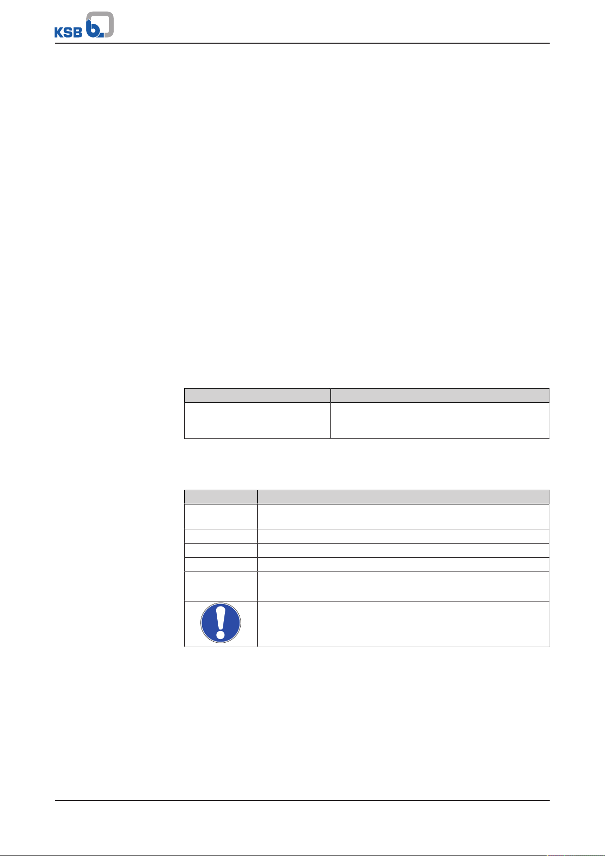
Table2: Symbols used in this manual
Symbol Description
✓ Conditions which need to be fulfilled before proceeding with the
step-by-step instructions
⊳ Safety instructions
⇨
⇨ Cross-references
1.
2.
Result of an action
Step-by-step instructions
Note
Recommendations and important information on how to handle
the product
6 of 60
KSBDeltaPrimo
Page 7
1 General
!
DANGER
!
WARNING
CAUTION
1.6 Key to safety symbols/markings
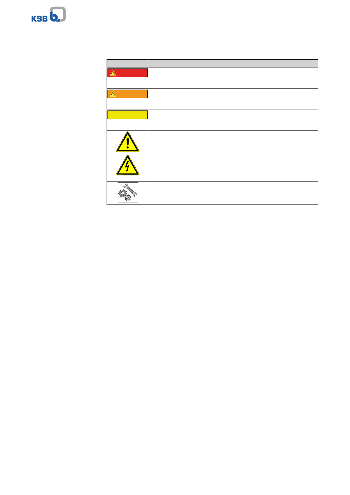
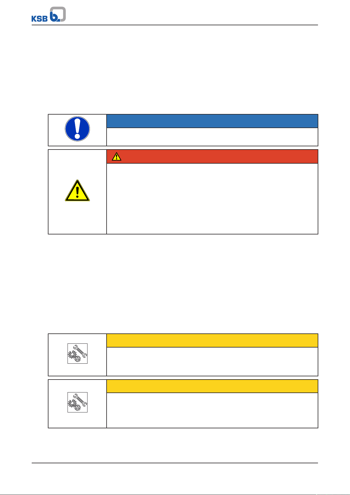
Table3: Definition of safety symbols/markings
Symbol Description
DANGER
This signal word indicates a high-risk hazard which, if not avoided,
will result in death or serious injury.
WARNING
This signal word indicates a medium-risk hazard which, if not
avoided, could result in death or serious injury.
CAUTION
This signal word indicates a hazard which, if not avoided, could
result in damage to the machine and its functions.
General hazard
In conjunction with one of the signal words this symbol indicates a
hazard which will or could result in death or serious injury.
Electrical hazard
In conjunction with one of the signal words this symbol indicates a
hazard involving electrical voltage and identifies information about
protection against electrical voltage.
Machine damage
In conjunction with the signal word CAUTION this symbol indicates
a hazard for the machine and its functions.
KSBDeltaPrimo
7 of 60
Page 8

2 Safety
!
DANGER
2 Safety
All the information contained in this section refers to hazardous situations.
In addition to the present general safety information the action-related safety
information given in the other sections must be observed.
2.1 General
This operating manual contains general installation, operating and maintenance
instructions that must be observed to ensure safe operation of the system and
prevent personal injury and damage to property.
The safety information in all sections of this manual must be complied with.
The operating manual must be read and understood by the responsible specialist
personnel/operators prior to installation and commissioning.
The contents of this operating manual must be available to the specialist personnel
at the site at all times.
Information attached directly to the product must always be complied with and kept
in a perfectly legible condition at all times. This applies to, for example:
▪ Arrow indicating the direction of rotation
▪ Markings for connections
▪ Name plate
The operator is responsible for ensuring compliance with all local regulations not
taken into account in this operating manual.
2.2 Intended use
▪ The pressure booster system must only be operated within the operating limits
described in the other applicable documents.
▪ Only operate pressure booster systems which are in perfect technical condition.
▪ Do not operate partially assembled pressure booster systems.
▪ The pressure booster system must only handle the fluids described in the product
literature of the respective design variant.
▪ Never operate the pressure booster system without the fluid to be handled.
▪ Observe the information on minimum flow rates specified in the product
literature (to prevent overheating, bearing damage, etc).
▪ Observe the maximum flow rates indicated in the data sheet or product
literature (to prevent overheating, cavitation damage, bearing damage, etc).
▪ Do not throttle the flow rate on the suction side of the pressure booster system
(to prevent cavitation damage).
▪ Consult the manufacturer about any other modes of operation not described in
the product literature.
2.2.1 Prevention of foreseeable misuse
▪ Never exceed the permissible application and operating limits specified in the
product literature regarding pressure, temperature, etc.
▪ Observe all safety information and instructions in this manual.
8 of 60
2.3 Personnel qualification and personnel training
All personnel involved must be fully qualified to install, operate, maintain and
inspect the machinery this manual refers to.
The responsibilities, competence and supervision of all personnel involved in
installation, operation, maintenance and inspection must be clearly defined by the
operator.
KSBDeltaPrimo
Page 9

2 Safety
Deficits in knowledge must be rectified by means of training and instruction
provided by sufficiently trained specialist personnel. If required, the operator can
commission the manufacturer/supplier to train the personnel.
Training on the pressure booster system must always be supervised by technical
specialist personnel.
2.4 Consequences and risks caused by non-compliance with this manual
▪ Non-compliance with these operating instructions will lead to forfeiture of
warranty cover and of any and all rights to claims for damages.
▪ Non-compliance can, for example, have the following consequences:
– Hazards to persons due to electrical, thermal, mechanical and chemical
effects and explosions
– Failure of important product functions
– Failure of prescribed maintenance and servicing practices
– Hazard to the environment due to leakage of hazardous substances
2.5 Safety awareness
In addition to the safety information contained in this manual and the intended use,
the following safety regulations shall be complied with:
▪ Accident prevention, health regulations and safety regulations
▪ Explosion protection regulations
▪ Safety regulations for handling hazardous substances
▪ Applicable standards, directives and laws
2.6 Safety information for the operator/user
▪ Fit protective equipment (e.g. contact guards) supplied by the operator for hot,
cold or moving parts, and check that the equipment functions properly.
▪ Do not remove any protective equipment (e.g. contact guards) during operation.
▪ Eliminate all electrical hazards. (In this respect refer to the applicable national
safety regulations and/or regulations issued by the local energy supply
companies.)
▪ If shutting down the pump does not increase potential risk, fit an emergency-
stop control device in the immediate vicinity of the pump (set) during pump set
installation.
2.7 Safety information for maintenance, inspection and installation
▪ Modifications or alterations of the pressure booster system are only permitted
with the manufacturer's prior consent.
▪ Use only original spare parts or parts authorised by the manufacturer. The use of
other parts can invalidate any liability of the manufacturer for resulting damage.
▪ The operator ensures that maintenance, inspection and installation is performed
by authorised, qualified specialist personnel who are thoroughly familiar with
the manual.
▪ Carry out work on the pressure booster system during standstill only.
▪ The pump casing must have cooled down to ambient temperature.
▪ Pump pressure must have been released and the pump must have been drained.
▪ When taking the pressure booster system out of service always adhere to the
procedure described in the manual.
▪ Decontaminate pressure booster systems which handle fluids posing a health
hazard.
KSBDeltaPrimo
9 of 60
Page 10

2 Safety
▪ As soon as the work has been completed, re-install and/or re-activate any safety-
relevant and protective devices. Before returning the product to service, observe
all instructions on commissioning.
▪ Make sure the pressure booster system cannot be accessed by unauthorised
persons (e.g. children).
▪ Prior to opening the device, pull the mains plug and wait for at least 10minutes.
2.8 Unauthorised modes of operation
Always observe the limits stated in the product literature.
The warranty relating to the operating reliability and safety of the pressure booster
system supplied is only valid if the equipment is used in accordance with its intended
use. (ðSection2.2,Page8)
10 of 60
KSBDeltaPrimo
Page 11

3 Software Changes
3 Software Changes
The software has been specially created for this product and thoroughly tested.
Making changes or additions to the software or parts of the software is prohibited.
This does not, however, apply to software updates supplied by KSB.
KSBDeltaPrimo
11 of 60
Page 12
4 Transport/Temporary Storage/Disposal
4 Transport/Temporary Storage/Disposal
4.1 Checking the condition upon delivery
1. On transfer of goods, check each packaging unit for damage.
2. In the event of in-transit damage, assess the exact damage, document it and
notify KSB or the supplying dealer and the insurer about the damage in writing
immediately.
4.2 Transport
NOTE
The pressure booster system is bolted to a pallet and wrapped in plastic film for
shipping and temporary storage. All connecting points are capped.
DANGER
Pressure booster system tipping over
Danger to life from falling pressure booster system!
▷ Never suspend the pressure booster system by its power cable.
▷ Do not lift the pressure booster system by its manifold.
▷ Observe the applicable local accident prevention regulations.
▷ Observe the information on weights, centre of gravity and fastening points.
▷ Use suitable and permitted transport equipment, e.g. crane, forklift or pallet
jack.
ü The pressure booster system has been checked for in-transit damage.
1. Make sure the transport equipment is suitable for safely carrying the indicated
load.
2. Transport the pressure booster system to the place of installation.
3. Attach the pressure booster system to the lifting tackle. Lift it off the pallet.
Dispose of the pallet.
4. Use suitable lifting equipment to lift the pressure booster system and carefully
place it down at the place of installation.
4.3 Storage/preservation
If commissioning is to take place some time after delivery, we recommend that the
following measures be taken when storing the pressure booster system:
CAUTION
Damage during storage due to frost, moisture, dirt, UV radiation or vermin
Corrosion/contamination of pressure booster system!
▷ Store the pressure booster system in a frost-proof room. Do not store outdoors.
CAUTION
Wet, contaminated or damaged openings and connections
Leakage or damage of the pressure booster system!
▷ Only open the openings of the pressure booster system at the time of
installation.
12 of 60
Store the pressure booster system in a dry, protected room where the atmospheric
humidity is as constant as possible.
KSBDeltaPrimo
Page 13

4 Transport/Temporary Storage/Disposal
4.4 Return to supplier
1. Drain the pressure booster system as per operating instructions.
2. Always flush and clean the pressure booster system, particularly if it has been
used for handling noxious, explosive, hot or other hazardous fluids.
3. If the pressure booster system has handled fluids whose residues could lead to
corrosion damage in the presence of atmospheric humidity or could ignite upon
contact with oxygen, the pressure booster system must also be neutralised and
treated with anhydrous inert gas to ensure drying.
4. Always complete and enclose a certificate of decontamination when returning
the pressure booster system. (ðSection13,Page55)
Always indicate any safety and decontamination measures taken.
NOTE
If required, a blank certificate of decontamination can be downloaded from the
following web site: www.ksb.com/certificate_of_decontamination
4.5 Disposal
WARNING
Fluids handled, consumables and supplies which are hot and/or pose a health
hazard
Hazard to persons and the environment!
▷ Collect and properly dispose of flushing fluid and any fluid residues.
▷ Wear safety clothing and a protective mask if required.
▷ Observe all legal regulations on the disposal of fluids posing a health hazard.
1. Dismantle the pressure booster system.
Collect greases and other lubricants during dismantling.
2. Separate and sort the pump materials, e.g. by:
- Metals
- Plastics
- Electronic waste
- Greases and other lubricants
3. Dispose of materials in accordance with local regulations or in another
controlled manner.
KSBDeltaPrimo
13 of 60
Page 14
5 Description
ID PN
Prod. IP
RDP PO
U Kalkovenweg 13
F Alphen a/d Rijn, NL
Imax www.ksb.com
KSB B. V.
Made in NL
KSB Delta Primo 3/1508
SVP
48278756
56.1A
50 Hz
3x400V
PT
01/2018 1234567-01
123456789
54
16
1
14
13
12
6
11
10
9
8
7
2
5
4
3
5 Description
5.1 General description
▪ Pressure booster system
5.2 Designation
Example: KSB Delta Primo 3/1508 SVP
Table4: Designation key
Code Description
KSB Delta Primo Type series
3 Number of pumps
15 Pump size
08 Number of pump stages
SVP Design
K Fixed speed pressure booster system
VP Pressure booster system with cabinet-mounted variable speed
SVP Pressure booster system with variable speed system and
system
KSB SuPremE motor
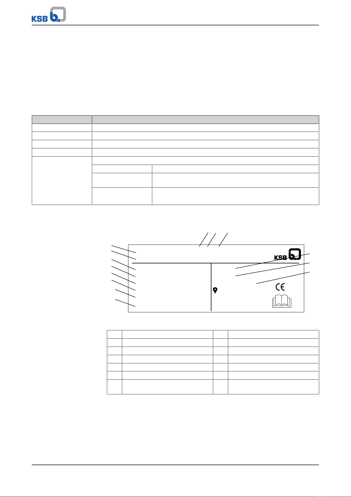
5.3 Name plate
Fig.1: Name plate (example)
1 Type series 8 Dry running protection
2 Design 9 Power supply voltage
3 Number of pumps 10 Power supply frequency
4 Size 11 Maximum current input
5 Number of pump stages 12 Max. operating pressure
6 Serial number 13 Enclosure
7 Month of production/ year of
production, consecutive number
14 Order number
14 of 60
KSBDeltaPrimo
Page 15

5 Description
5.4 Design details
Design
▪ Compact system mounted on a common base frame
▪ One or more vertical high-pressure pumps with variable speed system
▪ Hydraulic components made of stainless steel/ brass for high operating reliability
Multiple pump system:
▪ Check valve per pump
▪ Discharge-side gate valve per pump
▪ Suction-side gate valve per pump
KSB Delta Primo K:
▪ Power contactor per pump
KSB Delta Primo VP, SVP:
▪ One frequency inverter per pump
Installation
▪ Stationary dry installation
Drive
KSB Delta Primo K, VP:
▪ Electric motor
▪ Efficiency class IE3 to IEC60034-30
KSB Delta Primo SVP:
▪ Magnetless synchronous reluctance motor
▪ Efficiency class IE5 to IEC60034-30
▪ KSB SuPremE
Automation
▪ Control cabinet IP54
– Sheet steel housing: colour RAL7035
– BoosterControl Advanced
– Graphical display with operating panel
– Three LEDs signalling the operating status
– Lockable master switch (repair switch)
– Motor protection switch per pump
– Service interface for KSB ServiceTool
KSBDeltaPrimo
15 of 60
Page 16
5 Description
1
2
3
4
5
6
1
2
3
4
5
6
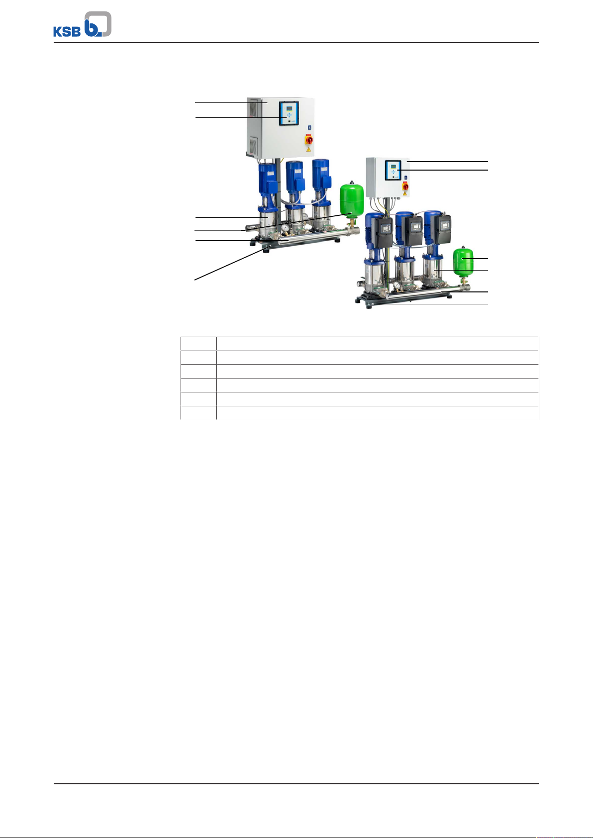
5.5 Configuration and function
Fig.2: KSB Delta Primo
1 Control cabinet
2 Control unit
3 Vertical high-pressure pumps
4 Membrane-type accumulator
5 Manifold
6 Baseplate
Design Fully automatic pressure booster system with two or three vertical high-pressure
pumps (3) for ensuring the required supply pressure
Function KSB Delta Primo K:
Either 2 or 3 pumps are controlled and monitored by a micro-processor control unit
(BoosterControl Advanced). The first pump is started up when the pressure falls
below the set start-up pressure. Additional pumps are sequenced in automatically in
line with actual demand. When demand decreases, the pumps are sequenced out
again as the stop pressure (start-up pressure+ deltap) is reached. The pump that has
been started up first will be stopped first. The pumps are automatically started up in
a different order for each new cycle. The actual pressure is measured by an analog
pressure measuring device (pressure transmitter). The function of this pressure
transmitter is monitored (live-zero).
This ensures equal distribution of pump operating hours.
If a duty pump fails, the next pump is started up immediately. A fault is output,
which can be reported via volt-free contacts (e.g. to the control station).
The operating status is displayed via LEDs.
▪ Green: system ready for operation
▪ Yellow: warning
▪ Red: alert
2 volt-free contacts on terminals are provided for reporting warnings and alerts.
KSB Delta Primo VP, SVP:
Either 1 or more pumps are controlled and monitored by a micro-processor control
unit (BoosterControl Advanced). Each pump is operated on a frequency inverter and
controlled by the control unit so as to ensure a constant discharge pressure of the
pressure booster system.
As the demand increases or decreases, peak load pumps are started and stopped
automatically. As soon as the demand increases again after one pump has been
stopped, another pump which has not been in operation before is started up. When
16 of 60
KSBDeltaPrimo
Page 17
5 Description
the last pump has been stopped and the demand increases again, the next pump in
line is started up on a frequency inverter. The stand-by pump is also included in the
alternating cycle.
The standard setting is for the pressure booster system to start automatically as a
function of pressure. As long as the pressure booster system is in operation, the
pumps are started and stopped as a function of demand (standard setting). In this
way it is ensured that the individual pumps operate only in line with actual demand.
If the demand drops towards 0, the pressure booster system slowly runs down to the
stop point.
The operating status is displayed via LEDs.
▪ Green: system ready for operation
▪ Yellow: warning
▪ Red: alert
2 volt-free contacts on terminals are provided for reporting warnings and alerts.
5.6 Noise characteristics
The pressure booster systems are available with different numbers of pumps and
different pump sizes.
Therefore, the expected total sound pressure level in dB(A) needs to be calculated.
1. Refer to the pumps' operating manual for the noise characteristics of the
individual pumps.
2. Calculate the expected total sound pressure level.
Table5: Calculating the expected total sound pressure level
Number of pumps Expected total sound pressure level
Single pump See pump operating manual
2 pumps +3dB(A)
3 pumps +4,5dB(A)
Total dB(A)
Table6: Example of calculating the expected total sound pressure level
Number of pumps Expected total sound pressure level
Single pump 48dB(A)
2 pumps +3dB(A)
Total 51dB(A)
The expected total sound pressure level of 51dB(A) for this configuration may
develop when both pumps are running under full-load conditions.
5.7 Scope of supply
Depending on the model, the following items are included in the scope of supply:
▪ 2 or 3 vertical high-pressure centrifugal pumps with oval flange
▪ Powder-coated / epoxy resin-coated steel baseplate
▪ Integrated check valve per pump
▪ Discharge-side gate valve per pump
▪ Suction-side gate valve per pump
▪ Suction-side manifold and discharge-side manifold made of stainless steel
▪ Pressure transmitter on the discharge side
▪ Pressure gauge
▪ Dry running protection switch on the inlet pressure side
▪ Membrane-type accumulator on the discharge side, approved for drinking water
▪ Control cabinet IP54
– Sheet steel housing: colour RAL7035
KSBDeltaPrimo
17 of 60
Page 18
5 Description
1
2
– Parameterisable BoosterControl Advanced control unit
– Graphical display with operating panel
– Three LEDs signalling the operating status
– Lockable master switch (repair switch)
– Motor protection switch per pump
– One frequency inverter per pump
– Service interface for KSB ServiceTool
5.8 Dimensions and weights
For dimensions and weights refer to the outline drawings of the pressure booster
system.
5.9 Terminal wiring diagram
For the terminal assignment refer to the circuit diagram.
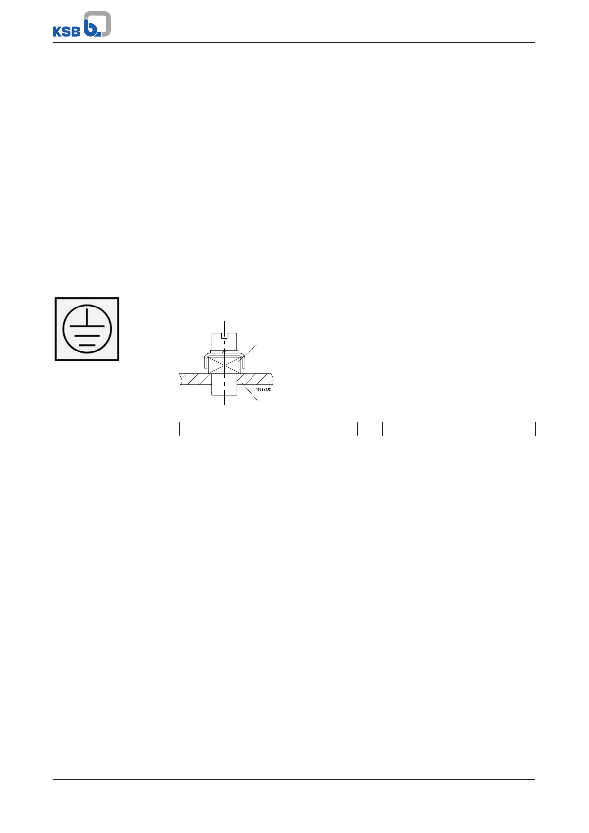
5.10 Potential equalisation
A terminal marked with the earth symbol is provided on the baseplate for connecting
a PE conductor.
Fig.3: Earth symbol
Fig.4: PE terminal
1 Earthing terminal 2 Baseplate
18 of 60
KSBDeltaPrimo
Page 19

6 Installation at Site
6 Installation at Site
6.1 Installation
Install pressure booster systems either in the technical equipment room or in a wellventilated, frost-free, lockable room used for no other purpose. No harmful gases are
allowed to enter the installation room. An adequately sized drain (leading to a sewer
or equivalent) must be provided.
The pressure booster system is designed for a maximum ambient temperature of 0°C
to +40°C1) at a relative humidity of 50%.
NOTE
Do not install pressure booster systems next to sleeping or living quarters.
The anti-vibration mounting of the pressure booster system provides adequate
insulation against solid-borne noise. If expansion joints (see accessories) are used for
damping vibrations, their fatigue strength (endurance limit) must be given due
consideration. Expansion joints must be easily replaceable.
6.2 Checks to be carried out prior to installation
Place of installation
WARNING
Installation on mounting surfaces which are unsecured and cannot support the
load
Personal injury and damage to property!
▷ Use a concrete of compressive strength class C12/15 which meets the
requirements of exposure class X0 to EN206-1.
▷ The mounting surface must have set and must be completely horizontal and
even.
▷ Observe the weights indicated.
NOTE
The anti-vibration mounts of the pressure booster system provide adequate
insulation against solid-borne noise.
1. Check the structural requirements.
All structural work required must have been prepared in accordance with the
dimensions stated in the outline drawing.
6.3 Installing the pressure booster system
1) KSB Delta Primo VP: +30°C
WARNING
Top-heavy pressure booster system
Risk of personal injury by pressure booster system tipping over!
▷ Pressure booster systems awaiting final installation must be secured against
tipping over.
▷ Firmly anchor the pressure booster system.
Remove all packaging before installing the pressure booster system. Connect the
pressure booster system's inlet line and discharge line to the corresponding site
distribution lines.
KSBDeltaPrimo
19 of 60
Page 20

6 Installation at Site
NOTE
In order to avoid transmission of piping forces onto the pressure booster system
and transmission of solid-borne noise, we recommend installing length-limited
expansion joints.
Allow sufficient space for maintenance and repair work.
ü All structural work required has been checked.
ü The dimensions of the concrete foundation are correct, and the concrete has set
firmly.
1. Mark out the anchoring holes on the floor as shown in the outline drawing.
2. Drill the holes (max. diameter: 12mm).
3. Insert plug fixings of appropriate size.
4. Set the pressure booster system down in its correct installation position.
5. Use suitable bolts to firmly anchor the pressure booster system.
6.4 Connecting the piping
Make sure that piping is installed without transmitting any stresses or strains. The use
of length-limited expansion joints (KSB accessory) is advisable.
6.4.1 Fitting an expansion joint
DANGER
Sparks and radiant heat
Fire hazard!
▷ Take suitable precautions to protect the expansion joint if any welding work is
carried out nearby.
CAUTION
Leaking expansion joint
Flooding of installation room!
▷ Regularly check for cracks or blisters, exposed fabric or other defects.
ü The expansion joint has a length limiter with solid-borne sound insulation so as
to be able to absorb reaction forces.
1. Install the expansion joint in the piping free of twist or distortion. Never use the
expansion joint to compensate for misalignment or mismatch of the piping.
2. Tighten the bolts evenly and crosswise during assembly. The ends of the bolts
must not protrude from the flange.
3. Do not apply paint to the expansion joint. Protect it from any contact with oil.
4. The position of the expansion joint within the pressure booster system must
allow easy access and inspection and it must, therefore, not be insulated along
with the piping.
5. Expansion joints are subject to wear.
20 of 60
6.4.2 Installing a pressure reducer
NOTE
A pipe length of approximately 600 mm must be provided on the inlet side to
accommodate a pressure reducer, if necessary.
KSBDeltaPrimo
Page 21

6 Installation at Site
NOTE
A pressure reducer must be installed
- if the inlet pressure fluctuation is too high for the pressure booster system to
operate as intended or
- if the total pressure (inlet pressure plus shut-off head) of the pressure booster
system exceeds the design pressure.
The maximum pump discharge pressure at zero flow point is reached in manual
mode.
A minimum pressure gradient of 5 metres is required for the pressure reducer to
fulfill its function. The pressure downstream of the pressure reducer (downstream
pressure) is the basic parameter for determining the pump head.
For example:
The inlet pressure fluctuates between 4 and 8 bar. A pressure reducer is needed
upstream of the pressure booster system on the inlet side.
Min. inlet pressure (p
Min. pressure gradient=0.5bar
Downstream pressure=3.5bar.
6.5 Connection to power supply
)=4bar
inl
DANGER
Electrical connection work by unqualified personnel
Danger of death from electric shock!
▷ Always have the electrical connections installed by a trained and qualified
electrician.
▷ Observe regulations IEC60364.
WARNING
Incorrect connection to the mains
Damage to the mains network, short circuit!
▷ Observe the technical specifications of the local energy supply companies.
NOTE
A motor protection device is recommended.
NOTE
If a residual current device is installed, observe the operating manual for the
frequency inverter.
The circuit diagrams for the pressure booster system are included in the control
cabinet, where they must remain when not in use.
The product literature of the switchgear and controlgear assembly supplied with the
pressure booster system includes a list of the electrical components installed. When
ordering spare parts for electrical components, please always indicate the circuit
diagram number.
6.5.1 Sizing the power cable
The cross-section of the power cable must be sized for the total rated power
requirement.
KSBDeltaPrimo
21 of 60
Page 22

6 Installation at Site
6.5.2 Connecting the pressure booster system
Connect the pressure booster system to the power supply as per the enclosed circuit
diagram.
Observe the data on the name plate.
6.5.3 Volt-free contacts
Volt-free contacts are provided for the following messages:
▪ Warning
▪ Alert
The terminals are marked in the circuit diagram and in the switchgear and
controlgear assembly.
22 of 60
KSBDeltaPrimo
Page 23

7 Commissioning/Start-up/Shutdown
7 Commissioning/Start-up/Shutdown
7.1 Commissioning/Start-up
7.1.1 Prerequisites for commissioning/start-up
Before commissioning/start-up of the pressure booster system make sure that the
following requirements are met:
▪ The pressure booster system has been properly connected to the electric power
supply and is equipped with all protection devices.
▪ All relevant regulations applicable in the country of use are complied with.
NOTE
The competent authorities must be informed in due time prior to commissioning/
test running the system.
7.1.2 Dry running protection
Pressure booster systems are fitted with a pressure switch as dry running protection
device.
A float switch whose volt-free contact closes the circuit in upper float position can be
connected to the control system as dry running protection. Follow the float switch
manufacturer's instructions on how to set the float switch levels.
Table7: Levels for dry running protection
Dry running protection device Stop pressure Start-up pressure
[bar] [bar]
Pressure switch 0,2 1,1
7.1.3 Commissioning/start-up of pressure booster system
NOTE
The pressure booster systems undergo hydraulic testing with water at the factory
and are drained carefully before shipment. However, for technical reasons the
presence of some residual water is unavoidable.
The hydraulic connections are closed in as-supplied condition. They must only be
opened immediately before installation.
Refer to EN806 before commissioning/starting up the pressure booster system.
After an extended pre-installation period, in particular, flushing or even
professional disinfection is recommended. For extensive or branched piping systems
the pressure booster system should preferably be flushed either before installation,
or flushing should be restricted to a limited area.
CAUTION
Foreign matter in the piping
Damage to the pumps/pressure booster system!
▷ Before commissioning/starting (or even test running) the pressure booster
system, make sure that there is no foreign matter in the pressure booster
system or piping.
NOTE
Commissioning of the pressure booster system - even test running - shall only be
carried out in full compliance with all pertinent VDE (German Association of
Electrical Engineers) regulations.
KSBDeltaPrimo
23 of 60
Page 24

7 Commissioning/Start-up/Shutdown
CAUTION
Operation without the fluid to be handled
Damage to the pump!
▷ Prime the pressure booster system with the fluid to be handled.
ü The pipe unions between the pump and the piping have been re-tightened.
ü The flange bolting has been checked for firm seating.
ü The cooling air inlet and outlet openings on the motor are unobstructed.
ü All shut-off valves of the pressure booster system are open.
ü The pre-charge pressure of the membrane-type accumulator has been checked.
(ðSection9.2.3,Page42)
1. Set the master switch to "0"; unlock all motor protection switches (if
applicable).
2. Provide connection to power supply.
3. Open/loosen the vent plugs on the pumps (refer to the pump's installation/
operating manual).
4. Slowly open the inlet-side shut-off element and prime the pressure booster
system until the fluid to be handled escapes through all vent holes.
5. Insert and slightly tighten the pump vent plugs.
6. Switch on all motor protection switches.
7. Switch on the master switch.
8. Start one pump after the other in manual mode, checking the direction of
rotation. The direction of rotation must match the rotation arrow on the motor.
If the pump runs in the wrong direction of rotation, interchange two phases at
the motor terminal strip.
9. Open the discharge-side shut-off element.
10. Then re-tighten the vent plug firmly.
11. Check that the pumps are running smoothly.
12. Close the discharge-side shut-off element, causing all pumps to stop.
NOTE
Minor leakage of the mechanical seals during commissioning is normal and will
cease after a short period of operation.
7.2 Switching on the pressure booster system
Switch on the master switch to energise the pressure booster system. The green LED
on the control panel lights up, indicating the system's readiness for operation.
CAUTION
Pressure booster system not set to requirements
Damage to the pump/pressure booster system!
▷ Adjust the settings of the pressure booster system to the pressure conditions at
the site.
▷ Set the functions as required.
24 of 60
KSBDeltaPrimo
Page 25

7 Commissioning/Start-up/Shutdown
7.3 Checklist for commissioning/start-up
Table8: Checklist
Actions Done
1 Read the operating manual.
2 Verify the power supply against the name plate data.
3 Check the earthing system (taking measurements).
4 Check the mechanical connection to the water mains.
Re-tighten the flange bolting and pipe unions.
5 Prime and vent the pressure booster system from the inlet side.
6 Check the inlet pressure.
7 Check whether all cables are still firmly connected to the terminals inside the control unit.
8 Compare the set values of the motor protection switches with the name plate data; if
required, readjust.
9 Briefly start up one pump after the other in manual mode and compare the direction of
rotation at the fanwheel with the arrow indicating the direction of rotation.
10 Check the start and stop pressure; re-adjust if necessary.
11 Check that the dry running protection equipment is working properly.
12 Vent the pumps for a second time after they have been running for 5 to 10minutes.
13 Check the pre-charge pressure of the (membrane-type) accumulator.
14 Record all system conditions that do not correspond to our specifications or to the purchase
order in the commissioning report (i.e. no dry running protection or inlet pressure + max.
pressure of pressure booster system higher than 16bar).
15 Complete the commissioning report together with the operator/user and instruct the operator/
user as to the function of the unit.
7.4 Shutdown
NOTE
As long as the pressure booster system is out of operation, water is supplied directly
at p
through the pressure booster system.
inl
Set the master switch to "0".
NOTE
Drain the pressure booster system for prolonged shutdown.
KSBDeltaPrimo
25 of 60
Page 26

8 Operating the Pressure Booster System
1
2
3
4
5
8 Operating the Pressure Booster System
8.1 KSB Delta Primo K, VP, SVP
CAUTION
Incorrect operation
Water supply is not assured!
▷ Make sure to comply with all local regulations, particularly the EC Machinery
Directive and the EC Directive on Low-Voltage Equipment.
The pressure booster system is factory-set to the start-up pressure and stop pressure
indicated on the name plate.
The settings can be modified via the control panel if necessary.
NOTE
The factory settings are permanently stored in the control unit. Should an incorrect
setting result in pressure booster system failure, the factory settings can be
restored. (ðSection8.1.8.2,Page36)
NOTE
The settings made at the site can be saved and loaded when required.
(ðSection8.1.8.1,Page36) (ðSection8.1.8.2,Page36)
8.1.1 Control panel
The control panel comprises a back-lit display, LEDs, function and navigation keys,
and an access point for the service interface.
The display shows important information for operating the pressure booster system.
Plain-text data can be accessed and parameters can be set.
26 of 60
Fig.5: BoosterControl Advanced control panel
KSBDeltaPrimo
Page 27

8 Operating the Pressure Booster System
3-5
C
Pressure
Setpoint
Bandwidth
Accumulator pressure
Max. setpoint
22-05 13:40
1 Display 2 "Traffic light" LEDs
3 Function keys 4 Navigation keys
5 Service interface
8.1.1.1 Display
The six-row display contains the following information:
Fig.6: Control unit: Display elements
Display element Description
Parameter No./Pump Shows the number of the parameter or pump
selected
Current selection Shows the current parameter in plain text
Parameter information List of selectable parameters/parameter
information
Access level Shows the current access level:
Blank = Standard
(limited access to parameters)
C = Customer, access to main parameters
S = Service
F = Factory
Date, time Shows the set date and time
Example: Setpoint adaptation at "Customer" access level:
Fig.7: Display: Setpoint adaptation
The number of the current menu or parameter is always displayed at the top left of
the screen. This number indicates the path through the menu levels and thus enables
the user to quickly locate parameters. See "Displaying and changing parameters".
(ðSection8.1.4,Page30)
8.1.1.2 LEDs
The "traffic light" LEDs provide information about the pump system's operating
status.
KSBDeltaPrimo
27 of 60
Page 28

8 Operating the Pressure Booster System
Esc
OK
?
Table9: LED description
LED Description
Red: One or more than one alert is active
Amber: One or more than one warning is active
Green: Trouble-free operation
8.1.1.3 Function keys
You can use the menu keys to access the elements at the first menu level directly.
Table10: Assignment of menu keys
Key Menu
Operation
Diagnosis
Settings
Information
8.1.1.4 Navigation keys
For navigating through the menus and confirming settings:
Table11: Control unit: Navigation keys
Key Description
Direction keys:
▪ Move up/down in the menu options
▪ Increase/decrease a numerical value
▪ Scroll up or down
Escape key:
▪ Cancel an entry without saving it.
▪ Move up one menu level.
OK key:
▪ On the start display: Open the quick menu.
▪ Confirm settings.
▪ Confirm a menu selection.
▪ When entering numbers: Go to the next digit.
Help key:
▪ Displays a help text for each selected menu option.
8.1.1.5 Service interface
The service interface allows a PC/Notebook to be connected via a special cable (USB RS232).
The pressure booster system can be parameterised by using the Service-Tool
software.
The control unit can also be updated via this interface.
28 of 60
8.1.2 Menu structure
Main menu: KSB logo/actual value display
KSBDeltaPrimo
Page 29

8 Operating the Pressure Booster System
Main menu Key Sub-menu Information displayed
➡ Operation ➡ General System pressure
System load %
RDP switch present/not present
Inlet pressure
Level content %
Level height m
Ambient temp.
Digital inputs
➡ Pumps Operating mode of pumps
Display pump load
Display thermal protection
➡ Time and statistics Operating hours
Service interval
Current min. runtime
➡ Diagnosis ➡ General Display messages
Show history
Acknowledge faults
Clear history
➡ Settings ➡ Control panel Basic settings
CAN configuration
Service interface
Logo
➡ Control unit Login
Service
➡ System configuration Number of pumps
Configuration suction side
Configuration operating mode
➡ System settings Suction side
Discharge side
Configuration of frequency inverter
➡ Pressure configuration Configuration setpoint and dry running protection
➡ Timer settings Operation check run/alternative setpoint
➡ Time/date
➡ Program outputs
➡ Messages
➡ Main menu
➡ Information ➡ Control module Serial number
Material number
Firmware
Parameter set
Hardware version
8.1.3 Access levels
Various access levels have been defined to prevent unintentional or unauthorised
access to the pressure booster system parameters.
"Standard" level Unless users log on to one of the other access levels, they will only have limited access
to parameters.
"Customer" level Access level for expert users.
This level enables access to all the parameters required for commissioning. You must
enter the password under (3-2-1-1) Login to gain access.
"C" is displayed.
If password protection is deactivated via parameter 3-2-1-2, this access level becomes
the "Standard" access level.
The password is "7353".
"Service" level Access level for service personnel.
You must enter the password under (3-2-1-1) Login to gain access.
"S" is displayed.
KSBDeltaPrimo
29 of 60
Page 30

8 Operating the Pressure Booster System
"Factory" level Access level for the manufacturer only.
"F" is displayed.
NOTE
If no keys are pressed for ten minutes, the system will automatically return to the
"Standard" access level.
8.1.4 Displaying and changing parameters
The parameter numbers contain the navigation path, which helps you find a
particular parameter quickly and easily.
The first digit of the parameter number indicates the first menu level, which is called
up directly via the four function keys.
Table12: Function keys
Operation
Diagnosis
Settings
Information
Subsequent steps are carried out via the navigation keys.
Example: Parameter 3-5-1 Setpoint
First, enter the customer password. (ðSection8.1.3,Page29)
Then change the setpoint as follows:
First digit of parameter number: 3-5-1
Press the third function key for Settings.
3-1 appears on the top left of the screen.
Second digit of parameter number: 3-5-1
Change the display 3-1 (top left) to 3-5 by pressing the navigation
keys.
To confirm the selection, press OK. 3-5-1 appears on the top left of
the screen. You have reached the required parameter.
To change this parameter, press OK again.
Numbers can then be entered digit by digit from left to right.
Increase value.
Reduce value.
30 of 60
The bar above the entry displays the value currently being entered in relation to the
value range.
Confirm the selected value by pressing OK. The cursor moves to the
next position (second position from the left).
Make the settings for the subsequent positions as described above and then
KSBDeltaPrimo
Page 31

8 Operating the Pressure Booster System
press OK to save the new parameter value.
Press ESC several times to return to the main display.
The new setpoint is now active.
8.1.5 Displaying messages
All monitoring and protective functions trigger warnings or alerts. These are
signalled by the yellow or red LED and connected to the relay outputs.
▪ All current messages can be displayed in the Diagnosis menu under 2-1-1 and
acknowledged individually if the cause of the fault has gone.
▪ The history of messages can be accessed in the Diagnosis menu under 2-1-2. It
indicates the start and end of a fault.
▪ The list of fault messages can be acknowledged in the Diagnosis menu under
2-1-3.
▪ The history of messages can be deleted in the Diagnosis menu under 2-1-4. For
this step, you have to login at the "Service" level.
When the pressure booster system is reset (by switching the pressure booster system
off and on with the master switch), all alerts are acknowledged automatically.
Acknowledging alerts may cause the system to re-start.
8.1.6 Description of parameters
8.1.6.1 Parameter group 1 "Operation"
Access via "Operation" key
Parameters starting with the digit "1" indicate current operating conditions.
Exception: Parameter 1-2-1, which can be used to start and stop individual pumps in
Fig.8: Operation key
Parameter Description
1-1-1 System pressure
1-1-2 System load 0 to 300%, depending on the number of pumps in operation.
1-1-3 Indicates whether a dry running protection device is connected or not.
1-1-7 Ambient temperature, if "Temperature" function has been selected under 3-3-4, WSD.
1-1-8 For Service only: Status of digital inputs.
1-1-10 Power down speed. If the rotational speed of the variable-speed pump drops below this speed (set
under 3-11-3), the pump will stop. Only active if energy-saving mode has been activated under 3-11-1.
1-2-1 Operating mode. After the pump has been selected (by entering the pump number), it can be run
either in automatic mode, in manual mode (for 10 seconds), or switched off. If the pump was
switched off via this parameter, the same parameter will have to be used to return the pump to
automatic mode again.
This pump cannot be switched on again by means of a voltage reset!
If a pump has been operated in manual mode via this parameter, it will automatically return to its
previous operating mode after 10seconds.
1-2-2 Pump load indicates the load per pump.
1-2-3 For Service only: Thermal fail. flags.
1-2-4 Running hours pump.
1-2-5 For Service only: Number of pumpstarts and failures.
manual mode.
KSBDeltaPrimo
31 of 60
Page 32

8 Operating the Pressure Booster System
8.1.6.2 Parameter group 2 "Diagnosis"
Access via "Diagnosis" key
Parameters starting with the digit "2" are used for fault diagnosis.
Fig.9: Diagnosis key
Parameter Description
2-1-1 Displaying messages. Current faults are displayed.
A ring next to the fault means that the fault has gone but has not been acknowledged yet.
A ring filled with a dot means that the fault is still active but cannot be acknowledged.
2-1-2 Displaying history. The last six faults are displayed.
A ring next to the fault means that the fault has gone but has not been acknowledged yet.
A ring filled with a dot means that the fault is still active but cannot be acknowledged.
2-1-3 Acknowledging faults.
2-1-4 For Service only: Deleting the fault history.
8.1.6.3 Parameter group 3 "Settings"
Access via "Settings" key
This key is used to change parameters which are required to adjust the pressure
booster system to site conditions if the data specified in the purchase order no longer
Fig.10: Settings key
Parameter Description
3-1 Control panel
3-1-1 Basic settings of the control panel. Parameters 3-1-1-1 and 3-1-1-2 can be changed at the Standard
access level.
3-1-1-1 Language settings
3-1-1-2 Backlight settings for the display: 3-1-1-2-1 serves to select the backlighting modes "Always ON“ or
"Timer-based". If "Timer-based" is selected, the backlight time can be set from 0 to 999seconds
under 3-1-1-2-2.
3-1-1-3 Service only: Displayed units for pressure (3-1-1-3-1), fill level (3-1-1-3-2) and temperature (3-1-1-3-3).
3-1-2 Service only: Fieldbus type and address.
3-1-3 Factory only: Service interface settings.
3-1-4 Factory only: Logo on start screen.
3-2 Control unit
3-2-1 Login. The various login levels can be selected under 3-2-1-1. The password for the "Customer" level is
7353. The password prompt for this access level can be deactivated under 3-2-1-2.
3-2-2 Service. 3-2-2 provides access to the parameters required for saving and restoring settings.
3-2-2-1 "Customer" level. Resetting the pressure booster system to the factory settings it was delivered with.
3-2-2-2 "Service" level. Resetting the service interval.
3-2-2-3 "Customer" level. Resetting to the settings made at the site and saved under 3-2-2-4.
3-2-2-4 "Customer" level. Saving the settings made at the site.
3-2-2-5 "Factory" level. Saving the factory settings the pressure booster system is delivered with.
3-2-2-6 "Factory" level. Resetting to default settings.
3-3 System configuration
All parameters can be changed at "Service" level.
3-3-1 Number of pumps in the system.
3-3-2 The "inlet" configuration defines the type of dry running protection used (by pressure switch,
pressure sensor or flow monitoring), or whether the individual inlet tank levels are processed and
whether inflow into the tank is controlled by means of a proportional valve or gate valve (on/off
valve).
3-3-3 "Discharge" configuration. Defines the control method (cascade operation, frequency inverter, jockey
pumps).
applies or if accessories or supplementary equipment have been retrofitted.
32 of 60
KSBDeltaPrimo
Page 33

8 Operating the Pressure Booster System
Parameter Description
3-3-4 WSD. Presently, only the ambient temperature can be analysed. If "Temperature" has been selected,
a Pt1000 sensor can be connected and the temperature measured can be displayed. If the
temperature exceeds the value entered under 3-4-4-3, a warning is output.
3-4 System settings
All parameters can be changed at "Service" level.
3-4-1 Inlet
3-4-1-1 Sensor press. 4 mA. Lower sensor limit, factory setting: 0bar.
3-4-1-2 Sensor press. 20mA. Upper sensor limit. Factory setting: 10bar.
3-4-1-3 Automatic RDP reset. Control unit response when lack of water signal has gone. Factory setting:
automatic reset.
3-4-1-4 Inlet tank configuration if inlet tank has been selected under 3-3-2.
3-4-1-4-1 0% level. Input of inlet tank level in cm or m (depending on setting made under 3-1-1-3-2) at 0% of
sensor signal.
3-4-1-4-2 100% level. Input of inlet tank level in cm or m (depending on setting made under 3-1-1-3-2) at
100% of sensor signal.
3-4-1-4-3 Sensor level. Sensor distance from tank floor.
3-4-1-4-4 Low level shut down. At this level the pressure booster system stops owing to lack of water.
3-4-1-4-5 Low level reset. At this level the pressure booster system starts again.
3-4-1-4-6 Critical water level. Level at which a warning is output: tank is almost empty.
3-4-1-4-7 High water level. Level at which a warning is output: high-water level is reached.
3-4-1-4-8 Threshold
3-4-1-4-8-1 Threshold1: ON
3-4-1-4-8-2 Threshold1: OFF
3-4-1-4-8-3 Threshold2: ON
3-4-1-4-8-4 Threshold2: OFF
3-4-1-4-9 Supply valve ON/OFF. These parameters define the levels at which the supply valve is opened and
closed, respectively. Level 1A is an alternative level which is activated under 3-7-9 and 3-7-10.
3-4-1-4-9-1 Level 1 open. Level at which the gate valve is to open.
3-4-1-4-9-2 Level 1 closed. Level at which the gate valve is to close.
3-4-1-4-9-3 Level 1A open. Level at which the gate valve is to open.
3-4-1-4-9-4 Level 1A closed. Level at which the gate valve is to close.
3-4-1-4-10 Supply valve prop.
3-4-1-4-10-1 Level setpoint 1. This parameter defines the level at which the proportional valve is fully open.
3-4-1-4-10-2 Level setpoint1A. This parameter defines the alternative level at which the proportional valve is fully
open. The alternative level is activated under 3-7-9 and 3-7-10.
3-4-1-4-10-3 Hysteresis
3-4-1-4-10-4 Sample time
3-4-2 Discharge side
3-4-2-1 Sensor press. 4 mA. Lower sensor limit, factory setting: 0bar.
3-4-2-2 Sensor press. 20mA. Upper sensor limit. Factory setting: 16bar.
3-4-2-3 Pumps ON sensor fail. This parameter defines the control unit response if the sensor current drops
below 4mA. A number between 0 and 6 is input. 0means that all pumps are stopped, 1means that
one pump is running, 6means that six pumps are running.
3-4-2-4 Max power. This parameter defines the maximum number of pumps allowed to run at the same time.
Input is in number of pumps x 100%.
3-4-3 Variable freq. drive.
3-4-3-1 Communication. Configuration of communication protocol used by control unit and frequency
inverter.
3-4-3-2 Proportional const. Proportional amplification factor of controller. The higher the value, the higher
the amplification.
3-4-3-3 Integral time. Integration time of controller. The higher the value, the faster the controller.
3-4-3-4 Differential const. Not used in pressure boosting applications.
KSBDeltaPrimo
33 of 60
Page 34

8 Operating the Pressure Booster System
Parameter Description
3-4-3-5 No-flow detection. Parameters determining the pressure booster system's stopping behaviour at zero
flow.
3-4-3-5-1 No-flow bandwidth. Permissible deviation of actual value from setpoint (settable from 2to18%)
interpreted as constant pressure at zero flow by the control unit.
3-4-3-5-2 No-flow time. Period (settable from 4to20s) during which the deviation set under 3-4-3-5-1 must be
valid for the control unit to identify zero flow.
3-4-3-5-3 No-flow step. Value must not be changed for pressure booster systems!
3-4-4 WSD settings. Only the temperature monitoring function is supported at the moment.
3-4-4-3 Average room temp. A warning is output if this temperature is exceeded.
3-5 Pressure
3-5-1 "Customer" level. Setpoint. Pressure at which the pumps start.
3-5-3 "Customer" level. Bandwidth. Value in bar (standard: 0.05bar) of permissible deviation of actual value
from setpoint.
3-5-4 "Customer" level. Accumulation press. Value added to the actual value before the last pump is
stopped.
3-5-5 "Service" level. Max. setpoint
3-5-6 "Service" level. Hmax. Maximum pump head at zero flow.
3-5-8 "Service" level. Average inlet press. This parameter indicates the inlet pressure of the system if a
pressure switch is used as dry running protection device.
3-5-9 "Customer" level. Adapt. setpoint. Activated under 3-7-8, Adapt. setpoint.
3-5-10 Delta p. This parameter defines by how many bar the setpoint is increased or decreased per running
pump.
For difficult site conditions only.
3-5-11 "Customer" level. High pressure alarm. This parameter defines the maximum pressure at which a
warning is to be output.
3-5-12 "Customer" level. High pressure action. This parameter defines the control unit's response when the
pressure set under 3-5-11 is reached. Selection options: "Stop pumps" or "Message only".
3-5-13 "Customer" level. Low pressure alarm. This parameter defines the minimum pressure at which a
warning is to be output.
3-5-14 "Service" level. Low pressure action. This parameter defines the control unit's response when the
pressure set under 3-5-13 is reached. Selection options: "Stop pumps" or "Message only".
3-5-15 "Service" level. Shut down RDP. Can only be selected if a pressure sensor has been selected for dry
running protection. This parameter defines the pressure at which lack of water is to be signalled.
3-5-16 "Service" level. Reset RDP. Can only be selected if a pressure sensor has been selected for dry running
protection. This parameter defines the pressure at which the lack of water has gone.
3-5-17 "Service" level. Press. Flow Control. Can only be selected if flow monitoring has been selected for dry
running protection. Lack of water is detected when the flow sensor detects zero flow and the
pressure on the discharge side falls below the setpoint minus the value entered here.
3-6 Timer settings
All parameters can be changed at "Service" level.
3-6-1 Opt. pump starts/h. Permissible pump starts per hour.
3-6-2 Min. run time. Minimum run time of the pump, even if the period between the start and stop
command is shorter.
3-6-3 Min. run time corr. Value added to the minimum run time if the number of pump starts is exceeded.
3-6-4 Max. run time. Period after which the pumps will be changed over in any case.
3-6-5 Start delay. Time between the start command and the actual pump start.
3-6-6 Stop delay. Time between the stop command and the actual pump stop.
3-6-8 RDP delay. Time between lack-of-water signal and pump stop.
3-6-9 High/low alarm delay. Time between the occurrence of a fault and the associated warning/alert.
3-7 Time/Date
All parameters except 3-7-7 and 3-7-11 can be changed at "Customer" level.
3-7-1 Date
3-7-2 Time
34 of 60
KSBDeltaPrimo
Page 35

8 Operating the Pressure Booster System
Parameter Description
3-7-3 Check run mode. Set according to requirements: System does not perform check run (set to OFF),
performs check run at given interval (set to "Interval-based"), every day at the same time (Time of
day based) or at a given time on a given day of week (Time of week based).
3-7-4 Check run interval. Can only be selected if "Interval-based" has been selected under 3-7-3. Enter the
interval in seconds.
3-7-5 (Daily) Check run at. Can only be selected if "Time of day based" has been selected under 3-7-3. Enter
hour and minute.
3-7-6 (Weekly) Check run at. Can only be selected if "Time of week based" has been selected under 3-7-3.
Enter hour, minute and weekday.
3-7-7 Check run duration. Duration of check run of each pump.
3-7-8 Clock adapt setp.
3-7-8-1 Adaptation mode. Set according to requirements: no alternative setpoint (set to OFF), every day at
the same time ("Adapt ON/OFF ev. day") or at a given time on a given day of week ("Adapt. ON/OFF
per day").
3-7-8-2 Change ON/OFF times. Can only be selected if "Adapt ON/OFF ev. day" has been selected under
3-7-8-1. Enter hour and minute for activating and deactivating the alternative setpoint.
3-7-8-3 Select day of week. Can only be selected if "Adapt ON/OFF per day" has been selected under 3-7-8-1.
Enter the weekday.
3-7-8-4 Change ON/OFF times. Can only be selected if "Adapt ON/OFF per day" has been selected under
3-7-8-1. Enter hour and minute for activating and deactivating the alternative setpoint.
3-7-9 Date adapt level ON. Month from which the alternative level specified under 3-4-1-4, Level
configuration, is to be activated.
3-7-10 Date adapt level OFF. Month from which the alternative level specified under 3-4-1-4, Level
configuration, is to be deactivated.
3-7-11 Maintenance interval. Enter the number of operating hours after which maintenance is to be
performed.
3-10 Main menu
"Customer" level. Set the information to be displayed in the main menu.
3-11 Energy Saving Mode
All parameters can be changed at "Service" level.
3-11-1 Energy Saving Mode ON/OFF. This parameter serves to activate/deactivate the energy-saving mode.
3-11-2 Direct Off. This parameter defines whether, upon reaching the "power down speed", the pressure
booster system stops after the delay set under 3-11-4 or flow detection is started.
3-11-3 Power down speed. Enter the pump load at which the last pump is to stop.
3-11-4 Time Direct Off.
8.1.6.4 Parameter group 4 "Information"
Access via "Information" key
Parameters starting with the digit "4" provide information on:
Fig.11: Information key
Parameter Description
4-1-1 Serial number
4-1-2 Product ID (displayed at "Factory" level only)
4-1-3 FW version
4-1-4 Parameter set
4-1-5 HW version
KSBDeltaPrimo
35 of 60
Page 36

8 Operating the Pressure Booster System
8.1.7 Quick menu
The following main parameters, which may be required for adapting the pressure
booster system to site conditions, can be called directly via the Quick Menu, which
can be accessed directly from the start screen by pressing the OK key:
▪ PIN
▪ Proportional constant
▪ Integral constant
▪ Differential constant
▪ Setpoint
▪ Bandwidth
▪ Accumulator pressure
▪ Delta P
▪ High pressure alarm
▪ Low pressure alarm
▪ Min. run time
▪ Start delay
▪ Stop delay
▪ RDP delay
▪ High/low alarm delay
8.1.8 Saving and restoring settings
Users have to be logged in at "Customer" level to save and restore settings.
8.1.8.1 Saving settings
The changes made to the control unit parameters at the site can be saved under
3-2-2-4.
8.1.8.2 Restoring settings
Three types of settings can be restored if the system does not operate any more as a
result of incorrect settings made at the site.
▪ Parameter 3-2-2-1 Resetting to factory settings. The control unit is reset to the
values and settings the pressure booster system was delivered with.
▪ Parameter 3-2-2-3: Resetting to the site-specific settings.
▪ Parameter 3-2-2-6: Resetting to default settings ("Factory" level only). The control
unit is reset to the pressure booster system type (no settings for pressure, dry
running protection, etc.)
8.1.9 Alerts and warnings
Alert Description
Failure PT. Dis. Fault at discharge-side sensor (current < 4 mA).
Replace sensor and reset system.
Br. wire sens.dis Fault at discharge-side sensor (defective sensor or broken
wire). Replace sensor and reset system.
Sys. press. too low System pressure below minimum value (3-5-13) for too
long.
Sys. press. too high System pressure above maximum value (3-5-11) for too
long.
No water Insufficient water or water pressure on suction side.
More pumps fail High-priority thermal alert.
Failure valve Thermal fault of valve for inlet tank supply (current too
high).
36 of 60
KSBDeltaPrimo
Page 37

8 Operating the Pressure Booster System
Alert Description
Inlet sensor fail Fault at inlet sensor (pressure or level value < 4 mA -
Replace sensor and reset system).
Br. wire sens.inl Fault at inlet-side sensor (defective sensor or broken wire).
Replace sensor and reset system.
Fire alarm Alert when the "external ON" contact opens.
Warning Description
Fail. several FCs Faults on several frequency inverters.
Maintenance required Customer service required.
Failure Pump 1 Thermal fault of pump 1 (temperature too high).
Failure Pump 2 Thermal fault of pump 2 (temperature too high).
Failure Pump 3 Thermal fault of pump 3 (temperature too high).
P1 out of order 1st pump set to manual OFF (parameter 1-2-1). Deactivate
by selecting automatic mode.
P2 out of order 2nd pump set to manual OFF (parameter 1-2-1). Deactivate
by selecting automatic mode.
P3 out of order 3rd pump set to manual OFF (parameter 1-2-1). Deactivate
by selecting automatic mode.
High water level Water level in inlet tank too high.
Crit. water level Water level in inlet tank critical (almost empty).
Low water level Water level in inlet tank too low (system stopped by dry
running protection).
Spurious data Unknown data received from frequency inverter.
Serial framing Frame error.
Serial parity Serial parity error.
Serial time out Communication time out.
Unrequest message Unrequested message received from frequency inverter.
Buffer overrun Buffer overrun message of frequency inverter log.
Failure FC 1
24 V out of range Internal 24 V outside valid range.
Failure FC 2
Failure FC 3
5V out of range Internal 5 V outside valid range.
3 V out of range Internal 3 V outside valid range.
External OFF Warning when opening the "external OFF" contactor.
Curr. temp. too high Ambient temperature (parameter 3-4-4-3) exceeded.
Failure VFD
8.1.10 Connecting the Remote OFF contact
The remote-OFF connection is a NC contact. When this contact opens, all pumps
which are in operation are sequenced out after the set stop delay, and a warning is
output (yellow LED).
When this contact closes, the pumps are started up again in line with demand, and
the warning is cleared.
Wiring see circuit diagram.
8.1.11 Connecting the fire alert
The fire alert connection is a NC contact. When this contact opens, all pumps are
sequenced in after the set start delay and an alert (red LED) is output. The dry
running protection and remote-OFF functions are ignored.
When this contact closes, the pumps are sequenced out again in line with demand.
The alert is cleared. Wiring see circuit diagram.
KSBDeltaPrimo
37 of 60
Page 38

8 Operating the Pressure Booster System
8.1.12 Charging the accumulator
The "Charge accumulator" function can be activated at parameter 3-5-4. Before the
last pump stops the actual value is increased by the value entered here, in order to
fill the accumulator located on the discharge side of the pressure booster system.
If "0" is entered the function is deactivated.
8.1.13 Energy-saving mode
In energy-saving mode (-> Parameter 3-11 ff.) the energetically inefficient operation
of a single pump at minimum water consumption can be reduced.
CAUTION
Hunting (excessive starting/stopping) of pressure booster system
Damage to the pumps!
▷ Only activate the energy-saving mode if a sufficiently sized accumulator is fitted
on the discharge side.
NOTE
No recommendation can be given for the parameters of the energy-saving mode.
The values depend on the system installed and can only be defined at the
operational pressure booster system installed on site.
Making settings:
1. Close the discharge-side shut-off valve slowly until only a single pump is left
running and delivering a small amount of water.
2. Read the pump load in parameter 1-1-2.
3. Activate "Charge accumulator" in parameter 3-5-4. (ðSection8.1.12,Page38)
4. Set parameter 3-11-1 to "ON".
5. Set parameter 3-11-2, "Direct OFF", to "ON".
The setting "OFF" (flow detection) should only be selected for difficult site
conditions and by an expert.
6. Enter the value read under item 2 in parameter 3-11-3.
7. Set parameter 3-11-4 to define the period the pump is to keep on running in
order to charge the accumulator before stopping.
8. Keep changing parameters 3-11-3 and 3-11-4 to obtain the required pump
stopping behaviour.
8.1.14 Flow detection
When only one pump is operated, the control unit checks whether a liquid volume is
being pumped. To this end, the rotational speed is reduced slightly every 10 seconds.
If the control unit detects that the actual value is within a settable bandwidth (->
parameter 3-4-3-5-1) during a settable period (-> parameter 3-4-3-5-2), the "Charge
accumulator" function is carried out and the pump stops.
38 of 60
8.1.15 Connecting the ambient temperature monitoring device (option)
If ambient temperature monitoring has been selected under parameter 3-3-4, WSD, a
Pt1000 sensor must be connected. The ambient temperature can be read on the
display.
A warning can be output if a set temperature has been exceeded, see parameter
3-4-4-3.
NOTE
This function cannot be used in conjunction with digital inputs for remote reset,
setpoint changeover and check run!
KSBDeltaPrimo
Page 39

8 Operating the Pressure Booster System
8.1.16 Digital inputs for remote reset, setpoint changeover and check run (option)
If "OFF" (standard setting) has been selected at parameter 3-3-4, WSD, the WSD
inputs 1 to 3 can be used for the following functions:
▪ Remote reset, activated by pulse to terminals.
▪ Setpoint changeover (see parameter 3-5-9), activated by closing of contact,
deactivated by opening of contact.
▪ Check run, pulse-activated.
NOTE
This function cannot be used in conjunction with ambient temperature monitoring.
KSBDeltaPrimo
39 of 60
Page 40

9 Servicing/Maintenance
9 Servicing/Maintenance
9.1 General information/Safety regulations
The operator ensures that maintenance, inspection and installation is performed by
authorised, qualified specialist personnel who are thoroughly familiar with the
manual.
DANGER
Unintentional start-up of pressure booster system
Danger to life!
▷ The pressure booster system must be de-energised before repair or
maintenance work is carried out.
Switching off the motor protection switch will not de-energise the motor
power cables reliably.
WARNING
Improper lifting/moving of heavy assemblies or components
Personal injury and damage to property!
▷ Use suitable transport devices, lifting equipment and lifting tackle to move
heavy assemblies or components.
WARNING
Unintentional start-up of pressure booster system
Risk of injury by moving parts!
▷ Make sure the pressure booster system has been de-energised before
commencing work on the pressure booster system.
▷ Make sure that the pressure booster system cannot be started up
unintentionally.
WARNING
Unqualified personnel performing work on the pressure booster system
Risk of personal injury!
▷ Always have repair and maintenance work performed by specially trained,
qualified personnel.
CAUTION
Incorrectly serviced pressure booster system
Function of pressure booster system not guaranteed!
▷ Regularly service the pressure booster system.
▷ Prepare a maintenance schedule for the pressure booster system, with special
emphasis on lubricants, shaft seals and pump couplings.
40 of 60
Observe the general safety instructions and information.
Observe the operating manual of the pump when performing work on the pumps.
In the event of damage you can always contact our service staff.
A regular maintenance schedule will help avoid expensive repairs and contribute to
trouble-free, reliable operation of the pressure booster system with a minimum of
maintenance expenditure and work.
Never use force when dismantling and re-assembling the pressure booster system.
KSBDeltaPrimo
Page 41

9 Servicing/Maintenance
9.1.1 Inspection contract
For all inspection and servicing work to be carried out at regular intervals we
recommend taking out the inspection contract offered by KSB. Contact your Service
Partner for details.
Checklist for commissioning/start-up, checklist for inspection (ðSection7.3,Page25)
(ðSection9.2.2,Page42)
9.2 Servicing/Inspection
9.2.1 Supervision of operation
CAUTION
Increased wear due to dry running
Damage to the pump set!
▷ Never operate the pump set without liquid fill.
▷ Never close the shut-off element in the suction line and/or supply line during
pump operation.
CAUTION
Impermissibly high temperature of fluid handled
Damage to the pump!
▷ Prolonged operation against a closed shut-off element is not permitted
(heating up of the fluid).
▷ Observe the temperature limits in the data sheet and in the section on
operating limits.
While the system is in operation, observe and check the following:
▪ Check the test run (if activated).
▪ Compare the start and stop pressures of the pumps with the data on the name
plate (using the pressure gauge).
▪ Compare the pre-charge pressure of the accumulator with the recommended
data. (ðSection9.2.3,Page42)
Close the shut-off elements under the accumulator and drain the accumulator via
the drain valve.
Remove the protective cap of the accumulator valve and check the pre-charge
pressure with the aid of a tyre pressure gauge.
Add nitrogen as necessary.
WARNING
Wrong gas
Danger of poisoning!
▷ Use only nitrogen to charge the accumulator.
▪ Check the rolling element bearings for running noises.
Vibrations, noise and an increase in current input occurring during unchanged
operating conditions indicate wear.
▪ Monitor the correct functioning of any auxiliary connections.
KSBDeltaPrimo
41 of 60
Page 42

9 Servicing/Maintenance
9.2.2 Checklist for inspection work
In the event that you decide to conduct your own inspections, proceed according to
the following checklist at least once a year:
1. Check the pump and drive for smooth running and the mechanical seal for
integrity.
2. Check the shut-off, drain and check valves for proper functioning and tightness.
3. Clean the strainer in the pressure reducer (if applicable).
4. Check the expansion joints (if any) for wear.
5. Verify the pre-charge pressure and, if required, check the accumulator for
integrity. (ðSection9.2.3,Page42)
6. Check the automatic switching functionality.
7. Check the start and stop points of the pressure booster system.
8. Check the water inflow, lack-of-water monitoring and pressure reducer.
9.2.3 Setting the pre-charge pressure
WARNING
Wrong gas
Danger of poisoning!
▷ Use only nitrogen to charge the accumulator.
The pre-charge pressure in the accumulator should be set to a value below the set
start-up pressure.
The setting can be effected via a valve located under the cover at the top of the
accumulator.
Example: Pre-charge pressure 10% lower than start-up pressure
Pre-charge pressure of accumulator p=0.9xp
p
= start-up pressure of pressure booster system
start
start
Recommendation
The stated values are average values. Tests on accumulators have shown that the best
storage volumes are achieved with the following factors:
pressures >3bar: factor0.9 and
pressures <3bar: factor0.8
Example:
p
= 5 bar: pre-charge pressure 5x0.9=4.5bar
start
p
=2bar: pre-charge pressure 2x0.8=1.6bar
start
CAUTION
Pre-charge pressure too high
Damage to accumulator!
▷ Observe data provided by accumulator manufacturer (see name plate or
operating manual of accumulator).
42 of 60
KSBDeltaPrimo
Page 43

9 Servicing/Maintenance
9.2.4 Replacing the non-return valve
DANGER
Voltage at the pressure booster system
Danger to life!
▷ Prior to opening the device, wait at least 10minutes for any residual voltage to
dissipate.
1. De-energise the pump set and secure it against unintentional start-up. Comply
with the local regulations.
2. Close the shut-off valve of the pump.
3. Place a suitable container under the drain connection.
4. Open the drain connections. To do so, observe the pump's operating manual.
Fig.12: Removing the screw
5. Remove the screw.
Fig.13: Screwing the valve's body parts into each other
6. Use a suitable tool to screw the body parts of the non-return valve into each
other to shorten the length of the body.
Fig.14: Removing the body
7. Remove the body of the non-return valve.
KSBDeltaPrimo
43 of 60
Page 44

9 Servicing/Maintenance
8. Remove the insert check valve including O-rings.
9. Remove excessive contamination or deposits with a clean cloth.
10. Re-insert the insert check valve into the body. Apply a sealant to new O-rings.
See table below.
Fig.15: Mounting the body
11. Mount the body of the non-return valve.
Fig.16: Loosening the screwed connection of the body parts
12. Use a suitable tool to loosen the screwed connection of the body parts of the
non-return valve to extend the body length.
Fig.17: Verifying the alignment
13. Verify the correct alignment.
44 of 60
Fig.18: Fitting the screw
KSBDeltaPrimo
Page 45

9 Servicing/Maintenance
14. Fit and tighten the screw.
15. Close the drain plugs of the pump. Properly dispose of the fluid collected.
16. Slowly open the shut-off valve and check for any leakage.
Table13: Spare parts for servicing non-return valves, per pump
Material
number
Description Non-return
valve
O-rings Sealant for O-
rings
(not watersoluble)
71630405 ER non-return
valve DN32
Watts industries
IN 032 DN 32
1xEriks
12711456
Molykote®
G-5511
2xEriks
12711457
71630410 ER non-return
valve DN50
Watts industries
IN 050 DN 50
1xEriks
12192264
2xEriks
12711459
9.2.5 Mounting the manifold in a mirrored position
2)
DANGER
Voltage at the pressure booster system
Danger to life!
▷ Prior to opening the device, wait at least 10minutes for any residual voltage to
dissipate.
1. De-energise the pump set and secure it against unintentional start-up. Comply
with the local regulations.
2. Close the shut-off valves in the discharge line and suction line of the pressure
booster system.
3. Place a suitable container under the drain connections.
4. Open the drain connections. To do so, observe the pump's operating manual.
2) Sealant for taps
Fig.19: Removing the bolts
5. Remove the bolts connecting the two oval flanges to the pumps.
KSBDeltaPrimo
45 of 60
Page 46

9 Servicing/Maintenance
A
A
B
B
A
Fig.20: Removing the manifold
6. Remove the complete manifold including valves
Fig.21: Loosening the EF locknuts
A EF locknut
7. Loosen the EF locknuts at the shut-off valves by half a turn, exposing the O-ring.
Fig.22: Turning the pressure measuring set
A Pressure measuring set
B Lever of the shut-off valve
46 of 60
KSBDeltaPrimo
Page 47

9 Servicing/Maintenance
A
A
A
8. Close the lever of the shut-off valve about half way to enable the 180° turn
required in the next step.
9. Turn the pressure measuring set by 90°.
NOTE
For some variants, the pressure gauge or a pressure sensor need to be removed to
be able to turn the pressure measuring set.
Fig.23: Turning the shut-off valves
A Shut-off valve
10. Turn the shut-off valves by 180°. Now, turn the complete manifold including
valves by 180°.
Fig.24: Turning the pressure measuring set
A Pressure measuring set
KSBDeltaPrimo
47 of 60
Page 48

9 Servicing/Maintenance
11. Turn the pressure measuring set by a last 90°.
12. If the pressure gauge and/or pressure sensors have been removed, connect them
again.
ð The manifold is now fitted in a mirrored position.
48 of 60
KSBDeltaPrimo
Page 49

10 Trouble-shooting
10 Trouble-shooting
WARNING
Improper work to remedy faults
Risk of injury!
▷ For any work performed to remedy faults, observe the relevant information
given in this operating manual and/or in the product literature provided by the
accessories manufacturer.
NOTE
Before performing any work on the pump's internal parts during the warranty
period please always consult the manufacturer. Our after-sales service will be at
your disposal. Non-compliance will lead to forfeiture of any and all rights to claims
for damages.
If problems occur that are not described in the following table, consultation with the
KSB customer service is required.
A Pumps fail to start in automatic mode or cut out shortly after start-up. Lack of water
is indicated.
B Pressure booster system does not start up.
C Pumps running but not delivering water.
D Insufficient delivery of pressure booster system.
E Discharge-side pressure too low.
F Discharge-side pressure too high.
G Leakage at mechanical seal.
H One/several pumps/motors overheated.
I Motor protection switch(es) triggered. Warning LED lit.
J Pump(s) do(es) not stop.
K Pumps start too often (more than 30 starts per pump and hour).
L One/several pumps/motors overheated.
Table14: Trouble-shooting
A B C D E F G H I J K L Possible cause Remedy
- - ✘ ✘ - - - ✘ - ✘ - - Pumps and/or piping are not
completely vented or primed.
✘ ✘ ✘ ✘ ✘ - - ✘ - - ✘ - Shut-off valves (partially) closed Check, open as necessary.
✘ - - ✘ ✘ - - - - ✘ ✘ - Strainer clogged (inlet-side pressure
reducer)
✘ - - ✘ ✘ ✘ - - - ✘ ✘ - Inlet-side pressure reducer set
incorrectly
- - ✘ ✘ ✘ - - ✘ ✘ ✘ ✘ --Check valve in bypass line defective Replace.
✘ ✘ - - - - - - - - - - Inlet-side shut-off valve closed Check, open as necessary.
- ✘ - - - - - ✘ - ✘ - - Discharge-side shut-off valve closed
or defective
✘ - - ✘ ✘ - - ✘ - ✘ ✘ - Inlet pressure lower than stated in
the purchase order
- ✘ - - - ✘ - - - - - - Inlet pressure higher than stated in
the purchase order
✘ - - ✘ ✘ - - - - ✘ - - Start-up pressure set too high Check setting.
3) The pump pressure must be released before attempting to remedy faults on parts which are subjected to pressure.
Disconnect the pump from the power supply!
Vent and/or prime.
Clean.
Check, adjust as necessary.
Check, open as necessary.
Contact KSB.
Contact KSB.
3)
KSBDeltaPrimo
49 of 60
Page 50

10 Trouble-shooting
A B C D E F G H I J K L Possible cause Remedy
- ✘ - - ✘ ✘ - ✘ - ✘ - ✘ Pressure transmitter set incorrectly
Check setting.
3)
or defective
- - - - - - - ✘ - - ✘ ✘ Pre-charge pressure of the
Restore nitrogen cushion.
accumulator too low
- - - - - - - ✘ - - ✘ ✘ Defective accumulator Check integrity/replace, if necessary.
- - - - - - ✘ - - - - - Defective mechanical seal Replace.
✘ - - - - - - ✘ - ✘ - - Suction-side pressure switch set
Check setting.
incorrectly or defective
- - ✘ ✘ ✘ - - ✘ ✘ ✘ ✘ - Defective check valve in the pressure
booster system
- - - - ✘ - - - ✘ ✘ - ✘ Water extraction higher than stated
Check, replace sealing element as
necessary.
Contact KSB.
in the purchase order
- ✘ - - - - - - ✘ - - ✘ Motor protection switch triggered or
set incorrectly, or pump seized
Compare setting with the motor's
rating plate data.
- - - - - - - - - - ✘ - Delay setting too short Check setting.
- ✘ - - - - - - - - - - Mains supply interrupted Check and remedy defect/check fuse.
- ✘ - - - - - - - - - - Control current fuse tripped (control
Determine cause and reset.
cabinet)
- ✘ - - - - - - ✘ - - - Main fuse on (owner-supplied)
distribution board loose or blown;
Check fuses and replace as necessary.
Measure the motor current.
fuses possibly too small or too fast
- - - - - - - - ✘ - - - Intermittent voltage fluctuations Press reset and fault
acknowledgement key.
- ✘ - - - - - - - - - - Phase failure Check individual phases; replace
fuse, if necessary.
✘ - - - - - - - - - - - Inlet tank empty or float switch
Check and remedy defect.
defective / disconnected
50 of 60
KSBDeltaPrimo
Page 51

11 Related Documents
591
655
595
743.90
743.90
79-2
691
742.02
742.01
743
412
79-1
11 Related Documents
11.1 General assembly drawings/exploded views with list of components
11.1.1 KSB Delta Primo K
Fig.25: KSB Delta Primo K
Table15: List of components
Part No. Description Part No. Description
79-1 Automatic control unit 655 Pump
79-2 Measuring transducer 691 Pressure gauge
412 O-ring 742.01/.02 Check valve
591 Accumulator 743/.90 Ball/plug valve
595 Anti-vibration pad
The individual parts of the pump set are shown in the product literature of the pump
set.
KSBDeltaPrimo
51 of 60
Page 52

11 Related Documents
591
655
595
743.90
743.90
79-2
691
742.02
742.01
743
412
79-1
79-7
11.1.2 KSB Delta Primo VP
Fig.26: KSB Delta Primo VP
Table16: List of components
Part No. Description Part No. Description
79-1 Automatic control unit 595 Anti-vibration pad
79-2 Measuring transducer 655 Pump
79-7 Variable speed system 691 Pressure gauge
412 O-ring 742.01/.02 Check valve
591 Accumulator 743/.90 Ball/plug valve
The individual parts of the pump set are shown in the product literature of the pump
set.
52 of 60
KSBDeltaPrimo
Page 53

11 Related Documents
591
655
595
743.90
743.90
79-2
691
742.02
742.01
743
412
79-1
11.1.3 KSB Delta Primo SVP
Fig.27: KSB Delta Primo SVP
Table17: List of components
Part No. Description Part No. Description
79-1 Automatic control unit 655 Pump
79-2 Measuring transducer 691 Pressure gauge
412 O-ring 742.01/.02 Check valve
591 Accumulator 743/.90 Ball/plug valve
595 Anti-vibration pad
The individual parts of the pump set are shown in the product literature of the pump
set.
KSBDeltaPrimo
53 of 60
Page 54

12 EU Declaration of Conformity
12 EU Declaration of Conformity
Manufacturer: KSB B.V.
Kalkovenweg 13
2401 LJ Alphen aan den Rijn (The Netherlands)
The manufacturer herewith declares that the product:
KSB Delta Primo (K, VP, SVP)
Serial number: 06/2018 0000000-0001 - 52/2020 9999999-9999
▪ is in conformity with the provisions of the following Directives as amended from time to time:
– Pump set: EC Machinery Directive 2006/42/EC
– Pump set: Electromagnetic Compatibility Directive 2014/30/EU
The manufacturer also declares that
▪ the following harmonised international standards have been applied:
– ISO 12100
– EN 809
– EN 60204-1
– EN 806-2
Person authorised to compile the technical file:
Menno Schaap
Manager Product Development
KSB B.V.
(Subsidiary D.P. Industries B.V.)
Kalkovenweg 13
2401 LJ Alphen aan den Rijn (The Netherlands)
The EU Declaration of Conformity was issued in/on:
Alphen aan den Rijn, 1 June 2018
54 of 60
Menno Schaap
Manager Product Development
KSB B.V.
Kalkovenweg 13
2401 LJ Alphen aan den Rijn
KSBDeltaPrimo
Page 55

13 Certificate of Decontamination
13 Certificate of Decontamination
Type: ................................................................................................................................
Order number/
Order item number4): ................................................................................................................................
Delivery date: ................................................................................................................................
Field of application: ................................................................................................................................
Fluid handled4): ................................................................................................................................
Please tick where applicable4):
Radioactive Explosive Corrosive Toxic
Harmful Bio-hazardous Highly flammable Safe
Reason for return4): ................................................................................................................................
Comments: ................................................................................................................................
................................................................................................................................
The product/accessories have been carefully drained, cleaned and decontaminated inside and outside prior to dispatch/
placing at your disposal.
We herewith declare that this product is free from hazardous chemicals, biological and radioactive substances.
For mag-drive pumps, the inner rotor unit (impeller, casing cover, bearing ring carrier, plain bearing, inner rotor) has been
removed from the pump and cleaned. In cases of containment shroud leakage, the outer rotor, bearing bracket lantern,
leakage barrier and bearing bracket or adapter have also been cleaned.
For canned motor pumps, the rotor and plain bearing have been removed from the pump for cleaning. In cases of leakage at
the stator can, the stator space has been examined for fluid leakage; if fluid handled has penetrated the stator space, it has
been removed.
No special safety precautions are required for further handling.
The following safety precautions are required for flushing fluids, fluid residues and disposal:
...............................................................................................................................................................
...............................................................................................................................................................
We confirm that the above data and information are correct and complete and that dispatch is effected in accordance with the
relevant legal provisions.
.................................................................... ....................................................... .......................................................
Place, date and signature Address Company stamp
4) Required fields
KSBDeltaPrimo
55 of 60
Page 56

14 Commissioning report
14 Commissioning report
The KSB pressure booster system specified below was today commissioned by the undersigned, authorised KSB
customer service engineer who created this report.
Pressure booster system details
Type series ........................................................................................................................................
Size ........................................................................................................................................
Serial number ........................................................................................................................................
Order No. ........................................................................................................................................
Purchaser/place of installation
Purchaser Place of installation
Name .................................................... ..........................................................................
Address .................................................... ..........................................................................
.................................................... ..........................................................................
Operating data For further details please refer to the circuit diagram.
Start-up pressure p
Setpoint Delta p ....................................................
Minimum runtime ....................................................
Inlet pressure monitoring p
(setting of inlet pressure switch)
Stop pressure p
Inlet pressure p
Pre-charge pressure of
accumulator p
bar ....................................................
start
- x
....................................................
inl
bar ....................................................
stop
[bar] ....................................................
inl
pre-charge
....................................................
[bar]
The system operator/operator's representative herewith confirms to have received instructions on how to operate
and service the pressure booster system. The relevant circuit diagrams and operating instructions have been
handed over.
Non-conformities found during commissioning Deadline for remedial action
Non-conformity
..........................................................................
1 ............................................................................................
............................................................................................................. ..........................................................................
............................................................................................................. ..........................................................................
............................................................................................................. ..........................................................................
Name of KSB representative Name of purchaser or representative
............................................................................................................. ..........................................................................
Place Date
............................................................................................................. ..........................................................................
56 of 60
KSBDeltaPrimo
Page 57

Index
Index
A
Accumulator charging38
Alerts37
Automation15
C
Certificate of decontamination55
Commissioning23
D
Design15
Designation14
Disposal13
Drive15
E
Energy-saving mode38
Event of damage6
F
Faults
Causes and remedies49
Flow detection38
S
Safety8
Safety awareness9
Scope of supply17
Setting the setpoint30
W
Warnings7, 37
Warranty claims6
I
Installation15
Installation at site19
Intended use8
K
Key to safety symbols/markings7
L
LEDs27
N
Navigation keys28
O
Operating limits8
Other applicable documents6
P
Partly completed machinery6
Q
Quick menu36
R
Return to supplier13
KSBDeltaPrimo
57 of 60
Page 58

Page 59

Page 60

KSB B.V.
Kalkovenweg 13
2401 LJ Alphen aan den Rijn (Netherlands)
1983.811/01-EN
 Loading...