

Page 1
Page 2

CPK
Page 3

Contents
Point no. Description Page no.
1 General 1
1.1 Handling 1
2 Installation (on site) 1
2.1 Foundation 1
2.2 Base frame and Pump 1
2.3 Alignment of pump and driver 1
2.4 Connecting the piping 1
2.4.1 Auxiliary connections 2
2.4.2 Vacuum balance line 2
2.5 Coupling guard 2
2.6 Measuring Instruments 2
2.7 Final check 2
3 Commissioning, Start-up/Shutdown 2
3.1 Preliminary remarks regarding
commissioning 2
3.1.1 Lubricants 2
3.1.2 Shaft seal 2
3.1.2.1 Stuffing box 3
3.1.2.2 Shaft seal 3
3.1.2.3 Cooling to casing cover 3
3.1.2.4 Packing the stuffing box 3
3.1.2.5 Packing material 4
3.1.2.6 Sealing liquid 4
3.1.3 Alternate packing arrangement available 4
3.1.4 Checking the direction of rotation 4
3.2 Start-up 4
3.3 Shut down 4
4 Maintenance and lubrication 4
4.1 Supervision of operation 4
4.2 Bearings and lubrication 5
4.2.1 Lubricant quantities 5
4.2.2 Oil changes 5
4.2.3 Procedure 5
4.3 Preservation 5
5 Special instructions 5
5.1 General precautions 5
5.2 Dismantling 5
5.2.1 Soft-packed stuffing box 5
5.2.2 Mechanical seal stuffing box 6
5.3 Reassembly 6
5.3.1 Reassembly of stuffing box packing 6
5.3.2 Reassembly of mechanical seal 7
5.4 Cooling / heating 7
5.5 Spares 8
5.5.1 Ordering spare parts 8
CPK
6 Interchangeability of pump components 9
7 Recommended stock of spare parts
for 2 years of operation 10
8 Faults 10
8.1 Faults, causes and suggested remedies 10
8.2 Cause-Remedy 10
9 Sectional drawing & part list 12
9.1 Sectional drawing of CPK Y pumps 13
Annexure I 14
Annexure II 16
Annexure III 16
Annexure IV 17
Page 4
CPK
1. General
Your centrifugal pumps will give you completely trouble free
and satisfactory service on condition that it is installed with
due care and properly maintained. It is absolutely essential
that the instructions contained in this manual be scrupulously
observed and that the pumps are not operated under conditions
which differ from those specified under our ‘Operating
Conditions’. This operating instruction manual does not take
any account of any safety regulation which may apply to the
installation site, and the Site Engineer or Site Operator is
responsible for notifying our erection staff of any such
regulations and seeing that they are complied with.
The pump type size, main operating data and works order
number are stamped on the name plate affixed to the pump.
Please make sure to quote this information every time you
write to us in respect of queries, repeat orders and particularly
when ordering spare parts.
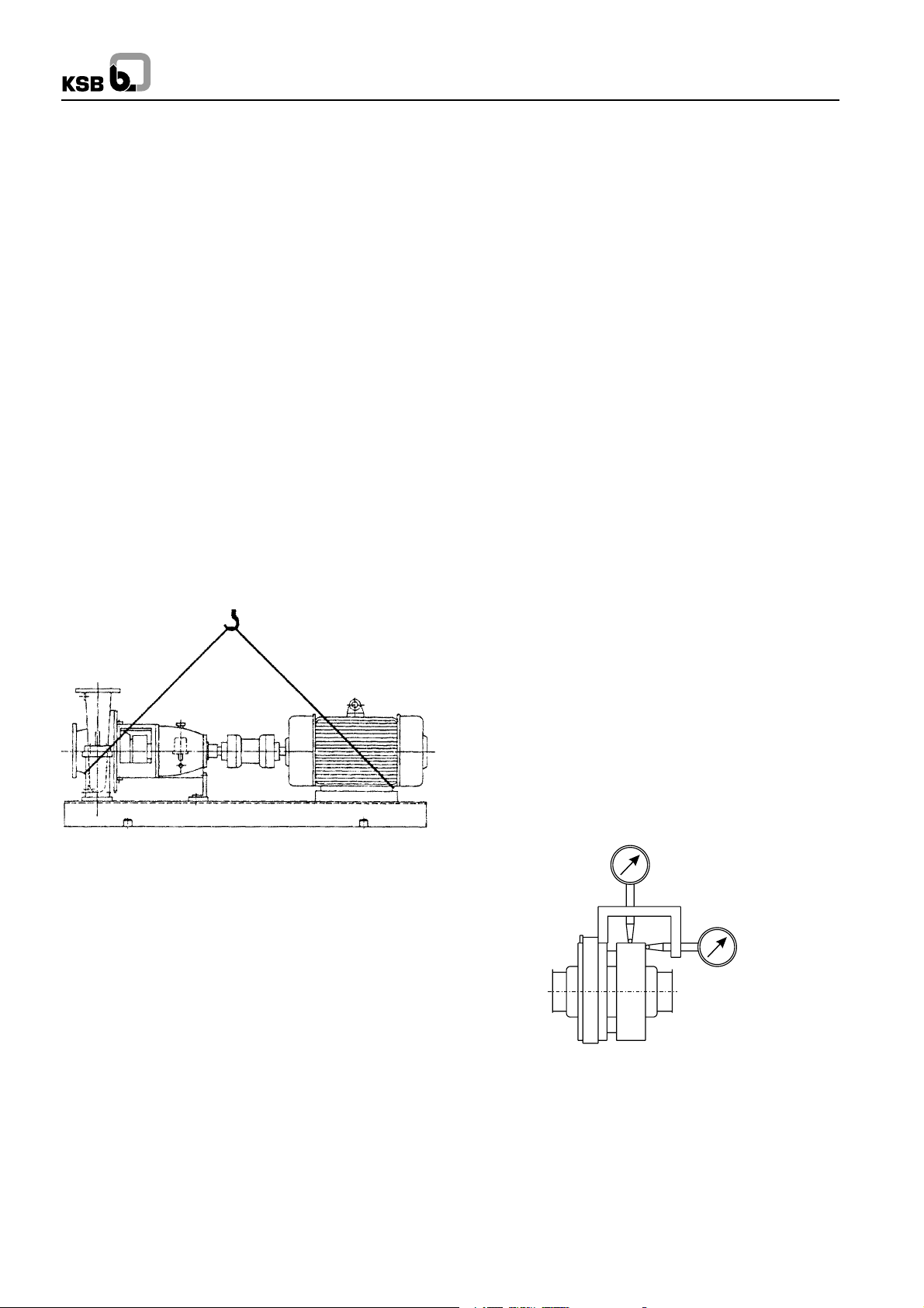
1.1 Handling
The Pump set should be properly handled and slung for
transport. Do not thread the ropes through the eye bolt on the
motor. (See Fig. 1)
During handling do not remove the rubber blankings provided
on the suction and discharge nozzles.
Fig. 1 : Pump and driver mounted on a combined baseplate
6. Grout the foundation bolts and the packer plate (if
applicable) by using quick setting non-shrink cement,
ACC make “Shrinkkomp” or FORSORC make
“Conbextra-GP2” or equivalent.
7. Allow curing time of 24 to 72 hours depending upon the
grout used.
8. Remove bolts which are holding packer plates with the
base frame (if applicable).
9. Carry out final levelling by inserting shims (S.S. Shims
preferred) between packer plates and base frame (if
applicable).
10. Tighten the foundation bolts and recheck the levelling.
Correct it, if necessary.
11. Grout the complete base frame, including hollow portion,
if any, using conventional grouting mix i.e. portland
cement, sand and aggregate in proportion 1:2:4 and
gravel size not exceeding 20 mm.
12. Plaster the foundation and apply suitable oil resistant
paint.
For figures refer Annexure I.
2.3 Alignment of pump and driver
Accurate coupling alignment requires a coupling alignment
jig. This can be manufactured from 20 x 20 mm steel flat. The
jig should be attached to the shafts. See Fig. 2.
The coupling can be considered correctly aligned with the aid
of the jigs illustrated if the difference measured does not
exceed 0.1 mm both in the radial and axial directions,
measurements being taken in 4 planes at 900 intervals.
Alignment should be checked when the pump is hot
(applicable for pump handling hot fluids), In case any deviation
is found, please check the pipe lines and or realign the pump.
The coupling alignment check should be repeated after the
piping has been connected to the pump to ensure stress free
piping. Prior to alignment, individual concentricity of coupling
should be checked. It should be within 0.03 mm. If not,
corrective action should be taken. The coupling should be
dynamically balanced in accordance with VDI 2060 (ISO
1940)/G6.3 for motor driven pumps and G2.5 for turbine driven
pumps.
2. Installation (on site)
2.1 Foundation
Make sure that the concrete foundation has set firmly before
placing the base frame along with the pump set or pump on
it. The surface of the foundation should be truly horizontal and
perfectly flat. The foundation bolts should be suspended in
the baseplate.
2.2 Base Frame and Pump
Procedure
1. Bolt the Pump on the base frame.
2. Bolt the packer plates on the bottom pads of the base
frame, if applicable.
3. Place the unit on the foundation.
4. Suspend the foundation bolts in the pockets provided on
the foundation block.
5. Level the pump on the delivery flanges or feet within 0.2
mm per mtr., using jacking bolts provided on the corners
of the base frame.
Fig. 2 : Alignment of coupling
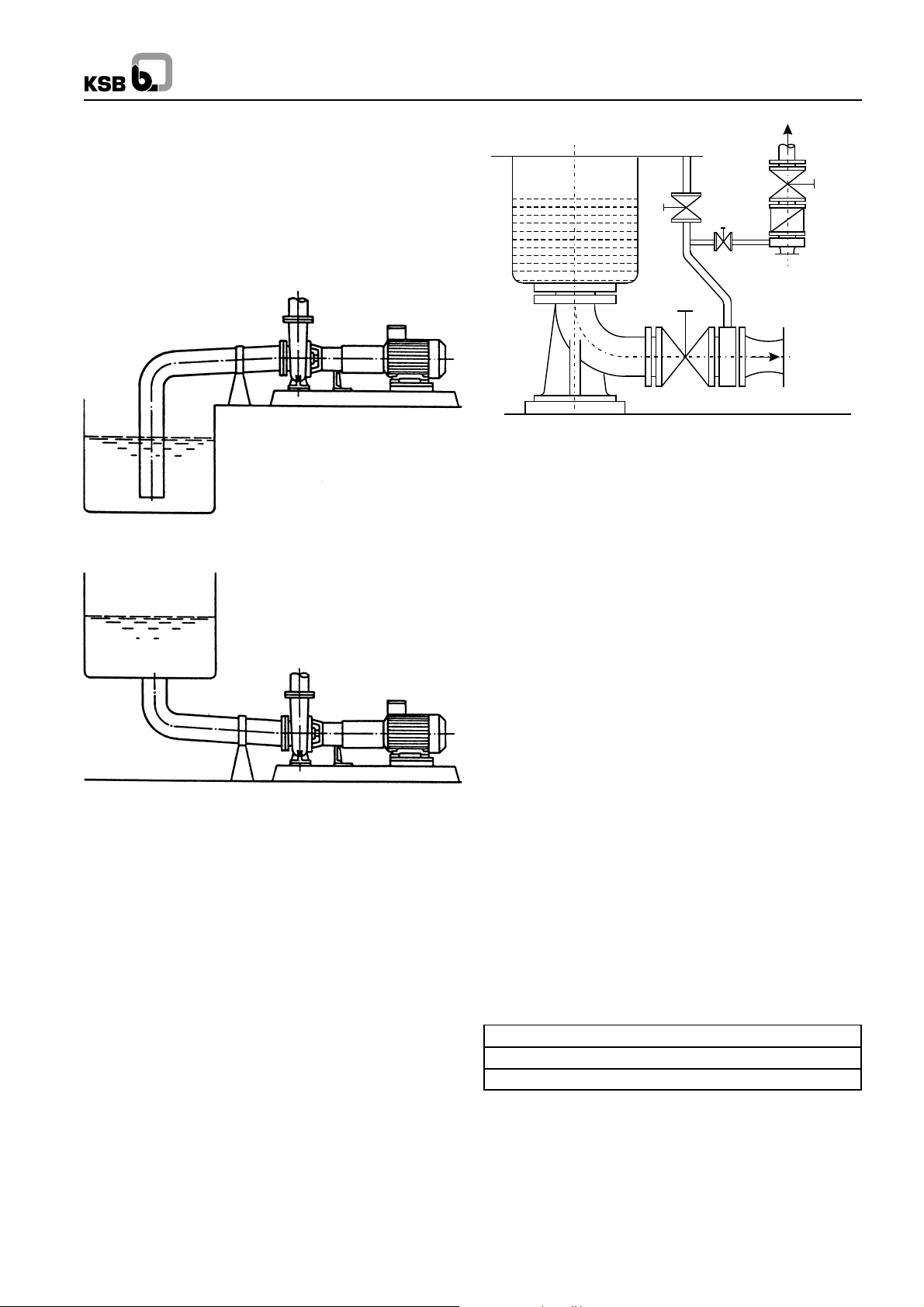
2.4 Connecting the piping
Never use the pump itself as an anchor point for the piping.
Suction lift lines should be laid with a rising slope towards the
pump and suction head line with a downward slope towards
the pump. The pipelines should be anchored in close proximity
to the pump and should be connected to the latter without
transmitting any stress or strain, nor should the weight of the
piping be loaded on to the pump. The nominal sizes of the
1
Page 5
pipelines should be at least equal to the nominal sizes of the
V
B
C
E
R
ZA
Pump
pump nozzle. In case the suction pipeline size is bigger, the
connection should be done by means of an eccentric reducer,
in order to avoid air pockets. We recommended the
incorporation of check valves or non return valves and
isolating valves in the system, depending on the type of
installation and pump. Any thermal expansion of the piping
(due to high temperatures) must be compensated by suitable
means, so as not to impose any additional load on the pump.
CPK
A Main isolating valve R Check valve
B Vacuum balance line V Vessel under vacuum
C Isolating valve Z Intermediate flange
E Vacuum-tight isolating valve
Fig. 5 Suction line and vacuum balance line
Fig. 3
Fig. 4
2.4.1 Auxiliary Connections
The auxiliary connections required for your pump (cooling,
heating, sealing liquid, flushing liquid etc. as the case may
be) are indicated in the installation drawing and on the piping
diagram in respect of size and location.
2.4.2 Vacuum Balance Line
If the pump has to pump a liquid out of a vessel under vacuum,
it is advisable to install a vacuum balance line. This line should
have a nominal size of 25 mm at least. It should be arranged
to lead back into the vacuum vessel at a point above the
highest permissible liquid level. An additional line starting at
the pump discharge nozzle facilitates venting of the pump
before start up. The vacuum-tight isolating valve E in this
connecting line should be closed after the venting procedure
& should remain closed while the pump is running. The main
isolating valve C in the vacuum balance line must remain
open at all times when the pump is running and should be
closed when the pump is shutdown. Refer Fig. 5.
2.5 Coupling Guard
In compliance with the accident prevention regulations, the
pump may only be operated if it is fitted with a coupling guard.
If the customer states specifically that coupling guard is not to
be supplied by KSB, it must be provided by the pump operator.
2.6 Measuring Instruments
Each pump should be equipped with two pressure gauges,
one at the suction nozzle and the other at the discharge nozzle.
Their measuring range should be suitable for the prevalent
pressure conditions, and they should be provided with a stop
cock or stop valve. If the suction conditions demand (e.g.
suction lift operation), the gauge on the suction nozzle should
be pressure vacuum gauge.
2.7 Final check
Check the alignment once more as described in section 2.3. It
must be possible to rotate the pump rotor freely without
additional effort by hand at the coupling.
3. Commissioning, Start-up/Shutdown
3.1 Preliminary remarks regarding commissioning
3.1.1 Lubricants
The bearing bracket should be filled with oil of any one of the
following types and specifications :
Indian Oil : Servosystem 46
Hindustan Petroleum : Enklo 46
Bharat Petroleum : Bharat Hydrol 46
If some other make of oil is used the properties of the oil should
be as follows.
Kinematic viscosity : 46 +4mm2/s at 40 0C
Flash point : +175 0C
Solidification point : 15 0C
Applicable temperature : Higher than permissible bearing
temperature
for 10 0C contact KSB
2
Page 6
CPK
Oil level in bearing
bracket and connection elbow
Drain
plug
Vent or filler
plug
cooling (pH =~ 7). The maximum pressure of cooling water is
10 bar. The cooling water quantities are specified in lpm for
∆t = 150C in Table No. 1.
Inlet temp. : 100C to 300C
Outlet temp. : 450C max.
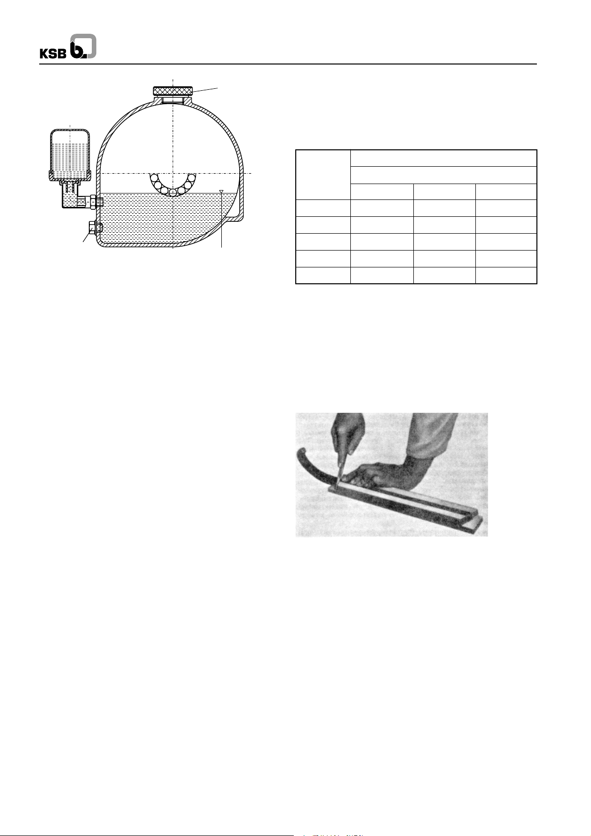
Fig. 6 : Oil fill
Procedure
Unscrew vent plug. Pour in oil through the vent plug aperture
after removing the reservoir of the constant level oiler, until oil
appears in the vertical portion of the connection elbow of the
constant level oiler (see fig. 6).
Then fill the reservoir of the constant level oiler with oil and fit
it back into operating position. Screw vent plug in again. After
a short time has elapsed, check whether the oil level in the
reservoir has sunk. The reservoir should always remain filled.
If the vent plug is inaccessible or difficult to reach e.g. the oil
can be filled into the bearing bracket through the connection
elbow of the constant level oiler.
Bearing
Bracket
P 25/62 5 6 8
P 35/80 6 8 9
P 45/120 9 11 12
P 55/140 12 14 15
P 65/160s 15 17 18
Quantity of cooling water in LPM
Temperature of pumping liquid
Up to 1500C 1500 to 2500C above 2500C
3.1.2.4 Packing the Stuffing Box
Caution :
The pump is despatched from our Works with the stuffing box
packed.
Before repacking, thoroughly clean stuffing box gland (452),
packing compartment and shaft protection sleeve (524).
Cut the packing rings to correct length and ends at 45º. Ensure
that the packing rings ends come into contact with one another
on fitment. (See Fig. 7)
Caution :
The oil level should always be situated below the level of the
vent slot arranged at the top edge of the connection elbow
and this slot should always be perfectly dry. Do not tighten the
elbow by applying force on the reservoir use lock nut for this
purpose.
3.1.2.1. Stuffing Box
The shaft is sealed at its exit through the casing by soft packed
stuffing box or a mechanical seal. Change over from gland
packing execution and vice verca is possible by using
conversion kit. For details refer KSB.
3.1.2.2 Shaft Seal
Soft-packed stuffing box reduce the flow of leakage liquid at
the clearance gap between casing cover and shaft protection
sleeve when the pressure inside the pump is higher than
atmospheric. Conversely, on pumps which operate on suction
lift pressure, the soft-packed stuffing box prevents the ingress
of air into the pump. Sealing is effected by means of soft
packings arranged in a number of rings in the annular space
between the casing cover (161) and the shaft protection sleeve
(524) and lightly compressed by the stuffing box gland (452).
Refer Fig. 8.
3.1.2.3 Cooling of Casing Cover
The casing cover jacket of soft packed stuffing boxes must be
cooled if the temperature of pumped fluid exceeds 900C.
Clean, clear and non aggressive water is recommended for
Fig. 7 : Cutting the packing rings to length.
If the packing rings are either too long or too short, the stuffing
box will not be able to perform its function properly. In the case
of asbestos-graphite packing material, the rubbing faces of
the individual rings should be lightly coated with Molykote
before insertion in the packing compartment. The first packing
ring is then inserted and pushed home into the compartment
with aid of the stuffing box gland (452).
The following packing rings are then inserted into the packing
compartment one by one, making sure that the butt joint of
each ring is offset by 900 approx. in relation to the butt joint of
the preceding ring. The individual rings are pushed home
into the packing compartment with the aid of the stuffing box
gland (452). The packing rings should only be pressed lightly
against one another. They should be inserted in the packing
compartment in such a way that a clear gap of 6 to 8 mm is left
at the outer end of the compartment for the positive guidance
of the stuffing box gland (452).
The inserted packing rings should then be compressed
moderately with the aid of the stuffing box gland (452) and the
nuts (920.03). Then the nuts (920.03) should be slackened
3
Page 7

CPK
again by one to two complete turns, and thereafter tightened
lightly by hand. The correct and even seating of the stuffing
box gland (452) should be checked when the pump is
subjected to suction pressure, by inserting a feeler gauge
between the stuffing box gland (452) and the shaft protection
sleeve (524).
In the case of the special stuffing boxes, a lantern ring is also
inserted in the packing compartment, at the centre of the
compartment (between the packing rings). In these cases,
an information plate is affixed to the casing cover (161),
showing the position of the lantern ring. The lantern ring must
register beneath the drilled hole in the casing cover (161), to
enable the sealing liquid to enter. The pressure of the liquid
should be 1 to 4 bar above the pressure existing in the packing
compartment of the stuffing box.
The packing of the stuffing box should be carried out with
great care, to avoid an excessively high radial pressing force
of the packing rings against the shaft protection sleeve, which
might damage the latter. If the shaft protection sleeve is scored
or grooved, even a new packing cannot be expected to last
very long in service.
A newly packed stuffing box should leak profusely at first. If
this leakage does not cease of its own after a relatively short
period of operation, the nuts on the stuffing box (452) gland
should be tightened slowly and evenly while the pump is
running, until the stuffing box only drips slightly. Make sure
that the stuffing box gland (452) is tightened evenly and not
askew, as otherwise the shaft protection sleeve (524) might
be damaged.
If the newly packed stuffing box starts to emit smoke when the
pump is started up for the first time, the pump should be
switched off. If the smoking persists after the pump has been
started up again and operated several times in succession,
the nuts on the gland should be slackened slightly, or the
stuffing box should be inspected if necessary.
3.1.2.5 Packing Material
When selecting the packing material, make sure it is
compatible with the fluid pumped (consult the manufacturer
in case of doubt).
must be opened fully and the unimpeded flow through these
lines must be verified. Open the isolating valve in the vacuum
balance line (if applicable to your installation) and close the
vacuum tight isolating valve ‘E”. (see Z fig.5).
3.1.4 Checking the direction of rotation
The direction of rotation must correspond to the arrow on the
pump. This can be checked by switching on the driver for a
short instant and switching it off again immediately. Mount the
coupling guard after checking the direction of rotation.
3.2 Start up
Always make sure that the isolating valve in the discharge
line is closed when the pump is switched on. Only after the
pump has attained full operating speed should the discharge
valve be opened gradually and the operating point conditions
adjusted by means of this valve.
Caution :
After the operating temperature has been attained and/or in
the event of leakage, tighten the Bearing bracket lantern to
casing connection bolts after switching off the pumping set. If
the leakage persists, check/change the gasket.
3.3 Shut down
Close isolating valve in the discharge line. If non-return valve
or a check valve has been incorporated in the discharge line,
the isolating valve can remain open so far as there is a back
pressure present in the line. Switch off driver. Observe the
pumping set running down smoothly and quietly to a standstill.
In the event of a prolonged shutdown, the isolating valve in
the suction lift line should be closed.
The shaft seal of pumps which are connected to a supply
vessel under vacuum must be fed with flushing liquid even
when the pump is switched off. In the event of frost and/or of
prolonged shutdowns, the pump and the cooling
compartments (if applicable) must be drained or otherwise
protected against freezing using suitable antifreeze solution.
4. Maintenance and lubrication
Packing material which has been kept in store for a certain
period has a longer service life than standard fresh packing
material from the packing manufacturer. Packing material fitted
in the pump while despatching are :-
CPK G/GC : Style 1003
E/EC : Style 1003
C : Style 1003
CPK EY : Graphoil
3.1.2.6 Sealing liquid
In case of soft packed pumps working under vacuum, handling
impure liquids, sealing liquid is required to be fed through
lantern ring connection. For this the GA drawing of the pump
should be referred to.
3.1.3 Alternate packing arrangements available
The pump suction lift line must be vented and primed with the
fluid pumped before start up. This valve in the suction lift line
must be fully open. All auxiliary connections provided on your
pump (e.g. flushing liquid, sealing liquid, cooling liquid etc.)
4.1 Supervision of operation
The pump should run quietly and free from vibration at all
times. The pump must never be allowed to run dry. Avoid any
prolonged running against a closed discharge valve.
The bearing temperature may be allowed to attain up to 500C
above room temperature but should not exceed 800C.
Make sure the oil level is adequate (see section 3.1.1). The
isolating valves in the auxiliary feed lines must always remain
open when the pump is running.
The soft packed stuffing box (if your pump has one) should
drip slightly during operation. The stuffing box gland should
only be tightened lightly.
Any standby pumps in the pumping installation should be
operated once a week for a short instant, by switching on and
switching off again, so as to maintain them in good condition
for instant start-up in case of emergency. The correct
functioning of the auxiliary connections should be kept under
observation. When signs of wear become apparent on the
4
Page 8

CPK
flexible coupling elements in the course of time, these element
should be replaced by new ones in good time. Otherwise
unbalance vibration will increase leading to failure of coupling.
It is necessary to maintain a log book on hourly basis, where
the suction and discharge pressure, flow rate, bearing
temperatures (pump end and motor end), motor current and
voltage should be noted.
4.2 Bearings and lubrication
4.2.1 Lubricant quantities
The anti-friction bearings are oil lubricated; Required lubricant
fills for different. brg. bkts are as under :-
Standard Bearing Assembly
Bearing Deep groove ball bearings Oil fill in
bracket 321.01/02 DIN 625/C3 bearing litres
clearance
P25/65 6305 C3 0.2
P35/80 6307 C3 0.5
P45/120 6409 C3 0.5
P55/140 6411 C3 1.5
Heavy duty bearing assembly
Bearing Cylindrical roller Angular contact Oil fill
Bracket bearing 322 ball bearing 320 in litres
P25/62s NU305 C3 7206BG 0.2
P35/80s NU307 C3 7307BG 0.5
P45/120s NU311 C3 7311B.TVP.UA80 0.5
P55/140s NU313 C3 7313B.TVP.UA80 1.5
P65/160s NU413 7315B.TVP.UA80 1.8
Table No. 2 Arrangement of bearings & quantity of oil.
4.2.2 Oil change
The first oil change should be carried out after 300 hours of
operation approx. and subsequent oil changes once every
3000 hours of operation approx. In case of newly replaced
bearings, the oil should be changed after 200 hours of running
and thereafter every 1000 working hours.
4.2.3 Procedure
Unscrew oil drain plug beneath the constant level oiler and
drain off the old oil. When the bearing bracket is empty, replace
the oil drain plug and fill in fresh oil in accordance with
section 3.1.1.
4.3 Preservation
If the pump is taken out of service for a prolonged period, it is
advisable to dismantle it completely. Proceed as described
in section 5.2 “Dismantling”. All components should be
thoroughly cleaned, dried and all bright components coated
with grease. Thereafter the pump should be reassembled.
All apertures on the pump should be plugged with wooden
cover plates fitted with O rings. A sachet filled with silicagel
(silicagel absorbs moisture) should be attached to the inside
faces of the oil soaked wooden cover plates on the suction
and discharge nozzles (i.e. inside the nozzles).
The packing should be removed from the stuffing box
compartment and it should be sealed by oil-soaked wooden
half tubes, each provided with two O-rings, in order to prevent
the penetration of moisture (not applicable to pumps fitted
with mechanical seals).
Caution :
Use acid free oils and greases only, when preserving the
pump.
5 Special Instructions
5.1 General Precautions
Before commencing dismantling .
Make sure that the pump will not be accidentally switched on.
The isolating valves in the suction and discharge line must be
closed.
The volute casing must have cooled down to ambient
temperature. The volute casing must be drained and
pressureless.
Always refer to the relevant sectional drawing when
dismantling and reassembling the pump.
5.2 Dismantling
5.2.1 Soft-packed stuffing box
Refer fig. 8.
1. Drain the oil in accordance with section 3.1.1.
2. Remove the coupling guard.
3. Disconnect coupling spacer, or if no spacer is fitted
remove the driver.
4. Disconnect and remove the auxiliary connections on
your pump.
5. Loop a rope tightly around the top stay of brg bkt. lantern.
6. Unscrew hex head bolt (901.02) and the base frame
fixing bolts of support foot (183) and remove the support
foot.
7. Unscrew hex nuts (920.01) and pull the complete
bearing bracket together with casing cover, shaft,
impeller and bearing bracket lantern out of the volute
casing. Use jack bolts for assistance in doing this having
first cleaned the threads. Take care not to damage
gasket (411.03).
8. Unscrew impeller nut (922) with its Heli-coil insert (right
handed screw thread), remove gasket (411.31) and
washer (551.13), pull off impeller (230), remove key
(940.01).
9. Remove stuffing box gland (452) together with stuffing
box pressure ring (454) after having unscrewed hex
nuts (920.02).
10. Remove Casing cover 161 remove gaskets (411.10) &
O-ring (412.01). Next remove stuffing box packing 461
& lantern ring (458). Then remove neck ring after
unscrewing screws (900).
11. Pull shaft protection sleeve (524) together with gasket
(411.32) & washer (551.32) and splash ring (507) off
the shaft.
12. Unscrew hex nuts (920.02) and remove bearing
bracket lantern, (344).
13. After having unscrewed allen head screw in the
coupling hub, pull the coupling half of the pump shaft
5
Page 9

CPK
with the aid of an extractor device and remove key
(940.02).
14. After having unscrewed Allen head screws (914.01/
02) in coupling hub dismantle bearing covers 360.01
and 360.02 at pump and drive ends together with flat
gaskets (400.01/02), oil seals (421.01/02) / Lantern
rings (423.01/02) as applicable.
14.1 Standard bearing assembly :
14.1.1 Carefully remove the shaft (210) together with deep
groov ball bearing (321.02) out of the bearing bracket.
14.1.2 Heat up the deep groove ball bearings and pull them
off the shaft.
14.2 Heavy duty bearing assembly :
14.2.1 Carefully remove the shaft (210) together with angular
contact ball bearings (320) and inner race of cyl. roller
bearing (322) towards the drive end of the pump.
14.2.3 Remove roller cage of cyl roller brg (322) from the
bearing bracket. Then remove spacer ring (504.2) &
circlip.
14.2.4 Bend back lock washer (931); unscrew bearing nut
(923) (righthanded screw thread) remove lock washer.
14.2.5 Heat up angular contact ball bearings (320) and the
inner race of cylindrical roller bearing (322) and pull
them off the shaft. Remove spacer ring (504.01) (applies
only to bearing bracket size 25/62s).
14.2.6 Clean all the components and examine them for signs
of wear. Touch up the damaged components or replace
them by new ones, if necessary.
5.2.2 Mechanical seal stuffing box :
1. Unscrew hex nuts (920.2) and pushback mechanical
seal cover (471) until it abuts against splash ring (507).
2. Dismantle casing cover 161 together with O - ring 412.1
3. Pull the complete mechanical seal together with shaft
protection sleeve 524, mechanical seal cover 471, and
splash ring 507 off the shaft.
5.3 Reassembly
The pump should be reassembled in accordance with the
rules of sound engineering practice. The fits of individual
components should be coated with graphite or other suitable
lubricants before assembly and the same applies to screwed
connections.
O-rings and radial shaft seal rings should be examined for
signs of damage and replaced by new ones, if necessary.
Flat gasket should in principal be replaced by new ones and
make sure that the thickness of the new gasket is exactly the
same as that of the old one.
Reassembly proceeds in reverse sequence to dismantling.
The following points should be carefully observed.
Use only the bearing types and sizes specified in section
4.2.1. The antifriction bearings 320/321.01/02 and inner race
of antifriction bearing 322 (when applicable) should be
preheated in an oil bath to 800C approx. before being slipped
on to the shaft until they abut against the shaft shoulder.
Caution :
1. For heavy duty bearing bracket, the antifriction bearings
320 must be mounted in O-arrangements (see sectional
drawing) Remember the spacer rings 504.01/02 for
normal/heavy brg bkts.
2. When the bearings 320 have been mounted, the
bearing nut 923 without the lock washer 931, must be
screwed on firmly with the aid of a hook spanner. (Do
not use a hammer).
3. The bearing nut must be removed again, the lock
washer inserted and the bearing nut screwed on firmly
again with the hook spanner (Do not use a hammer).
Bend lock washer forward to lock the nut.
4. Take care not to damage the oil seal rings 421.01/02
(when applicable) when mounting bearing covers
360.01/02.
5. The impeller nut should be tightened firmly. The
impeller nut should be tightened a new some 20 to 30
minutes after the initial tightening. Refer Annexure II
for details of metallic washer fitment in impeller.
6. After assembly into the volute casing which has
remained in situ in the piping the coupling alignment
should be checked (see section 2.3).
7. Fill in oil in accordance with section 3.1.1.
5.3.1 Reassembly of stuffing box packing
Assembly recommendations (when pump is dismantled)
Clamp casing cover 161 in a vice, or keep it on an assembly
table and slip in neck ring 456. Then insert the first packing
ring with its butt joint lying in the horizontal plane.
Hold the packing ring tight and slip the shaft protection sleeve
into the packing compartment from the pump end, chamfered
end first. Open out the internal diameter of the packing ring
slightly with the aid of the shaft protection sleeve by sliding
the latter to and fro. Then pull out the shaft protection sleeve
and insert the second packing ring with its butt joint offset 90
in relation to the butt joint of the first packing ring. Repeat the
opening out process with aid of the shaft protection sleeve.
Then insert lantern ring 458 (if fitted to your pump). Then insert
the remaining packing rings in succession with their butt joints
offset, and repeating the opening out process for each ring.
When the last packing ring has been inserted the shaft
protection sleeve should be left in the packing compartment.
Insert stuffing box ring 454 in such a way that its joint face is at
right angles to the stuffing box gland. Slip stuffing box gland
452 and tighten it lightly only by hand, by means of two hex
nuts 920.02.
Mount the completely packed casing cover together with the
shaft protection sleeve into the pump.
Caution :
The stuffing box should drip slightly when the pump is running.
Any sealing and cooling liquid connections which are in use
must be checked in respect of unimpeded fluid flow from time
to time.
When the stuffing box gland has been tightened repeatedly
(during use) until it abuts, it is time to repack the pump
completely with new packing.
0
6
Page 10

Fig. 8 Stuffing box dimensions
CPK
5.4 Cooling / Heating
Clean, clear and non-aggressive water is recommended for
cooling. Recommended pH value is 7.
Cooling to stuffing box :
Please follow the instruction given in point no. 3.1.2.3.
Sealing liquid / cooling of stuffing box gland :
For stuffing box with packings, clean solid free liquid at a
pressure of 1 bar above the pressure in stuffing box and at a
flow rate of 2-3 lpm is recommended.
Pressure (maximum) : 6 bar
Recommended temperature : 10 0C to 30 0C.
Bearing Dimensions of Cross Packing
bracket Packing compart- Section rings
ment in mm. packing
Ø di Ø da L
P25/62 35 51 53 8 x 8 4 rings and
P35/80 45 65 64 10 x 10 1 lantern
P45/120 55 75 64 10 x 10 ring or
P55/140 70 95 79 12.5 x 12.5 6 rings w/o
P65/160s 80 105 79 12.5 x 12.5 lantern ring
Table No. 3
See section 5.4.3 for corelation between pump and bearing
bracket sizes.
in mm.
5.3.2 Reassembly of Mechanical seal
Mount the mechanical seal as described in the instructions of
seal manufacturer. The following points should be observed
when mounting the mechanical seal :
Extreme care and cleanliness during assembly are the
essential prerequisites for the trouble free operation of the
mechanical seal.
The guard protecting the sealing faces should only be
removed only at the time of its fitment before assembly.
Cooling to bearing bracket :
No cooling shall be given to the bearing bracket up to a working
temperature of 200 0C.
For working temperature > 200 0C, use following data :
Cooling water qty. : 3 lpm.
Pressure (max.) : 10 bar
Recommended temperature : 10 0C to 30 0C.
Cooling to Pedestal
In case of centre feet mounted CPK Pumps, cooling to pedestal
is recommended for working temperature above 250 0C. The
cooling can be arranged in parallel or in sereis with the bearing
bracket.
Cooling water qty. :
In series with the bearing bracket (e.g. API Plan G) : 5 lpm.
In parallel with the bearing bracket (e.g. API plan G1) : 3 lpm
Pressure (max.) : 6 bar
Recommended temperature : 10 0C to 30 0C
Heating
The space between casing cover and bearing bracket can
also be used for heating by hot water, steam or any other
suitable heat transfer media.
Maximum temperature : 183 0C
Maximum Pressure : 10 bar.
When the stationary seal ring has been inserted, check its
plane parallelism in relation to the casing cover. The surface
of the shaft protection sleeve must be absolutely clean and
smooth and mounting edge of the sleeve must be chamfered.
When slipping the rotating assembly of the seal on to the
shaft protection sleeve take suitable steps to protect the
surface of the shaft protection sleeve against damage.
Before final mounting in the pump, the rubbing faces of the
mechanical seal should be wetted with a drop or two of silicon
oil. In the case of pumps equipped with a double acting
mechanical seal, the mechanical seal compartment must be
properly vented and pressurized to the correct pressure
specified in the installation drawing (it should remain under
pressure even when the pump is stopped).
The supply of quench liquid must remain turned on even when
the pump is stopped.
Fig. 9 : Stufing box arrangement of CPK Y Pumps.
7
Page 11

Bearing Dimensions of Cross Packing
bracket Packing compart- Section rings
ment in mm. packing
Ø da Ø di L
P25/62 35 51 53 8 x 8
P35/80 45 65 64 10 x 10
P45/120 55 75 64 10 x 10 6 nos.
P55/140 70 95 79 12.5 x 12.5
P65/160 80 105 - 12.5 x 12.5
in mm.
5.5 Spares
5.5.1 Ordering spare parts
Please quote the following information when ordering
spares
Part Name :
Pump type : CPK in this case with appropriate size
Part No. :
Serial No. :
Works Order No. :
The above details are stamped on the name plate.
CPK
8
Page 12

6 Interchangeability of pump components
CPK
Bearing
bracket
P25/62
P35/80
Pump
size
Angular contact ball brg. (set)
322 Cylindrical Roller bearing
330 Bearing bracket
344 Bearing bracket lantern
433 Mechanical seal
452 Stuffing box gland
456 Stuffing box pressure ring
457 Neck ring
458 Lantern ring
461 Stuffing box packing
471 Seal cover
502 Wearing ring
507 Splash ring
524 Shaft Protection sleeve
161 Casing Cover
183 Support foot
210 Shaft
320
Part No. Designation
32-125 1 1 1 1 1 1 1 1 1 1 1 1 1 1 1 1 1 1 1 1
32-160 2 2 1 1 1 1 1 2 1 1 1 1 1 1 1 1 1 1 1 1
40-160 2 2 1 1 1 1 1 2 1 1 1 1 1 1 1 2 1 1 1 1
50-160 2 3 1 1 1 1 1 2 1 1 1 1 1 1 1 3 1 1 1 1
32-200 3 3 1 1 1 1 1 3 1 1 1 1 1 1 1 1 1 1 1 1
40-200 3 3 1 1 1 1 1 3 1 1 1 1 1 1 1 2 1 1 1 1
50-200 3 3 1 1 1 1 1 3 1 1 1 1 1 1 1 3 1 1 1 1
80-160 4 5 2 2 2 2 2 4 2 2 2 2 2 2 2 10 2 2 2 2
65-200 5 5 2 2 2 2 2 5 2 2 2 2 2 2 2 8 2 2 2 2
80-200 5 5 2 2 2 2 2 5 2 2 2 2 2 2 2 10 2 2 2 2
100-200 5 6 2 2 2 2 2 5 2 2 2 2 2 2 2 12 2 2 2 2
32-250 6 5 2 2 2 2 2 6 2 2 2 2 2 2 2 6 2 2 2 2
40-250 6 5 2 2 2 2 2 6 2 2 2 2 2 2 2 5 2 2 2 2
50-250 6 5 2 2 2 2 2 6 2 2 2 2 2 2 2 4 2 2 2 2
65-250 6 6 2 2 2 2 2 6 2 2 2 2 2 2 2 8 2 2 2 2
80-250 6 7 2 2 2 2 2 6 2 2 2 2 2 2 2 11 2 2 2 2
40-315 7 6 2 2 2 2 2 7 2 2 2 2 2 2 2 5 2 2 2 2
50-315 7 7 2 2 2 2 2 7 2 2 2 2 2 2 2 7 2 2 2 2
321.1/2 Deep groove ball bearing
648 Drip plate
922 Impeller nut
100-250 8 8 3 3 3 3 3 6 3 3 3 3 3 3 3 13 3 3 2 3
125-250 8 9 3 3 3 3 3 6 3 3 3 3 3 3 3 15 3 3 2 3
150-250 8 10 3 3 3 3 3 6 3 3 3 3 3 3 3 16 3 3 2 3
65-315 9 8 3 3 3 3 3 7 3 3 3 3 3 3 3 9 3 3 2 3
P45/120
P55/140
P65/160s
Note : Part nos. 102 impeller & 230 Volute casing respectively cannot be used in other pump sizes.
80-315 9 9 3 3 3 3 3 7 3 3 3 3 3 3 3 12 3 3 2 3
100-315 9 9 3 3 3 3 3 7 3 3 3 3 3 3 3 14 3 3 2 3
125-315 9 10 3 3 3 3 3 7 3 3 3 3 3 3 3 16 3 3 2 3
80-400 10 10 3 3 3 3 3 8 3 3 3 3 3 3 3 12 3 3 2 3
100-400 10 10 3 3 3 3 3 8 3 3 3 3 3 3 3 14 3 3 2 3
125-400 10 11 3 3 3 3 3 8 3 3 3 3 3 3 3 15 3 3 2 3
200-250 11 13 4 4 4 4 4 9 4 4 4 4 4 4 4 17 4 4 3 4
150-315 12 12 4 4 4 4 4 10 4 4 4 4 4 4 4 18 4 4 3 4
200-315 12 13 4 4 4 4 4 10 4 4 4 4 4 4 4 19 4 4 3 4
250-315 12 16 5 4 4 4 4 10 4 4 4 4 4 4 4 21 4 4 3 4
150-400 13 12 4 4 4 4 4 11 4 4 4 4 4 4 4 18 4 4 3 4
200-400 13 13 4 4 4 4 4 11 4 4 4 4 4 4 4 20 4 4 3 4
200-500 16 17 6 5 5 5 12 5 5 5 5 5 20 5 5 3 5
250-400 15 17 6 5 5 5 11 5 5 5 5 5 22 5 5 3 5
250-500 16 15 6 5 5 5 12 5 5 5 5 5 23 5 5 3 5
9
Page 13

7 Recommended stock of spare parts for 2 years of operation
Part No. Designation Number of pumps (including stand by pumps)
2 3 4 5 6 8 10 and more
No. of spare parts
210 Shaft 1 1 2 2 2 3 30%
230 Impeller 1 1 2 2 2 3 30%
320 Angular contact ball bearings (set) 1 1 2 2 2 4 50%
CPK
321.01/02
322 Cylindrical roller bearing 1 1 2 2 3 4 30%
330 Bearing bracket - - - 1 1 1 2 per 10 nos.
433 Mechanical seal Refer works
454 Stuffing box pressure ring 1 1 2 2 2 3 30%
456 Neck ring 1 1 2 2 2 3 30%
458 Lantern ring 1 1 2 2 2 3 30%
461 Stuffing box packing (set) 2 2 3 3 3 4 40%
502 Casing wear ring 2 2 2 3 3 4 50%
503 Impeller Wear ring 2 2 2 3 3 4 50%
524 Shaft protection sleeve 2 2 2 3 3 4 50%
Deep groov ball bearing 1 1 2 2 2 4 50%
Gaskets (set) and O ring 4 6 8 8 9 12 150%
8. Faults
8.1 Faults, causes and suggested remedies.
Faults Code Number
Cause-remedy
Pump delivers insufficient 1,2,3,4,5,6,7,8,9,
liquid 10,11,18,28
Driver is overloaded 12,13,14,15,23,27,28
Excessively high pump 15
discharge pressure
Excessively high bearing 22,23,24,25,26
temperature
Leakage at the pump 29
Excessively leakage at 17,18,19,20,21,22,23,33
shaft seal
The pump runs rough 3,6,11,12,22,23,30,31,32
Excessive temperature 3,6,32
rise inside the pump
8.2 Cause-Remedy
1. The pump delivers against an excessively high
discharge pressure
- open discharge valve further until the duty point
conditions have been attained (adjusted)
2. Excessively high back pressure
- fit an over size impeller
- increase rotational speed
(applies to turbine or I.C. engine driven pumps)
3. The pump and/or piping are incompletely vented or
primed.
- vent or prime the pump and system completely.
4. Suction line or impeller clogged.
- Remove deposits in the pump and/or piping.
5. Formation of air pockets in piping.
- Alter piping layout
10
1)
2)
Page 14

CPK
- If necessary fit a vent valve.
6. NPSH available is too low (on positive suction head
installation)
- Check liquid level in suction vessel.
- Open isolating valve in suction line fully.
- Install a different suction line if necessary, if the
friction losses in the suction line are excessive.
- Check the suction line strainer.
7. Excessively high suction lift
- Clean out suction strainer basket and suction piping.
- Check liquid level in the pit.
- Alter the suction line.
8. Entrainment of air through the stuffing box.
- Sealing liquid passages are clogged; clean them
out if necessary, arrange a sealing liquid supply
from an outside source, or increase sealing liquid
pressure.
- Fit a new shaft seal.
9. Reverse rotation.
- Change over two of the phase leads of the power
supply cable.
10. Rotational speed is too low
2) 3)
- Increase rotational speed
- Increase voltage of power supply
11. Excessive wear of the pump internals
- Replace worn components by new ones.
12. Pump back pressure is lower than specified in the
purchase order.
- Adjust duty point accurately by means of the isolating
valve in the discharge line.
- In case of persistent overloading, trim the impeller
if necessary
13. Specific gravity or viscosity of the fluid pumped is
higher than that specified in the purchase order
2)
2)
14. Stuffing box gland tightened excessively or askew
- Adjust the gland as required.
15. Excessive rotational speed
- Reduce speed (applies to turbine or I.C. engine
driven pumps
2) 3)
16. Worn shaft seal
- Check condition of shaft seal and renew it if
necessary.
- Check flushing liquid or sealing liquid pressure.
17. Grooving score marks or roughness on shaft protection
sleeve surface.
- Fit a new shaft protection sleeve
18. Lack of cooling liquid or fouled and clogged liquid
compartment.
- Increase the flow of cooling liquid
- Clean out the cooling compartment
- Clean the cooling liquid itself.
19. Stuffing box gland, and cover or seal cover incorrectly
tightened, wrong type of packing material used.
- Remedy the fault.
20. The pump runs rough
- Correct the suction conditions
- Check alignment of pumping set and realign if
necessary
- Re-balance the pump rotor dynamically
- Increase the suction pressure at pump suction
nozzle.
21. Pumping set misaligned
- Check alignment at coupling and realign the set if
necessary
22. The pump is warped
- Check piping connections and pump fixing bolts.
23. Excessive axial thrust
2)
- Clean out balance holes in impeller
- Fit new casing wear ring.
24. Too much or too little lubricant or unsuitable lubricant
quality.
- Top up lubricant, reduce quantity of lubricant or change
lubricant quality.
25. The prescribed coupling gap has not been maintained
- Restore correct coupling gap in accordance with
the data on the foundation drawing.
26. Operating voltage is too low.
- Rectify.
27. The motor is running on two phases only.
- Replace the defective fuses.
- Check the cable connections.
28. The connecting bolts are slack.
- Tighten the bolts.
- Fit new gaskets.
29. The rotor is out of balance
- Clean the rotor
- Re-balance the rotor dynamically
30. Defective bearings
- Fit new bearings.
31. Insufficient rate of flow
- Increase the minimum rate of flow.
32. Faults in the circulation liquid supply
- Increase the cross section of the circulation liquid
line.
1) The pump should be made pressurless before attempting to remedy faults
concerning parts exposed to pressure
2) Please refer to KSB
3) This fault can be also be remedied by altering the impeller diameter.
11
Page 15

9. Sectional drawing & Part list
CPK
Part No. Description
102 Volute casing
161 Casing cover
183 Support foot
210 Shaft
230 Impeller
321.01/02 Deep groove ball bearings
330 Bearing bracket
344 Bearing bracket lantern
360.01/02 Bearing covers
400.01/02 Flat gasket
411.10/11 Flat gasket - hex. head plug
411.31/32 Flat gasket - impeller nut / impeller
411.46 Flat gasket - drain plug
412.01 O ring
421.01/02 Oil seals
457 Neck ring
502.01 Wearing ring - casing
Part No. Description
503.01 Wearing ring impeller
507.01 Splash ring
524 Shaft protection sleeve
551.31/32 Washer
554 Spring washer
562.02 Cylindrical pin
638 Constant level oiler
901.02 Hex. bolt
901.31 Hex. bolt
902.01/04 Stud
903.01/46 Hex. head plug
913 Vent plug
914.01/02 Allen head screw
916.18 Allen head plug
920.01/04 Hex. head nut
922.01 Impeller nut
940.01/02 Key
12
Page 16

CPK
9.1 Sectional drawing of CPK Y Pumps.
Typical arrangement showing CPK Y Pump with heavy bearing bracket. In case you need more details about the pump
available with you; please contact our Authorised Dealer or KSB office.
Part no. Description Part no. Description
102 Volute casing
502.01 Wearing ring - Casing
904.01 Allen grub plug - Casing wearing ring
903.01 Hex. Hd. Plug - Casing drain
902.01 / 920.01 Stud / Hex. Nut - volute casing
411.10 Gasket - Volute casing
161 Casing Cover
411.11 Gasket - Casing cover
230 Impeller
503.01 Impeller Ring
904.02 Allen grub plug - Impeller ring
922.01 Impeller nut
551.31 / 551.32 Washer - Impeller
411.31 / 411.32 Gasket - Impeller
210 Shaft
940.01 / 940.02 Key
524 Shaft protection sleeve
344 Bearing bracket lantern
902.04 / 920.04 Stud / Hex. Nut - Brg. Bkt / Brg. Bkt.
Lantern
183 Support foot
901.02 Hex. Hd. Bolt - Support foot
554 Spring Washer - Support foot
330 Bearing bracket
322.01 Cylindrical roller bearing
320.02 Angular contact bearing
932.01 / 932.02 Circlip
504.01 / 504.02 Adjusting Disc
931.01 Lock Washer
923 Withdrawl nut
400.01 / 400.02 Gasket - Bearing cover
360.01 / 360.02 Bearing cover
914.01 / 914.02 Socket Hd. Cap Screw - Bearing cover
423.01 / 423.02 Labyrinth ring
507.01 / 507.02 Splash ring
913 Vent plug
638 Constant lever oiler
903.46 / 411.46 Hex. Hd. Plug / Gasket - oil drain
13
Page 17

Annexure I : Arrangement For Base frame Grouting
A. Grouting details for base frame without Packer plates.
CPK
B. Grouting details for foundation bolts.
14
Page 18

C. Grouting details for base frame with Packer plates.
CPK
D. Grouting details for foundation bolts
15
Page 19

CPK
Annexure II : Metallic washer fitment for impeller, impeller nut and shaft protection sleeve
(wherever applicable)
Metal to metal fit of impeller nut (922), impeller (230) and shaft protection sleeve (524) against the shaft shoulder is done as
shown in the sketch and as described in the procedure given below :
This is achieved without reworking of standard parts. However recheck cavity dimensions as shown below and rework only if
required.
Procedure
Spacer washer (551.32) and gasket (411.32) are inserted between shaft protection sleeve (524) and impeller (230). Then the
spacer washer (551.31) and gasket (411.31) are placed between the impeller (230) and impeller nut (922) and finally impeller
nut (922) is tightened.
To calculate g1 & g2 use following formula
1. g1 + F = N + Wf
2. g2 + B = S + Wb
Where wf : front washer thickness
wb : back washer thickness
g1 : front gasket cavity thickness
g2 : back gasket cavity thickness
F : Impeller front length
B : Impeller back length
S : Sleeve length
Bearing
Bracket
Washer thickness Gasket thickness
(mm) (mm)
551.31 551.32 411.31 411.32
P 25/62 1.1 1 1.5 1.5
P 35/80s 2.1 1 1.5 1.5
P 45/120s 2.1 1 1.5 1.5
P 55/140s 2.1 1 1.5 1.5
P 65/160s 3.1 1 1.5 1.5
P 80/200s 5 1 1.5 1.5
Part No. Part Name
210 Shaft
230 Impeller
411.31/32 Graphite gaskets
524 Shaft protection sleeve
551.31/32 Spacer washers
922 Impeller nut
940 Key
Note :
1. When bearing brackets P 55/140s & above; are used,
check if the washer 551.31 rests on the supporting face of
the impeller. If not, rework length of the key.
2. For bearing brackets P 55/140s & above; part no. 551.32
will be in two halves.
Annexure III : Wearing Ring Clearances
Pump size Group 1 Group 3*
up to DN 65 0.4
DN 80-150 0.5
DN 250 & above 0.65
DN 200 0.55
+ 0.1
+ 0.1
+ 0.15
+ 0.1
The clearances are in mm and identical on the suction & discharge side.
* For all CPK C pumps and for CPK E pumps with
temperature > 2800C.
0.6
0.65
0.75
0.65
+ 0.1
+ 0.1
+ 0.15
+ 0.15
16
Page 20

CPK
Annexure IV - Environment Protection - Pruduct Disposal after useful life
Products manufactured by KSB Pumps are designed with utmost care for environmental protection. Innovative designs and
wide product range takes care of specific customer requirements reducing material and electrical energy consumption.
Product materials are recyclable. Our customers are educated with environment friendly methods of disposing product ingredients
at the end of their useful life. Please find herewith methods of disposing used pump ingredients.
Environment Protection measures during product disposal
Sr. Product Ingredients Disposal Methods
1. Pumps Paint : Pump body, Base frame Sludge to be disposed through authorised re processor
Non ferrous parts :
a) Impellers, Diffusers
b) Bushes
c) Stage sleeves
d) Thrust plate To be disposed through authorized re-processor
e) Wearing ring
f) Coupling Guard
g) Brg. Guard
Rubber / Plastic Parts :
a) Cover for NRV
b) Plastic cap To be disposed through authorized re-processor
c) Nozzle blanking
d) Cooling Fan
2. Motor Paint : Motor body, Rotor Sludge to be disposed through authorised re-processor
Non ferrous parts :
a) Support bushes
b) Copper sticks and stampings To be disposed through authorized re-processor
c) Balancing rings
d) Winding wire with varnish
Rubber / Plastic Parts :
a) Oil seal
b) Sand guard To be disposed through authorized re-processor
c) Notch keys, slot insulators
d) Overhang protection pipe
17
Page 21

CPK
Page 22

 Loading...