

Page 1
Operating Instructions
3300.810 / 06 - 85 G3
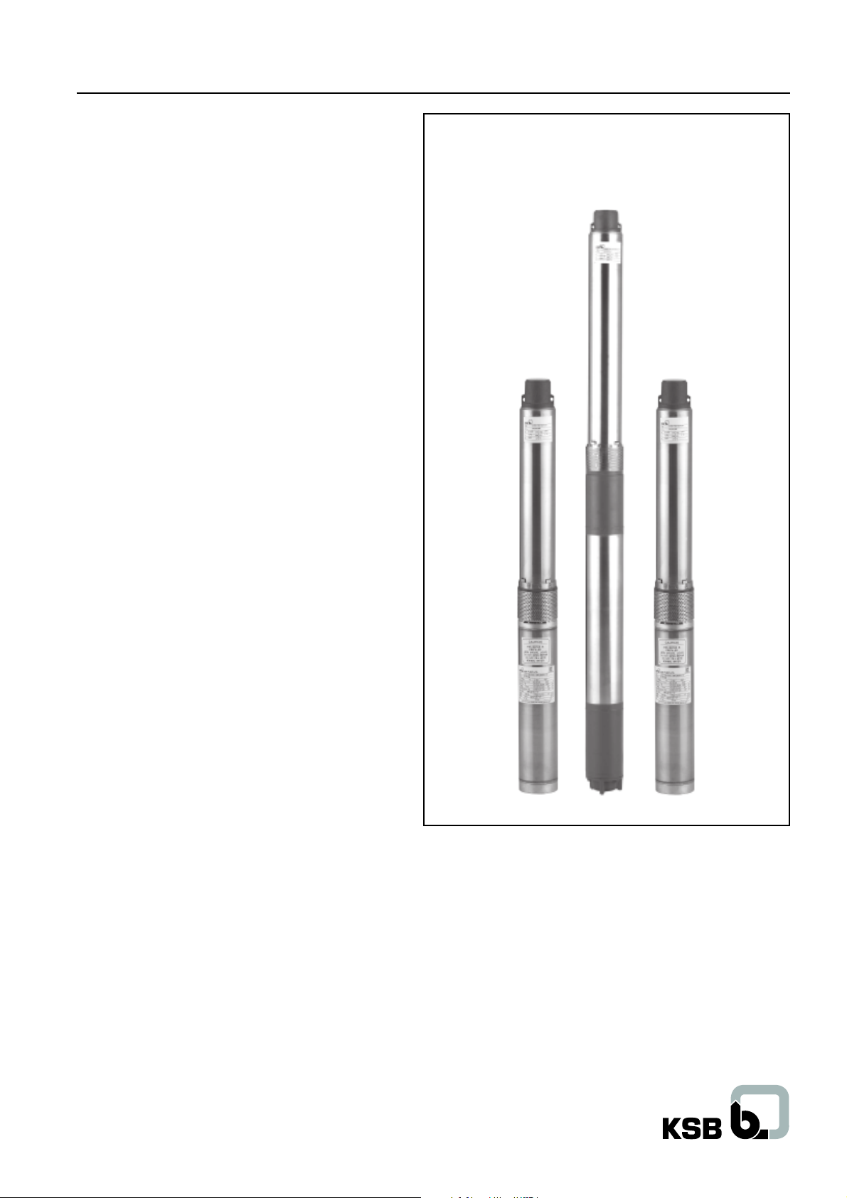
Submersible Motor Pumps (100 mm)
100 mm Submersible Motor Pumps
(50 Hz)
Page 2

Contents
Submersible motor pumps (100 mm)
Sr. no. Description Page no.
1 General 1
1.1 Safety of pumping unit 1
1.1.1 Checks & Safety of pumping unit 1
1.1.2 Instructions on unit (Printed matter) 1
1.1.3 For unauthorized spare part and modifications 1
1.1.4 For unauthorized modes of operation 1
1.1.5 Water characteristics 1
1.2 Description of Product 1
1.2.1 Designation (example) of pump 1
1.2.2 Designation (example) of motor 1
2 Installation 1
2.1 Installation and operational accessories 1
2.2 Motor preparations 1
2.2.1 Motor fill 1
2.2.2 Insulation resistance (IR) 2
2.2.3 Extended Cable connection 2
2.2.3.1 Selection of Cable 2
2.2.4 Coupling of pump and motor 2
2.3 Typical installation at site 3
2.3.1 Vertical installation 3
2.3.2 Horizontal Installation (e.g. in tank or pit) 3
2.3.3 Plastic / Flexible Rubber riser piping instead
of normal GI riser piping 3
2.3.4 Installation of water level guard 4
2.3.5 Protection against electric shock 4
2.3.6 Fixing the power supply cable to the riser pipe 4
2.3.7 Verification of power line with respect to
motor design 4
2.3.8 Trip circuit for over current 4
2.4 Starting mode 4
2.4.1 For single-phase motor 4
2.4.2 For three-phase motor 5
Sr. no. Description Page no.
8 Trouble shooting 8
8.1 Motor 8
8.2 Pump 9
9 Schematic Cross-sectional Drawings 10
9.1 Pump - CORA 100 (Radial flow) 10
9.2 Pump - CORA 18C (Mix flow) 11
9.3 Pump - CORA 2AH, 3AH & 3A (Radial flow) 12
9.4 Motor - UMA 100 13
9.5 Motor - UMA I 100 & UMA I (S) 100 14
9.6 Motor - UMT (S) 100 15
9.7 Motor - XUMA (S) 100 16
Annexure I - Environment Protection Product Disposal after useful life 17
3 Commissioning and start up 5
3.1 Verification of rated current 5
3.2 Switching ON of mains 5
3.3 Checking the direction of rotation 5
3.4 Discharge valve position during initial start-up 5
3.5 Operation against a closed discharge valve 5
3.6 Operation against a throttled discharge valve 5
3.7 Operating limits of pump 5
3.8 Switching frequency 5
3.9 Interruptions / Shutdown periods 6
4 UMT (S) 100 motors 6
4.1 The motor is hermetically sealed induction motor 6
4.2 Connecting the motor 6
4.2.1 Starter panel 6
5 Maintenance 7
5.1 Storage 7
6 Services 7
7 Recommended stock of spare parts for
2 years of continuous operation 7
Page 3
Submersible motor pumps (100 mm)
1 General
Submersible motor pumps by KSB have been developed in
accordance with state-of-the-art of design and manufacturing
technology with extreme care and rigid quality control. The manual
contains important information for reliable operation of pump.
The special feature of these submersible pumps is installation in
narrow deep wells to pump clean water for various applications
like water supply system, irrigation sprinkling systems, ground
water lowering, pressure boosting, fountains etc.
For any additional information or instructions please contact KSB’s
nearest office.
1.1 Safety of pumping unit
This operating manual contains fundamental installation,
operation and maintenance instructions. Hence this must be
clearly understood by concerned people, prior to installation. The
booklet must always be located for easy access at site.
1.1.1 Checks & Safety of pumping unit
Check for any transit damage. After unpacking inspect the pumpmotor for any signs of shaft deflection and for the damage of the
lead cable.
This operating manual does not take into account any safety
regulations those may apply. It’s a pump operator’s responsibility
that any such regulations are adhered to.
1.2 Description of Product
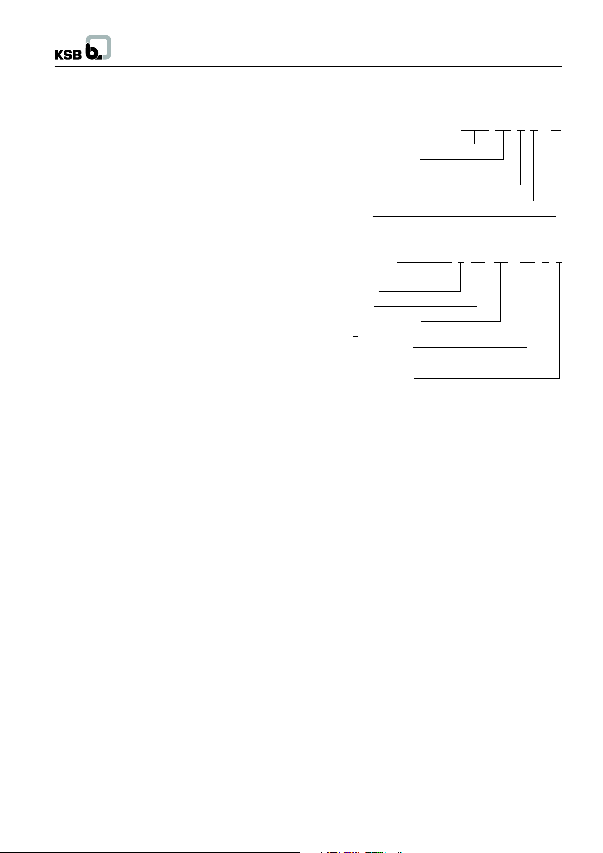
1.2.1 Designation (example) of pump
CORA 100 4 C / 7
Type series
Min. well diameter in mm
(100 mm ~ 4 inches)
Capacity for 50 Hz (in m3/hr.)
Design status
No. of stages
1.2.2 Designation (example) of motor
UMA / XUMA I (S) 100 - 0.8 / 2 1
Type series
Design variant
Single Phase
Min. well diameter in mm
(100 mm ~ 4 inches)
Electrical reference no.
No. of pair of poles
Winding wire insulation
1.1.2 Instructions on unit (Printed matter)
Follow the instructions attached on the motor / pump e.g.
- Arrow indicating the direction of rotation
- Various plugs for water connections viz. filling, venting, draining
etc. on motor
1.1.3 For unauthorized spare part and modifications
Modifications or alterations of the equipment supplied are strictly
not permitted. Original spare parts and accessories authorized
by the manufacturer ensure safety. The use of spurious parts
invalidates any liability of the manufacturer for consequential
damage.
1.1.4 For unauthorized modes of operation
The warranty related to the operation reliability and safety of the
unit supplied is valid only if the equipment is operated according
to designated parameters. The operating limits should not differ
from the limits specified on the nameplate.
1.1.5 Water characteristics
Submersible pumps are designed for handling clean or slightly
contaminated water with the following main characteristics : (As
per IS 8034 : 2002)
a) Turbidity : 50 ppm*, Max. (Silica scale)
b) Chlorides : 500 ppm*, Max.
c) Total Solids : 3000 ppm*, Max
d) pH value : 6.5 to 8.5
e) Temperature : 330 C, Max
f) Specific gravity : 1.004
g) Hardness : 300, Max (Drinking water)
* ppm – parts per million
2 Installation
2.1 Installation and operational accessories
The motor is supplied with a 3 meter long, 3 core waterproof
cable.
The following accessories are necessary for installation and
commissioning :
• A cable with vulcanizing rubber compound (which is normally
used for repairing the punctures in automobiles) and electric
insulation PVC tapes.
• Control panel
• 2 pairs of supporting or installation clamps for vertical
installation and 1 set of stands for horizontal installation.
• Overload trip unit, water level guard, single-phase preventor
(for 3 phase motor).
2.2 Motor preparations
2.2.1 Motor fill
For filling the motor with pure cold drinking water, follow the
procedure given below :
• Place the motor vertically up.
• Remove the two plugs provided at the top of the motor (Here
one plug is provided to escape the air and another for filling
the water).
• Fill the motor completely with pure water having no impurities
(Do not use distilled water).
• After filling the motor let it stand for 30 minutes and rotate the
rotor by hand to accelerate the escape of trapped air.
• At the same time pour more water to fill the loss of volume
caused by the escaped air bubbles.
• Refit the plugs.
• Check the motor completely for any leakages of water.
1
Page 4
Submersible motor pumps (100 mm)
Now motor is ready for operation.
If a unit has been in storage for more than 2 months, check for
the motor filling and for rotor freeness.
2.2.2 Insulation resistance (IR)
The insulation resistance value of the new motor with 500 V DC
megger is generally 20 Mega Ohms. For older motors if the value
observed to be less than 2 Mega Ohms, please contact KSB or
Authorized Dealer before switching on the motor.
2.2.3 Extended Cable connection
Only the proper cable connector ensures a perfect watertight
joint and provides a protection against mechanical damage to
the cable jointing. While connecting extra cable beyond standard
length along with the pump set, it is necessary to have a water
tightened cable joint.
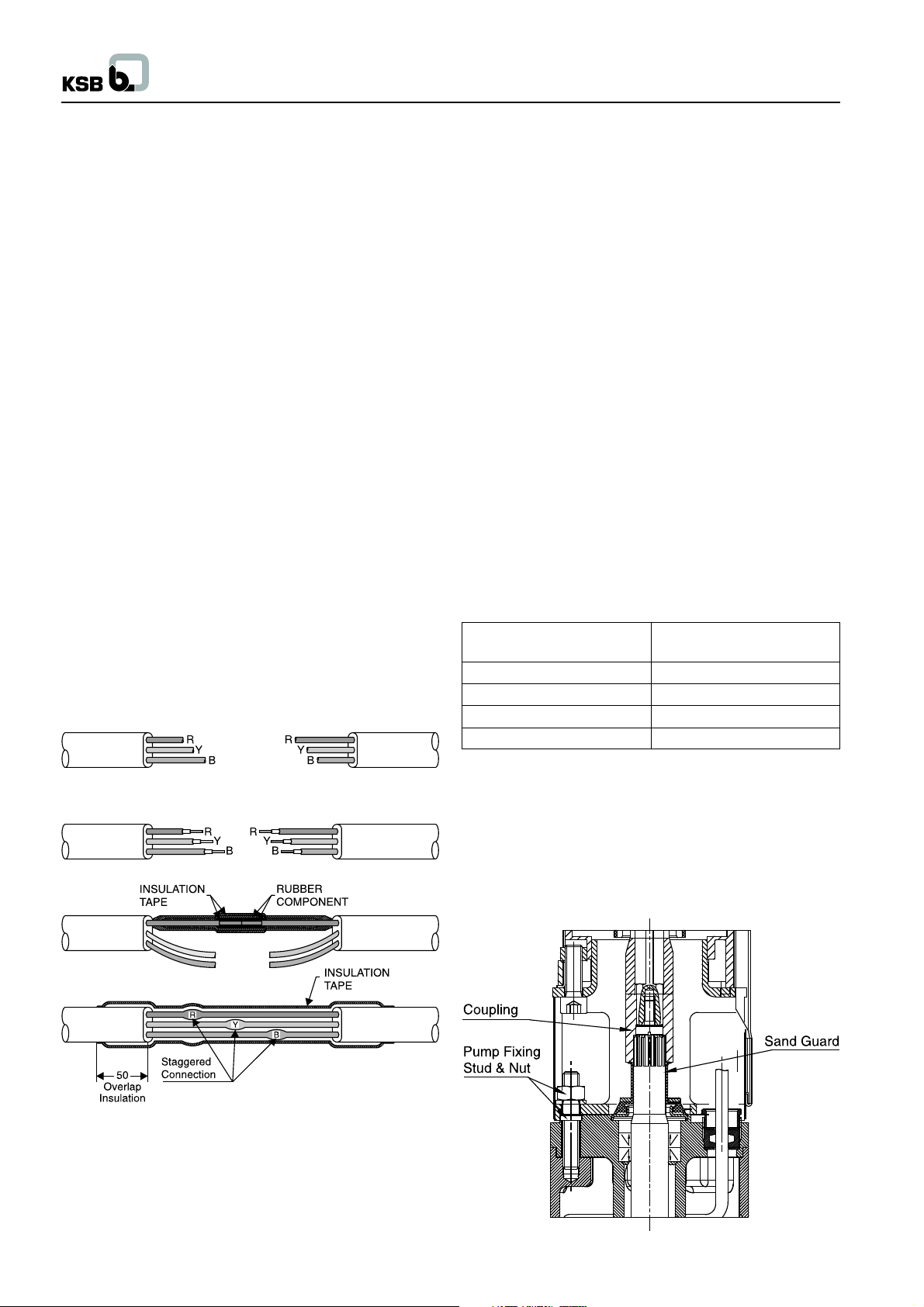
a. To connect the cables, cut off and strip the motor cable and
join it is staggered fashion where no 2 joints overlap each
other.
b. Colors of the leads, which are to be joined together must be
identical as per following sketch (Fig. 1).
c. Wrap vulcanizing rubber compound to each cable joint and
again wrap with electric insulation tape on the top of it.
d. To ensure proper insulation once again wrap with vulcanizing
rubber compound and electric insulation tape for each joint.
e. Finally wind the total cables with electric insulation tape.
f. Oil or grease should not have any contact with the tape.
g. Complete the taping over core insulation at each side.
Please see that each turn of the tape should have a 50% overlap
over the previous turn. The tape should be wound on to a
thickness at least equal to that of core insulation.
2.2.3.1 Selection of Cable
Voltage drop for extended cable should not be more than 3% of
rated voltage i.e.
Permissible voltage drop = Available voltage x 0.03
For Single phase :
Voltage drop = 2 x Cable Length in meters x Resistance / meter
for particular cable size x motor current
Allowed voltage drop is up to 7.0 volts (Considering available
voltage 230 volts).
e.g. For the cable length of 50 m and area of cross section 1.5
mm2, with rated current 3.5 A,
Voltage drop = 2 x 50 x 0.0121 x 3.5
= 4.24 volts (which is permissible)
For three phase :
Voltage drop = Cable Length in meters x Resistance / meter for
particular cable size x motor current
Allowed voltage drop is up to 12.5 volts (Considering available
voltage 415 volts).
e.g. For the cable length of 50 m and area of cross section 1.5
mm2, with rated current 2.4 A,
Voltage drop = 50 x 0.0121 x 2.4
= 1.45 volts (which is permissible)
Resistance / meter according to cross-section area :
Cross - section area Resistance in Ohm / m
(mm2) At 300C
1.5 0.0124
2.5 0.0075
4.0 0.0047
6.0 0.0031
Fig. no. 1
R = Red colored lead
Y = Yellow colored lead
B = Blue colored lead
2.2.4 Coupling of pump and motor
Couple the shaft to motor in vertical manner.
Before fitting the suction strainer the effortless rotation of the
coupled rotor should be checked at the sleeve coupling.
Please ensure that the top face of sand guard presses the bottom
face of the sleeve coupling to avoid the entry of sand inside the
coupling.
Fig. no. 2
2
Page 5
Submersible motor pumps (100 mm)
2.3 Typical installation at site
Use lifting device of capability of carrying the weight of pump
unit as well as the weight of pipe filled with water for installation.
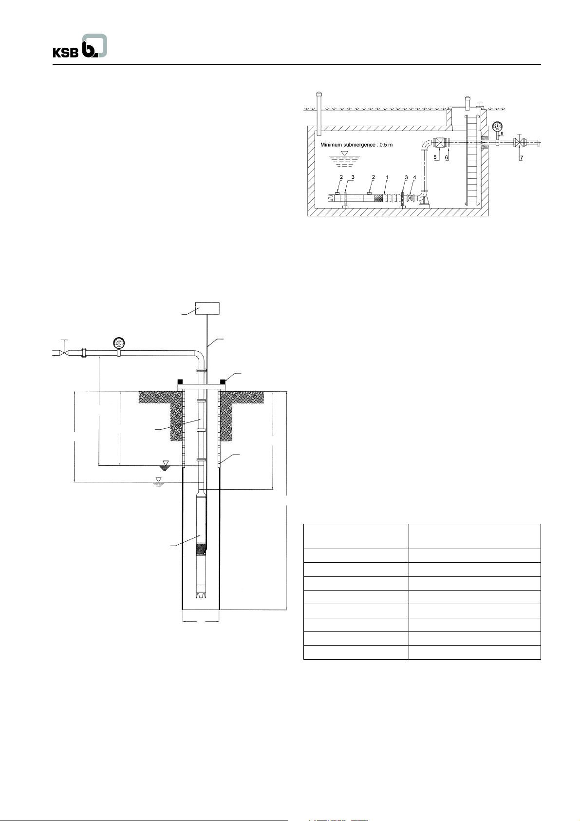
2.3.1 Vertical installation
Before installing the unit in narrow deep wells, the well should be
tested for trueness of size over its entire length (e.g. by running
a dummy cylinder of diameter 98 mm and length about 2 m inside
the well). A slight inclination of the well is immaterial, whereas
any twists or bends can make installation difficult.
Installation depth should be selected such that the motor would
never run dry even when the water level is at its lowest mark
(i.e. draw down of bore well capacity).
The minimum water level should be 0.5 m above the top of the
non-return valve.
The pump should always be installed with the suction strainer
above the slotted casing pipe. The effect is that the pump draws
in the water free from loose sand.
6
H geo
8
H h
3
1
H t
5
2
H e
7
T
2.3.2 Horizontal Installation (e.g. in tank or pit)
Fig. no. 4
1. Submersible pump unit
2. Water reservior for Motor
3. Support
4. Expansion joint
Note : Generally the horizontal installation of submersible pump
unit is equipped with two storage tanks to increase the water
capacity.
1. Referring to the above figure (Fig. 4) for horizontal installation
only two supports are needed. One is placed at the extreme
end of the NRV while other is placed at the center of motor.
2. Install adapter pipe to the pump with 2 Water reservior and
the motor with proper fittings.
3. Ensure that the cast RCC foundation is incorporated with
the recommended foundation bolts of proper height.
4. To make up the correct center height of aligned pump - motor,
provide sufficient metallic packing in the RCC foundation
itself. To attain precise alignment, minor shims up to 2 mm
thick made of M.S. sheet may be used below the pump or
motor stand.
5. Such installed pump shall be either perfectly horizontal or
maximum of 5 degree inclination with motor down and pump
lifted up from the ground. Precise tightening of foundation
bolts has to be done at the final stage.
6. Surface of the motor should be cleaned periodically for
8
effective cooling.
5. Non-return valve
6. Flange adapter
7. Discharge valve
8. Pressure gauge
4
Fig. no. 3
1. Discharge valve
2. Supporting clamp
3. Raiser pipe
4. Submersible motor-Pump set
5. Power supply cable
6. Starter
7. Slotted Casing pipe
(Length up to rock level)
8. Pressure Gauge
D
D = Well diameter
TB = Well depth
He = Installation depth
Hh = Stationary water level
Ht = Operation water level
H
= Geostatic head
geo
Ht - Hh = Drawdown
Notes for installation :
The motor pump unit must be immersed minimum 0.5 m more
below the lowest operation water level Ht.
Pump type Max. no. of stages allowed
for horizontal installation
CORA 1C & CORA 2C 30
CORA 4C 23
CORA 7C 19
CORA 12C 8
CORA 18C 8
CORA 2AH 17
CORA 3AH 12
CORA 3A 15
It is important to ensure that pump does not sit on the base of the
well and there is no risk of sand or sludge deposition around the
motor. This would disrupt heat dissipation from the motor.
2.3.3 Plastic / Flexible Rubber riser piping instead
of normal GI riser piping
Consult the HDPE / rubber pipe suppliers for the capability of
pipes for withstanding the pressure. If the pump is to be fitted
with HDPE raising piping, it is to be firmly tied up with stainless
steel wire ropes of dia. 2-3 mm to the eyelets on the non return
3
Page 6
Submersible motor pumps (100 mm)
valve body and the vertical pipe line. This precaution will help
even in case of GI riser piping.
2.3.4 Installation of water level guard
Install a water level guard for dry running protection to avoid the
damage of pump unit in case of water level fluctuations.
2.3.5 Protection against electric shock
Submersible motors are provided with external earthing plug at
upper bearing body as a standard. A three-cored cable is led out
of the motor. The operator / user shall be responsible for proper
connection of the earthed conductor and of control unit at site.
2.3.6 Fixing the power supply cable to the riser pipe
During installation of pump into the bore well, power supply cable
should be fixed to the raiser pipe by means of cable clips at a
distance of approx. 3 m immediately after the flange or coupling
of the pipe.
2.3.7 Verification of power line with respect to
motor design
Verify the voltage and frequency of main supply with the data
given on the motor’s nameplate.
If it is not matching then consult with concerned electrical
authority.
Ensure that the main power supply is stable.
Typical examples of name plate :
Pump name plate :
KSB PUMPS LTD.
Type : CORA 100 1C/20
Sr. No. : -----
Q : 2.1 m3/hr Year : 2010
H : 48 mtrs kW : 0.75
N : 2800 rpm Ex. :
Motor name plate :
KSB PUMPS LTD.
Type : UMA I ( S ) 100 - 0.75 / 22
Sr. No. : ----
Voltage : 220 V Amp : 11.0
kW / HP : 0.75 / 1.0 Conn : ---
Speed : 2800 rpm Year : 2010
Run Capacitor : 36 uF 440 V Hz : 50 ± 3
Start Capacitor : 50 uF 230 V AC : 1 Ph
For operational values refer the nameplate attached to the pump
unit.
+ 6
- 15
2.3.8 Trip circuit for over current
A temperature compensated over current relay has to be provided
in the operational electrical circuit.
2.4 Starting mode
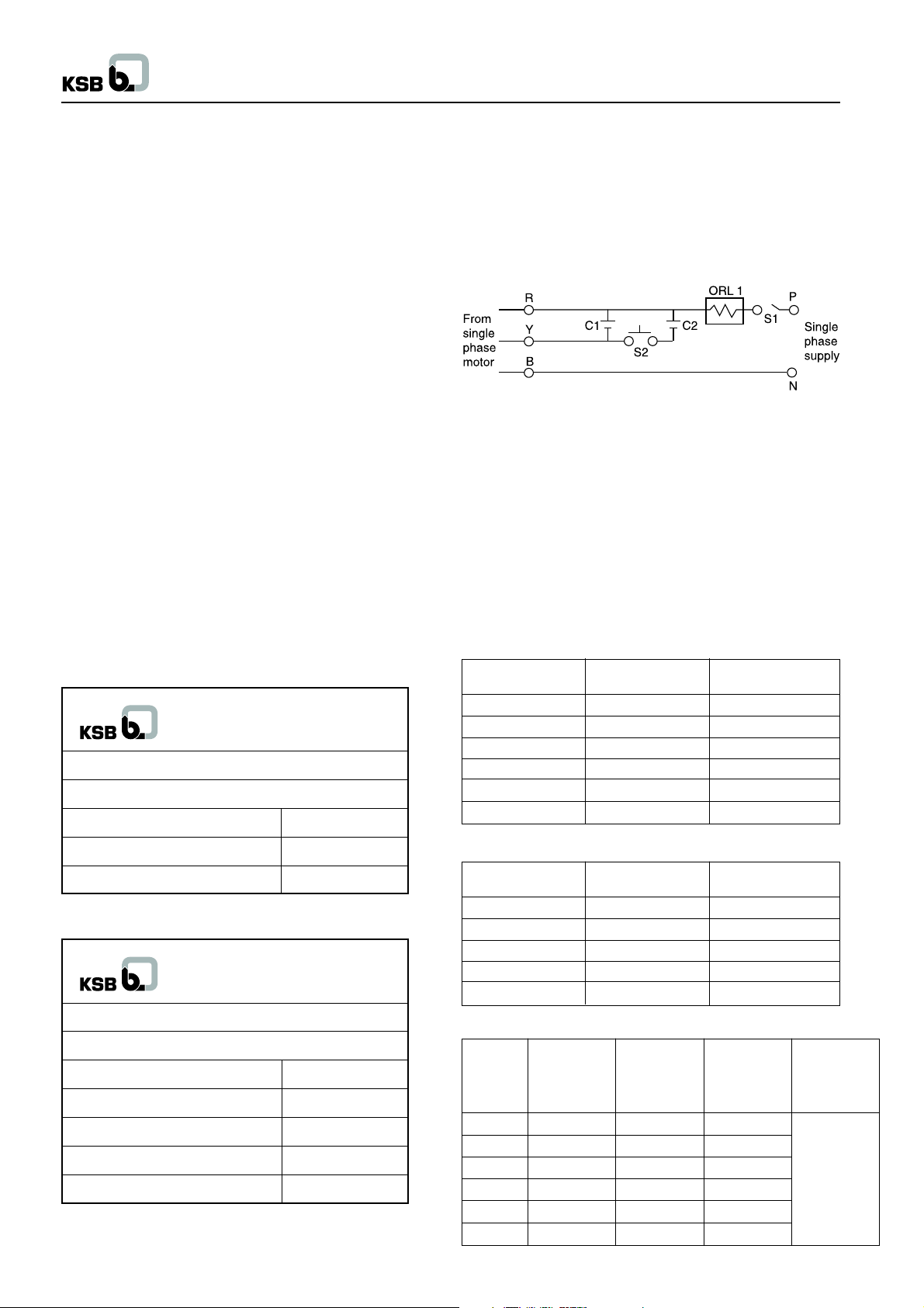
2.4.1 For single-phase motor
Single-phase motor connection diagram of starting method for
DOL is :
R : Red color wire C2 : Starting capacitor
B : Blue color wire C1 : Running capacitor
Y : Yellow color wire ORL 1 : Overload relay
S1 : On-off main switch P : Phase
S2 : Starting push button N : Neutral
Caution :
S2 - Starting push button should be pressed max. for 5 sec. In
case if the motor does not start, continuous operation of this
button may lead to burning the motor.
Capacitor details
C1 : Running capacitor : Polypropylene (440 V)
C2 : Starting capacitor : Electrolytic (230 V)
UMA I (S) 100
Motor capacity Run Capacitor Start Capacitor
kW
0.37 20 60
0.55 20 80-100
0.75 36 80-100
1.1 30 100-120
1.5 30 100-120
2.2 100 120-150
UMA (S) 100
Motor capacity Run Capacitor Start Capacitor
kW
0.5 25 100
0.8 25 100
1.25 36 120
1.5 50 120
2.2 50 200
XUMA (S) 100
Motor Run Start Run Start
Capacity Capacitor Capacitor Capacitor Capacitor
kW
0.37 20 60 - 80 30
0.55 30 80 - 100 30
0.75 36 80 - 100 50
1.1 50 100 - 120 50
1.5 50 100 - 120 100
2.2 100 120 - 150 120
µµ
µF
µµ
(> 180 Volt) (> 180 Volt) (< 180 Volt) (< 180 Volt)
µµ
µF
µµ
µµ
µF
µµ
µµ
µF
µµ
µµ
µF
µµ
µµ
µF
µµ
µµ
µF
µµ
µµ
µF
µµ
Value to be
enhance as
per actual
site
voltage
condition
4
Page 7

Submersible motor pumps (100 mm)
2.4.2 For three-phase motor
2. Using pressure gauge, check the discharge pressure in both
the direction of rotations. The higher value corresponds to
the correct direction of rotation. OR
3. By visual inspection see the flow rate in both cases. If water
comes out up to the short length through the raiser pipe, flow
rate is lower while if it comes farther, results in higher flow
rate. The higher flow indicates the correct direction of rotation.
For Single-phase motors
In case of single-phase AC motors the direction of rotation of the
motor itself corresponds to the correct direction of rotation of the
pump, irrespective of mode of connection to the power supply.
3.4 Discharge valve position during initial start-
up
During initial start-up the pump should run with the discharge
valve slightly open (approx. 1/3 of full opening). The water is
examined for sand content (The permissible sand contents for
warranty is 50 mg / liter) at this stage it is important that pump is
run continuously without stooping (if pump is stop, sand will settle
inside the pump and pump is block resulting in damage) till the
sand content in the water falls to an unnoticeable level OR Flush
the bore well completely before new pump installation.
3.5 Operation against a closed discharge valve
Pumps should not be allowed to run against a closed discharge
valve for longer than 5 minutes. This would cause the water in
the pump to warm up quickly and the heat would be transferred
to the motor, which causes a risk to the motor.
1. Submersible motor
2. Motor cable
3. Cable designation
4. Connected cable
5. Overload relay (thermal type)
6. Leads
7. Electro-magnetic switches
8. Fuses
L1, L2, L3 = Line supply
U, V, W = Leads
N = Neutral
S1, S2 = Push buttons
* Overload relay must be thermal type.
3 Commissioning and start up
3.1 Verification of rated current
Please refer to the motor nameplate for the values of rated current
required for relay setting.
3.2 Switching ON of mains
The pumping set should be switched on only if it is fully immersed
in the water.
3.3 Checking the direction of rotation
For three-phase motors
1. Let the pumping set run for a short time against a closed
discharge valve, in both the directions of rotation and check
the flow. Reversing of two points of connection, reverses
the direction of rotation. The higher flow rate gives the
direction of rotation. OR
3.6 Operation against a throttled discharge valve
If the pump set is to be operated against a throttled discharge
valve for a prolonged period of time, the minimum rate of flow
should be at least 10% of flow at the best efficiency point * (BEP)
of the characteristic curve, this must be observed in order to
reduce noisy operation and the overheating of the pump set.
* For best efficiency point (BEP) of the characteristic curve
consult with KSB dealer.
Actual start-up
• Check the power supply condition as per the name plate.
• Do proper earthling.
• Fix the pressure gauge before discharge valve.
• Set the relay as per current value given on name plate and
start the pump.
• Set the duty parameters as per value given on name plate by
control valve.
• Pump should run always on duty point specified on name plate
3.7 Operating limits of pump
Operational safety requirements stipulate that pump may only
be operated continuously within the flow rate and pump head
limits which are specified on nameplate. Otherwise ±10% of best
efficiency flow rate should be the pump operation range, provided
that motor is not overloaded. (For ensuring this the motor current
should not exceed as specified on name plate).
3.8 Switching frequency
In order to prevent the motor from heating up excessively due to
many switching cycles, a maximum of 15 starts per hour are
permitted with a minimum of 3 minutes interval as a shut down
period between two successive starts.
5
Page 8

Submersible motor pumps (100 mm)
3.9 Interruptions / Shutdown periods
In order to ensure a long motor service life, pumps should not be
allowed to remain idle in water for more than 8 to 10 days.
Otherwise fine deposits like lime, iron and other substances tend
to settle in the bearings and impeller gaps. This might block the
pump rotor. In case the situation is unavoidable, it is
recommended to run the pump for at least 10 to 15 minutes every
week. This will enable the pump to resume instant service at
any time.
4 UMT (S) 100 motors
Special attention on following points is required :
4.1 The motor is hermetically sealed induction
motor
It is pre-filled with liquid at works with rotor and bearings being
lubricated and cooled by the filled liquid. The motor is designed
for vertical and horizontal location in clean water, with a maximum
sand content of 50 g/m3. The maximum installation depth is 300
m.
4.2 Connecting the motor
4.2.1 Starter panel (Refer fig. 5)
Starter Panel
Recommended circuit diagram for UMT (S) motors (1 ø, 220 V, 50 Hz supply)
Legend :
Abbrevation Description
B R Y Motor terminals
P Phase
N Neutral
E Earth
C Common terminal
M Main winding
A Auxillary winding
OLR Overload relay
PB1 Start push button
PB2 Stop push button
IL Inter locks if any
T1 Start timer
K1 Contactor
C2 Start capacitor
C1 Run capacitor
(Electrolytic type)
(Polypropylene type)
Fig. no. 5
Capacitor values :
UMT (S) 100
Motor capacity Run Capacitor Start Capacitor
(kW) (C1)
0.37 16 100-120
0.55 20 100-120
0.75 26 100-120
1.1 36 100-120
1.5 40 100-120
µµ
µF (C2 )
µµ
µµ
µF
µµ
6
Page 9

Submersible motor pumps (100 mm)
5 Maintenance
5.1 Storage
Prior to delivery, submersible motors are generally preserved and stored up to 1 year.
Always store the motor in upright position protected from dust and frost.
6 Services
Do not attempt to open the motor / pump for repair that will render our warranty null & void.
Please take up with Authorised Service Center or to the concerned dealer.
Unauthorized repaires are not permitted since they cause poor performance and shorter life of the pumpset.
7 Recommended stock of spare parts for 2 years of continuous operation
Part No. Description
271 Sand Guard 1 2 3
384 Thrust Bearing Plate 1 2 3
412.01,02 O Ring 2 2 3
421 Oil Seal 2 3 4 sets
828 Cable Packing Ring 1 2 2 3
829 Cable Gland Ring 1 2 2 3
849 Coupling 1 1
912/913 Vent plug & Drain plug 1 1 1
932 Circlip 1 2 3
No. of pumps (including Standby Pumps)
2 3 4 5 6 8 10 or more
7
Page 10

8 Trouble shooting
8.1 Motor
Submersible motor pumps (100 mm)
Possible cause Remedies
Motor cannot be started
Motor fails, fuses have blown or motor has tripped
Overload protection is actuated after long operation
Repeated starting of the motor
Motor is not cut off (automatic control is not in
function). Applicable only to pressure booster pumps.
• Voltage is too low / no voltage Retighten loose connections, Contact
electrical supply authority.
• Motor winding or supply cable is damaged Repair / replace motor, cable
• Fuses or automatic switches are not suitable Replace fuse or switch
• Supply voltage is either too high or too low Change either supply or motor if wrong
than rated internal connections are made
• • Failure of a phase (single phasing in 3 Rectify loose connections. Replace fuses.
phase motor) Consult electrical authority.
• Switchgear positioned in too warmer place Protect switchgear from heat
• Control switch is not in function Repair / replace the control device
(level switch / level guard)
• • Leakage in the unit / faulty pressure gauge Trace leakage and seal it
• Extremely high momentary load Dismantle pump, clean & repair
(pump is silted up deeply etc.)
• Contaminated filter, excessive wear in Dismantle pump, clean & repair
pumping unit
• Incorrect co-ordination of pump & pressure Correct the co-ordination
tank (applied to booster pumps)
• Pump components are clogged. Pump should be repaired. To prevent such
incidents the pump-set should not be idle
for a long time. It should be operated at least
once in a week.
8
Page 11

8.2 Pump
Pump falls to deliver the water
Pump delivers insufficient flow of water
Pump does not develop required head / pressure
Pump has vibrations and noise
Submersible motor pumps (100 mm)
Possible Causes Remedies
• Power is not available Check the line
• Defective motor winding, cable and starters. Repair / replace the defective parts
• Coupling / motor shaft worn out. Take out pump-set for the repairing of damaged
Motor runs while pump remains stationary. coupling.
• Pump is silted up Clean out the suction casing, Impeller, Stage
casing and non return valve - (1)
• Pump set has broken away from the riser pipe Consult Installer
as a result of corrosion
• • Rotational speed is too low Check supply frequency and increase the
voltage up to tolerance limit as shown on
name plate
• Pump delivers against as excessive discharge Open discharge valve until the desired flow is
pressure. attained. Reduce no. of bends, increase the
pipe size.
• The pump delivers higher flow of water against Close discharge valve until the duty flow is
low discharge pressure. attained.
• Leakage in pipes Change the pipe.
• • • Excessive wear of pump internal Replace the worn-out components - (1)
• • • Closed raiser pipe Replace defective length of raiser pipe with new
gasket
• Discharge pipe coated with depositions Clean the pipe and remove the deposition or
(1) Consult KSB
Replace the pipe
• Installation causes heavy vibrations Consult Installer
• Abnormal drop in water level during operation / Make the use of compressor pumps to get the
Insufficient yield yield
9
Page 12

9 Schematic Cross-sectional Drawings
9.1 Pump - CORA 100 (Radial flow)
Submersible motor pumps (100 mm)
931 Washer
920 Nut Square
914.03 Screw (Chease head)
914.02 Screw (Allen head)
914.01 Screw (round head)
901 Hex. head bolt
751 Valve seat
849 Sleeve coupling
825 Cable protection pipe
759 Valve dish with ‘O’ ring & valve plate
751 Valve body
543 Spacer bush
529.02 Bearing sleeve (last)
529.01 Bearing sleeve (intermediate)
521 Stage sleeve
411 Gasket
382 Bearing body with bearing bush
232.02 Clockwise impeller (last) with wearing
ring (503), thrust bearing plate (384)
211 Pump shaft
143 Suction strainer
131 Inlet ring
109.02* Stage pipe last stage
109.01 Stage pipe
108.02 Stage casing (last stage)
108.01 Stage casing with stage bush (541*),
casing wearing ring (135*)
106 Suction casing
81-29 Cable clamp
10-6 Pump jacket
Part no. Description
10
Page 13

9.2 Pump - CORA 18C (Mix flow)
Submersible motor pumps (100 mm)
931 Washer
920 Nut
914.03 Screw (Chease head)
914.02 Screw (Allen head)
914.01 Screw (round head)
901 Bolt
849 Sleeve coupling
825 Cable protection pipe
759 Valve dish with ‘O’ ring
752 Valve seat
751 Valve body
529.02 Bearing sleeve (last)
529.01 Bearing sleeve (intermediate)
525 Spacer sleeve
521 Stage sleeve
500 End ring with wearing ring (502)
411 Gasket
384 Thrust bearing plate
382.03 Bearing body w/o bearing bush
382.02 Bearing body with bearing bush
382.01 Intermediate bearing body with brg. bush
230 Impeller
211 Pump shaft
143 Suction strainer
131 Inlet ring
112 Stage bowl
109 Stage pipe
106 Suction casing
81-29 Cable clamp
10-6 Pump jacket
Part no. Description
11
Page 14

9.3 Pump - CORA 2AH, 3AH & 3A (Radial flow)
Submersible motor pumps (100 mm)
931 Washer
920 Square nut
914.03 Screw (Chease head)
914.02 Screw (Allen head)
914.01 Screw (Round head)
901 Hex. head bolt
759 Valve dish with O-ring
752 Valve seat
751 Valve body
543 Spacer bush
529 Bearing sleeve
411 Gasket
384 Thrust ring
382 Intermediate bearing body with bush
232 Impeller
211 Pump shaft
143 Suction strainer
131 Inlet ring
108 Stage casing
106 Suction casing
81-29 Cable clamp
10-6 Pump jacket
Part No. Description
12
Page 15

9.4 Motor - UMA 100
Submersible motor pumps (100 mm)
914.05 Screw (Allen head)
914.04 Screw (Allen head)
914.03 Screw (Allen head)
914.02 Screw (Chease head)
914.01 Screw (Allen head)
904 Threaded pin
829 Cable pressure washer
828 Cable gland ring
818 Rotor
580 Sand cap guard
562 Cylindrical pin
550 Disc
421 Oil seal
392 Bearing segment carrier
389 Counter thrust bearing ring
387 Thrust bearing segement
384 Thrust bearing plate
382.02 Bearing body upper
382.01 Bearing body lower
342 Thrust bearing lantern
271 Sand guard
160 Cover
132.52 Intermediate part (Upper)
132.51 Intermediate part (Lower)
81-77 Balancing ring
81-74 Pressure Nut
81-59 Stator with winding
81-34 Finger pressure disc
59-12 Diaphragm
Part no. Description
13
Page 16

9.5 Motor - UMA I 100 & UMA I (S) 100
Submersible motor pumps (100 mm)
931 Washer
920.02 Hex. nut
920.01 Hex. domed cap nut
914.02 Slotted cheese head screw
914.01 Allen head bolt
904 Threaded pin
903.01,02 Plug (Water filling/drain)
902.02 Stud (M8 x 48)
902.01 Stud (M6 x 71)
829 Cable pressure washer
828 Cable gland ring
818 Rotor with balancing ring (81-77)
720 Double nipple
580 Sand guard cap
550 Washer
421 Oil seal
411.01, 02 Gasket
392 Bearing segment carrier with pin (560)
389 Counter thrust ring
387 Thrust bearing segment
384 Thrust plate assembly with disc (550)
382.02 Bearing body upper with bush (545.02)
382.01 Bearing body lower with bush (545.01)
354 Thrust bearing housing
271 Sand guard
160 Cover
132 Intermediate part
81-74 Pressure nut
81-59 Stator with press ring (81.34)
81-18 Cable shoe
59-33 Water reservior
59-12 Diaphragm
Part no. Description
14
Page 17

9.6 Motor - UMT (S) 100
Submersible motor pumps (100 mm)
920 Nut
914 Cheese head screw
904.52 Threaded pin
818 Rotor
817 Can
813 Stator packet
580 Sand cap guard
560.52 Thrust pin
550.53 Washer
550.52 Disc
550.51 Disc
545.52 Bearing bush (upper)
545.51 Bearing bush (lower)
421 Oil seal
412.53 O ring
412.52 O ring
412.51 O ring
387 Thrust bearing segment
384.52 Counter thrust bearing plate
384.51 Thrust bearing plate
382.52 Bearing body (upper)
382.51 Bearing body (lower)
271 Sand guard
160 Cover
81-96.53 Cable connector (female)
81-96.52 Cable connector (male)
81-78 Stator pipe
81-59 Stator
81-27.52 End disc (upper)
81-27.51 End disc (lower)
59-6 Ball
32-2 Ball retainer
Part no. Description
15
Page 18

9.7 Motor - XUMA (S) 100
Submersible motor pumps (100 mm)
932 Circlip
931 Washer
920.02 Hex. nut
920.01 Hex. domed cap nut
914.02 Slotted cheese head screw
914.01 Allen head bolt
904 Threaded pin
903.01,02 Plug (Water filling / Water drain)
902.02 Stud (M8x56.6)
902.01 Stud (M6x97)
829 Cable pressure washer
828 Cable gland ring
818 Rotor with balancing ring (81-77)
720 Double nipple
580 Sand guard cap
550 Washer
500.02 Ring - upper
500.01 Ring - lower
421 Oil seal
411.01,02 Gasket
392 Bearing segment carrier
389 Counter thrust ring
387 Thrust bearing segment
384 Thrust plate assembly with disc (550)
382.02 Beaing body upper with bush (545.02)
382.01 Bearing body lower with bush (545.01)
354 Thrust bearing housing
271 Sand guard
160 Cover
81-74 Pressure nut
81-59 Stator with inter part (132)
81-18 Cable shoe
59-33 Storage tank
59-12 Diaphragm
Part No. Description
16
Page 19

Submersible motor pumps (100 mm)
Annexure I - Environment Protection - Product Disposal after useful life
Products manufactured by KSB are designed with an extreme care for environmental protection. Innovative designs and wide
product ranges take care of customer’s requirements reducing material and electrical energy consumption. Product materials are
recyclable. Our customers are educated with environment friendly methods of disposing product ingredients at the end of product
useful life. Please find herewith methods of disposing used ingredients.
Environment Protection measures during product disposal
Sr. Product Ingredients Disposal Methods
1. Pumps Paint : Pump body, Base frame Sludge to be disposed through authorized re-processor
Non ferrous parts :
a) Impellers, Diffusers
b) Bushes
c) Stage sleeves
d) Thrust plate Sludge to be disposed through authorized re-processor
e) Wearing ring
f) Coupling Guard
g) Brg. Guard
Rubber / Plastic Parts :
a) Cover for NRV
b) Plastic cap Sludge to be disposed through authorized re-processor
c) Nozzle blanking
d) Cooling Fan
2. Motor Paint : Motor body, Rotor Sludge to be disposed through authorized re-processor
Non ferrous parts :
a) Support bushes
b) Copper sticks and stampings Sludge to be disposed through authorized re-processor
c) Balancing rings
d) Winding wire with varnish
Rubber / Plastic Parts :
a) Oil seal
b) Sand guard Sludge to be disposed through authorized re-processor
c) Notch keys, slot insulators
d) Overhang protection pipe
17
Page 20

Operating Instructions
Submersible motor pumps (100 mm)
Submersible Motor pumps (100 mm)
Mktg. Serv./06-15/25,000
 Loading...