

KSB Compacta UZ14.450D, Compacta UZ11.450D, Compacta UZ11.900D, Compacta UZ10.900D, Compacta UZ12.900D Installation & Operating Manual
...Page 1
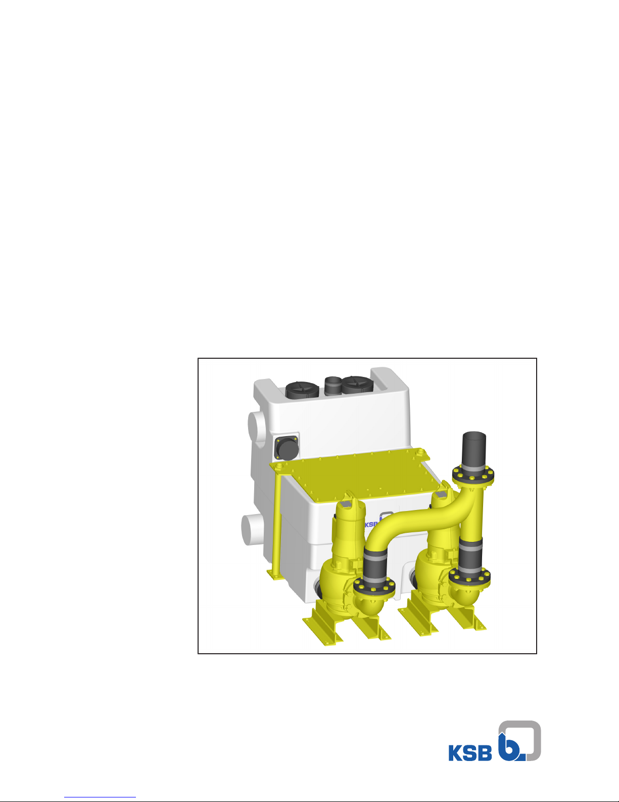
Sewage Lifting Unit
Compacta UZ, ZF, ZK
UZ - with Amarex N/KRT
ZF, ZK - with Sewabloc
From series S-V/1
From series 2013w01
Installation/Operating Manual
Page 2

Legal information/Copyright
Installation/Operating Manual Compacta UZ, ZF, ZK
Original operating manual
All rights reserved. The contents provided herein must neither be distributed, copied, reproduced,
edited or processed for any other purpose, nor otherwise transmitted, published or made available to a
third party without the manufacturer's express written consent.
Subject to technical modification without prior notice.
© KSB SE & Co. KGaA, Frankenthal 23/07/2018
Page 3

Contents
3 of 64
Compacta UZ, ZF, ZK
Contents
Glossary .................................................................................................................................................. 5
1 General.................................................................................................................................................... 6
1.1 Principles ...........................................................................................................................................................6
1.2 Installation of partly completed machinery....................................................................................................6
1.3 Target group.....................................................................................................................................................6
1.4 Other applicable documents............................................................................................................................6
1.5 Symbols .............................................................................................................................................................6
2 Safety...................................................................................................................................................... 7
2.1 Key to safety symbols/markings.......................................................................................................................7
2.2 General..............................................................................................................................................................7
2.3 Intended use .....................................................................................................................................................8
2.4 Personnel qualification and training...............................................................................................................8
2.5 Consequences and risks caused by non-compliance with this manual .........................................................8
2.6 Safety awareness ..............................................................................................................................................8
2.7 Safety instructions for the operator/user........................................................................................................9
2.8 Safety information for maintenance, inspection and installation ................................................................9
2.9 Unauthorised modes of operation..................................................................................................................9
3 Transport/Temporary Storage/Disposal............................................................................................. 10
3.1 Checking the condition upon delivery..........................................................................................................10
3.2 Transport.........................................................................................................................................................10
3.3 Storage/preservation......................................................................................................................................12
3.4 Return to supplier...........................................................................................................................................13
3.5 Disposal ...........................................................................................................................................................13
4 Description............................................................................................................................................ 14
4.1 General description ........................................................................................................................................14
4.2 Designation.....................................................................................................................................................14
4.3 Name plates ....................................................................................................................................................15
4.4 Design details..................................................................................................................................................15
4.5 Configuration and function...........................................................................................................................16
4.6 Technical data of the control unit.................................................................................................................18
4.6.1 Electrical data.....................................................................................................................................18
4.6.2 Technical specifications for sensors ..................................................................................................18
4.7 Fluids handled.................................................................................................................................................19
4.8 Collecting tank................................................................................................................................................19
4.9 Noise characteristics .......................................................................................................................................20
4.10 Scope of supply...............................................................................................................................................20
4.11 Dimensions and weights ................................................................................................................................20
5 Installation at Site................................................................................................................................ 21
5.1 Safety regulations...........................................................................................................................................21
5.2 Checks to be carried out prior to installation...............................................................................................21
5.3 Installing the lifting unit................................................................................................................................22
5.3.1 Setting up the tank(s)........................................................................................................................22
5.3.2 Setting up the pump..........................................................................................................................22
5.4 Connecting the piping ...................................................................................................................................23
5.5 Cellar drainage ...............................................................................................................................................24
5.6 Connection to power supply..........................................................................................................................25
5.7 Checking the direction of rotation................................................................................................................26
6 Commissioning/Start-up/Shutdown................................................................................................... 27
6.1 Commissioning/Start-up.................................................................................................................................27
6.1.1 Prerequisites for commissioning/start-up .........................................................................................27
6.2 Operating limits..............................................................................................................................................27
Page 4

Contents
4 of 64
Compacta UZ, ZF, ZK
6.2.1 Operating limits per operating mode ..............................................................................................27
6.2.2 Supply voltage....................................................................................................................................28
6.3 Commissioning/start-up of control unit........................................................................................................28
6.3.1 Lifting unit with LevelControl Basic 2...............................................................................................29
6.4 Shutdown........................................................................................................................................................30
7 Operation.............................................................................................................................................. 32
7.1 Control panel..................................................................................................................................................32
7.1.1 Indicators............................................................................................................................................32
7.1.2 Display ................................................................................................................................................33
7.1.3 Navigation keys..................................................................................................................................33
7.2 Manual-0-automatic selector switch .............................................................................................................34
7.3 Control panel..................................................................................................................................................34
7.3.1 Displaying measured value parameters............................................................................................34
7.3.2 Setting parameters ............................................................................................................................35
7.3.3 Acknowledging alerts and warnings ................................................................................................36
7.3.4 Displaying the alerts list ....................................................................................................................37
7.3.5 Replacing the rechargeable battery .................................................................................................37
8 Servicing/Maintenance........................................................................................................................ 38
8.1 General information/Safety regulations .......................................................................................................38
8.2 Servicing/inspection........................................................................................................................................38
8.2.1 Inspection contract ...........................................................................................................................39
8.2.2 Measuring the insulation resistance of the motor ..........................................................................39
8.2.3 Oil check/Oil change ..........................................................................................................................39
8.2.4 Emergency operation with one pump..............................................................................................39
8.3 Dismantling the pump ...................................................................................................................................40
8.4 Reassembly......................................................................................................................................................40
8.4.1 General instructions...........................................................................................................................40
8.4.2 Pump reassembly ...............................................................................................................................41
8.5 Tightening torques.........................................................................................................................................41
8.6 Disposal/recycling of the lifting unit .............................................................................................................41
8.7 Checklist for commissioning/inspection ➀ and maintenance ➁ ..................................................................41
9 Trouble-shooting.................................................................................................................................. 43
10 Related Documents.............................................................................................................................. 45
10.1 General assembly drawing/exploded view and list of components............................................................45
10.1.1 General assembly drawing of the lifting unit ..................................................................................45
10.1.2 Exploded view of collecting tank......................................................................................................47
10.2 Connection examples .....................................................................................................................................48
10.2.1 Compacta UZ10.450 - UZ15.450 ........................................................................................................48
10.2.2 Compacta UZ10.900 - UZ15.900 ........................................................................................................49
10.2.3 Compacta UZ20.450 - ZK56.450 ........................................................................................................50
10.2.4 Compacta UZ20.900 - ZK56.900 ........................................................................................................50
10.3 Dimensions......................................................................................................................................................52
10.4 Wiring diagrams .............................................................................................................................................53
10.4.1 LevelControl Basic 2 Type BC - dual-pump unit - DOL starting - up to 4kW - with motor
protection switch - for Compacta UZ................................................................................................53
10.4.2 LevelControl Basic 2 Type BS - dual-pump unit - DOL starting - 5.5kW and above - with motor
protection switch - for Compacta UZ................................................................................................54
10.4.3 LevelControl Basic 2 Type BS - dual-pump unit - star/delta starting - 5.5kW and above - with
motor protection switch - for Compacta UZ ....................................................................................55
10.4.4 LevelControl Basic 2 Type BS - for Compacta ZF and Compacta ZK................................................56
11 EU Declaration of Conformity............................................................................................................. 57
12 Declaration of Performance as per Regulation (EU) No. 305/2011, Annex III.................................. 58
13 Certificate of Decontamination........................................................................................................... 59
Index ..................................................................................................................................................... 60
Page 5

Glossary
5 of 64
Compacta UZ, ZF, ZK
Glossary
Certificate of decontamination
A certificate of decontamination is enclosed by the
customer when returning the product to the
manufacturer to certify that the product has been
properly drained to eliminate any environmental
and health hazards arising from components in
contact with the fluid handled.
DIN1986-3 and -30
German standard which stipulates technical rules
for the operation, maintenance and servicing of
drainage systems in buildings and on premises
Discharge line
Pipe for transporting waste water to a level above
the flood level into the sewer system
DOL starting
For low power ratings (usually up to 4kW), the
three-phase motor is connected directly to the
mains voltage.
Effective volume
Volume in the collection tank between start and
stop level that can be lifted
EN 12 056-4
European standard governing the selection,
operation and maintenance of sewage lifting units
within buildings and sites.
Flood level
Maximum backflow level of waste water in a
drainage system
Inlet line
Pipe used for draining waste water from sanitary
installations into the lifting unit
Nominal diameter DN
Identifier (inside diameter) used for characterising
mating components such as pipes, pipe
connections and fittings
Separator
Device for physically separating the two phases of
a two-phase flow, e.g. for separating solid
particles or liquid drops from flowing gases.
Sewage lifting unit
Device for collecting and automatically lifting
waste water with or without faeces above the
flood level
Stormwater
Water from natural precipitation which has not
been contaminated by any form of use
Vent line
Pipe provided to limit pressure fluctuations within
the sewage lifting unit. The vent line is led
through the roof.
Waste water
Water which has been changed by some type of
use, e.g. domestic waste water
Working space
The space required for performing work on the
unit
Page 6
1 General
6 of 64
Compacta UZ, ZF, ZK
1 General
1.1 Principles
This operating manual is valid for the type series and variants indicated on the front
cover.
The manual describes the proper and safe use of this equipment in all phases of
operation.
The name plate indicates the type series, the main operating data and the serial
number. The serial number uniquely describes the product and is used as
identification in all further business processes.
In the event of damage, immediately contact your nearest KSB Service centre to
maintain the right to claim under warranty.
1.2 Installation of partly completed machinery
To install partly completed machinery supplied by KSB refer to the sub-sections under
Servicing/Maintenance.
1.3 Target group
This operating manual is aimed at the target group of trained and qualified specialist
technical personnel.
1.4 Other applicable documents
Table1: Overview of other applicable documents
Document Contents
Sub-supplier product literature Operating manuals and other product literature
of accessories and integrated machinery
components,
operating manual of waste water pump
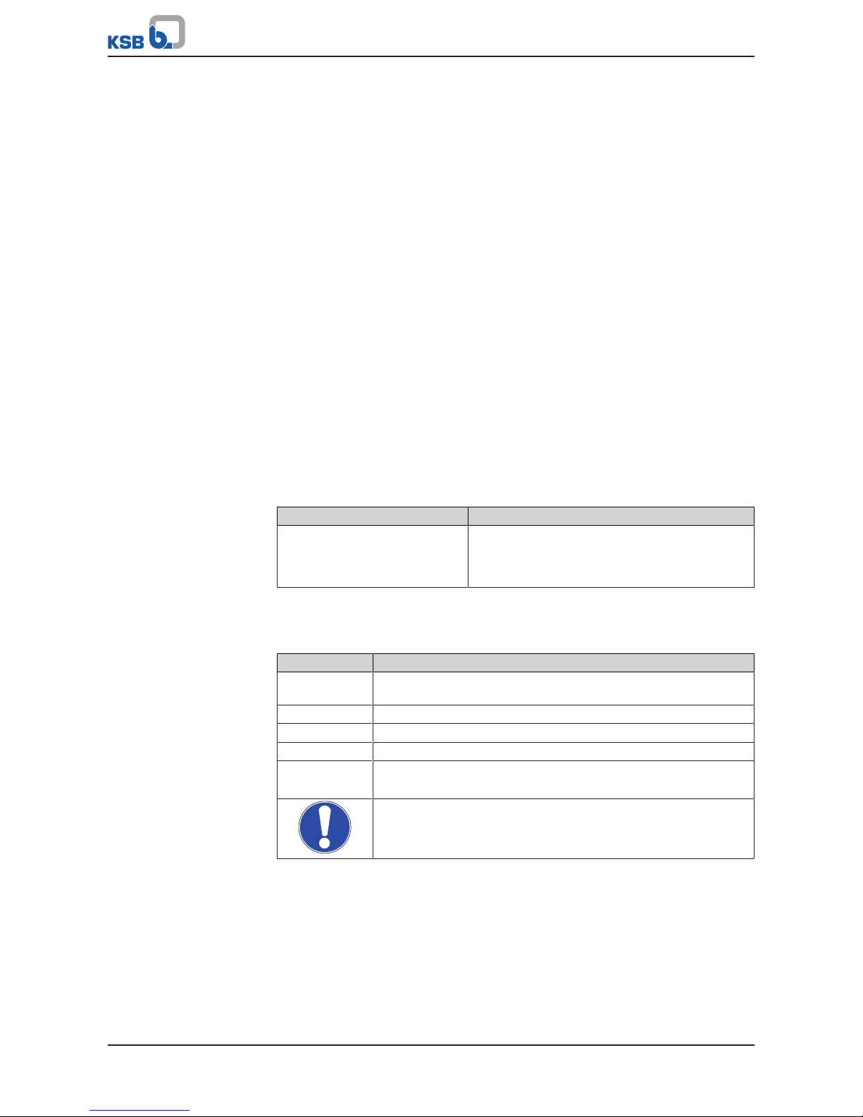
1.5 Symbols
Table2: Symbols used in this manual
Symbol Description
✓ Conditions which need to be fulfilled before proceeding with the
step-by-step instructions
⊳ Safety instructions
⇨
Result of an action
⇨ Cross-references
1.
2.
Step-by-step instructions
Note
Recommendations and important information on how to handle
the product
Page 7
2 Safety
7 of 64
Compacta UZ, ZF, ZK
2 Safety
!
DANGER
All the information contained in this section refers to hazardous situations.
In addition to the present general safety information the action-related safety
information given in the other sections must be observed.
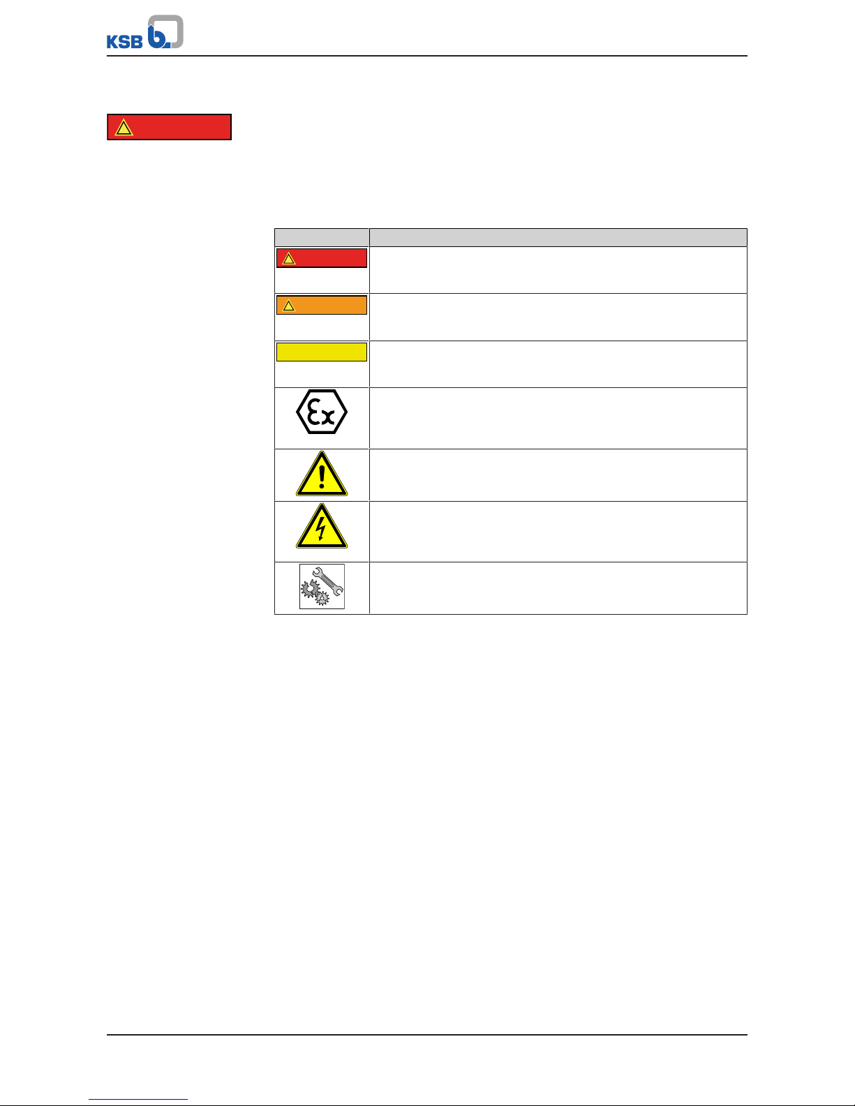
2.1 Key to safety symbols/markings
Table3: Definition of safety symbols/markings
Symbol Description
!
DANGER
DANGER
This signal word indicates a high-risk hazard which, if not avoided,
will result in death or serious injury.
!
WARNING
WARNING
This signal word indicates a medium-risk hazard which, if not
avoided, could result in death or serious injury.
CAUTION
CAUTION
This signal word indicates a hazard which, if not avoided, could
result in damage to the machine and its functions.
Explosion protection
This symbol identifies information about avoiding explosions in
potentially explosive atmospheres in accordance with EU Directive
2014/34/EU (ATEX).
General hazard
In conjunction with one of the signal words this symbol indicates a
hazard which will or could result in death or serious injury.
Electrical hazard
In conjunction with one of the signal words this symbol indicates a
hazard involving electrical voltage and identifies information about
protection against electrical voltage.
Machine damage
In conjunction with the signal word CAUTION this symbol indicates
a hazard for the machine and its functions.
2.2 General
This operating manual contains general installation, operating and maintenance
instructions that must be observed to ensure safe operation of the system and
prevent personal injury and damage to property.
The safety information in all sections of this manual must be complied with.
The operating manual must be read and understood by the responsible specialist
personnel/operators prior to installation and commissioning.
The contents of this operating manual must be available to the specialist personnel
at the site at all times.
Information attached directly to the product must always be complied with and kept
in a perfectly legible condition at all times. This applies to, for example:
▪ Arrow indicating the direction of rotation
▪ Markings for connections
▪ Name plate
The operator is responsible for ensuring compliance with all local regulations not
taken into account in this operating manual.
Page 8

2 Safety
8 of 64
Compacta UZ, ZF, ZK
2.3 Intended use
▪ The lifting unit must not be used in potentially explosive atmospheres.
▪ The lifting unit must only be operated within the operating limits described in
the other applicable documents.
▪ Only operate lifting units which are in perfect technical condition.
▪ Do not operate partially assembled lifting units.
▪ Only use the lifting unit to handle the fluids described in the product literature
of the respective design variant.
▪ Never operate the lifting unit without the fluid to be handled
▪ Observe the minimum flow rates indicated in the data sheet or product literature
(to prevent overheating, bearing damage, etc).
▪ Observe the minimum flow rate and maximum flow rate indicated in the data
sheet or product literature (to prevent overheating, mechanical seal damage,
cavitation damage, bearing damage, etc).
▪ Do not throttle the flow rate on the inlet side of the lifting unit (to prevent
cavitation damage)
▪ Consult the manufacturer about any use or mode of operation not described in
the data sheet or product literature.
▪ Never exceed the permissible application and operating limits specified in the
data sheet or product literature regarding pressure, temperature, etc.
▪ Observe all safety information and instructions in this manual.
2.4 Personnel qualification and training
All personnel involved must be fully qualified to install, operate, maintain and
inspect the equipment this manual refers to.
The responsibilities, competence and supervision of all personnel involved in
installation, operation, maintenance and inspection must be clearly defined by the
operator.
Deficits in knowledge must be rectified by means of training and instruction
provided by sufficiently trained specialist personnel. If required, the operator can
commission the manufacturer/supplier to train the personnel.
Training on the lifting unit must always be supervised by technical specialist
personnel.
2.5 Consequences and risks caused by non-compliance with this manual
▪ Non-compliance with these operating instructions will lead to forfeiture of
warranty cover and of any and all rights to claims for damages.
▪ Non-compliance can, for example, have the following consequences:
– Hazards to persons due to electrical, thermal, mechanical and chemical
effects and explosions
– Failure of important product functions
– Failure of prescribed maintenance and servicing practices
– Hazard to the environment due to leakage of hazardous substances
2.6 Safety awareness
In addition to the safety information contained in this manual and the intended use,
the following safety regulations shall be complied with:
▪ Accident prevention, health regulations and safety regulations
▪ Explosion protection regulations
▪ Safety regulations for handling hazardous substances
▪ Applicable standards, directives and laws
Page 9

2 Safety
9 of 64
Compacta UZ, ZF, ZK
2.7 Safety instructions for the operator/user
▪ Fit protective equipment (e.g. contact guards) supplied by the operator for hot,
cold or moving parts, and check that the equipment functions properly.
▪ Do not remove any protective equipment (e.g. contact guards) during operation.
▪ Provide the personnel with protective equipment and make sure it is used.
▪ Contain leakages (e.g. at the shaft seal) of hazardous fluids handled (e.g.
explosive, toxic, hot) so as to avoid any danger to persons and the environment.
Adhere to all relevant laws.
▪ Eliminate all electrical hazards. (In this respect refer to the applicable national
safety regulations and/or regulations issued by the local energy supply
companies.)
2.8 Safety information for maintenance, inspection and installation
▪ Modifications or alterations of the lifting unit require the manufacturer's prior
consent.
▪ Use only original spare parts or parts authorised by the manufacturer. The use of
other parts can invalidate any liability of the manufacturer for resulting damage.
▪ The operator ensures that maintenance, inspection and installation is performed
by authorised, qualified specialist personnel who are thoroughly familiar with
the manual.
▪ Carry out work on the lifting unit during standstill only.
▪ The pump casing must have cooled down to ambient temperature.
▪ Pump pressure must have been released and the pump must have been drained.
▪ When taking the lifting unit out of service always adhere to the procedure
described in the manual.
▪ Decontaminate lifting units which handle fluids posing a health hazard.
(ðSection8.1,Page38)
▪ As soon as the work has been completed, re-install and re-activate any safety-
relevant devices and protective devices. Before returning the product to service,
observe all instructions on commissioning.
▪ Make sure the lifting unit cannot be accessed by unauthorised persons (e.g.
children).
2.9 Unauthorised modes of operation
Always observe the limits stated in the product literature.
The warranty relating to the operating reliability and safety of the lifting unit
supplied is only valid if the equipment is used in accordance with its intended use.
(ðSection2.3,Page8)
Page 10
3 Transport/Temporary Storage/Disposal
10 of 64
Compacta UZ, ZF, ZK
3 Transport/Temporary Storage/Disposal
3.1 Checking the condition upon delivery
1. On transfer of goods, check each packaging unit for damage.
2. In the event of in-transit damage, assess the exact damage, document it and
notify KSB or the supplying dealer and the insurer about the damage in writing
immediately.
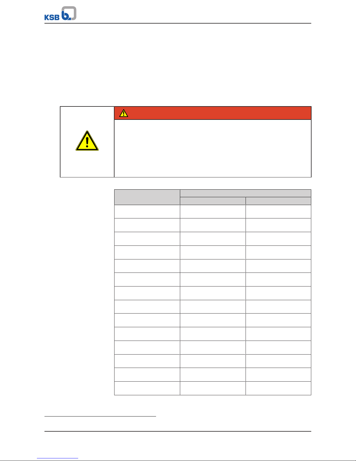
3.2 Transport
DANGER
Lifting unit falling off the pallet
Risk of injury from falling lifting unit!
▷ Always transport the lifting unit in a horizontal position.
▷ Give due attention to the weight data, centre of gravity and fastening points.
▷ Never suspend the lifting unit by its power cable.
▷ Use suitable and permitted transport equipment, e.g. crane, forklift or pallet
truck.
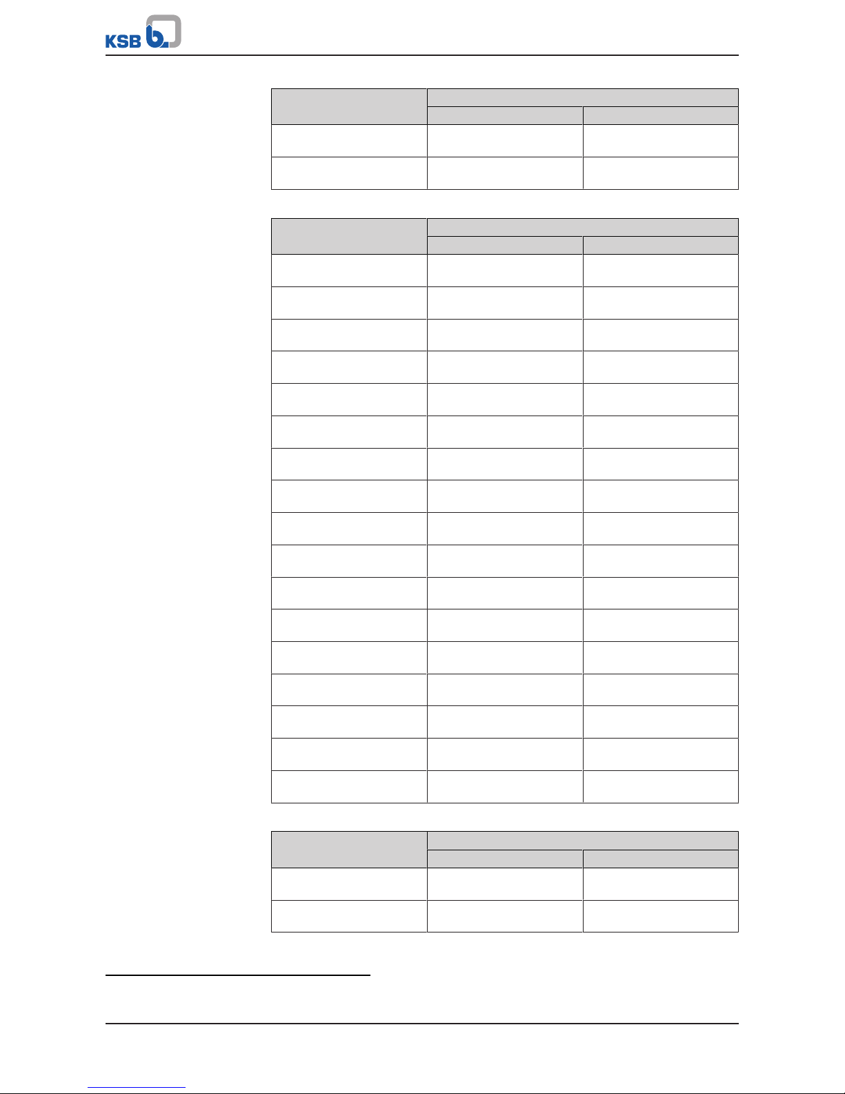
Table4: Weight Compacta UZ - Amarex N/KRT [kg]
Sizes Weight
Per pump Lifting unit
1)
UZ10.450D
UZ10.900D
85
85
305
380
UZ11.450D
UZ11.900D
87
87
315
390
UZ12.450D
UZ12.900D
142
142
400
485
UZ13.450D
UZ13.900D
153
153
420
505
UZ14.450D
UZ14.900D
180
180
470
555
UZ15.450D
UZ15.900D
180
180
470
555
UZ20.450D
UZ20.900D
165
165
465
540
UZ21.450D
UZ21.900D
175
175
485
560
UZ22.450D
UZ22.900D
213
213
561
646
UZ23.450D
UZ23.900D
213
213
564
646
UZ24.450D
UZ24.900D
213
213
561
646
UZ25.450D
UZ25.900D
213
213
561
646
UZ26.450D
UZ26.900D
213
213
561
646
UZ27.450D
UZ27.900D
180
180
495
570
1) Weight of the lifting unit without water fill
Page 11
3 Transport/Temporary Storage/Disposal
11 of 64
Compacta UZ, ZF, ZK
Sizes Weight
Per pump Lifting unit
1)
UZ28.450D
UZ28.900D
180
180
495
570
UZ29.450D
UZ29.900D
180
180
495
570
Table5: Weight Compacta ZF - Sewabloc [kg]
Sizes Weight
Per pump Lifting unit
2)
ZF30.450D
ZF30.900D
195
195
525
600
ZF31.450D
ZF31.900D
204
204
543
618
ZF32.450D
ZF32.900D
204
204
543
618
ZF33.450D
ZF33.900D
275
275
695
770
ZF34.450D
ZF34.900D
335
335
695
770
ZF35.450D
ZF35.900D
335
335
695
770
ZF36.450D
ZF36.900D
335
335
695
770
ZF40.450D
ZF40.900D
117
117
369
444
ZF41.450D
ZF41.900D
121
121
377
452
ZF42.450D
ZF42.900D
134
134
403
478
ZF43.450D
ZF43.900D
141
141
417
492
ZF44.450D
ZF44.900D
141
141
417
492
ZF45.450D
ZF45.900D
170
170
475
550
ZF46.450D
ZF46.900D
182
182
499
574
ZF47.450D
ZF47.900D
121
121
377
452
ZF48.450D
ZF48.900D
130
130
395
470
ZF49.450D
ZF49.900D
135
135
405
480
Table6: Weight Compacta ZK - Sewabloc [kg]
Sizes Weight
Per pump Lifting unit
3)
ZK50.450D
ZK50.900D
128
128
391
466
ZK51.450D
ZK51.900D
128
128
391
466
2) Weight of the lifting unit without water fill
3) Weight of the lifting unit without water fill
Page 12
3 Transport/Temporary Storage/Disposal
12 of 64
Compacta UZ, ZF, ZK
Sizes Weight
Per pump Lifting unit
3)
ZK52.450D
ZK52.900D
135
135
405
480
ZK53.450D
ZK53.900D
135
135
405
480
ZK54.450D
ZK54.900D
135
135
405
480
ZK55.450D
ZK55.900D
141
141
417
492
ZK56.450D
ZK56.900D
141
141
417
492
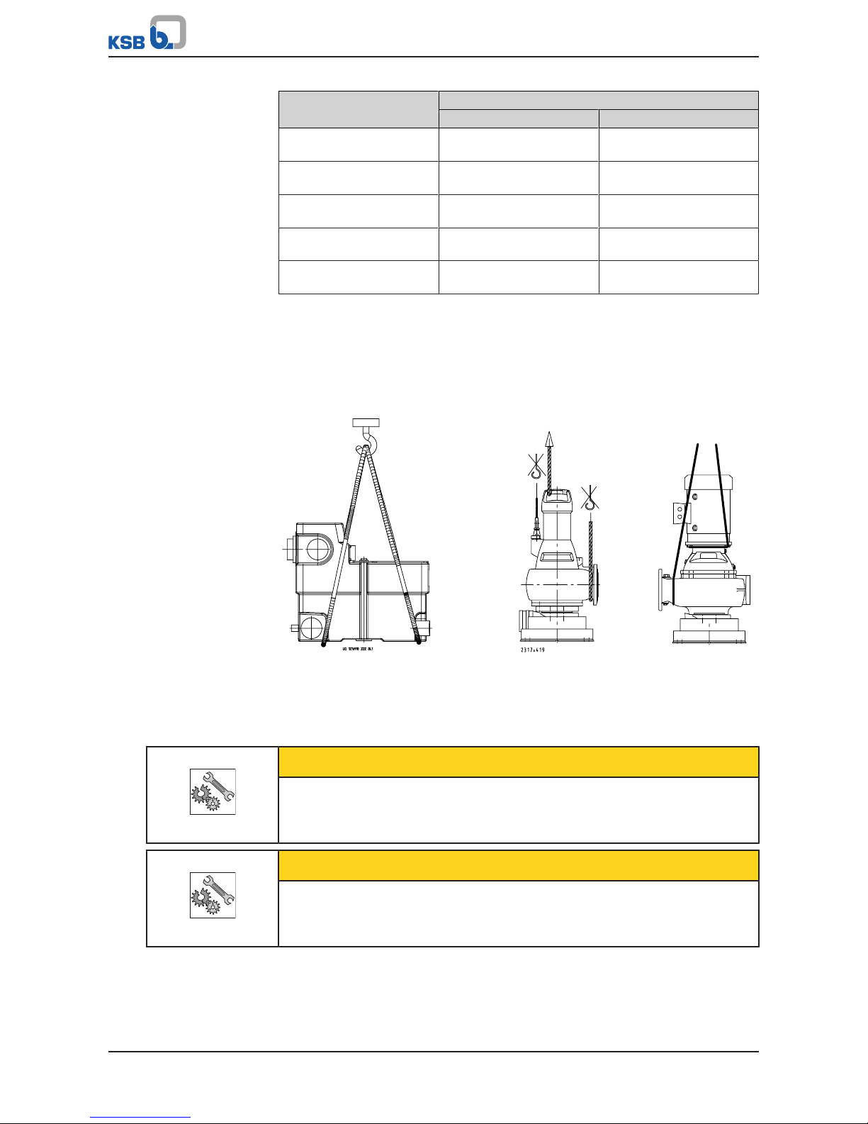
ü The lifting unit has been checked for in-transit damage.
1. Select suitable transport equipment (in acc. with weights table).
2. Transport the tank/pump to the place of installation.
3. Remove the transport fixtures.
4. Use suitable lifting equipment to place the tank/pump down at the place of
installation (as shown).
Fig.1: Transporting the tank - Amarex/KRT - Sewabloc
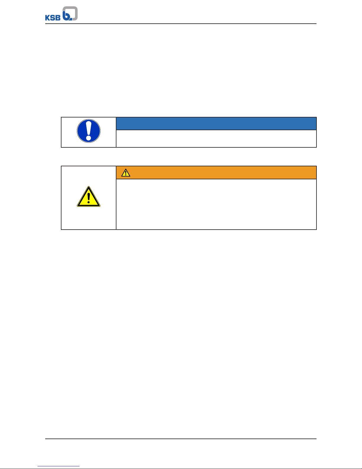
3.3 Storage/preservation
If commissioning is to take place some time after delivery, we recommend that the
following measures be taken for storing the lifting unit:
CAUTION
Damage during storage due to frost, humidity, dirt, UV radiation or vermin
Corrosion/contamination of the lifting unit!
▷ Store the lifting unit in a frost-proof, roofed area.
CAUTION
Wet, contaminated or damaged openings and connections
Leakage or damage of the lifting unit!
▷ Only open the openings of the lifting unit at the time of installation.
Store the lifting unit in a dry, protected room where the atmospheric humidity is as
constant as possible.
Page 13
3 Transport/Temporary Storage/Disposal
13 of 64
Compacta UZ, ZF, ZK
3.4 Return to supplier
1. Drain the lifting unit as described in the manual.
2. Always flush and clean the lifting unit, particularly if it has been used for
handling noxious, explosive, hot or other hazardous fluids.
3. If the unit has handled fluids whose residues could lead to corrosion damage in
the presence of atmospheric humidity or could ignite upon contact with oxygen,
the unit must also be neutralised and blown through with anhydrous inert gas
to ensure drying.
4. Always complete and enclose a certificate of decontamination when returning
the lifting unit. (ðSection13,Page59)
Always indicate any safety and decontamination measures taken.
NOTE
If required, a blank certificate of decontamination can be downloaded from the
following web site: www.ksb.com/certificate_of_decontamination
3.5 Disposal
WARNING
Fluids handled, consumables and supplies which are hot and/or pose a health
hazard
Hazard to persons and the environment!
▷ Collect and properly dispose of flushing fluid and any fluid residues.
▷ Wear safety clothing and a protective mask if required.
▷ Observe all legal regulations on the disposal of fluids posing a health hazard.
1. Dismantle the lifting unit.
Collect greases and other lubricants during dismantling.
2. Separate and sort the pump materials, e.g. by:
- Metals
- Plastics
- Electronic waste
- Greases and other lubricants
3. Dispose of materials in accordance with local regulations or in another
controlled manner.
Page 14

4 Description
14 of 64
Compacta UZ, ZF, ZK
4 Description
4.1 General description
Floodable sewage lifting unit
▪ The sewage lifting unit consists of either one or two collecting tanks, two pump
sets and the unit control system.
NOTE
The flow velocity in the discharge line must not be less than 0.7m/s and not higher
than 2.3 m/s.
NOTE
The effective volume of the lifting unit must be greater than the volumetric
content of the discharge line up to the backflow loop.
4.2 Designation
Example: Compacta UZ X 12.450 D
Table7: Designation key
Code Description
Compacta Type series
UZ Type of lifting unit
U Floodable AmarexKRT submersible motor pump,
Fimpeller
Z Dual-pump unit
F Dry-installed Sewabloc volute casing pump,
Fimpeller
K Dry-installed Sewabloc volute casing pump,
Kimpeller
X Special design
12 Hydraulics code
450 Total volume of collecting tank [litres]
450,
900
D Three-phase motor
Control unit
Example: BC 2 400 D V N A 100 B 2
Table8: Designation key
Code Description
BC Type
BC Basic Compact
2 Number of pumps
400 Electrical voltage, e.g. 400V, resulting in the number of
wires (e.g. 400V, 4wires or 5wires)
D Starting method
D DOL starting
V Sensor 0-5V
N Without ATEX function
A Installation option with rechargeable battery
100 Rated current x 10 (e.g. 10A)
Page 15
4 Description
15 of 64
Compacta UZ, ZF, ZK
Code Description
B Pump variant
2 Country-specific version
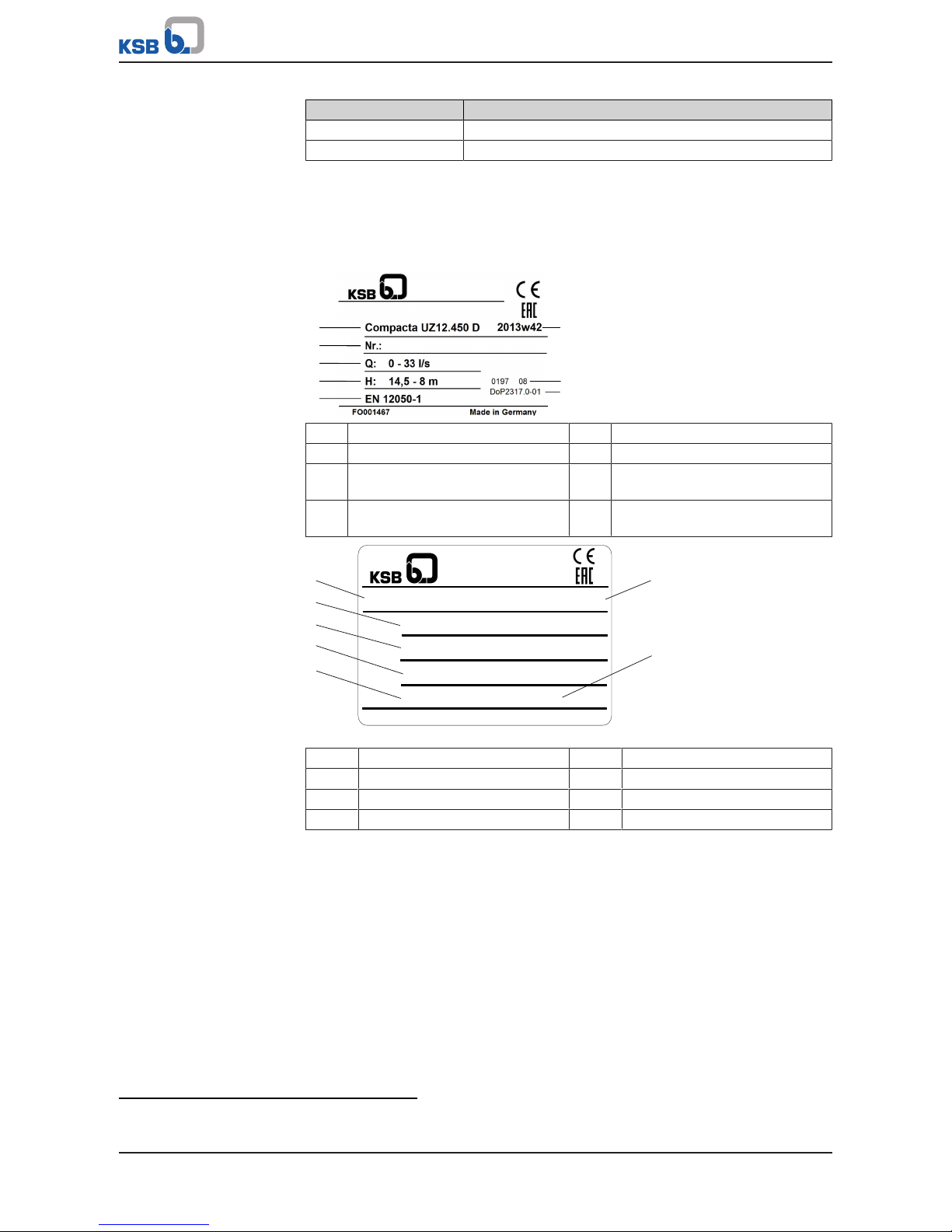
4.3 Name plates
Examples:
Pump For the pump name plate refer to the installation/operating manual of the waste
water pump.
Tank
1
2
3
4
5
6
7
8
Johann-Klein-Straße 9
Deutschland
67227 Frankenthal
KSB SE & Co. KGaA
1 Type series, size 2 Serial No.
3 Maximum flow rate 4 Maximum head
5 Principles of construction and
testing
6 Year/week of construction
7 Notified body / year of
introduction
8 Declaration of performance
reference No.
Control unit
1
2
3
4
5
6
7
ZNI 1448xa
2014w07
BD706005
BC2400DFNO100
IP 54
Made in Germany
Ue: 3/N/PE/AC 400 V 50 HZ
Ie: 6,3 - 10,0 A
LevelControl Basic 2
Johann-Klein-Straße 9
Deutschland
67227 Frankenthal
KSB SE & Co. KGaA
Fig.2: Example of name plate
1 Designation 2 Product code
3 Nominal voltage 4 Nominal current
5 Circuit diagram number 6 Year/week of construction
7 Enclosure
4.4 Design details
Lifting unit
Design
▪ Sewage lifting unit to EN12050-1
▪ Ready-to-connect dual-pump station
▪ Gas and water-proof plastic collecting tank, sensors and control unit
– UZ, ZF, ZK900 battery design with two collecting tanks
Compacta UZ:
▪ Floodable sewage lifting unit
4)
▪ Two vertically installed submersible waste water pumps
4) Max. flooding height: 2 metres, max. flooding period: 7 days (does not apply to control unit). The lifting unit must be
cleaned and serviced after it has been flooded.
Page 16
4 Description
16 of 64
Compacta UZ, ZF, ZK
Compacta ZF, ZK:
▪ Two dry-installed vertical waste water volute casing pumps
Drive
▪ Surface-cooled
▪ Three-phase motor
▪ Thermal class F
▪ Electrical voltage 400V (three-phase motor)
▪ Frequency 50 Hz
▪ DOL starting (from 5.5kW star-delta starting)
Compacta UZ:
▪ Submersible motor made by KSB, IP68 enclosure
▪ Monitoring by temperature switches in the winding
Compacta ZF, ZK:
▪ Standardised motor made by KSB, IP55 enclosure
▪ Monitoring via three PTC thermistors
Impeller type
▪ Free-flow impeller
▪ Various application-oriented impeller types
Bearings
▪ Grease-packed, maintenance-free rolling element bearings
Shaft seal
▪ Two bi-directional mechanical seals with oil reservoir filled with environmentally
friendly oil
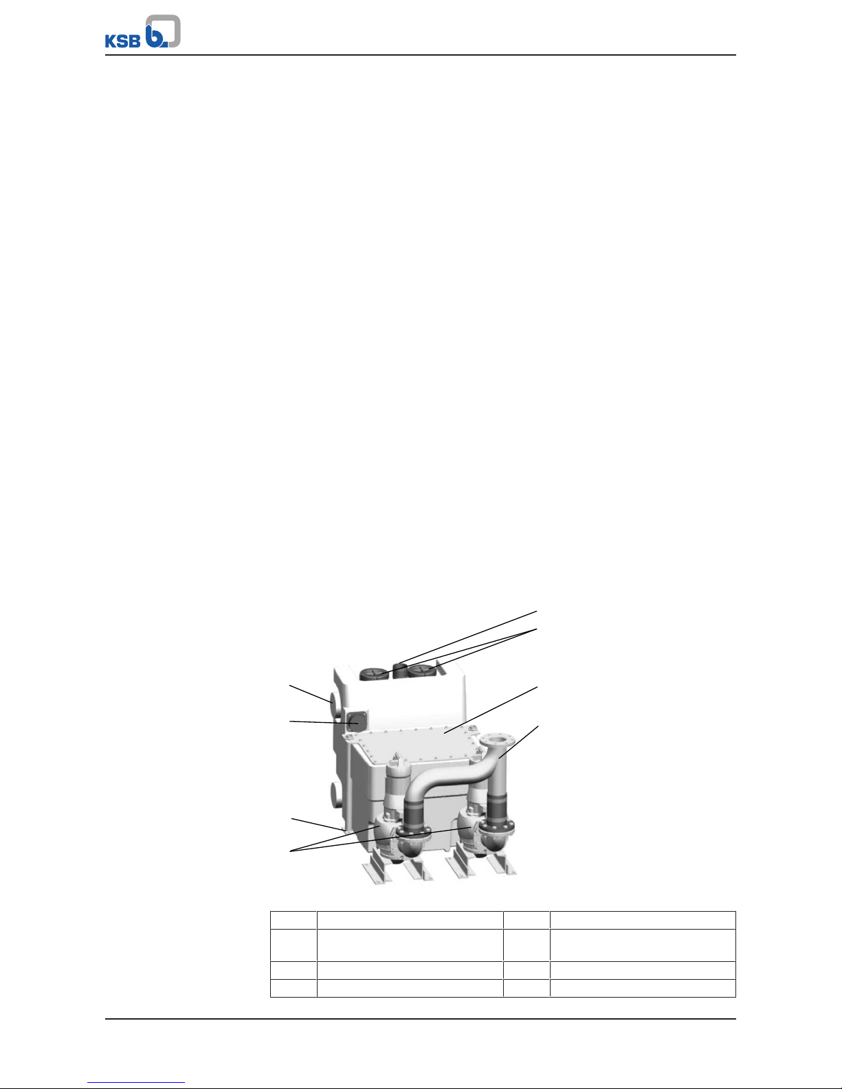
4.5 Configuration and function
1
3
7
8
2
4
6
5
Fig.3: Compacta
1 Inlet 2 Level sensor
3 Transport and
float protection
4 Pump
5 Vent connection 6 Hand hole cover
7 Tank 8 Discharge line
Page 17
4 Description
17 of 64
Compacta UZ, ZF, ZK
Design The lifting unit is provided with several horizontal inlet nozzles(1). The pump(4)
pumps the fluid handled into the vertical discharge line(8).
Function The fluid to be handled flows into the lifting unit through horizontal inlet nozzles(1)
and is collected in a gas-, odour- and water-tight plastic tank(7). When the level
sensor detects a defined fill level, the fluid is automatically pumped off to a level
above the flood level and towards the public sewer by either one or two pumps(4).
Sealing Two bi-directional mechanical seals supplied with environmentally-friendly oil.
Control unit
DANGER
Flooding of control unit
Danger of death from electric shock!
▷ Operate the control unit in flood-proof rooms only.
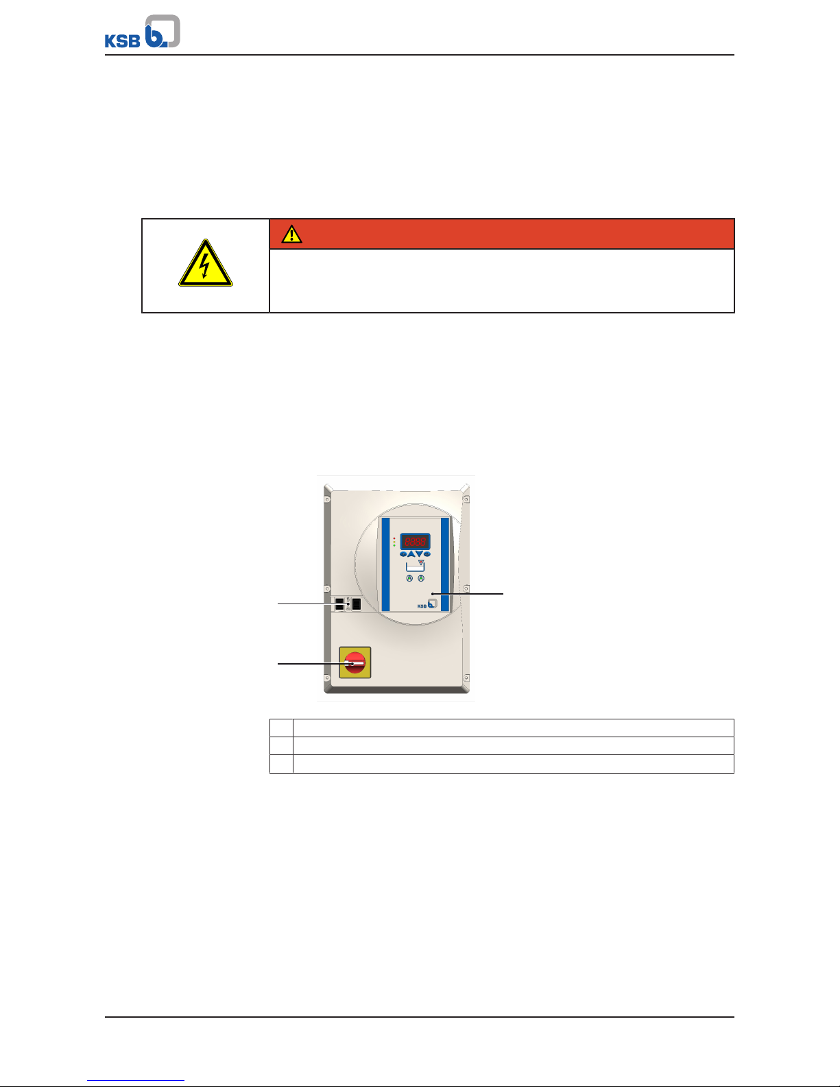
LevelControl Basic 2
Type BasicCompact (BC)
▪ Pump control and monitoring unit in compact plastic housing
▪ For either one or two pumps
▪ With display
▪ Level detection via:
– Level sensor 0-5V
▪ DOL starting
2
3
1
Fig.4: Type Basic Compact (BC)
1 Control panel
2 Master switch (optional)
3 Manual-0-automatic switch
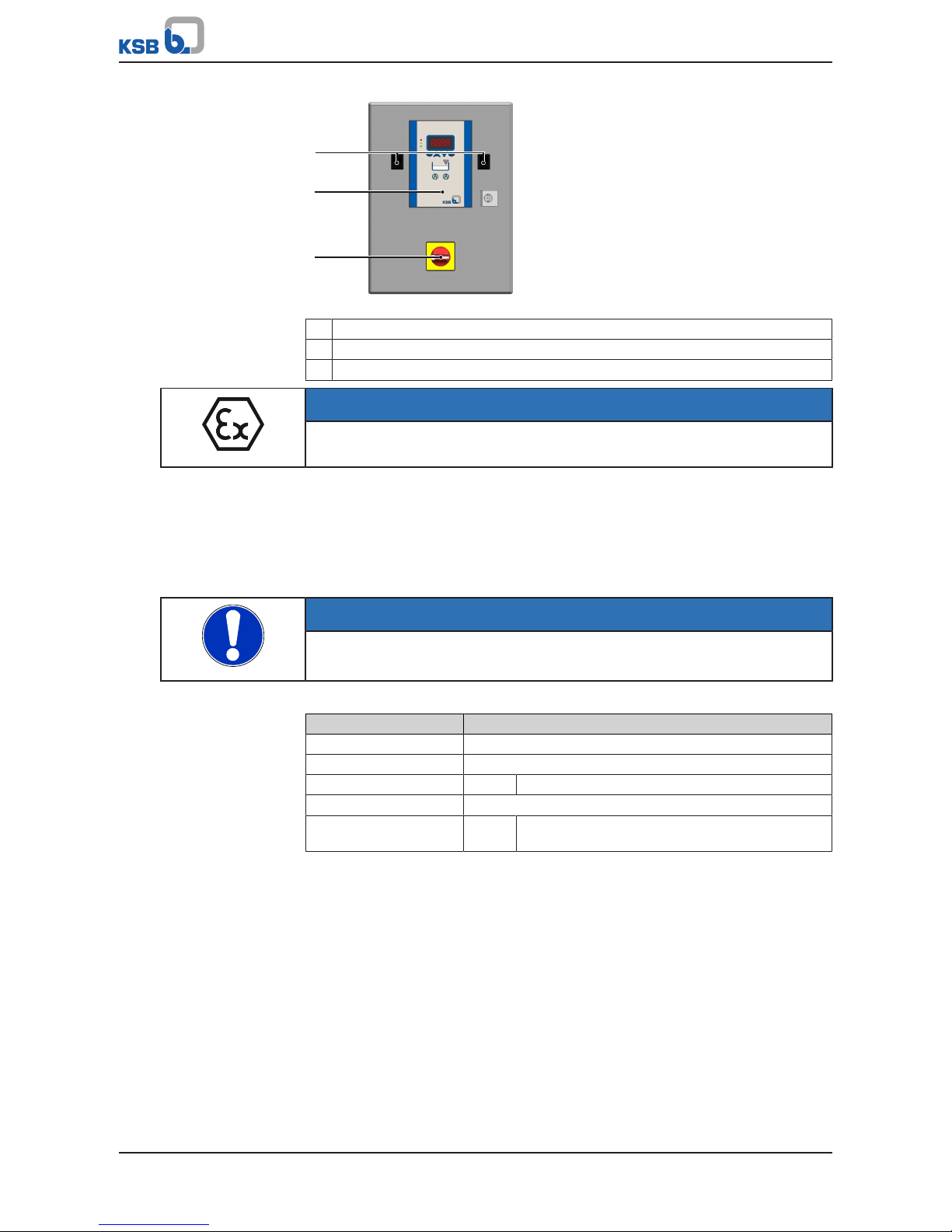
LevelControl Basic 2
Type Basic Control Cabinet (BS)
▪ Pump control and monitoring unit in sheet steel housing
▪ For either one or two pumps
▪ With display
▪ Level detection via:
– Level sensor 0-5V
▪ DOL starting or star/delta starting
Page 18
4 Description
18 of 64
Compacta UZ, ZF, ZK
1
2
3
Fig.5: Type Basic Control Cabinet (BS)
1 Master switch
2 Control panel
3 Manual-0-automatic switch
NOTE
The control units are not explosion-proof, and therefore must only be operated
outside potentially explosive atmospheres.
The control unit is always located outside the potentially explosive atmosphere and
may only be installed in a flood-proof room.
4.6 Technical data of the control unit
4.6.1 Electrical data
NOTE
The rated current must not be exceeded.
Higher currents and power ratings are available on request.
Table9: Electrical data of the LevelControl Basic 2 control unit
Characteristic Value
Rated operating voltage 3 ~ 400 V AC +10 % -15 %
Mains frequency 50 Hz ± 2%
Enclosure 400V: IP54
Rated insulation voltage 500V AC
Rated current per motor
(standard models)
Type
BS:
1.6A / 2.5A / 4A / 6.3A / 10A / 14A / 18A / 23A /
25A / 40A / 63A
4.6.2 Technical specifications for sensors
Analog level sensor
▪ Input voltage 0-5V
Motor protection sensors
▪ Max. 2 bimetal switches (thermal circuit breaker) for each pump, 24V, motor
monitoring, PTC data analysis for Compacta ZF, ZK
▪ Max. 1 moisture monitor for each Amarex N/KRT pump
Process inputs
▪ 1 x external alarm input, 24V, via volt-free contact
▪ 1 x remote acknowledgement, 24V, via volt-free contact
Page 19
4 Description
19 of 64
Compacta UZ, ZF, ZK
Process outputs
▪ 1 x volt-free signalling output (250V, 1A, changeover contact)
▪ 1 x signalling output (12.6 to 13.2V), e.g. for connecting a horn, alarm
combination or alarm strobe light (12V connection)
Rechargeable battery
Connection for rechargeable battery, for mains-independent power supply of:
▪ Electronics
▪ Sensors
▪ Alarm equipment
Battery life/charging time
Battery life:
▪ Approx. 10 hours when supplying the integrated piezo buzzer 85dB(A),
electronics, and sensors
▪ Approx. 4 hours when supplying external alarm equipment (e.g. horn, alarm
combination, or alarm strobe light)
Charging time
▪ Approx. 11 hours (if battery is fully discharged)
4.7 Fluids handled
WARNING
Pumping of impermissible fluids
Hazardous to persons and the environment!
▷ Only discharge permissible fluids into the public sewer system.
▷ Check the suitability of pump/system materials.
Permissible
fluids
According to DIN1986-3 the following fluids can be discharged into sewer systems:
Water contaminated by domestic use, human and - as far as required and permitted animal faeces together with the necessary flushing water as well as stormwater in
case no other way of disposal is possible.
5)
Impermissible
fluids
Substances / water which must not be discharged into the sewer system are, amongst
others:
Solid matter, fibres, tar, sand, cement, ash, coarse paper, paper towels, cardboard,
debris, garbage, offal, grease, oil.
Waste water from installations situated above the flood level (EN12056-1).
Waste water containing hazardous substances (DIN1986-100), e.g. greasy waste
water from large-scale catering kitchens.
For drainage of greasy water a grease separator to DIN4040-1 must be fitted.
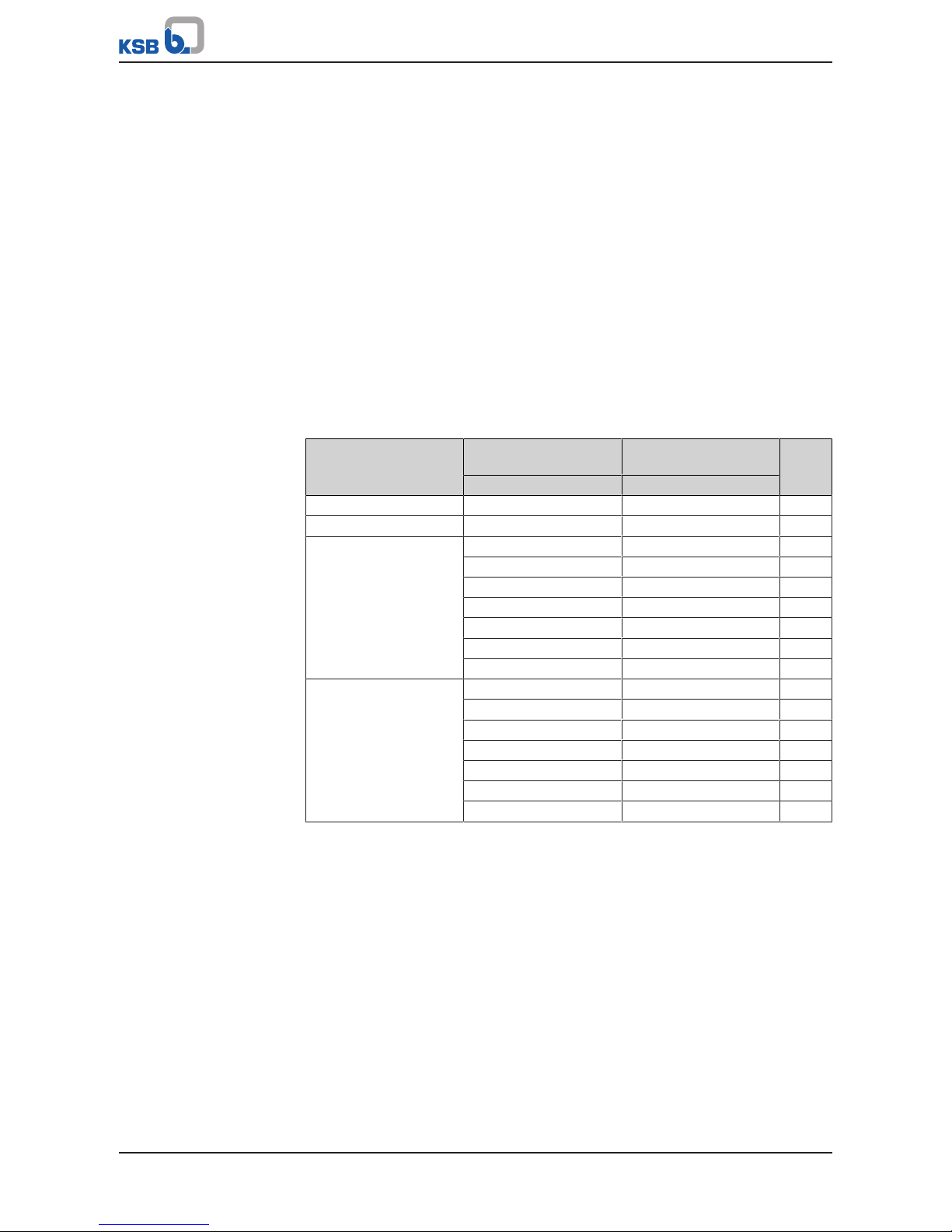
4.8 Collecting tank
The collecting tank is designed for unpressurised operation; that means the waste
water is stored in the tank in unpressurised condition and is then pumped into the
sewer system.
Size Total volume
Effective volume
Litres Litres
UZ450 450 290
UZ900 900 580
5) Other types of waste water, e.g. industrial waste water, must not be discharged into the local sewer system without prior
treatment.
Page 20
4 Description
20 of 64
Compacta UZ, ZF, ZK
4.9 Noise characteristics
The sound pressure level depends on the local conditions and the duty point. It is
≤70dB(A).
4.10 Scope of supply
Depending on the model, the following items are included in the scope of supply:
Sewage lifting unit consisting of:
▪ Either one or two gas-, odour- and water-tight collecting tanks made of impact-
resistant plastic material, with two waste water pumps
▪ Flexible hose connections and hose clips
▪ Automatic level transmitter
▪ Electronic control unit
4.11 Dimensions and weights
available For dimensions and weights please refer to the outline drawing of the lifting unit.
Control unit Table10: Dimensions and weights
LevelControl Maximum current Size
H × B × T
[kg]
[A] [mm]
Basic 1 10 135 × 171 × 107 3
Basic 2 BC 10 400 × 281 × 135 3
Basic 2 BS1 10 400 × 300 × 155 10
14 600 × 400 × 200 14
18 600 × 400 × 200 14
23 600 × 400 × 200 14
25 600 × 400 × 200 14
40 800 × 600 × 200 18
63 800 × 600 × 200 18
Basic 2 BS2 10 400 × 300 × 155 16
14 800 × 600 × 200 19
18 800 × 600 × 200 19
23 800 × 600 × 200 19
25 800 × 600 × 200 19
40 800 × 600 × 200 24
63 800 × 600 × 200 26
Page 21

5 Installation at Site
21 of 64
Compacta UZ, ZF, ZK
5 Installation at Site
The "Installation at Site" section describes the conditions which must be fulfilled for
assembling the complete sewage lifting unit in accordance with the instructions and
without compromising the safety and health of persons.
5.1 Safety regulations
DANGER
Improper installation
Explosion hazard!
▷ Never use sewage lifting units in potentially explosive atmospheres.
WARNING
Hot motor surface
Risk of injury!
▷ Allow the motor to cool down to ambient temperature.
CAUTION
Incorrect connection of the three-phase motor
Damage to the lifting unit!
▷ Always use a 3-pole mechanically interlocked K-type automatic circuit breaker
for external protection.
CAUTION
Incorrect installation of connections and signalling devices
A failure of the lifting unit can cause damage to property by flooding due to the
risk of backflow from the sewage system.
▷ Fit operator-supplied mains-independent alarm equipment (e.g. alarm
switchgear).
▷ Take suitable measures at the site to prevent overflow/flooding (e.g. a swing
check valve in the floor drain, or similar).
5.2 Checks to be carried out prior to installation
Place of installation
WARNING
Installation on mounting surfaces which are unsecured and cannot support the
load
Personal injury and damage to property!
▷ Use a concrete of compressive strength class C12/15 which meets the
requirements of exposure class X0 to EN206-1.
▷ The mounting surface must have set and must be completely horizontal and
even.
▷ Observe the weights indicated.
Check structural requirements.
All structural work required must have been prepared in accordance with the
dimensions stated in the outline drawings/connection examples.
(ðSection10.2,Page48)
Page 22

5 Installation at Site
22 of 64
Compacta UZ, ZF, ZK
5.3 Installing the lifting unit
5.3.1 Setting up the tank(s)
NOTE
Lifting units should not be installed next to sleeping or living quarters.
WARNING
Insufficient ventilation
Personal injury and damage to property!
▷ Provide proper aeration and ventilation.
▷ For room drainage, a pump sump must be provided.
ü The name plate data has been compared against the purchase order and the site
data (e.g. supply voltage, frequency, pump operating data, etc).
ü The fluid to be handled is an approved fluid. (ðSection4.7,Page19)
ü The installation room is frost-proof.
ü All structural work required has been prepared in accordance with the
dimensions stated in the connection example and in EN12056.
ü The installation room is of sufficient size - see connection example.
(ðSection10.2,Page48)
ü The installation room is adequately lit.
ü Alarm messages are always recognised in time by the operator (use an external
alarm transmitter, if required).
1. Place the tank on a level floor and align with the help of a spirit level.
2. Place pads 99-3.2 under the foot areas of tank 591.
NOTE
The anti-vibration mounts of the lifting unit provide adequate insulation against
solid-borne noise.
3. Use the transport/float protection fixtures supplied to secure the tank firmly to
the floor.
Battery design with two collecting tanks UZ, ZF, ZK 900
Connect the two tanks with each other via the two DN150 connection nozzles (1x
connection level 100mm and 1x connection level 700mm), using flexible hose
connections.
5.3.2 Setting up the pump
1. Place pads 99-3.2 under the foot points of the pumps.
2. Connect the pump inlet to the collecting tank by means of the flexible
connection supplied (flexible tube 719.6 with internal pipe 710.2 and pipe clamps
733.21).
3. Align the pumps using a spirit level.
4. Fasten pump foot 182 to the foundation using screws and plug fixings 90-3.
NOTE
For the individual discharge pipes of the pumps to be connected to a common
discharge line via a Y-pipe, the distances between the pump centrelines given in the
installation examples must absolutely be complied with. (ðSection10.2,Page48)
Page 23

5 Installation at Site
23 of 64
Compacta UZ, ZF, ZK
NOTE
In battery design (two tanks), each pump is assigned to a tank.
5.4 Connecting the piping
DANGER
Impermissible loads acting on the system nozzles
Danger to life from leakage of hot, toxic, corrosive or flammable fluids!
▷ Do not use the lifting unit as an anchorage point for the piping.
▷ Anchor the pipes immediately upstream of the lifting unit and connect them
without transmitting any stresses or strains.
▷ Observe the permissible forces and moments at the lifting unit.
(ðSection8.5,Page41)
▷ Take appropriate measures to compensate thermal expansion of the piping.
NOTE
The installation of check and shut-off elements is mandatory. However, such
elements must not obstruct proper drainage or hinder disassembly of the lifting
unit.
Discharge line
CAUTION
Incorrect installation of discharge line
Leaks and flooding of installation room!
▷ Run the discharge line above the flood level before leading it into the sewer.
▷ Do not connect the discharge line to the downpipe.
▷ Do not connect any additional sanitary installations to the discharge line.
NOTE
To prevent any backflow from the collecting main, run the discharge line in the
form of a pipe loop whose invert at its highest point must be above the locally
defined flood level (e.g. street level).
A gate valve must be installed downstream of the check valve.
Inlet line
A gate valve must be fitted so that the inlet line can be shut off temporarily during
repair work or servicing.
Compacta units have variable inlet nozzle levels.
ü Piping weights have been supported at the site.
ü All tank nozzles are closed.
1. Determine which connection nozzles will be used.
2. Open the nozzles required (▼A) by sawing off the nozzle faces (approx.10mm).
Page 24

5 Installation at Site
24 of 64
Compacta UZ, ZF, ZK
A
A
Fig.6: Opening the nozzles
Vent line
for the collecting tank
Sewage lifting units to EN12050-1 must be vented through the roof.
The vent line must not be connected to the inlet-side vent line of a grease separator.
Connect the DN70 vent line to the vertical vent nozzle by means of the flexible hose
connection, making sure that the connection is odour-proof.
If changes of direction are unavoidable, the pipe should be laid with a minimum
gradient of 1:50.
NOTE
Lifting units featuring two collecting tanks require just one vent line.
Pump vent lines
Vent lines 70-1 must be fitted between the collecting tank and connection elbow
72-1.1 of each pump. (ðSection10.1.1,Page45)
The parts required are included in the scope of supply.
CAUTION
Air collecting in the upper section of the pump casing (on UZ10.450 to UZ11.900)
Specified performance data are not achieved!
▷ Connect the vent line directly to the pump casing (see B5.1 in general assembly
drawing). (ðSection10.1.1,Page45)
Drainage nozzle for hand diaphragm pump
NOTE
We recommend connecting a hand diaphragm pump (available as accessory) to
allow complete drainage of the tank for servicing work.
Fit this pump, using the flexible hose connection supplied, after having opened the
DN 40 nozzle.
5.5 Cellar drainage
Automatic
drainage
If the installation room is to be drained automatically, particularly if there is a risk of
flooding or seepage water, we recommend installing one of our Ama-Drainer
submersible waste water pumps.
This pump must be selected in accordance with the local conditions:
(Head H [m] = H
Static
+ H
Losses
).
The sump in the floor of the installation room should measure at least 500 x 500 x
500 mm.
Manual
drainage
If manual drainage is preferred, a hand diaphragm pump can be ordered as
accessory. In this case, the required sump dimensions are 300 x 300 x 500 mm.
Page 25

5 Installation at Site
25 of 64
Compacta UZ, ZF, ZK
CAUTION
Discharge line for cellar drainage connected to the discharge line of the lifting unit
Flooding of installation room!
▷ Run the separate discharge line for cellar drainage above the flood level before
leading it into the sewer.
▷ Never connect the discharge line for cellar drainage to the discharge line of the
lifting unit.
▷ Install a swing check valve.
5.6 Connection to power supply
DANGER
Electrical connection work by unqualified personnel
Risk of fatal injury due to electric shock!
▷ Always have the electrical connections installed by a trained and qualified
electrician.
▷ Observe regulations IEC 60364 and, for explosion-proof models, EN60079.
WARNING
Incorrect connection to the mains
Damage to the mains network, short circuit!
▷ Observe the technical specifications of the local energy supply companies.
Connection to power supply must be effected in accordance with the operating
manual supplied and the wiring diagrams of the waste water pump.
LevelControl Basic 2
Fig.7: LevelControl Basic 2
1. Check that the operating voltage indicated on the control unit is suitable.
2. Connect the mains cable to the control unit with a suitable cable gland.
3. Connect the mains cable to the terminal at the master switch; a terminal for the
earth conductor is provided.
4. Prior to switching on the unit, check that all protective equipment works
properly.
Page 26

5 Installation at Site
26 of 64
Compacta UZ, ZF, ZK
5.7 Checking the direction of rotation
WARNING
Hands or objects inside the pump casing / inside the lifting unit
Risk of injuries, damage to the pump / lifting unit!
▷ Never hold your hands or any other objects into the pump.
▷ Check that the pump and the tank are free from foreign objects.
CAUTION
Wrong direction of rotation
The lifting unit does not reach its duty point!
▷ Check the direction of rotation.
The direction of rotation must be checked during commissioning or when the unit is
returned to service.
For checking the direction of rotation of the pump refer to the installation/operating
manual of the waste water pump.
Page 27

6 Commissioning/Start-up/Shutdown
27 of 64
Compacta UZ, ZF, ZK
6 Commissioning/Start-up/Shutdown
6.1 Commissioning/Start-up
6.1.1 Prerequisites for commissioning/start-up
Before commissioning/start-up of the lifting unit make sure that the following
requirements are met:
▪ The lifting unit has been properly connected to the electric power supply and is
equipped with all protection devices.
▪ All relevant VDE standards and/or regulations applicable in the country of use are
complied with.
6.2 Operating limits
DANGER
Non-compliance with operating limits for pressure and temperature
Hot or toxic fluid could escape!
Explosion hazard!
▷ Comply with the operating data indicated in the technical product literature.
▷ Avoid prolonged operation against a closed shut-off element.
▷ Never operate the lifting unit at temperatures exceeding those specified in the
technical product literature or on the name plate.
▷ Dry running must be prevented by all means.
Observe the following parameters and values during operation:
Parameter Value
Maximum permissible fluid temperature 40°C
for max. 5 minutes up to 65°C
Max. ambient temperature 40°C (air)
6.2.1 Operating limits per operating mode
Table11: Operating modes
Operation Type
UZ intermittent duty S3 to VDE
ZF, ZK continuous duty S1
6.2.1.1 Application limits for S3 duty
Compacta UZ - Hydraulics code 10 to 29
6)
The units are designed for S3 duty (intermittent duty). The max. permissible inflow
must always be smaller than the capacity of one pump.
▪ Intermittent duty S3
▪ The units are designed for the ratio of Q
Z
7)
:Q
P
8)
=0.9 not to be exceeded.
6) For continuous inflow or repeated inflow over longer periods of time the maximum permissible frequency of starts must be
observed!
7) Maximum possible inflow in m³/h
8) Duty point of a pump in m³/h
Page 28

6 Commissioning/Start-up/Shutdown
28 of 64
Compacta UZ, ZF, ZK
Table12: Frequency of starts
Motor rating
[kW]
Maximum No. of starts per pump
[Starts/hour]
3,7 - 7,5 30
> 7,5 15
6.2.1.2 Application limits for S1 duty
Compacta ZF, ZK - Hydraulics code 30 to 56
▪ Continuous duty S1
Table13: Frequency of starts
Motor rating
[kW]
Maximum No. of starts per pump
[Starts/hour]
≤ 11 25
≤ 37 20
6.2.2 Supply voltage
CAUTION
Wrong supply voltage
Damage to the lifting unit!
▷ The maximum permissible deviation in supply voltage is 10% of the rated
voltage indicated on the name plate.
6.3 Commissioning/start-up of control unit
Verify that all safety regulations and instructions are complied with and that the
technical specifications of the lifting unit are suitable for operation.
Commissioning:
The lifting unit is fully installed and all transport locks, e.g. at the sensor, have been
removed.
NOTE
The control unit parameters have been set at the factory. The parameters need not
be changed for commissioning.
Page 29

6 Commissioning/Start-up/Shutdown
29 of 64
Compacta UZ, ZF, ZK
6.3.1 Lifting unit with LevelControl Basic 2
DANGER
Live voltage
Danger to life!
▷ Only open the device after it has been de-energised.
Setting the motor protection switch
Set the motor protection switch to the rated motor current indicated on the pump
name plate and switch on the motor protection switch.
Connecting the rechargeable battery
To enable the mains-independent alert, connect the rechargeable battery in the
control unit.
Fig.8: Battery of LevelControl Basic BC
Fig.9: Battery of LevelControl Basic BS
Checking the direction of rotation
Rotary field of mains
connection
1. If an A12 alert signals that the rotary field of the mains supply is incorrect,
correct the rotary field by interchanging two phases at the mains connection.
Direction of rotation of the
pump
ü The pump has been removed from the system.
1. Check the direction of rotation or determine the direction of rotation by
another, suitable measurement method.
ð If the pump is running in the wrong direction of rotation, correct by
interchanging two phases at the motor power cable.
Functional test and leak testing
Test-run the lifting unit for several fill and pump-off cycles and check the proper
function and leak-free operation of the lifting unit, using the checklist provided.
(ðSection8.7,Page41)
Page 30

6 Commissioning/Start-up/Shutdown
30 of 64
Compacta UZ, ZF, ZK
NOTE
A sensor fault may be displayed when the lifting unit has not been filled yet. It will
disappear after the lifting unit has been filled.
The manual-0-automatic switch must be set to "Automatic".
6.3.1.1 Using additional functions
6.3.1.1.1 Functional check run
For pumps with long idle periods, a functional check run can be activated at
parameter 3-7-1. The functional check run is carried out weekly for a duration of
three seconds.
6.3.1.1.2 External alarm input
Ext
A NO contact can be connected to LevelControl Basic 2 as external alarm. If the
contact is activated, alert A10 is displayed and the pumps are stopped.
6.3.1.1.3 Fault signalling contact
Alarm
For fault signalling, a relay contact is available as changeover contact. The NC contact
is closed in the event of a fault.
6.3.1.1.4 External acknowledgement input
Ack
A push-button for external acknowledgement can be connected to the Ack terminals.
6.3.1.1.5 Output for horn or signal light
A horn or signal light 12VDC, max.200mA, can be connected.
6.4 Shutdown
1. Pump off the tank contents.
2. Shut off the inlet and discharge lines.
3. Interrupt power supply and secure against unintentional start-up.
DANGER
Power supply not disconnected
Danger to life!
▷ Disconnect all electrical connections from the power supply and secure against
unintentional start-up.
4. Drain the tank completely by hand (e.g. by means of the hand diaphragm
pump).
5. After prolonged standstill:
Remove and clean the waste water pump.
Spray the hydraulic section with oil for preservation.
6. Unscrew handhole cover 160.
7. Clean the tank.
Page 31

6 Commissioning/Start-up/Shutdown
31 of 64
Compacta UZ, ZF, ZK
WARNING
Fluids handled and supplies posing a health hazard
Hazard to persons and the environment!
▷ Decontaminate lifting units which handle fluids posing a health hazard.
Wear safety clothing and a protective mask, if required.
▷ Observe all legal regulations on the disposal of fluids posing a health hazard.
Page 32

7 Operation
32 of 64
Compacta UZ, ZF, ZK
7 Operation
DANGER
Unintentional starting of pumps
Risk of injury: Limbs can be pulled into or crushed by machinery!
▷ Make sure that nobody is within the immediate, hazardous vicinity of the
pumps.
▷ Make sure that all piping is properly installed and that the fluid handled cannot
escape.
NOTE
This section provides information about a control unit for two pumps. The control
unit for one pump is operated in the same way. Pump-specific steps shall only be
carried out once in this case.
The control unit can be operated via:
▪ Control panel (ðSection7.1,Page32)
▪ Manual-0-automatic selector switch (ðSection7.2,Page34)
▪ Service interface (connector inside control unit)
7.1 Control panel
ESC OK
1
2
3
4
5
Fig.10: Control panel
1 Display (7 segment, 5 character)
2 Traffic light LEDs
3 Navigation keys
4 "High water" LED
5 LED for pump operating status (for each pump)
7.1.1 Indicators
Traffic light LEDs
The "traffic light" LEDs provide information about the operating status of the
control unit.
Page 33

7 Operation
33 of 64
Compacta UZ, ZF, ZK
Table14: Traffic light LEDs
LED Description
Green Readiness for operation
Yellow Warning (one or more warnings)
Red Alert (one or more alerts)
LED for pump operating status
This LED indicates the operating status of the pumps:
Table15: LED for pump operating status
LED Description
Green Pump ready for operation
Flashing green Pump running
Yellow Pump OFF (manual-0-automatic selector switch set to "0")
Flashing yellow Pump running in manual mode
Manual-0-automatic selector switch set to "manual" (nonlocking button)
Red Pump blocked by alert or no enable signal
"High water" LED
If a high water alert is output, the red LED lights up. The pumps are started with high
priority (except if sensor of ATEX-compliant models is defective). Alerts with a higher
priority overwrite the high water alert.
7.1.2 Display
The following information is displayed:
Fig.11: Display
1 Parameter
2 Parameter/measured value
3 Alert
7.1.3 Navigation keys
For navigating through the menus and confirming settings:
Table16: Control unit: navigation keys
Key Description
Arrow keys (up/down):
▪ Move up/down in the menu options.
▪ Increase/decrease a numerical value
Esc
Escape key:
▪ Cancel entry without saving it.
▪ When entering numbers: Go to the previous digit.
▪ Move up one menu level.
OK
OK key:
▪ Confirm settings.
▪ Confirm a menu selection.
▪ When entering numbers: Go to the next digit.
Page 34

7 Operation
34 of 64
Compacta UZ, ZF, ZK
7.2 Manual-0-automatic selector switch
Each pump can be operated as follows by means of a manual-0-automatic selector
switch:
Table17: Switch positions of manual-0-automatic selector switch
Switch position Function
Function allowing the pump to be operated manually for a
short period
Switch locks in place.
The pump is switched off.
Switch locks in place.
The pump is started/stopped by the control unit as a
function of demand.
7.3 Control panel
7.3.1 Displaying measured value parameters
Fig.12: Displaying measured value parameters
1. Press ESC (several times, if necessary) to call up the measured value parameters.
2. Use the arrow keys to select the required parameter number.
ð The relevant measured value is displayed automatically after 1.5 seconds.
3. Use the arrow keys to select the next parameter number.
The following measured value parameters can be displayed:
Table18: Menu structure
Parameter Description
1.1.1 Level (Analog) Fill level if analog sensors are used
[mm]
1.1.3 Mains Voltage Mains voltage [V]
1.2.1 Operating Hours Pump 1 Operating hours of pump 1 [h]
1.2.2 Start Count Pump 1 Number of starts of pump 1
1.3.1 Operating Hours Pump 2 Operating hours of pump 2 [h]
1.3.2 Start Count Pump 2 Number of starts of pump 2
2.1.1 Pending Messages Pending messages (displayed in fault
mode only)
Page 35

7 Operation
35 of 64
Compacta UZ, ZF, ZK
7.3.2 Setting parameters
NOTE
The parameters that you can call up depend on the operating mode and
measurement method. Only parameters that are relevant to the current operating
mode and measurement method are displayed.
Fig.13: Setting parameters
1. Press and hold the ESC key and press OK.
ð The first parameter number (P 3-3-2) is displayed.
OK
2. Use the arrow keys to select the required parameter number.
3. Confirm the parameter number with OK.
ð The parameter value is displayed immediately.
4. Set the parameter value using the arrow keys:
ð In multi-digit entries, the digit to be entered flashes.
ð To move one digit to the right or left, press OK or ESC and make the
required entry.
OK
5. To confirm the entry press OK: The parameter value will be saved.
ð The parameter number is displayed.
Esc
6. To cancel the entry press ESC: The parameter value remains unchanged.
ð The parameter number is displayed.
Esc
7. Return to the measured values by pressing ESC.
Table19: Menu structure
Parameter Description
3.1.2.1 Tank Commissioning of lifting units Setting the tank type
(may be disabled)
3.1.2.2 Inlet Level Commissioning of lifting units Setting the unit to the lowest open
inlet nozzle
Page 36

7 Operation
36 of 64
Compacta UZ, ZF, ZK
Parameter Description
3.3.4.1 Pumps OFF Level Pumps OFF [mm]
3.3.4.2 Base Load ON Level Base Load ON [mm]
3.3.4.3 Peak Load ON Level Peak Load ON [mm]
3.3.4.4 High Water Level High Water [mm]
3.3.5.3 Stop Delay Setting the stop delay [1/10 s]
4.1.1 Firmware version Firmware version
7.3.3 Acknowledging alerts and warnings
Fig.14: Acknowledging alerts and warnings
Alerts with auto-acknowledgement are deactivated and acknowledged automatically
as soon as the cause of the alert has been rectified. Such alerts (incl. horn/buzzer) can
also be acknowledged manually.
Alerts with manual acknowledgement must be acknowledged at the control panel or
via the remote acknowledgement input.
1. If it is active, exit the screen for setting parameters by pressing ESC .
ð The alert with the highest priority is displayed.
2. Acknowledge the alert with OK .
ð Horn/buzzer is deactivated.
ð If the alert is still present, it is entered in the alerts list (2-1-1).
ð The next alert (if any) is displayed.
3. Rectify the cause of the fault:
ð If necessary, call up the parameter settings by pressing OK or ESC .
Table20: Alerts and warnings
No. Prio. Type Acknowledgement Description Action
A1 1 Alert Manual Motor protection pump 1 Pump 1 OFF
A2 2 Alert Manual Motor protection pump 2 Pump 2 OFF
A3 3 Alert Auto Motor 1 temperature too high Pump 1 OFF
A4 4 Alert Auto Motor 2 temperature too high Pump 2 OFF
A5 5 Alert Auto Power supply failure Both pumps OFF
A6 6 Alert Auto Phase error (phase failure) Both pumps OFF
A7 7 Alert Manual Leakage motor 1 (Amarex N/KRT) Pump 1 OFF
A8 8 Alert Manual Leakage motor 2 (Amarex N/KRT) Pump 2 OFF
Page 37

7 Operation
37 of 64
Compacta UZ, ZF, ZK
No. Prio. Type Acknowledgement Description Action
A9 9 Alert Auto High water alert Both pumps ON
A10 10 Alert Auto External alert Both pumps OFF (can be
changed via the KSB
Service Tool)
A11 11 Alert Auto Sensor fault No changes
A12 12 Warning Auto Incorrect rotary field of mains supply
(phase sequence)
No changes
A13 13 Warning Auto Undervoltage (- 15 % of rated
voltage 230V or 400V)
No changes
A14 14 Warning Auto Overvoltage (+ 15 % of rated
voltage 230V or 400V)
No changes
A15 15 Warning Auto Flat battery No changes
A16 16 Warning Auto Service interval system (deactivated
by default)
No changes
NOTE
The service interval is deactivated by default and can be set via the KSB Service
Tool.
7.3.4 Displaying the alerts list
Alerts that have been acknowledged but are still present are stored in the alerts list
(2-1-1) and can be called up.
1. If no measured value number (P 1-X-X) is displayed, press ESC (more than once if
necessary).
2. Use the arrow keys to select the alerts list (P 2-1-1).
ð The most recent entry is displayed automatically after 1.5seconds.
ð The next entry is displayed after another 1.5 seconds.
3. To return to the screen in which you can select a measured value, press ESC.
7.3.5 Replacing the rechargeable battery
NOTE
The rechargeable batteries must be replaced every five years to ensure that the
device operates reliably in battery mode.
Use original KSB spare parts only.
1. Switch off the power supply.
2. Open the control unit.
3. Disconnect the battery.
4. Undo the battery clamp.
5. Replace the batteries.
6. Reattach the battery clamp.
7. Re-establish the connections for the battery.
8. Close the device properly.
9. Switch the power supply back on.
Page 38

8 Servicing/Maintenance
38 of 64
Compacta UZ, ZF, ZK
8 Servicing/Maintenance
8.1 General information/Safety regulations
WARNING
Improper lifting/moving of heavy assemblies or components
Personal injury and damage to property!
▷ Use suitable transport devices, lifting equipment and lifting tackle to move
heavy assemblies or components.
WARNING
Work on the lifting unit by unqualified personnel
Risk of personal injury!
▷ Always have repair and maintenance work performed by specially trained,
qualified personnel.
Observe the general safety instructions and information.
For dismantling and reassembly observe the exploded views and general assembly
drawings.
After maintenance/repair, make sure that hand hole cover 160 is screwed on tightly.
In the event of damage you can always contact our service staff.
DANGER
Insufficient preparation of work at the lifting unit
Risk of personal injury!
▷ Properly shut down the lifting unit and secure it against unintentional start-up.
▷ Close the shut-off elements in the suction and discharge line.
▷ Drain the lifting unit.
▷ Close any auxiliary connections.
▷ Allow the lifting unit to cool down to ambient temperature.
WARNING
Fluids handled and supplies posing a health hazard
Hazard to persons and the environment!
▷ Decontaminate lifting units which handle fluids posing a health hazard.
Wear safety clothing and a protective mask, if required.
▷ Observe all legal regulations on the disposal of fluids posing a health hazard.
8.2 Servicing/inspection
Supervision of operation
Lifting unit
EN12056-4 stipulates that drainage systems must be serviced and maintained so as to
ensure that waste water can be properly discharged and changes detected and
remedied at an early stage.
The correct operation of waste water lifting units should be checked by the operator
once a month by observing the lifting units for at least two start/stop cycles.
From time to time the tank interior should be checked for deposits – mainly in the
float switch area – and cleaned, if required.
Page 39

8 Servicing/Maintenance
39 of 64
Compacta UZ, ZF, ZK
EN12056-4 stipulates that the lifting unit shall be serviced by suitably trained
personnel only. The servicing intervals should not exceed:
▪ 3 months for lifting units installed in industrial businesses
▪ 6 months for lifting units installed in multiple dwelling buildings
▪ 1 year for lifting units installed in single-family houses
Supervision of operation
Pump
For supervising the operation of the pump refer to the installation/operating manual
of the waste water pump.
8.2.1 Inspection contract
For all inspection and servicing work to be carried out at regular intervals we
recommend taking out the inspection contract offered by KSB. Contact your Service
Partner for details.
Checklist for commissioning/start-up, checklist for inspection
(ðSection8.7,Page41)
8.2.2 Measuring the insulation resistance of the motor
Measure the insulation resistance whenever performing maintenance work.
Measurements must be taken at the cable ends using an insulation resistance
measuring device.
▪ Measuring voltage for three-phase units: 1000 V DC
▪ Measuring voltage for single-phase units: 500 V DC
Insulation resistance
≥2MΩ
The insulation resistance must not be less than 2MΩ.
If this value is not reached, the motor or cable are damaged. The motor must be
overhauled.
For this purpose always contact the KSB pump service.
8.2.3 Oil check/Oil change
For checking and changing the oil refer to the installation/operating manual of the
waste water pump.
8.2.4 Emergency operation with one pump
NOTE
If emergency operation must be ensured during maintenance, inspection or repair
work, proceed as follows:
1. Close the suction and discharge side gate valves.
2. Pump off the tank contents.
3. Interrupt the power supply. (ðSection6.4,Page30)
4. Set the motor protection switch of the pump to be removed to "0" position and
lock.
5. Set the manual-0-automatic selector switch of the pump to be removed to "0".
6. Remove the pump.
Removing the pump from Compacta UZ10.450 to UZ11.900
1. Take off the vent line 70-1 of the pump to be removed.
2. Close the hole in tank plate 185 with the screw plug/gasket.
3. Remove flanged bend 72-1.1.
Page 40

8 Servicing/Maintenance
40 of 64
Compacta UZ, ZF, ZK
DANGER
Failure to support the discharge line
Risk of injury!
▷ Take suitable steps to support the weight of the discharge line.
4. Remove the screws from plug fixings 90-3 at foot 182.
5. Remove flexible connection 719.6 between the tank and hose elbow 72-1.2.
6. Use suitable lifting equipment to remove the pump from the lifting unit. Close
the tank nozzle by means of a socket plug.
Removing the pump from Compacta UZ12.450 to ZK56.900
NOTE
The discharge line does not need to be dismantled. Pump casing 101 remains
installed in the lifting unit.
1. Disconnect the rotating assembly to be removed from pump casing 100.
2. Use suitable lifting equipment to lift the rotating assembly of the pump out of
the lifting unit. Close the pump casing with a blind flange (see accessories).
3. Turn on the power supply.
4. Set the manual-0-automatic selector switch of the remaining pump to
"Automatic".
5. Open the suction and discharge side gate valves.
NOTE
Now the remaining pump will be started and stopped automatically via the float
switch.
CAUTION
Excessive inflow
Flooding of installation room!
▷ During emergency operation the waste water inflow should be kept to a
minimum.
8.3 Dismantling the pump
Dismantle the pump as described in the installation/operating manual of the waste
water pump.
8.4 Reassembly
8.4.1 General instructions
Observe the following points for reassembly:
Reassembly shall be effected in accordance with the general rules of sound
engineering practice.
Clean all dismantled components and check them for signs of wear.
Replace damaged or worn parts by original spare parts.
Make sure that the sealing surfaces are clean and that O-rings are properly seated.
We recommend always using new O-rings/gaskets.
Page 41

8 Servicing/Maintenance
41 of 64
Compacta UZ, ZF, ZK
CAUTION
O-rings do not seal properly
Damage to the lifting unit!
▷ Use original O-rings.
▷ Do not use O-rings that have been made by cutting an O-ring cord to size and
gluing the ends together.
Reassembly is effected in reverse order to dismantling.
Use the general assembly drawing and the list of components for orientation.
After reassembly measure the insulation resistance. (ðSection8.2.2,Page39)
8.4.2 Pump reassembly
Reassemble the pump as described in the installation/operating manual of the waste
water pump.
8.5 Tightening torques
Component
Plate 185 on tank 6 Nm
8.6 Disposal/recycling of the lifting unit
Lifting units consist of materials that can be separately recycled.
Plastic components are marked in accordance with ISO 11 469.
8.7 Checklist for commissioning/inspection ➀ and maintenance
➁
Table21: Checklist
Actions Required during
Read the operating instructions. ➀ ➁
Check the power supply.
Compare with the data on the name plate.
➀ ➁
Check the direction of rotation (see Amarex N installation/operating manual). ➀ ➁
Check the earth conductor to ensure that it functions properly (to EN60439). ➀ ➁
Check connection of the temperature switches (thermal circuit breakers). Do not interchange
cables at the pump end.
➀ ➁
Check winding resistances. ➁
Check insulation resistances. (ðSection8.2.2,Page39) ➁
Re-tighten the terminals of:
Motor(s)
Control unit
Level transmitter
➀ ➁
Replace bearings, if required. ➀ ➁
Check the shaft seal. ➀ ➁
Change the oil in the oil reservoir, if required. ➀ ➁
Replace shaft seal and rotor, if required. ➀ ➁
Check flexible pipe connections for proper fit and wear, if any. ➀ ➁
Check expansion joints (if any) for wear. ➀ ➁
Check the shut-off, drain/vent and check valves for proper functioning and tightness. ➀ ➁
Check the collecting tank.
Clean tank from deposits, if any.
In case of major grease deposits in the tank as a result of greasy waste water from industrial
businesses, inform the customer that according to DIN1986-100 a grease separator must be
installed (upstream of the lifting unit).
Check cover 160 for leakage.
➀ ➁
Page 42

8 Servicing/Maintenance
42 of 64
Compacta UZ, ZF, ZK
Actions Required during
Check the switching mechanism.
Remove the level sensor; check for jamming/incrustations; clean, if necessary.
➀ ➁
Check the switchover time from star to delta (required = approx. 3seconds) ➀ ➁
Check fuses.
Size, characteristics, three poles/interlocking device
➀ ➁
Replace the fuses every two years of operation (cartridges). ➀ ➁
Check the pump/motor for smooth operation. ➀ ➁
Check automatic switching functionality:
Manual-0-automatic selector switch
Pump changeover after each start/stop cycle
Additional start-up of stand-by pump at peak load
Start-up of stand-by pump should duty pump fail
Set selector switch back to automatic mode.
➁
Check power consumption of motors. ➀ ➁
Check tank settings/parameterisation. ➀ ➁
Test-run for several start/stop cycles. ➀ ➁
Check the alarm device to ensure that it functions properly. ➀ ➁
Replace the rechargeable battery after 5years of operation. (ðSection7.3.5,Page37) ➁
If applicable: reset service alert (LevelControl Basic 2 only). ➀ ➁
Determine the spare parts requirements, if any. ➀ ➁
Advise and/or train operating staff. ➀ ➁
Provide new operating manual (if necessary). ➀ ➁
Page 43

9 Trouble-shooting
43 of 64
Compacta UZ, ZF, ZK
9 Trouble-shooting
WARNING
Improper work to remedy faults
Risk of injury!
▷ For any work performed to remedy faults, observe the relevant information
given in this operating manual and/or in the product literature provided by the
accessories manufacturer.
NOTE
Before performing any work on the pump's internal parts during the warranty
period please always consult the manufacturer. Our after-sales service will be at
your disposal. Non-compliance will lead to forfeiture of any and all rights to claims
for damages.
If problems occur that are not described in the following table, consultation with the
KSB customer service is required.
A Pump is running, but does not deliver
B Insufficient flow rate
C Excessive current/power input
D Insufficient discharge head
E Vibrations and noise during pump operation
F Lifting unit frequently switches to fault mode
Table22: Trouble-shooting
A B C D E F Possible causes Remedy
9)
- ✘ - - - ✘ Pump delivers against an excessively high
pressure.
Lifting unit is too small for the prevailing
operating conditions.
- ✘ - - - ✘ Gate valve in the discharge line is not fully
open.
Fully open the gate valve.
- - ✘ - ✘ ✘ Pump is running in the off-design range. Check the pump's operating data.
✘ - - - - ✘ Pump or piping are not completely vented. Check the vent lines of unit/pumps.
✘ ✘ - - - ✘ Pump intake clogged by deposits Clean the intake, pump components and
collecting tank.
- ✘ - ✘ ✘ ✘ Inlet lines or impeller clogged Remove deposits in the pump and/or piping.
- - ✘ - ✘ ✘ Dirt/fibres in the clearance between the
casing wall and impeller
Sluggish rotor
Check whether the impeller can be easily
rotated; clean the hydraulic system, if required.
- ✘ ✘ ✘ ✘ ✘ Wear of internal components Replace worn components by new ones.
- ✘ - ✘ ✘ ✘ Impermissible air or gas content in the fluid
handled
Contact KSB.
- - ✘ - - - Operating voltage is too low. Check mains voltage;
check electrical cable connections
✘ - - - - - Motor is not running because of lack of
voltage.
Check electrical installation (and fuses).
- ✘ ✘ ✘ ✘ ✘ Wrong direction of rotation Reverse two phases of mains power cable or
motor power cable.
✘ ✘ - ✘ - ✘ Motor is running on 2 phases only. Check conductor voltages.
If necessary, replace defective fuse.
Check cable connections.
9) The pump pressure must be released before attempting to remedy faults on parts which are subjected to pressure.
Disconnect the pump from the power supply!
Page 44

9 Trouble-shooting
44 of 64
Compacta UZ, ZF, ZK
A B C D E F Possible causes Remedy
9)
✘ - - - - ✘ Manual-0-automatic selector switch set to
"0".
Set manual-0-automatic selector switch to
"Automatic".
✘ - - - - ✘ Motor winding or electric cable are defective. Replace by new original KSB parts or contact
KSB.
- ✘ - - - - Water level in the tank too low during
operation
Check level sensor.
Check parameters. If necessary, repeat
parameterisation.
✘ - - - - - Temperature sensor in the winding has
tripped the pump because of an excessive
temperature rise in the winding.
The motor will restart automatically once the
unit has cooled down.
- - ✘ - ✘ - Defective radial bearing in the motor. Contact KSB.
- ✘ - - - ✘ Deposits in the collecting tank Clean the collecting tank; in case of greasy
deposits, fit a grease separator.
- - - - - ✘ Check valve does not close tightly. Clean the check valve, screw the lifting screw
back as far as it will go.
- - - - ✘ - System-induced vibrations Check the flexible pipe connections
✘ - - - ✘ ✘ Defective level sensor Check level sensor. Clean or replace as
necessary.
NOTE
After any fault or malfunction, carry out a visual and functional inspection of the
lifting unit.
NOTE
If the lifting unit has been flooded, always carry out an inspection.
Page 45

10 Related Documents
45 of 64
Compacta UZ, ZF, ZK
10 Related Documents
10.1 General assembly drawing/exploded view and list of components
10.1.1 General assembly drawing of the lifting unit
Part No. Description
160.1/.2 Cover
17-5 Baffle, cpl.
182 Foot
185 Plate
400.03 Gasket
412.08/.31/.41 O-ring
550.04/.21 Disc
575 Strip
591 Tank
655 Pump
70-1 Vent line, cpl.
710.01/.02 Pipe
719.1/.2/.3/.5/.6 Flexible tube
72-1.1 Flanged elbow
72-1.2 Flanged/Hose elbow
722 Flanged coupling
733.1/.3/.5/.21/.22 Hose clip
81-45 Level sensor
81-99 Rechargeable battery
82-16 Control unit
90-3 Set of mounting elements
901.04 Hex. head bolt
914.11 Socket head cap screw
920.03/.4 Nut
99-3.1 Mounting accessories
Page 46

10 Related Documents
46 of 64
Compacta UZ, ZF, ZK
Part No. Description
99-3.2 Set of accessories (pads)
5B.1 Vent connection
Page 47

10 Related Documents
47 of 64
Compacta UZ, ZF, ZK
10.1.2 Exploded view of collecting tank
Part No. Description
160.1 Cover
185 Plate
412.08/.31/.41 O-ring
575 Strip
591 Tank
710.1/.2 Pipe
719.1/.2/.5/.6 Flexible tube
733.1/.21/.55/.5 Hose clip
81-45 Level sensor
90-3 Set of mounting elements
920.4 Nut
99-3.2 Set of accessories (pads)
5B.2 Vent connection
Page 48

10 Related Documents
48 of 64
Compacta UZ, ZF, ZK
10.2 Connection examples
10.2.1 Compacta UZ10.450 - UZ15.450
NOTE
Rooms containing lifting units shall be of sufficient size to give a working space of
at least 60 cm around and above all parts to be operated or serviced.
1
(1) Flood level
Compacta A B f1 g
UZ 10. and 11.450 230 405 280 400
UZ 12. to 15.450 255 430 300 420
Page 49

10 Related Documents
49 of 64
Compacta UZ, ZF, ZK
10.2.2 Compacta UZ10.900 - UZ15.900
NOTE
Rooms containing lifting units shall be of sufficient size to give a working space of
at least 60 cm around and above all parts to be operated or serviced.
1
(1) Flood level
Compacta C D F1 g L1 L2
UZ 10. and 11.900 570 405 280 400 1695 1746
UZ 12. to 15.900 525 430 300 420 1700 1751
Page 50

10 Related Documents
50 of 64
Compacta UZ, ZF, ZK
10.2.3 Compacta UZ20.450 - ZK56.450
NOTE
Rooms containing lifting units shall be of sufficient size to give a working space of
at least 60 cm around and above all parts to be operated or serviced.
1
Fig.15: Installation dimensions Compacta UZ, ZF, ZK .. 450 D [mm]
1 Flood level
Pump Hydraulics code H1 H2 L1 L2
Amarex KRT F 80-250 20-26 403 268 390 255
Amarex KRT F 100-240 27-29 453 278 375 255
Sewabloc F 80-315
Sewabloc K 80-250
30-36
50-53
420 285 385 250
Sewabloc F 100-250/251
Sewabloc K 100-250
40-49
54-56
490 315 400 280
10.2.4 Compacta UZ20.900 - ZK56.900
NOTE
Rooms containing lifting units shall be of sufficient size to give a working space of
at least 60 cm around and above all parts to be operated or serviced.
Page 51

10 Related Documents
51 of 64
Compacta UZ, ZF, ZK
1
Fig.16: Installation dimensions Compacta UZ, ZF, ZK .. 900 D [mm]
1 Flood level
Pump Hydraulics code B1 B2 H1 H2
Amarex KRT F 80-250 20-26 392 605 388 253
Amarex KRT F 100-240 27-29 432 525 398 278
Sewabloc F 80-315
Sewabloc K 80-250
30-36
50-53
387 605 405 270
Sewabloc F 100-250/251
Sewabloc K 100-250
40-49
54-56
457 470 435 305
Page 52

10 Related Documents
52 of 64
Compacta UZ, ZF, ZK
10.3 Dimensions
1
4
2
3
1 Alert
2 Peak load
3 Pump ON
4 Pump OFF
Page 53

10 Related Documents
53 of 64
Compacta UZ, ZF, ZK
10.4 Wiring diagrams
10.4.1 LevelControl Basic 2 Type BC - dual-pump unit - DOL starting - up to 4kW with motor protection switch - for Compacta UZ
Name Standard
Created
Prep. by
Reviewed
Date
Supersedes
Page
pageAmended
Superseded byOrig.
030201
0 1
20/09/2007
Nuss
LevelControl Basic 2 Type BC
2 3 4
Ansicht Platine
View of printed circuit board
Projection platine
Overzicht platine
5 6
Lifting unit
DOL - 4kW + MPS
7
BD706052
8
= + S
9
1
1
=P1
-S1
Option
H
0
A
=E1-K1
Level
Control
LevelControl 2
-X02
1b
L1
-Q1
1
2
3
4
5
6
-X1 L1
L1
-X01
L1 L2 L3 N PE
L1
Power supply
-X12
BN
1
2
2
L2
L2
L2
L2
BK
1a
L3
L3
L3
L3
GR
1
1
N
N
N
N
BU
3
3
PE
PE
PE
PE
=P2
-S1
GN/YE
H
0
A
PE PE
1b
-X22
Motor sensors Standard
1
2
2
=P1
-M1
1.2
=P1
-Q1
1
2
M
3
~
U1 V1 W1
PE
1.2
1a
1
209
3
4
1
1
109
2
222
5
6
3
3
122
3
PE
121
121
21
220
4
120
20
5
-X11
=P1-Q1
A2
A1
1
1
=P2
-M1
1.3
=P2
-Q1
1
2
M
3
~
U1 V1 W1
PE
1.3
1
-R1
3
4
2
2
2
5
6
3
3
3
PE
=P1-F1
13
14
4
4
21
4
20
001
5
-X21
002
=P2-Q1
A2
A1
1
1
-B1
Level sensor
U = 6-30VDC
Signal = 0.3-4.7V
BK
24V
+
1
-R1
BN
Signal
2
2
2
024
BU
0
3
3
3
021
=P2-F1
13
14
4
4
022
Option
Alarm combination
-X03
1
B+
011
-P1
-G1
6V
+ -
010
2
B-
013
012
Moisture sensor
-G2
6V
+ -
or
015
014
-P2
017
016
alarm strobe light
Option
=E1-P1
019
018
Display
031
Option
1
030
041
External alarm input
3
040
051
2
050
RJ45
Socket
RJ45
Socket
Option
Remote acknowledgement
RJ45 Cable
Max. back-up fuse 16A (K) interlocked
Max. connection cross-section 2.5mm
2
General fault message
Page 54

10 Related Documents
54 of 64
Compacta UZ, ZF, ZK
10.4.2 LevelControl Basic 2 Type BS - dual-pump unit - DOL starting - 5.5kW and
above - with motor protection switch - for Compacta UZ
Name Standard
Created
Prep. by
Reviewed
Date
Supersedes
Page
pageAmended
Superseded byOrig.
030201
0 1
09/02/2009
Nuss
LevelControl Basic 2 Type BS
2 3 4
Ansicht Platine
View of printed circuit board
Projection platine
Overzicht platine
5 6
DOL from 5.5kW
7
BD706057
8
= + S
9
1
1
Power supply
=E1-K1
Level
Control
=P1
-M1
Motor sensors Standard
Motor 1
LevelControl 2 / BS board
=P1
-Q1
1
2
M
3
~
U1 V1 W1
PE
1
3
4
2
5
6
3
L1
-Q1
1
2
3
4
5
6
L1
J403
109
PE
J201
PE
L2
L2
122
-X2 1
21
4
L3
L3
2
20
121
5
PE
-X1 PE
PE
120
PE
PE
Motor sensors Standard
Motor 2
PE
PE
J402
209
=P2
-M1
=P2
-Q1
1
2
M
3
~
U1 V1 W1
PE
222
1
X11
4
3
4
J405
2
=P1-F1
14
13
3
221
5
6
3
=P1
-Q1
A1
A2
2
220
PE
PE
1
3
21
-R1
4
4
20
5
X21
4
J404
=P2-F1
14
13
3
J401
001
=P2
-Q1
A1
A2
2
002
1
-R1
-B1
Level sensor
U = 6-30VDC
Signal = 0.3-4.7V
BK
24V
(+)
1
J604
024
PE
BN
Signal
2
J202
021
0AC
BU
0
3
022
24AC
-G1
12V
- +
=P1
-S1
H
0
A
Accu
-
J203
Option
J601
010
1b
+
011
Alarm combination
1
J407
012
-P1
=P2
-S1
1a
X12
3
H
0
A
013
2
014
or
1b
1
015
-P2
1
J406
016
alarm strobe light
1a
X22
3
Moisture sensor
017
2
018
1
019
Option
030 031
Option
1
=E1-P1
Display
040
External alarm input
3
041
2
050 051
Option
RJ45
Socket
RJ45
Socket
Remote acknowledgement
RJ45 Cable
General fault message
Page 55

10 Related Documents
55 of 64
Compacta UZ, ZF, ZK
10.4.3 LevelControl Basic 2 Type BS - dual-pump unit - star/delta starting - 5.5kW
and above - with motor protection switch - for Compacta UZ
Name Standard
Created
Prep. by
Reviewed
Date
Supersedes
Page
pageAmended
Superseded byOrig.
030201
0 1
09/02/2009
Nuss
LevelControl Basic 2 Type BS
2 3 4
Ansicht Platine
View of printed circuit board
Projection platine
Overzicht platine
5 6
Star-delta from 5.5kW
7
BD706058
8
= + S
9
1
1
Power supply
=E1-K1
Level
Control
=P1
-M1
Motor sensors Standard
Motor 1
LevelControl 2 / BS board
=P1-X1 1
M
3
~
U1
W2
V1
U2
W1
V2
=P1-X1 4
1
4
2
5
2
5
3
6
3
6
L1
-Q1
1
2
3
4
5
6
L1
J403
109
PE
PE
J201
PE
L2
L2
122
=P1-X1 4
=P1-X2 3
7
9
L3
L3
5
4
121
8
10
5
PE
-X1 PE
PE
120
11
PE
PE
Motor sensors Standard
Motor 2
PE
PE
J402
209
=P2
-M1
=P2-X1 1
M
3
~
U1
W2
V1
U2
W1
V2
=P2-X1 4
222
1
4
X11
4
2
5
J405
2
5
=P1-F1
14
13
3
221
3
6
3
6
=P1
-Q1
A1
A2
2
220
PE
PE
PE
1
4
=P2-X2 8
-R1
7
9
5
9
8
10
X21
4
10
J404
11
=P2-F1
14
13
3
J401
001
=P2
-Q1
A1
A2
2
002
1
-R1
-B1
Level sensor
U = 6-30VDC
Signal = 0.3-4.7V
BK
24V
(+)
1
J604
024
PE
BN
Signal
2
J202
021
0AC
BU
0
3
022
24AC
-G1
12V
- +
=P1
-S1
H
0
A
Accu
-
J203
Option
J601
010
1b
+
011
Alarm combination
1
J407
012
-P1
=P2
-S1
1a
X12
3
H
0
A
013
2
014
or
1b
1
015
-P2
1
J406
016
alarm strobe light
1a
X22
3
Moisture sensor
017
2
018
1
019
Option
030 031
Option
1
-E1-P1
Display
040
External alarm input
3
041
2
050 051
Option
RJ45
Socket
RJ45
Socket
Remote acknowledgement
RJ45 Cable
General fault message
=P2-X1
Page 56

10 Related Documents
56 of 64
Compacta UZ, ZF, ZK
10.4.4 LevelControl Basic 2 Type BS - for Compacta ZF and Compacta ZK
NOTE
For the electrical connection between LevelControlBasic2 and CompactaZF or
CompactaZK refer to the circuit wiring diagram supplied with the delivery and the
operating manual supplied with the pump.
Page 57

11 EU Declaration of Conformity
57 of 64
Compacta UZ, ZF, ZK
11 EU Declaration of Conformity
Manufacturer: KSB SE & Co. KGaA
Johann-Klein-Straße 9
67227 Frankenthal (Germany)
The manufacturer herewith declares that the product::
Compacta-Amarex N
Compacta-AmarexKRT
▪ is in conformity with the provisions of the following Regulations as amended from time to time:
– Construction Products Regulation 305/2011/EU
▪ Applied harmonised standards
– EN 12050-1
Certified by TÜV Rheinland LGA Products GmbH (0197)
The EU Declaration of Conformity was issued in/on:
Frankenthal, 01.02.2018
Joachim Schullerer
Head of Product Development Pump Systems and Drives
KSB SE & Co. KGaA
Johann-Klein-Straße 9
67227 Frankenthal
Page 58

12 Declaration of Performance as per Regulation (EU) No.
305/2011, Annex III
58 of 64
Compacta UZ, ZF, ZK
12 Declaration of Performance as per Regulation (EU) No.
305/2011, Annex III
No. DoP2317.0-01
For the product Compacta
(1) Product type Sewage lifting unit to EN 12050-1
(2) Serial number See name plate
(3) Intended use For collecting and automatically lifting waste water with or without faeces above the
flood level.
(4) Manufacturer KSB SE & Co. KGaA
67225 Frankenthal (Germany)
(5) Authorised representative Not applicable
(6) System of assessment and
verification of constancy of
performance
System 3
(7) Harmonised standard The notified body, TÜV Rheinland LGA Products -0197-, performed determination of the
product type on the basis of type-testing under system 3 and issued test report
5371383-01.
(8) European Technical Assessment Not relevant
Table23: (9) Declared performance
Essential characteristics Performance Harmonised technical
specification
Effectiveness EN12050-1:2001
Handling of solids Passed
Pipe connections Passed
Ventilation Passed
Minimum flow velocity ≥ 0,7m/s
Minimum cross-section of the system ≥ 65mm
Minimum cross-section of the discharge-side connection DN80
Fastening elements Passed
Electrical equipment enclosures
Motor IP68
Contactor IP68
Corrosion resistance of materials Passed
Hydraulic and electric characteristic values Passed
Water tightness and air tightness
Water-tight 10minutes at 0.5bar
Odour-proof 10minutes at 0.5bar
Noise level ≤ 70dB
(10) The performance of the product identified in points (1) and (2) is in conformity with the declared performance in point (9).
This declaration of performance is issued under the sole responsibility of the manufacturer identified in point (4).
Frankenthal, 01.02.2018
Joachim Schullerer
Head of Product Development Pump Systems and Drives
KSB SE & Co. KGaA
Johann-Klein-Straße 9
67227 Frankenthal
Page 59

13 Certificate of Decontamination
59 of 64
Compacta UZ, ZF, ZK
13 Certificate of Decontamination
Type: ................................................................................................................................
Order number/
Order item number
10)
: ................................................................................................................................
Delivery date: ................................................................................................................................
Field of application: ................................................................................................................................
Fluid handled
10)
: ................................................................................................................................
Please tick where applicable
10)
:
Radioactive Explosive Corrosive Toxic
Harmful Bio-hazardous Highly flammable Safe
Reason for return
10)
: ................................................................................................................................
Comments: ................................................................................................................................
................................................................................................................................
The product/accessories have been carefully drained, cleaned and decontaminated inside and outside prior to dispatch/
placing at your disposal.
We herewith declare that this product is free from hazardous chemicals, biological and radioactive substances.
For mag-drive pumps, the inner rotor unit (impeller, casing cover, bearing ring carrier, plain bearing, inner rotor) has been
removed from the pump and cleaned. In cases of containment shroud leakage, the outer rotor, bearing bracket lantern,
leakage barrier and bearing bracket or adapter have also been cleaned.
For canned motor pumps, the rotor and plain bearing have been removed from the pump for cleaning. In cases of leakage at
the stator can, the stator space has been examined for fluid leakage; if fluid handled has penetrated the stator space, it has
been removed.
No special safety precautions are required for further handling.
The following safety precautions are required for flushing fluids, fluid residues and disposal:
...............................................................................................................................................................
...............................................................................................................................................................
We confirm that the above data and information are correct and complete and that dispatch is effected in accordance with the
relevant legal provisions.
.................................................................... ....................................................... .......................................................
Place, date and signature Address Company stamp
10) Required fields
Page 60

Index
60 of 64
Compacta UZ, ZF, ZK
Index
A
Alerts and warnings
Acknowledgement36
Alerts list
Display37
B
Bearings16
C
Cellar drainage24
Certificate of decontamination59
Commissioning/start-up27
Control panel32
D
Design15
Designation14
Dimensions20
Display33
Disposal13
Drive16
E
Electrical data18
Event of damage6
F
Faults
Causes and remedies43
Flow velocity14
Fluids handled19
H
High water alert33
I
Impeller type16
Insulation resistance39
Intended use8
K
Key to safety symbols/markings7
M
Maintenance38
Manual-0-automatic selector switch34
N
Navigation keys33
O
Operating limits8
Other applicable documents6
P
Parameter
Settings35
Partly completed machinery6
R
Rechargeable battery
Inserting/replacing37
Return to supplier13
S
Safety7
Safety awareness8
Scope of supply20
Shaft seal16
W
Warnings7
Warranty claims6
Page 61

Page 62

Page 63

Page 64

KSB SE & Co. KGaA
Johann-Klein-Straße 9 • 67227 Frankenthal (Germany)
Tel. +49 6233 86-0
www.ksb.com
2317.888/08-EN
 Loading...