

Page 1
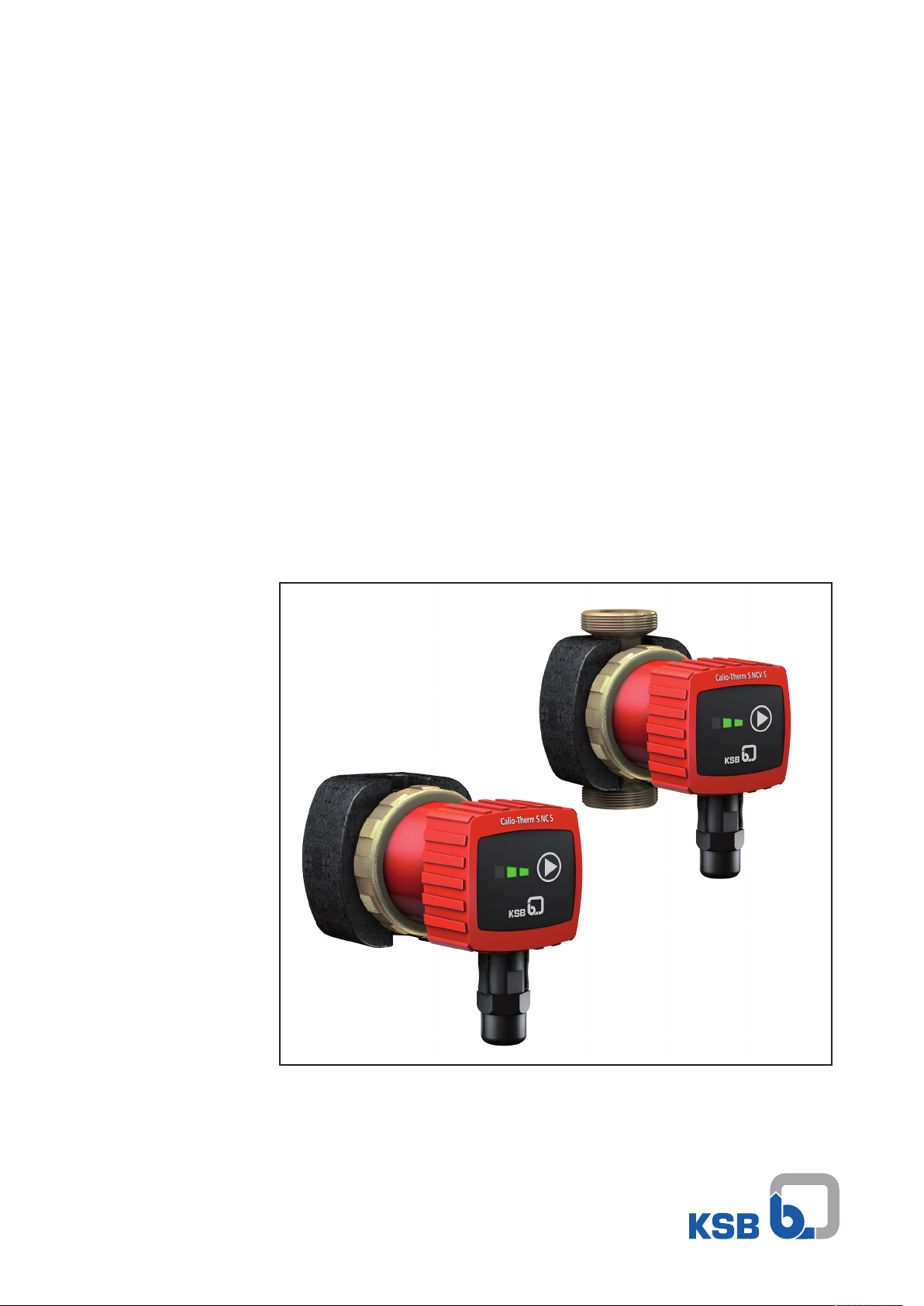
Drinking Water Pump
Calio-Therm S NC/NCV
Installation/Operating Manual
Page 2

Legal information/Copyright
Installation/Operating Manual Calio-Therm S NC/NCV
Original operating manual
All rights reserved. The contents provided herein must neither be distributed, copied, reproduced,
edited or processed for any other purpose, nor otherwise transmitted, published or made available to a
third party without the manufacturer's express written consent.
Subject to technical modification without prior notice.
© KSB SE & Co. KGaA, Frankenthal 23/03/2018
Page 3

Contents
Contents
Glossary .................................................................................................................................................. 5
1 General.................................................................................................................................................... 6
1.1 Principles ...........................................................................................................................................................6
1.2 Target group.....................................................................................................................................................6
1.3 Symbols .............................................................................................................................................................6
2 Safety...................................................................................................................................................... 7
2.1 Key to safety symbols/markings.......................................................................................................................7
2.2 General..............................................................................................................................................................7
2.3 Intended use .....................................................................................................................................................7
2.4 Personnel qualification and training...............................................................................................................8
2.5 Consequences and risks caused by non-compliance with this manual .........................................................8
2.6 Safety awareness ..............................................................................................................................................8
2.7 Safety information for the operator/user.......................................................................................................8
2.8 Safety information for maintenance, inspection and installation ................................................................9
2.9 Unauthorised modes of operation..................................................................................................................9
3 Transport/Temporary Storage/Disposal............................................................................................. 10
3.1 Checking the condition upon delivery..........................................................................................................10
3.2 Transport.........................................................................................................................................................10
3.3 Storage/preservation......................................................................................................................................10
3.4 Return to supplier...........................................................................................................................................10
3.5 Disposal ...........................................................................................................................................................11
4 Description of the Pump (Set)............................................................................................................. 12
4.1 General description ........................................................................................................................................12
4.2 Designation.....................................................................................................................................................12
4.3 Name plate......................................................................................................................................................12
4.4 Design details..................................................................................................................................................13
4.5 Configuration and function...........................................................................................................................13
4.6 Noise characteristics .......................................................................................................................................14
4.7 Scope of supply...............................................................................................................................................14
4.8 Dimensions and weight..................................................................................................................................14
5 Installation at Site................................................................................................................................ 15
5.1 Safety regulations...........................................................................................................................................15
5.2 Checks to be carried out prior to installation...............................................................................................15
5.3 Installing the pump set ..................................................................................................................................15
5.4 Connecting the piping ...................................................................................................................................16
5.5 Casing/insulation ............................................................................................................................................17
5.6 Electrical connection ......................................................................................................................................17
6 Commissioning/Start-up/Shutdown................................................................................................... 20
6.1 Commissioning/Start-up.................................................................................................................................20
6.1.1 Prerequisites for commissioning/start-up ......................................................................................... 20
6.1.2 Priming and venting the pump.........................................................................................................20
6.1.3 Start-up............................................................................................................................................... 21
6.1.4 Operation ...........................................................................................................................................21
6.2 Shutdown........................................................................................................................................................22
6.3 Operating limits..............................................................................................................................................22
6.3.1 Ambient temperature........................................................................................................................23
6.4 Shutdown/storage/preservation ....................................................................................................................23
6.4.1 Measures to be taken for shutdown ................................................................................................23
6.5 Returning to service .......................................................................................................................................23
7 Servicing/Maintenance........................................................................................................................ 24
7.1 Maintenance/inspection.................................................................................................................................24
7.2 Drainage/cleaning ..........................................................................................................................................24
Calio-Therm S NC/NCV
3 of 32
Page 4

Contents
7.3 Removing the pump set from the piping .....................................................................................................24
7.3.1 Removing the complete pump set from the piping ........................................................................24
8 Trouble-shooting.................................................................................................................................. 26
9 EU Declaration of Conformity............................................................................................................. 27
Index ..................................................................................................................................................... 28
4 of 32
Calio-Therm S NC/NCV
Page 5

Glossary
Glossary
Discharge line
The pipeline which is connected to the discharge
nozzle
Pump
Machine without drive, additional components or
accessories
Pump set
Complete pump set consisting of pump, drive,
additional components and accessories
Suction lift line/suction head line
The pipeline which is connected to the suction
nozzle
Calio-Therm S NC/NCV
5 of 32
Page 6
1 General
1 General
1.1 Principles
This operating manual is valid for the type series and variants indicated on the front
cover.
The manual describes the proper and safe use of this equipment in all phases of
operation.
The name plate indicates the type series and size as well as the main operating data.
They uniquely identify the pump (set) and serve as identification for all further
business processes.
In the event of damage, immediately contact your nearest KSB Service centre to
maintain the right to claim under warranty.
1.2 Target group
This operating manual is aimed at the target group of trained and qualified specialist
technical personnel. (ðSection2.4,Page8)
1.3 Symbols
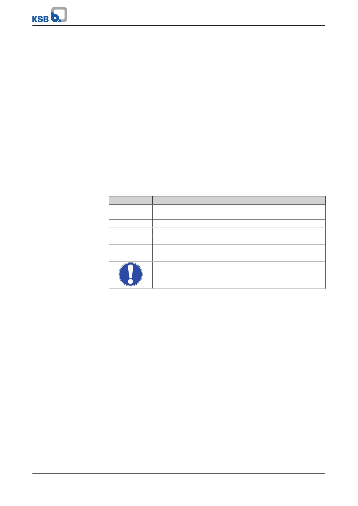
Table1: Symbols used in this manual
Symbol Description
✓ Conditions which need to be fulfilled before proceeding with the
step-by-step instructions
⊳ Safety instructions
⇨ Result of an action
⇨ Cross-references
1.
2.
Step-by-step instructions
Note
Recommendations and important information on how to handle
the product
6 of 32
Calio-Therm S NC/NCV
Page 7
2 Safety
!
DANGER
!
DANGER
!
WARNING
CAUTION
2 Safety
All the information contained in this section refers to hazardous situations.
In addition to the present general safety information the action-related safety
information given in the other sections must be observed.
2.1 Key to safety symbols/markings
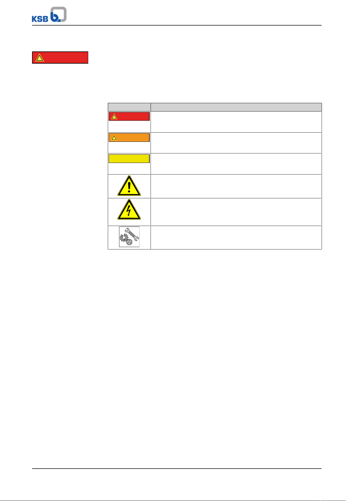
Table2: Definition of safety symbols/markings
Symbol Description
DANGER
This signal word indicates a high-risk hazard which, if not avoided,
will result in death or serious injury.
WARNING
This signal word indicates a medium-risk hazard which, if not
avoided, could result in death or serious injury.
CAUTION
This signal word indicates a hazard which, if not avoided, could
result in damage to the machine and its functions.
General hazard
In conjunction with one of the signal words this symbol indicates a
hazard which will or could result in death or serious injury.
Electrical hazard
In conjunction with one of the signal words this symbol indicates a
hazard involving electrical voltage and identifies information about
protection against electrical voltage.
Machine damage
In conjunction with the signal word CAUTION this symbol indicates
a hazard for the machine and its functions.
2.2 General
This operating manual contains general installation, operating and maintenance
instructions that must be observed to ensure safe operation of the system and
prevent personal injury and damage to property.
The safety information in all sections of this manual must be complied with.
The operating manual must be read and understood by the responsible specialist
personnel/operators prior to installation and commissioning.
The contents of this operating manual must be available to the specialist personnel
at the site at all times.
Information attached directly to the product must always be complied with and kept
in a perfectly legible condition at all times. This applies to, for example:
▪ Flow direction arrow
▪ Markings for connections
▪ Name plate
The operator is responsible for ensuring compliance with all local regulations not
taken into account in this operating manual.
2.3 Intended use
▪ The pump (set) must only be operated in the fields of application and within the
use limits specified in the other applicable documents.
▪ Only operate pumps/pump sets which are in perfect technical condition.
▪ Do not operate the pump (set) in partially assembled condition.
▪ Only use the pump to handle the fluids described in the data sheet or product
literature of the pump model or variant.
▪ Never operate the pump without the fluid to be handled.
Calio-Therm S NC/NCV
7 of 32
Page 8

2 Safety
▪ Observe the minimum flow rate and maximum flow rate indicated in the data
sheet or product literature (e.g. to prevent overheating, cavitation damage,
bearing damage).
▪ Do not throttle the flow rate on the suction side of the pump (to prevent
cavitation damage).
▪ Consult the manufacturer about any use or mode of operation not described in
the data sheet or product literature.
2.4 Personnel qualification and training
All personnel involved must be fully qualified to transport, install, operate, maintain
and inspect the machinery this manual refers to.
The responsibilities, competence and supervision of all personnel involved in
transport, installation, operation, maintenance and inspection must be clearly
defined by the operator.
Deficits in knowledge must be rectified by means of training and instruction
provided by sufficiently trained specialist personnel. If required, the operator can
commission the manufacturer/supplier to train the personnel.
Training on the pump (set) must always be supervised by technical specialist
personnel.
2.5 Consequences and risks caused by non-compliance with this manual
▪ Non-compliance with these operating instructions will lead to forfeiture of
warranty cover and of any and all rights to claims for damages.
▪ Non-compliance can, for example, have the following consequences:
– Hazards to persons due to electrical, thermal, mechanical and chemical
effects and explosions
– Failure of important product functions
– Failure of prescribed maintenance and servicing practices
– Hazard to the environment due to leakage of hazardous substances
2.6 Safety awareness
In addition to the safety information contained in this manual and the intended use,
the following safety regulations shall be complied with:
▪ Accident prevention, health regulations and safety regulations
▪ Explosion protection regulations
▪ Safety regulations for handling hazardous substances
▪ Applicable standards, directives and laws
2.7 Safety information for the operator/user
▪ Fit protective equipment (e.g. contact guards) supplied by the operator for hot,
cold or moving parts, and check that the equipment functions properly.
▪ Do not remove any protective equipment (e.g. contact guards) during operation.
▪ Contain leakages (e.g. at the shaft seal) of hazardous fluids handled (e.g.
explosive, toxic, hot) so as to avoid any danger to persons and the environment.
Adhere to all relevant laws.
▪ Eliminate all electrical hazards. (In this respect refer to the applicable national
safety regulations and/or regulations issued by the local energy supply
companies.)
▪ If shutting down the pump does not increase potential risk, fit an emergency-
stop control device in the immediate vicinity of the pump (set) during pump set
installation.
8 of 32
Calio-Therm S NC/NCV
Page 9

2 Safety
2.8 Safety information for maintenance, inspection and installation
▪ Modifications or alterations of the pump (set) are only permitted with the
manufacturer's prior consent.
▪ Use only original spare parts or parts/components authorised by the
manufacturer. The use of other parts/components can invalidate any liability of
the manufacturer for resulting damage.
▪ The operator ensures that maintenance, inspection and installation is performed
by authorised, qualified specialist personnel who are thoroughly familiar with
the manual.
▪ Only carry out work on the pump (set) during standstill of the pump.
▪ Only perform work on the pump set when it has been disconnected from the
power supply (de-energised).
▪ The pump (set) must have cooled down to ambient temperature.
▪ Pump pressure must have been released and the pump must have been drained.
▪ When taking the pump set out of service always adhere to the procedure
described in the manual. (ðSection6.4,Page23)
▪ Decontaminate pumps which handle fluids posing a health hazard.
▪ As soon as the work has been completed, re-install and re-activate any safety-
relevant devices and protective devices. Before returning the product to service,
observe all instructions on commissioning. (ðSection6.1,Page20)
2.9 Unauthorised modes of operation
Never operate the pump (set) outside the limits stated in the data sheet and in this
manual.
The warranty relating to the operating reliability and safety of the supplied pump
(set) is only valid if the equipment is used in accordance with its intended use.
Calio-Therm S NC/NCV
9 of 32
Page 10
3 Transport/Temporary Storage/Disposal
3 Transport/Temporary Storage/Disposal
3.1 Checking the condition upon delivery
1. On transfer of goods, check each packaging unit for damage.
2. In the event of in-transit damage, assess the exact damage, document it and
notify KSB or the supplying dealer and the insurer about the damage in writing
immediately.
3.2 Transport
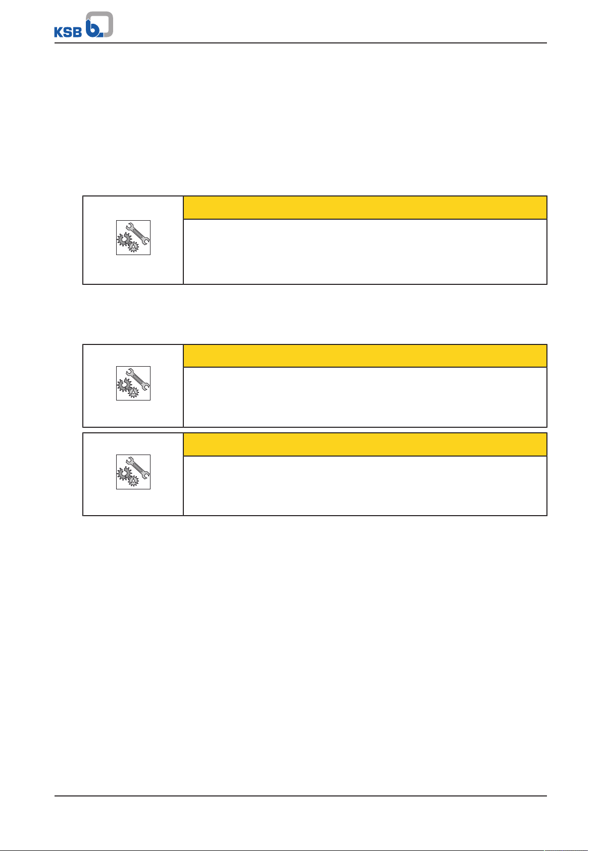
CAUTION
Improper pump transport
Damage to the pump!
▷ Never suspend the pump/pump set from the power cable.
▷ Prevent the pump (set) from getting knocked or dropped.
3.3 Storage/preservation
If commissioning is to take place some time after delivery, we recommend that the
following measures be taken for pump (set) storage.
CAUTION
Damage during storage due to humidity, dirt, or vermin
Corrosion/contamination of the pump (set)!
▷ For outdoor storage cover the packed or unpacked pump (set) and accessories
with waterproof material.
CAUTION
Wet, contaminated or damaged openings and connections
Leakage or damage to the pump!
▷ Clean and cover pump openings and connections as required prior to putting
the pump into storage.
Store the pump (set) in a dry, protected room where the atmospheric humidity is as
constant as possible.
If properly stored indoors, the equipment is protected for a maximum of 12months.
For storing a pump (set) which has already been operated, observe the instructions
in (ðSection6.4.1,Page23) .
3.4 Return to supplier
1. Drain the pump as per operating instructions.
2. Flush and clean the pump, particularly if it has been used for handling noxious,
explosive, hot or other hazardous fluids.
3. If the pump has handled fluids whose residues could lead to corrosion damage
in the presence of atmospheric humidity or could ignite upon contact with
oxygen also neutralise the pump and blow through with anhydrous inert gas to
ensure drying.
4. Always complete and enclose a certificate of decontamination when returning
the pump.
Indicate any safety measures and decontamination measures taken.
10 of 32
Calio-Therm S NC/NCV
Page 11

3 Transport/Temporary Storage/Disposal
3.5 Disposal
WARNING
Fluids handled, consumables and supplies which are hot and/or pose a health
hazard
Hazard to persons and the environment!
▷ Collect and properly dispose of flushing fluid and any fluid residues.
▷ Wear safety clothing and a protective mask if required.
▷ Observe all legal regulations on the disposal of fluids posing a health hazard.
1. Dismantle the pump (set).
Collect greases and other lubricants during dismantling.
2. Separate and sort the pump materials, e.g. by:
- Metals
- Plastics
- Electronic waste
- Greases and other lubricants
3. Dispose of materials in accordance with local regulations or in another
controlled manner.
Calio-Therm S NC/NCV
11 of 32
Page 12

4 Description of the Pump (Set)
1
2
3
4
Calio-Therm S NCV S
1~230V 50/60 Hz Max 0,04 A
Class F IP42 PN10 TF60
Material Nr. 29 134 813
ProdNr.
CE
2016w35-0867
Made in Germany
Johann-Klein-Straße 9
Deutschland
67227 Frankenthal
KSB SE & Co. KGaA
4 Description of the Pump (Set)
4.1 General description
▪ Non-self-priming in-line pump
▪ Pump for handling drinking water of up to 65°C
4.2 Designation
Example: Calio-Therm S NCV S
Table3: Designation key
Code Description
Calio-ThermS Type series
NCV Design
NC Fixed speed
NCV Fixed speed with integrated non-return valve and shut-
off valve (ball valve)
S Connection variants
S With plug-type connection
K With integrated power cable (2m length) and
shockproof plug (plug typeF)
Key to the series code
4.3 Name plate
Fig.1: Name plate (example)
1 Size 2 Voltage, frequency, max. input
power, thermal class, enclosure,
max. operating pressure,
temperature class
3 Material number 4 Series code
Example: 2016w35-0867
Table4: Key to the series code
Code Description
2016 Year 2016
w35 Week
0867 Consecutive number
12 of 32
Calio-Therm S NC/NCV
Page 13

4 Description of the Pump (Set)
1 2 3 4 5 6 7 8 9
10
11
4.4 Design details
▪ Maintenance-free glandless pump
▪ Screw-ended
▪ 3 speed levels
Operating modes
▪ Operation at fixed speed level
Manual functions
▪ Setting the speed level
Drive
▪ Short-circuit-proof electric motor
▪ 230V, 50Hz/60Hz
▪ IP42 enclosure
▪ Thermal class F
▪ Temperature class TF60
▪ Interference emission EN55014-1:2006+ A1:2009+ A2:2011, EN61000-3-2:2006+
A1:2009+ A2:2009, EN61000-3-3:2008
▪ Interference immunity EN55014-2:1997+ A1:2001+ A2:2008
Bearings
▪ Product-lubricated
4.5 Configuration and function
Fig.2: Sectional drawing of the pump
1 Pump casing 2 Check valve (only with 1 ¼")
3 Rotor 4 Union nut
Calio-Therm S NC/NCV
13 of 32
Page 14

Design
Function
4 Description of the Pump (Set)
5 Rotor 6 Motor housing
7 Electronics 8 Casing cover
9 LED display panel with pushbutton 10 Power connection
11 Ball check valve (only with 1 ¼")
The pump is designed with a radial fluid inlet and a radial outlet arranged on the
same axis. The impeller is rigidly connected to the motor shaft.
The motor housing is equipped with a terminal box. Mechanical sealing is not
required as the rotating assembly is completely isolated from the stator winding. The
rotating assembly is lubricated and cooled by the fluid pumped. The advanced
lubricating system and precision-balanced impeller ensure smooth running and a
long service life.
The fluid enters the pump via the suction nozzle and is accelerated outward in a
cylindrical flow by the rotating impeller, which is driven by the motor shaft. In the
flow passage of the pump casing the kinetic energy of the fluid is converted into
pressure energy. The fluid is pumped to the discharge nozzle, where it leaves the
pump.
4.6 Noise characteristics
Table5: Noise characteristics [dBA]
Sound pressure level
All 45 max.
4.7 Scope of supply
Depending on the model, the following items are included in the scope of supply:
▪ Pump set
▪ Installation/operating manual
▪ Plastic caps
▪ Plug-type connection or integrated connection cable
▪ Insulation shells
4.8 Dimensions and weight
For dimensions and weights please refer to the type series booklet of the pump (set).
14 of 32
Calio-Therm S NC/NCV
Page 15

5 Installation at Site
✔ ✔✔ ✘ ✘✘
✔ ✔✔ ✘ ✘✘
5 Installation at Site
5.1 Safety regulations
DANGER
Installation in potentially explosive atmospheres
Explosion hazard!
▷ Never install the pump in potentially explosive atmospheres.
▷ Observe the information given in the data sheet and on the name plates of the
pump system.
5.2 Checks to be carried out prior to installation
Before beginning with the installation check the following:
▪ The pump set can be operated on the power supply network according to the
data on the name plate.
▪ The fluid to be handled matches the description of suitable fluids.
5.3 Installing the pump set
Install the pump set in an easily accessible place.
CAUTION
Ingress of fluid into the motor
Damage to the pump set!
▷ Install the pump set with the pump shaft in a horizontal position. Connect the
piping without transmitting any stresses and strains.
NOTE
We recommend installing shut-off valves upstream and downstream of the pump.
Make sure that no leaking water can drip into the pump motor or terminal box.
Table6: Permissible installation positions
Sizes
Calio-Therm S NC
Calio-Therm S NCV
An arrow on the pump casing indicates the direction of flow.
The plug-type connection/ cable connection integrated in the pump can be fixed in
any position (e.g. pointing downward). To do so, loosen the product-integrated
union nut and move the pump head (connection housing including motor) into the
required position. Then tighten the union nut.
NOTE
The direction of flow of a vertically installed pump should be upwards.
Calio-Therm S NC/NCV
15 of 32
Page 16

5 Installation at Site
CAUTION
Air entering the pump
Damage to vertically installed pump sets whose direction of flow is downwards!
▷ Fit a vent valve at the highest point of the suction line.
NOTE
To prevent any impurities from collecting in the pump do not install the pump at
the lowest point of the system.
1. The circulator is usually installed in the piping directly upstream of the drinking
water storage tank. The water is pumped from the last tapping point via the
circulation line back to the storage tank.
2. Install a lift check valve on the pump's discharge side. It prevents backflow
through the pump when the tap is opened.
3. A shut-off valve is installed on the pump's suction side to facilitate maintenance.
Calio-Therm S NCV comes with a lift check valve and a shut-off option integrated
in the lower pump section.
4. Install the pump with the pump shaft in a horizontal position. Connect the
piping without transmitting any stresses and strains.
An arrow on the pump casing indicates the direction of flow.
CAUTION
Heat building up at motor housing and pump casing
Pump overheating!
▷ Never insulate the motor and electronic system housings.
5.4 Connecting the piping
WARNING
Impermissible loads acting on the pump nozzles
Risk of burns by leakage of hot fluids!
▷ Do not use the pump as an anchorage point for the piping.
▷ Anchor the pipes in close proximity to the pump and connect them without
transmitting any stresses or strains.
▷ Take appropriate measures to compensate for thermal expansion of the piping.
CAUTION
Contamination/dirt in the piping
Damage to the pump!
▷ Flush the piping prior to commissioning or replacing the pump. Remove any
foreign matter.
16 of 32
Calio-Therm S NC/NCV
Page 17

5 Installation at Site
NOTE
Installing check and shut-off elements in the system is recommended, depending on
the type of plant and pump. However, such elements must not obstruct proper
drainage or hinder disassembly of the pump.
ü Suction lift lines have been laid with a rising slope, suction head lines with a
downward slope towards the pump.
ü The nominal diameters of the pipes are equal to or greater than the nominal
diameters of the pump nozzles.
ü The pipelines have been anchored in close proximity to the pump and connected
without transmitting any stresses or strains.
1. Thoroughly clean, flush and blow through all vessels, pipelines and connections
(especially of new installations).
CAUTION
Welding beads, scale and other impurities in the piping
Damage to the pump!
▷ Free the piping from any impurities.
5.5 Casing/insulation
WARNING
The pump takes on same temperature as the fluid handled
Risk of burns!
▷ Insulate the volute casing.
▷ Fit protective equipment.
CAUTION
Heat building up at motor housing and pump casing
Pump overheating!
▷ Never insulate the motor and electronic system housings.
5.6 Electrical connection
DANGER
Electrical connection work by unqualified personnel
Risk of fatal injury due to electric shock!
▷ Always have the electrical connections installed by a trained and qualified
electrician.
▷ Observe regulations IEC 60364 and, for explosion-proof models, EN60079.
DANGER
Work performed on an energised terminal box
Danger of death from electric shock!
▷ Switch off the power supply at least 5 minutes prior to commencing work and
ensure that it cannot be switched on again unintentionally.
Calio-Therm S NC/NCV
17 of 32
Page 18

5 Installation at Site
24+/- 1.0
12+/- 1.0
1 2
WARNING
Incorrect connection to the mains
Damage to the mains network, short circuit!
▷ Observe the technical specifications of the local energy supply companies.
1. The pumps do not require any motor protection.
All pumps are designed for connection to 230VAC50/60Hz and delivered with a
plug-type connection (supplied but not fitted) or integrated power cable with mains
plug depending on the version.
The power cable needs to be wired to the supplied plug.
After the cable/plug assembly has been completed, connect the plug to the
corresponding jack at the pump (IP42).
Table7: Power cable
Cable Cable type
Outside diameter of the cable 5,5 - 10,0mm
Outside diameter of the core (including
insulation)
Cable cross-sections 0,75mm2 - 1,5mm2 massive or fine core cable
Connecting the cable at the pump
1. Verify the supply voltage at the site against the data on the name plate of the
pump.
2. Switch off the pump's power supply. Secure it against unintentional start-up.
Verify that the pump is de-energised.
3. Strip the power cable as shown in the diagram.
At the cable to be inserted into the plug, strip about 24mm of the sheath. Then
strip at least 12mm of the insulation at each strand (see illustration).
2,95mm max.
18 of 32
Fig.3: Stripping the cable
4. Remove the supplied plug-type connector from its packaging. Undo and remove
the screwed-on cable gland. Feed the stripped cable through the cable gland.
Fig.4: Plug-type connection
1 Strain relief device
2 Cable gland
Calio-Therm S NC/NCV
Page 19

5 Installation at Site
1
1 2
3
NOTE
When fitting the power cable to the plug-type connection make sure to insert the
strain relief device into the cable gland in the correct position. Only in its correct
installation position can the strain relief device function correctly in combination
with the cable gland.
Otherwise the strain relief device will be pressed onto the blue locking/unlocking
mechanism of the plug, which causes it to open and release the cores.
5. Insert the stripped cores/strands of the cable into the corresponding terminals L,
N and Earth (PE) of the plug. The markings are shown on the blue removal
mechanism (ring). The automatic locking mechanism locks the strand in place,
establishes contact and prevents the strand from sliding out of the plug.
A marking underneath the PE terminal helps identify the correct connection.
After the cable has been wired to the plug, screw the cable entry onto the plug
and tighten it.
Fig.5: Plug-type connection with marking
1 PE marking
Fig.6: Connections at the plug
1 Phase (230VAC) 2 Neutral (N)
3 Earth (embossed marking on the
ring) (PE)
6. After the cable/plug assembly has been completed, connect the plug to the jack
at the pump.
7. The cores/strands can be removed from the plug by pressing down the blue ring.
Calio-Therm S NC/NCV
19 of 32
Page 20

6 Commissioning/Start-up/Shutdown
6 Commissioning/Start-up/Shutdown
6.1 Commissioning/Start-up
6.1.1 Prerequisites for commissioning/start-up
Before commissioning/starting up the pump set, make sure that the following
conditions are met:
▪ The pump set has been properly connected to the power supply and is equipped
with all protection devices.
▪ The pump has been primed with the fluid to be handled. The pump has been
vented.
▪ Before commissioning/starting up the pump set, make sure that the system is free
of contamination and foreign objects.
6.1.2 Priming and venting the pump
CAUTION
Increased wear due to dry running
Damage to the pump set!
▷ Never operate the pump set without liquid fill.
▷ Never close the shut-off element in the suction line and/or supply line during
pump operation.
1. Fill the system with the fluid to be handled.
CAUTION
Operation without the fluid to be handled
Damage to the pump!
▷ Prime the pump with the fluid to be handled.
2. Vent the system thoroughly. To this end, loosen the union nut of the pump so
that air can escape from the pump.
3. Carefully open the inlet line until water escapes from the pump.
DANGER
Moisture in the electrical connection area
Short circuit in the pump!
▷ De-energise the pump.
4. Tighten the union nut hand tight with a suitable tool.
5. Start up the pump set.
6. Audible flow noises indicate that there is air in the piping.
Repeat the venting procedure, if necessary, to remove all air from the system.
20 of 32
Calio-Therm S NC/NCV
Page 21

6 Commissioning/Start-up/Shutdown
1 2
6.1.3 Start-up
DANGER
Non-compliance with the permissible pressure and temperature limits if the pump
is operated with the suction and discharge lines closed.
Hot fluids escaping!
▷ Never operate the pump with the shut-off elements in the suction line and/or
discharge line closed.
▷ Only start up the pump set against a slightly or completely open discharge-side
shut-off element.
DANGER
Excessive temperatures due to insufficient lubrication of shaft seal
Damage to the pump set!
▷ Never operate the pump set without liquid fill.
▷ Prime the pump as per operating instructions.
▷ Always operate the pump within the permissible operating range.
CAUTION
Abnormal noises, vibrations, temperatures or leakage
Damage to the pump!
▷ Switch off the pump (set) immediately.
▷ Eliminate the causes before returning the pump set to service.
ü The system piping has been cleaned.
ü Pump, suction line and inlet tank, if fitted, have been vented and primed with
the fluid to be handled.
ü The lines for priming and venting have been closed.
1. Fully open the shut-off element in the suction head/suction lift line.
2. Close or slightly open the shut-off element in the discharge line.
3. Start up the motor.
Position of shut-off valve of Calio-Therm S NCV
Fig.7: Position of shut-off valve of Calio-Therm S NCV
1 Open position 2 Closed position
6.1.4 Operation
The pump starts up when it is connected to the power supply.
The number of lit LEDs indicates the speed level at which the pump is operated
(operation at constant speed). 3 speed levels can be set via the pushbutton. The
pump can be optimally adjusted to the existing system by selecting the most suitable
characteristic curve. 3 flashing LEDs indicate a fault or error.
Calio-Therm S NC/NCV
21 of 32
Page 22

6 Commissioning/Start-up/Shutdown
3 2 1 4
Fig.8: Indication of speed level
1 Speed level 1 2 Speed level 2
3 Speed level 3 4 Pushbutton
6.2 Shutdown
ü The shut-off element in the suction line is and remains open.
1. Close the shut-off element in the discharge line.
2. Switch off the motor and make sure the pump set runs down smoothly to a
standstill.
NOTE
If the discharge line is equipped with a check valve, the shut-off element in the
discharge line may remain open, provided the site's requirements and regulations
are taken into account and observed.
For prolonged shutdown periods:
1. Close the shut-off element in the suction line.
CAUTION
Risk of freezing during prolonged pump shutdown periods
Damage to the pump!
▷ Drain the pump and the cooling/heating chambers (if any) or otherwise protect
them against freezing.
6.3 Operating limits
DANGER
Non-compliance with operating limits for pressure, temperature, fluid handled and
speed
Hot fluids escaping!
▷ Comply with the operating data indicated in the data sheet.
▷ Avoid prolonged operation against a closed shut-off element.
▷ Never operate the pump at product temperatures exceeding those specified in
the data sheet or on the name plate.
22 of 32
Calio-Therm S NC/NCV
Page 23

6 Commissioning/Start-up/Shutdown
6.3.1 Ambient temperature
CAUTION
Operation outside the permissible ambient temperature
Damage to the pump (set)!
▷ Observe the specified limits for permissible ambient temperatures.
Observe the following parameters and values during operation:
Table8: Permissible ambient temperatures
Permissible ambient temperature Value
Maximum 40 °C
Minimum 0 °C
6.4 Shutdown/storage/preservation
6.4.1 Measures to be taken for shutdown
The pump (set) remains installed
ü Sufficient fluid is supplied for the operation check run of the pump.
1. Start up the pump (set) regularly between once a month and once every three
months for approximately five minutes during prolonged shutdown periods.
This will prevent the formation of deposits within the pump and the pump
intake area.
The pump is removed from the pipe and stored
The pump has been properly drained and the safety instructions for dismantling the
pump have been observed.
Observe any additional instructions and information provided. (ðSection3,Page10)
6.5 Returning to service
For returning the pump to service observe the sections on commissioning/start-up
and the operating limits.
In addition, carry out all servicing/maintenance operations before returning the
pump (set) to service.
WARNING
Failure to re-install or re-activate protective devices
Risk of injuries by escaping fluid!
▷ As soon as the work is completed, re-install and/or re-activate any safety-
relevant and protective devices.
Calio-Therm S NC/NCV
23 of 32
Page 24

7 Servicing/Maintenance
7 Servicing/Maintenance
7.1 Maintenance/inspection
The circulators are almost maintenance-free.
If the pump has not been in operation for a prolonged period of time or if the
system is severely contaminated, the rotor can become blocked.
Remove the pump head (loosen the union nut and take off pump head) to access and
remove the impeller. After the pump head has been removed, tighten the union nut
to a tightening torque of 30Nm with a belt wrench.
Fig.9: Belt wrench for tightening the union nut
This allows unblocking the rotor and/or cleaning the pump.
NOTE
Any repairs on the pump must only be performed by one of our authorised service
partners.
In the event of a failure, please contact your heating system engineer.
7.2 Drainage/cleaning
WARNING
Fluids, consumables and supplies which are hot and/or pose a health hazard
Hazard to persons and the environment!
▷ Collect and properly dispose of flushing fluid and any residues of the fluid
handled.
▷ Wear safety clothing and a protective mask if required.
▷ Observe all legal regulations on the disposal of fluids posing a health hazard.
1. Always flush and clean the pump before transporting it to the workshop.
Provide a cleaning record for the pump.
7.3 Removing the pump set from the piping
7.3.1 Removing the complete pump set from the piping
DANGER
24 of 32
Electrical connection work by unqualified personnel
Risk of fatal injury due to electric shock!
▷ Always have the electrical connections installed by a trained and qualified
electrician.
▷ Observe regulations IEC 60364 and, for explosion-proof models, EN60079.
Calio-Therm S NC/NCV
Page 25

7 Servicing/Maintenance
DANGER
Strong magnetic field in the rotor area
Danger of death for persons with pacemaker!
▷ Keep a safety distance of at least 0.3 m.
DANGER
Pump acting as a generator when running in reverse
Danger to life from hazardous induction voltage at the motor terminals!
▷ Prevent the fluid from flowing back by closing the shut-off elements.
WARNING
Danger by strong magnetic field
Danger of crushing injuries when pulling out the rotor!
Due to the strong magnetic field the rotor can be suddenly pulled back into its
original position!
Danger of magnetic parts near the rotor being attracted!
▷ The rotor must generally only be removed from the motor housing by
authorised specialist personnel.
▷ Remove any magnetic parts from the vicinity of the rotor.
▷ Keep the assembly area clean.
▷ Keep a safety distance of at least 0.3m from electronic components.
CAUTION
Strong magnetic field in the rotor area
Interference with magnetic data carriers, electronic devices, components and
instruments!
Uncontrolled magnetic attraction forces between magnetic components, tools or
similar!
▷ Remove any magnetic parts from the vicinity of the rotor.
▷ Keep the assembly area clean.
CAUTION
Danger by strong magnetic field
Negative impact on or damage to electrical devices!
▷ The rotor must generally only be removed from the motor housing by
authorised specialist personnel.
ü The relevant notes and steps stated been observed/carried out.
ü The pump has cooled down to ambient temperature.
ü A container for collecting the fluid has been positioned underneath the pump
set.
1. De-energise the pump set (disconnect the motor) and ensure that it cannot be
re-energised unintentionally.
2. Close the shut-off elements.
3. Disconnect the discharge and suction nozzles from the piping.
4. Remove the complete pump set from the piping.
Calio-Therm S NC/NCV
25 of 32
Page 26

8 Trouble-shooting
8 Trouble-shooting
WARNING
Improper work to remedy faults
Risk of injury!
▷ For any work performed to remedy faults, observe the relevant information
given in this operating manual and/or in the product literature provided by the
accessories manufacturer.
If problems occur that are not described in the following table, consultation with the
KSB customer service is required.
Pump is running, but does not deliver
A
Pump does not start up or pump running irregularly
B
Pump running but not delivering water
C
Noises during pump operation
D
Table9: Trouble-shooting
A B C D Possible cause Remedy
✘ - - - Pump not connected to power supply Check the power supply and fuses or
reset the voltage (interrupt and re-establish
power supply).
✘ - - - Pump blocked (e.g. due to contamination) (ðSection7,Page24)
✘ - - - Defective motor Replace the pump.
- ✘ - - Impurities in the pump See section on maintenance.
- - ✘ - Air in the system Vent the system and the pump.
- - ✘ - Gate valve closed Open the gate valve.
- - - ✘ Excessive pump power output Select a lower speed level.
- - - ✘ System pressure too low Increase the system pressure by filling more water
into the boiler.
- - - ✘ Air in the system Vent the pump and piping.
1)
1) Release pump pressure before attempting to remedy faults on parts which are subjected to pressure.
26 of 32
Calio-Therm S NC/NCV
Page 27

9 EU Declaration of Conformity
9 EU Declaration of Conformity
Manufacturer: KSB SE & Co. KGaA
Johann-Klein-Straße 9
67227 Frankenthal (Germany)
The manufacturer herewith declares that the product:
Calio-Therm S NC / NCV
Serial number range: 2018w01 to 2019w52
▪ is in conformity with the provisions of the following Directives as amended from time to time:
– Electromagnetic Compatibility Directive 2014/30/EU
– Low-voltage Directive 2014/35/EU
The manufacturer also declares that
▪ the following harmonised international standards have been applied:
– DINEN 55014-1, EN 55014-2
– DINEN 60335-1, EN 60335-2-51
– DINEN 61000-3-2, EN 61000-3-3
The EU Declaration of Conformity was issued in/on:
Frankenthal, 1 February 2018
Joachim Schullerer
Head of Product Development Pump Systems and Drives
KSB SE & Co. KGaA
Johann-Klein-Straße 9
67227 Frankenthal
Calio-Therm S NC/NCV
27 of 32
Page 28

Index
Index
B
Bearings13
C
Commissioning20
D
Designation12
Disposal11
Drive13
E
Event of damage6
F
Faults
Causes and remedies26
Fields of application7
I
Intended use7
K
Key to safety symbols/markings7
W
Warnings7
Warranty claims6
M
Manual functions13
N
Name plate12
O
Operating limits22
Operating modes13
P
Piping17
Preservation10, 23
R
Return to supplier10
Returning to service23
S
Safety7
Safety awareness8
Scope of supply14
Shutdown23
Start-up21
Storage10, 23
28 of 32
Calio-Therm S NC/NCV
Page 29

Page 30

Page 31

Page 32

KSB SE & Co. KGaA
Johann-Klein-Straße 9 • 67227 Frankenthal (Germany)
Tel. +49 6233 86-0
www.ksb.com
1157.88/05-EN
 Loading...