

KSB BoosterControl Advanced Operating Manual
BoosterControl Advanced
Installation/Operating Manual

Legal information/Copyright
Installation/Operating Manual BoosterControl Advanced
Original operating manual
All rights reserved. The contents provided herein must neither be distributed, copied, reproduced,
edited or processed for any other purpose, nor otherwise transmitted, published or made available to a
third party without the manufacturer's express written consent.
Subject to technical modification without prior notice.
© KSB SE & Co. KGaA, Frankenthal 12/03/2018

Contents
3 of 88
BoosterControl Advanced
Contents
1 General.................................................................................................................................................... 5
1.1 Principles ...........................................................................................................................................................5
1.2 Target group.....................................................................................................................................................5
1.3 Other applicable documents............................................................................................................................5
1.4 Symbols .............................................................................................................................................................5
2 Safety...................................................................................................................................................... 6
2.1 Key to safety symbols/markings.......................................................................................................................6
2.2 General..............................................................................................................................................................6
2.3 Intended use .....................................................................................................................................................6
2.4 Personnel qualification and training...............................................................................................................7
2.5 Consequences and risks caused by non-compliance with this operating manual........................................ 7
2.6 Safety awareness ..............................................................................................................................................7
2.7 Safety information for the user/operator.......................................................................................................7
2.8 Safety information for maintenance, inspection and installation work.......................................................7
2.9 Unauthorised modes of operation..................................................................................................................8
2.10 Software Changes.............................................................................................................................................8
2.11 Electromagnetic compatibility.........................................................................................................................8
3 Transport/Temporary Storage/Disposal............................................................................................... 9
3.1 Checking the condition upon delivery............................................................................................................9
3.2 Transport...........................................................................................................................................................9
3.3 Storage..............................................................................................................................................................9
3.4 Disposal .............................................................................................................................................................9
4 Description............................................................................................................................................ 10
4.1 General description ........................................................................................................................................10
4.2 Designation.....................................................................................................................................................10
4.3 Name plate......................................................................................................................................................10
4.4 Functions.........................................................................................................................................................10
4.5 Technical data.................................................................................................................................................11
4.5.1 Parameterisable inputs/outputs ........................................................................................................12
4.6 Combination options......................................................................................................................................12
4.7 Options............................................................................................................................................................13
4.8 Software scope of supply...............................................................................................................................13
4.9 Dimensions and weight..................................................................................................................................13
5 Installation at Site................................................................................................................................ 14
5.1 Safety regulations...........................................................................................................................................14
5.2 Checking ambient conditions ........................................................................................................................14
5.3 Installing BoosterControl Advanced..............................................................................................................14
5.4 Electrical connection ......................................................................................................................................14
5.4.1 Electrical connections ........................................................................................................................14
5.4.2 Connection to power supply .............................................................................................................17
5.4.3 Connecting/bridging the motor protection device..........................................................................17
5.4.4 Connecting the pump contactors .....................................................................................................18
5.4.5 Connecting the pressure sensor ........................................................................................................18
5.4.6 Connecting the dry running protection device................................................................................18
5.4.7 Other connections required depending on the operating mode...................................................18
5.4.8 Making optional connections ...........................................................................................................19
6 Operation.............................................................................................................................................. 21
6.1 Control panel..................................................................................................................................................21
6.1.1 "Traffic light" LEDs ............................................................................................................................21
6.1.2 Graphical display................................................................................................................................ 21
6.1.3 Menu keys ..........................................................................................................................................22
6.1.4 Navigation keys.................................................................................................................................. 26
6.2 Operating the device via the service interface.............................................................................................27

Contents
4 of 88
BoosterControl Advanced
6.3 Operating the device via the control panel..................................................................................................27
6.3.1 Displaying and changing parameters ...............................................................................................27
6.4 General functions ...........................................................................................................................................28
6.4.1 Setting the physical units ..................................................................................................................28
6.4.2 Saving/loading customer settings .....................................................................................................28
6.4.3 Saving/loading factory settings.........................................................................................................29
6.4.4 Resetting to default settings............................................................................................................. 29
6.4.5 Enabling/disabling the password ...................................................................................................... 29
6.4.6 Displaying general information ........................................................................................................ 29
6.4.7 Displaying status information ........................................................................................................... 30
6.5 General information on parameterisation ...................................................................................................31
6.6 User login........................................................................................................................................................31
7 Quick Start Instructions ....................................................................................................................... 32
8 Commissioning/Start-up/Shutdown................................................................................................... 34
8.1 Ambient conditions for commissioning and operation ...............................................................................34
8.2 Commissioning................................................................................................................................................34
8.2.1 Starting up the system....................................................................................................................... 34
8.3 Setting BoosterControl Advanced.................................................................................................................34
8.3.1 Setting the display language ............................................................................................................34
8.3.2 Setting the time/date.........................................................................................................................34
8.4 Basic configurations of the pressure booster system ...................................................................................34
8.4.1 Cascade control ..................................................................................................................................36
8.4.2 Cascade control - with jockey pump.................................................................................................37
8.4.3 Control with one frequency inverter (per system)...........................................................................38
8.4.4 Control with one frequency inverter per pump (sequential starting/stopping of pumps) ........... 41
8.4.5 Control with one frequency inverter per pump (synchronous operation of pumps), multiple
pump operation .................................................................................................................................42
8.4.6 Setting the frequency inverter parameters......................................................................................44
8.5 Application functions.....................................................................................................................................45
8.5.1 Setting the parameters for dry running protection ........................................................................45
8.5.2 Setting an alternative setpoint .........................................................................................................45
8.5.3 Parameterisation of inlet tank function...........................................................................................46
8.5.4 Parameterising the accumulator function (frequency-controlled systems only) ...........................49
8.5.5 Water flow detection (WSD) ............................................................................................................. 49
8.5.6 Fire-fighting function ........................................................................................................................51
8.5.7 Emergency power function (limitation of number of pumps)........................................................51
8.5.8 Automatic setpoint reduction in case of inlet pressure drop (ASR) ..............................................52
8.5.9 Configuring the functional check run ..............................................................................................52
8.5.10 Dynamic pressure compensation (DFS).............................................................................................52
8.5.11 Setting freely parameterisable inputs ..............................................................................................53
8.5.12 Setting freely configurable outputs ................................................................................................53
8.5.13 Configuration example......................................................................................................................54
8.5.14 Setting alternative setpoint using a timer .......................................................................................54
9 Servicing/Inspection............................................................................................................................. 55
9.1 Safety regulations...........................................................................................................................................55
9.2 Servicing/Inspection........................................................................................................................................55
9.2.1 Supervision of operation ................................................................................................................... 55
10 Parameter list ....................................................................................................................................... 56
11 Trouble-shooting.................................................................................................................................. 78
11.1 Fault messages................................................................................................................................................78
12 Related documents .............................................................................................................................. 81
12.1 Checklist for commissioning and inspection.................................................................................................81
13 EU Declaration of Conformity............................................................................................................. 82
Index ..................................................................................................................................................... 83
1 General
5 of 88
BoosterControl Advanced
1 General
1.1 Principles
This manual is supplied as an integral part of the type series indicated on the front
cover. The manual describes the proper and safe use of this equipment in all phases
of operation.
The name plate indicates the type series, the main operating data and the serial
number. The serial number uniquely describes the product and is used as
identification in all further business processes.
In the event of damage, immediately contact your nearest KSB service centre to
maintain the right to claim under warranty.
1.2 Target group
This operating manual is aimed at the target group of trained and qualified specialist
technical personnel.
1.3 Other applicable documents
Table1: Overview of other applicable documents
Document Contents
Logic diagram Description of electrical connections and
performance data
For accessories and/or integrated machinery components, observe the relevant
manufacturer's product literature.
1.4 Symbols
Table2: Symbols used in this manual
Symbol Description
✓ Conditions which need to be fulfilled before proceeding with the
step-by-step instructions
⊳ Safety instructions
⇨ Result of an action
⇨ Cross-references
1.
2.
Step-by-step instructions
Note
Recommendations and important information on how to handle
the product
2 Safety
6 of 88
BoosterControl Advanced
2 Safety
!
DANGER
All the information contained in this section refers to hazardous situations.
In addition to the present general safety information the action-related safety
information given in the other sections must be observed.
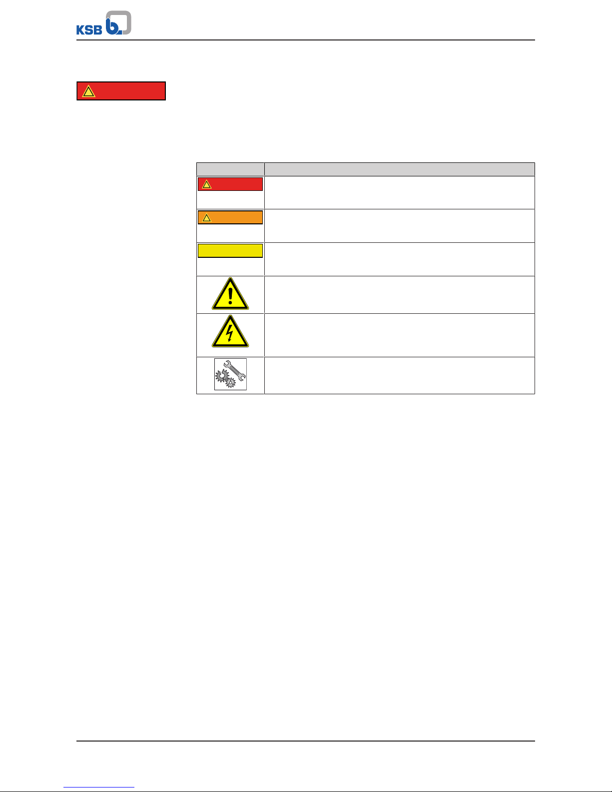
2.1 Key to safety symbols/markings
Table3: Definition of safety symbols/markings
Symbol Description
!
DANGER
DANGER
This signal word indicates a high-risk hazard which, if not avoided,
will result in death or serious injury.
!
WARNING
WARNING
This signal word indicates a medium-risk hazard which, if not
avoided, could result in death or serious injury.
CAUTION
CAUTION
This signal word indicates a hazard which, if not avoided, could
result in damage to the machine and its functions.
General hazard
In conjunction with one of the signal words this symbol indicates a
hazard which will or could result in death or serious injury.
Electrical hazard
In conjunction with one of the signal words this symbol indicates a
hazard involving electrical voltage and identifies information about
protection against electrical voltage.
Machine damage
In conjunction with the signal word CAUTION this symbol indicates
a hazard for the machine and its functions.
2.2 General
This operating manual contains general installation, operating and maintenance
instructions that must be observed to ensure safe operation of the system and
prevent personal injury and damage to property.
The safety information in all sections of this manual must be complied with.
The operating manual must be read and understood by the responsible specialist
personnel/operators prior to installation and commissioning.
The contents of this operating manual must be available to the specialist personnel
at the site at all times.
Information attached directly to the product must always be complied with and kept
in a perfectly legible condition at all times. This applies to, for example:
▪ Markings for connections
▪ Name plate
The operator is responsible for ensuring compliance with all local regulations not
taken into account in this operating manual.
2.3 Intended use
This product must not be operated beyond the values specified in the technical
product literature for the mains voltage, mains frequency, and ambient temperature,
or be used in any manner that is not compliant with the instructions provided in the
operating manual and in other, applicable documents.
The product must not be used in potentially explosive atmospheres.

2 Safety
7 of 88
BoosterControl Advanced
2.4 Personnel qualification and training
All personnel involved must be fully qualified to transport, install, operate, maintain
and inspect the product this manual refers to. The responsibilities, competence and
supervision of all personnel involved in installation, operation, maintenance and
inspection must be clearly defined by the operator.
Deficits in knowledge must be rectified by means of training and instruction
provided by sufficiently trained specialist personnel. If required, the operator can
commission the manufacturer/supplier to train the personnel.
Training on the product must always be supervised by specialist technical personnel.
2.5 Consequences and risks caused by non-compliance with this operating
manual
▪ Non-compliance with this operating manual will lead to forfeiture of warranty
cover and of any and all rights to claims for damages.
▪ Non-compliance can, for example, have the following consequences:
– Hazards to persons due to electrical, thermal, mechanical and chemical
effects and explosions
– Failure of important product functions
– Failure of prescribed maintenance and servicing practices
2.6 Safety awareness
In addition to the safety information contained in this manual and the intended use,
the following safety regulations shall be complied with:
▪ Accident prevention, health and safety regulations
▪ Explosion protection regulations
▪ Safety regulations for handling hazardous substances
▪ Applicable standards and legislation (e.g. EN50110-1)
2.7 Safety information for the user/operator
▪ Fit contact guards supplied by the operator for hot, cold or moving parts, and
check that the guards function properly.
▪ Do not remove any contact guards during operation.
▪ Provide the personnel with protective equipment and make sure it is used.
▪ Eliminate all electrical hazards. (In this respect, refer to the applicable national
safety regulations and/or regulations issued by the local energy supply
companies.)
2.8 Safety information for maintenance, inspection and installation work
▪ Modifications or alterations are only permitted with the manufacturer's prior
consent.
▪ Use only original spare parts or parts authorised by the manufacturer. The use of
other parts can invalidate any liability of the manufacturer for resulting damage.
▪ The operator ensures that all maintenance, inspection and installation work is
performed by authorised, qualified specialist personnel who are thoroughly
familiar with the manual.
▪ Any work on the product shall only be performed when it has been disconnected
from the power supply (de-energised).
▪ Carry out work on the product during standstill only.
▪ As soon as the work has been completed, re-install and/or re-activate any safety-
relevant and protective devices. Before returning the product to service, observe
all instructions on commissioning.

2 Safety
8 of 88
BoosterControl Advanced
2.9 Unauthorised modes of operation
Never operate the product outside the limits stated in the data sheet and in this
manual.
The warranty relating to the operating reliability and safety of the product supplied
is only valid if the product is used in accordance with its intended use.
2.10 Software Changes
The software has been specially created for this product and thoroughly tested.
It is impermissible to make any changes or additions to the software or parts of the
software. Software updates supplied by KSB are excluded from this rule.
2.11 Electromagnetic compatibility
EMC Directive 2004/108/EC ("Electromagnetic Compatibility") sets out the
requirements concerning the interference immunity and interference emissions of
electric and electronic equipment.
3 Transport/Temporary Storage/Disposal
9 of 88
BoosterControl Advanced
3 Transport/Temporary Storage/Disposal
3.1 Checking the condition upon delivery
1. On transfer of goods, check each packaging unit for damage.
2. In the event of in-transit damage, assess the exact damage, document it and
notify KSB or the supplying dealer (as applicable) and the insurer about the
damage in writing immediately.
3.2 Transport
▪ Transport the device in its original packaging.
▪ Observe the transport instructions on the original packaging.
▪ Keep the original packaging for future transport and storage.
3.3 Storage
If the ambient conditions for storage are met, the function of the control unit is
safeguarded even after a prolonged period of storage.
CAUTION
Damage during storage by humidity, dirt or vermin
Corrosion/contamination of the control unit!
▷ For outdoor storage cover the (packed or unpacked) control unit and
accessories with water-proof material.
Table4: Ambient conditions for storage
Ambient condition Value
Relative humidity 85% max. (non-condensing)
Ambient temperature -10°C to + 70°C
▪ Store the control unit in dry, vibration-free conditions and, if possible, in its
original packaging.
▪ Store the control unit in a dry room where the level of atmospheric humidity is as
constant as possible.
▪ Prevent excessive fluctuations in atmospheric humidity (see table on ambient
conditions for storage).
3.4 Disposal
The product is classified as special waste due to several installed components:
1. Dismantle the product.
2. Separate and sort the materials
e.g. by:
- Aluminium
- Plastic cover (recyclable plastic)
3. Dispose of materials in accordance with local regulations or in another
controlled manner.
PCBs, power electronics, capacitors and electronic components are all special
waste.
The requirements pertaining to RoHs 2002/95/EC are fulfilled.
4 Description
10 of 88
BoosterControl Advanced
4 Description
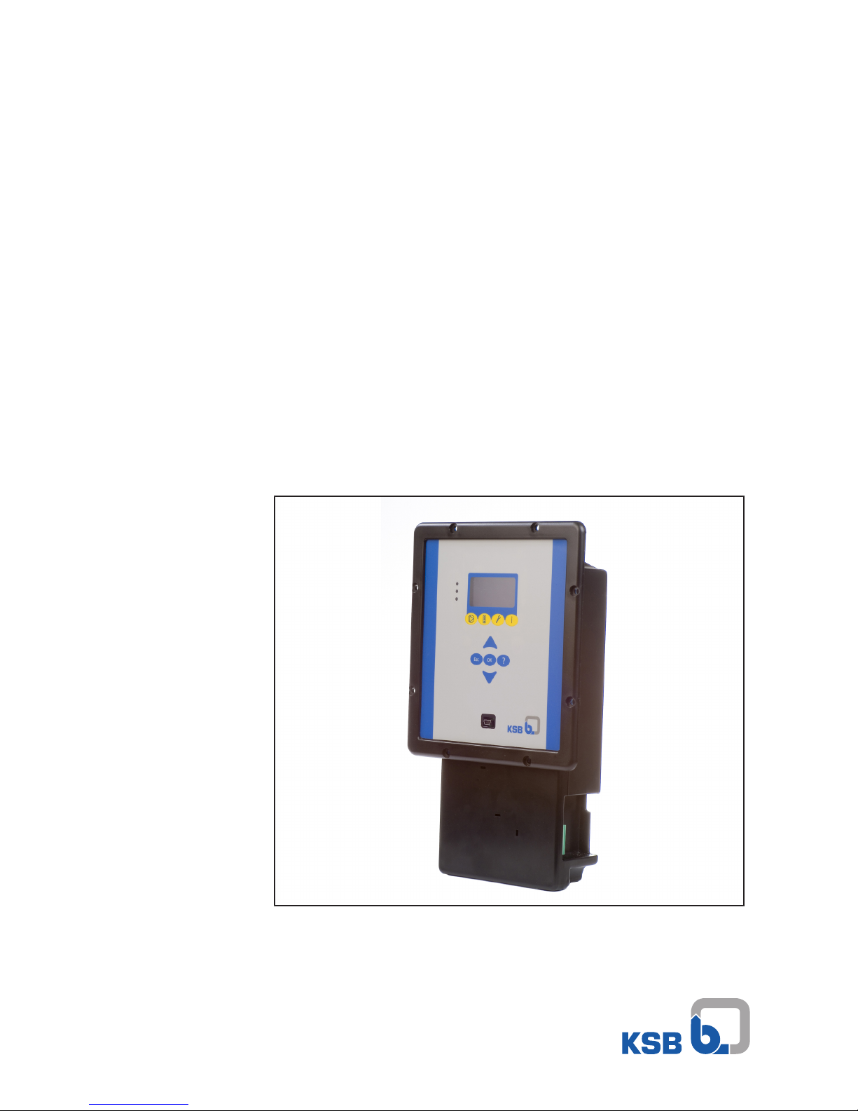
4.1 General description
▪ Control unit for pressure booster systems
With BoosterControl Advanced, up to 3 or 6 pump sets can be started, stopped and
controlled as a function of pressure.
4.2 Designation
Example: BCA 6
Table5: Key to the designation
Code Description
BCA BoosterControl Advanced
6 Number of pumps that can be connected
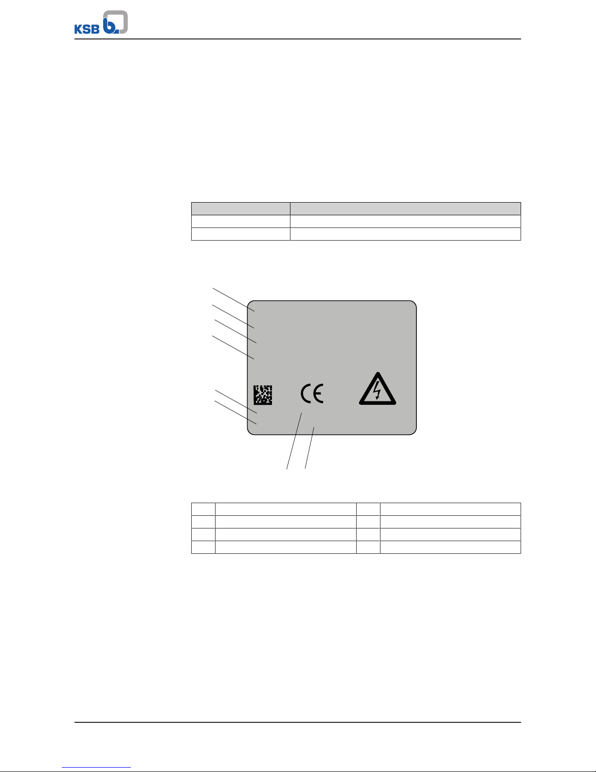
4.3 Name plate
BoosterControl 1.5 - 3P
P/N 01464675
S/N 010201211290018
Date 29-11-2012
Made in EU
230VAC
50/60Hz
IP20
15W
Warning!!!
High voltage
1
2
3
4
5
6
7 8
Fig.1: Name plate (example)
1 Type series, size 2 Ident. number
3 Series number 4 Year of construction
5 Input voltage 6 Mains frequency
7 Enclosure 8 Power input
4.4 Functions
Control system
Control of up to 3 or 6 pump sets as a function of pressure
The following functions, among others, are possible:
▪ Even distribution of operating hours among the pumps connected
▪ Automatic pump changeover
– as a function of operating hours
– in the case of a pump fault
▪ Pump starting and stopping in line with demand
▪ Functional check run
▪ Control of an inlet tank valve (for corresponding system configuration)

4 Description
11 of 88
BoosterControl Advanced
▪ Inlet tank control (for corresponding system configuration)
▪ Energy-saving operation
▪ Dynamic pressure setpoint compensation
▪ Base-load or peak-load pump operation (jockey function)
Monitoring
Monitoring of external conditions via digital and analog inputs
The following monitoring functions can be used:
▪ General fault message
▪ Individual fault messages (lack of water)
▪ Thermal monitoring of pump motors
▪ Sensor fault/broken wire
▪ Fault/warning per pump
▪ Monitoring of service interval
▪ Dry running detection via pressure switch or pressure sensor
▪ Operational availability, indicated via LEDs and display
▪ Level monitoring
▪ Fire alert recognition (with corresponding system configuration)
▪ Monitoring of the inlet tank valve (with corresponding system configuration)
▪ Water flow detection (water flow detector), including temperature monitoring
▪ Dry running protection
You can also assign up to 3inputs with freely configurable statuses or signals as an
option.
Communication
Communication with field bus systems via the following interfaces:
▪ Profibus
▪ Modbus RTU– RS485
Bus communication with frequency inverters is possible for the following
manufacturers:
▪ KSB PumpDrive
▪ Danfoss VLT 2800
▪ Danfoss Microdrive FC 51
▪ Danfoss Aquadrive FC 200
4.5 Technical data
Table6: Technical data
Characteristic Value
Power supply
Rated voltage 1~ 230 V AC ±10 %
Mains frequency 50/60 Hz
Rated insulation voltage 500 V AC
Standby current input ~ 35 mA
Standby power 7,5 W
Enclosure
Housing IP20
For control cabinet installation IP55
Digital inputs
Motor protection 24 V DC
Pressure switch 24 V DC
Water flow detector 24 V DC
Fault reporting relay of frequency inverter 24 V DC
4 Description
12 of 88
BoosterControl Advanced
Characteristic Value
Fault reporting relay of inlet tank valve 24 V DC
External OFF switch 24 V DC
Fire alert 24 V DC
Parameterisable digital inputs 24 V DC
Digital outputs
Contactor control per pump 250 V AC, 8 A
External warning Volt-free switching contact
NO/NC function
External alert Volt-free switching contact
NO/NC function
Starting the floating frequency inverter 24 V DC
Starting frequency inverter 1 - 6 24 V DC
Inlet tank valve 24 V DC or 0/4-20mA
Input impedance 200 ohms
Parameterisable digital outputs 250 V AC, 8 A
Analog inputs
2 pressure sensors 4-20 mA, input impedance 200 Ω
< 3.5 mA: broken wire detection
> 20.5 mA: short circuit detection
Temperature sensor PT1000
Analog outputs
Proportional inlet tank valve 0-20 mA
Setpoint transmitter for frequency inverter 0-20 mA
4.5.1 Parameterisable inputs/outputs
It is possible to freely program up to 3inputs/outputs.
The number of outputs (P4, P5, P6) varies in accordance with the operating mode set
in addition to the actual number of pumps connected.
Example:
In a system with 4 pumps, only 2 freely parameterisable outputs can be made
available for technical reasons. The pump output relays are used for this purpose.
The required function is assigned by setting the respective parameters.
Signals such as "dry running protection" can be transmitted as an output message,
for example.
4.6 Combination options
Not every frequency inverter can be used for every operating mode! Internal bus
communication forms the basis for this purpose.
The following combinations of frequency inverter and operating mode are
recommended by KSB:
Table7: Combinations of frequency inverters and operating modes
Cascade operating mode Power Frequency inverter
Floating frequency inverter ("V"
operating mode)
≤ 7,5 kW Danfoss MicroDrive (FC51)
11...18,5 kW Danfoss VLT 2800
22 kW Danfoss AquaDrive (FC200)
Motor-mounted frequency inverter per
pump ("VP" operating mode)
0,75 kW…22 kW KSB PumpDrive
Control cabinet-mounted frequency
inverter per pump ("Eco VP" operating
mode)
≤ 7,5 kW Danfoss MicroDrive (FC51)

4 Description
13 of 88
BoosterControl Advanced
4.7 Options
The following options are available:
Water flow detection
▪ Water flow detector as 4-20mA signal
▪ PT1000 temperature sensor
▪ Water flow detector as digital signal
▪ Expansion of digital signal inputs/outputs (freely parameterisable/assignable)
Field bus modules
▪ Profibus
▪ Modbus
4.8 Software scope of supply
The following software is provided or can be downloaded from the KSB web site at
www.ksb.com:
▪ KSB PC software "KSB ServiceTool PactWare for BoosterControl"
Also on request:
▪ USB RS232 connection cable
▪ WIBU key (dongle, a physical security device preventing unauthorised access to
data)
4.9 Dimensions and weight
Table8: Dimensions and weight
Characteristic Value
Dimensions (H x W x D) 306,5x187x72,5
Weight Approx. 1kg
5 Installation at Site
14 of 88
BoosterControl Advanced
5 Installation at Site
5.1 Safety regulations
DANGER
Incorrect installation
Danger to life!
▷ Install BoosterControl Advanced in a flood-proof location.
▷ Never use BoosterControl Advanced in potentially explosive atmospheres.
5.2 Checking ambient conditions
1. Check and safeguard ambient conditions. (ðSection8.1,Page34)
2. Contact the manufacturer if the device is to be used under ambient conditions
other than indicated.
3. Verify that the place of installation meets the following requirements:
- Sufficient space for installation/removal and proper ventilation
- No direct sunlight
- Protected against freezing
- Flood-proof
5.3 Installing BoosterControl Advanced
Install BoosterControl Advanced while referring to the outline drawing.
5.4 Electrical connection
DANGER
Incorrect electrical installation
Danger of death from electric shock!
▷ Any work on the electrical system shall be undertaken by a trained electrician
only (DINVDE 0105 - Part1/07.83).
▷ Before commencing any work on the electrical installations, de-energise the
system and make sure it cannot be re-started unintentionally. Ensure staff
safety by PELV1):
▷ Only motor protection devices with safe isolation to EN50178 (VDE0160) may
be connected directly.
CAUTION
Improper electrical connection
Damage to property
▷ All connections shall be made in accordance with the technical specifications
issued by the local energy supply companies.
▷ Check the type of current and voltage of the mains.
5.4.1 Electrical connections
All electrical connections of BoosterControl Advanced to the power relays or
contactors must always have circuit protection.
If more than two apparatuses are controlled in a control cabinet, always provide for
a separate control voltage supply in the control cabinet (as per EN60204).
1) PELV = Protective Extra Low Voltage. The inputs for the thermal circuit breakers (TCBs) are not galvanically isolated from
the PELV circuits of the control inputs, 24Vdigital outputs and service interface.

5 Installation at Site
15 of 88
BoosterControl Advanced
Electrical connections of mainboard (maximum of 3pumps)
15
1 2 3 4 5 6 7 8 9
10
17
16
14
13
12
11
Fig.2: Mainboard
Table9: Connections on the mainboard
Terminal strip Terminal Description
1
J201
Power supply
L1 Power supply
Phase 1
L1 Power supply
Phase 1
N Power supply, neutral
PE PE power supply - earth
2 J601 Pump contactors and inlet tank valve
COM Pump contactors - earth
P1 Contactor of pump1
P2 Contactor of pump2
P3 Contactor of pump3
VALVE Inlet tank valve
3 J602 Activation of frequency inverters
F01 Start, frequency inverter 1
F02 Start, frequency inverter 2
F03 Start, frequency inverter 3
4 J605 B Output of alerts
URGENT Output for alerts
5 J605 A Output of warnings
NON URGENT Output for warnings
6 J604 Activation of frequency inverter
F0 START Start, floating frequency inverter
7 J404 Actual-value signal of pressure on discharge side
PT dis 24 V Pressure sensor, discharge side
PT dis +
PT dis -
8 J405 Actual-value signal of pressure on suction side
PT inl 24 V Pressure sensor, suction side

5 Installation at Site
16 of 88
BoosterControl Advanced
Terminal strip Terminal Description
8 J405 PT inl + Pressure sensor, suction side
PT inl -
9 J403 Digital inputs
RDP Pressure switch for dry running protection
TFO Fault reporting relay of frequency inverter
TVA Fault reporting relay of valve
OFF External OFF switch
FIRE Fire alert
COM Digital inputs - 24 V DC supply
10 Fault input, pump set
P1 Motor protection/thermal overload, pump 1
P2 Motor protection/thermal overload, pump 2
P3 Motor protection/thermal overload, pump 3
11 J302 Can bus (RS 485)
B RS485 bus for frequency inverter
A
GND
12 J501 Proportional valve for inlet tank
+ Proportional valve for inlet tank
-
13 J502 Setpoint signal, analog
+ Setpoint for floating frequency inverter
-
14 J401 Temperature sensor for water flow detection
PT1000 - Temperature sensor - earth
PT1000 + Temperature sensor - signal
15 Water flow detector for detecting water flow
WSD1 Water flow detector sensor 1
Parameterisable input 1
WSD2 Water flow detector sensor 2
Parameterisable input 2
WSD3 Water flow detector sensor 3
Parameterisable input 3
16 J301 CAN-Open
GND CAN bus
H
L
T-
T+
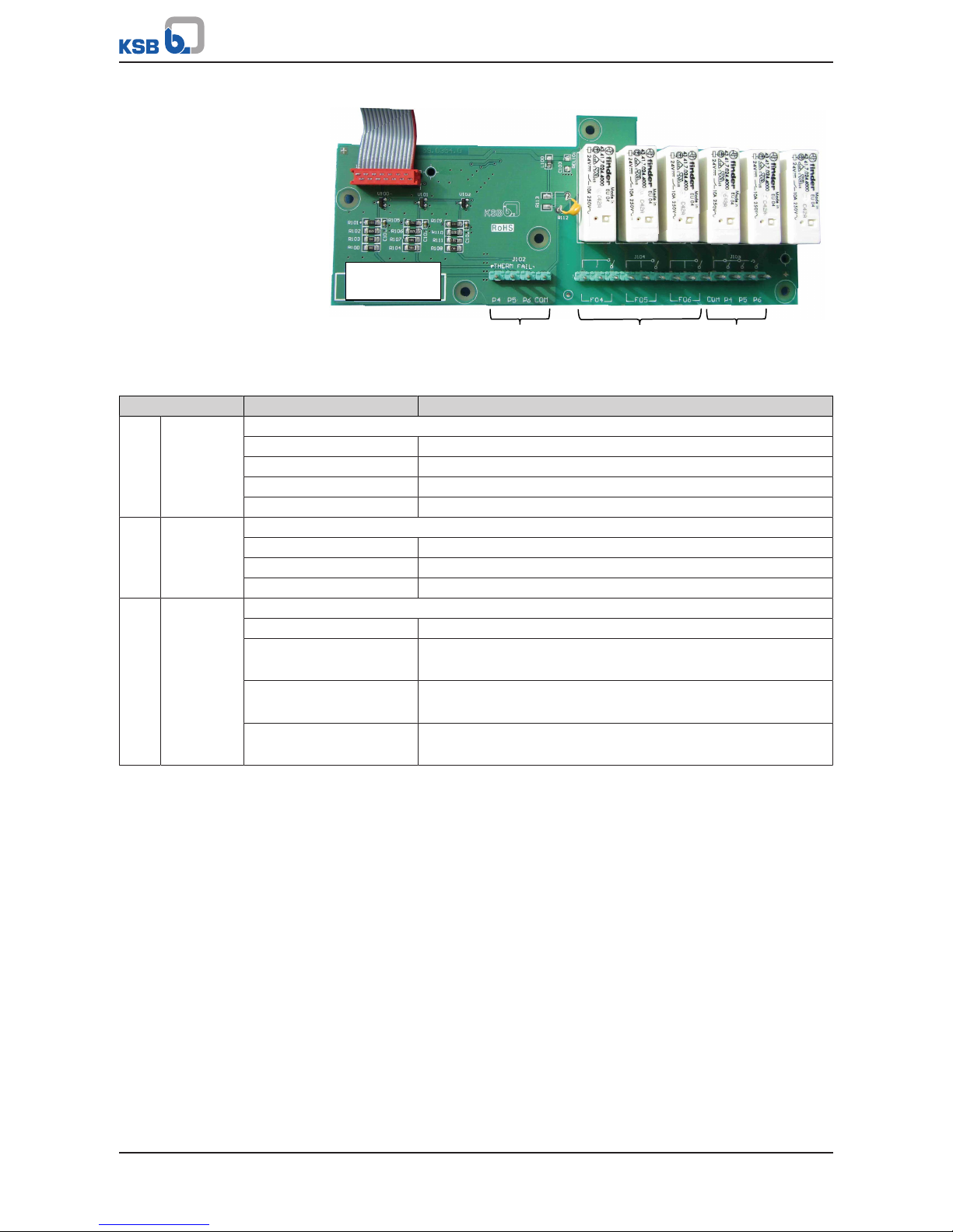
Connections on the expansion board (maximum of 6pumps)
The BoosterControl Advanced version for 6pumps is equipped with additional
terminals in the centre area at the rear of the control system (cannot be retrofitted;
factory-set).
Terminals P4 - P6 are used to connect the freely parameterisable outputs.
5 Installation at Site
17 of 88
BoosterControl Advanced
1 2 3
Fig.3: Expansion board
Table10: Additional connections on the expansion board for 6pumps with parameterisable outputs
Terminal strip Terminal Description
1 J102 Fault input, pump set
P4 Motor protection/thermal overload, pump 4
P5 Motor protection/thermal overload, pump 5
P6 Motor protection/thermal overload, pump 6
COM Digital inputs - 24 V DC supply
2 J104 Activation of frequency inverters 4 - 6
F04 Start, frequency inverter 4
F05 Start, frequency inverter 5
F06 Start, frequency inverter 6
3 J103 Pump contactors 4 - 6
COM Pump contactors - earth
P4 Contactor of pump4
Parameterisable output 1
P5 Contactor of pump5
Parameterisable output 2
P6 Contactor of pump6
Parameterisable output 3
5.4.2 Connection to power supply
1. Observe the terminal assignments on the printed circuit board.
(ðSection5.4.1,Page14)
2. Connect to power supply:
- Terminal strip J201, terminals L1, N and PE
5.4.3 Connecting/bridging the motor protection device
Connect motor protection device with safe isolation in acc. with EN50178.
Use the following terminals on the printed circuit board:
▪ Terminal strip J403, terminals P1, P2, P3 and COM
For more than 3pumps, also use the following terminals:
▪ Terminal strip J102, terminals P4 - P6 and COM
Connect/bridge the thermal circuit breaker.

5 Installation at Site
18 of 88
BoosterControl Advanced
Motors with thermal circuit breakers:
Motors with thermal circuit
breakers:
1. Ensure that the inputs/outputs are galvanically isolated from the thermal circuit
breaker inputs.
2. If thermal circuit breakers have not been safely isolated from the low-voltage
mains, decouple the signals using coupler modules.
3. Connect the thermal circuit breaker to BoosterControl Advanced.
Motors without thermal circuit breakers:
Motors without thermal
circuit breakers
1. Bridge the thermal circuit breaker connection on BoosterControl Advanced.
Observe terminal wiring diagram.
5.4.4 Connecting the pump contactors
The last two terminals can also be used as outputs for signal relays.
1. Observe the terminal assignments on the printed circuit board.
(ðSection5.4.1,Page14)
2. Connect to power supply:
- External 24 V to terminal strip J601, COM terminal
or
- 230 V from L1 terminal to terminal strip J601, COM terminal
3. Connect pump contactors:
- Terminal strip J601, terminals P1, P2, P3
4. For 6 pumps also use the following additional terminals:
- Terminal strip J103, terminals P4, P5, P6
5.4.5 Connecting the pressure sensor
1. Observe the terminal assignments on the printed circuit board.
(ðSection5.4.1,Page14)
2. If a 2-wire sensor is to be used:
- Terminal strip J404, terminals 24 V and +
3. If a 3-wire sensor is to be used:
- Terminal strip J404, terminals 24 V, + and -
5.4.6 Connecting the dry running protection device
Dry running protection can be effected by means of a pressure sensor or pressure
switch fitted on the suction side.
1. Connect the pressure sensor, if any:
- Terminal strip J405, terminals + and -
2. If available, connect pressure switch:
- Terminal strip J403, terminals RDP and COM
3. If no pressure switch is used, bridge the pressure switch terminal:
- Terminal strip J403, terminals RDP and COM
5.4.7 Other connections required depending on the operating mode
Cascade control
No further connections required.
Cascade operation with jockey pump
Ensure that the jockey pump is sized to act as a base-load pump and not as a peakload pump.
5 Installation at Site
19 of 88
BoosterControl Advanced
Floating frequency inverter
Only possible when the frequency inverter is integrated in the control cabinet.
1. Observe the logic diagram (see other applicable documents).
2. Connect frequency inverter start signal:
Terminal strip J604, terminal FO START
Fixed frequency inverter
1. Connect frequency inverter start signal to the frequency inverter of the pump to
be controlled:
- Terminal strip J604, terminal FO START, frequency inverter per pump
CAUTION
Use of different types of frequency inverter
Damage to property!
▷ Only use frequency inverters of the same type within a system!
1. Connect frequency inverter start signal:
- Terminal strip J602, terminals F01 - F03
2. For 6 pumps also use the following additional terminals:
- Terminal strip J104, terminals F04 - F06
5.4.8 Making optional connections
Some terminals must be bridged if not in use.
Bridge the following terminals if not in use:
▪ Fault reporting relay of frequency inverter: terminal strip J403, terminal TFR with
COM
▪ Fault reporting relay of valve: terminal strip J403, terminal TVA with COM
▪ External Off switch: terminal strip J403, terminal OFF with COM
▪ Fire alert: terminal strip J403, terminal FIRE with COM
The following connections can be made.
External signalling devices
The external signalling device can be powered via the BoosterControl Advanced
control unit if necessary.
1. Bridge the following connections to power the external signalling device:
Terminal strip J201, terminal L1, with terminal strip J605A or J605B, left pin
2. Connecting external signalling devices:
- For warnings, terminal strip J605A, NON URGENT terminal
- For alerts, terminal strip J605B, URGENT terminal
Water flow detection (WSD)
Up to 3water flow detectors can be connected.
1. Connect existing water flow detector:
- Terminal strip J401, terminals WS1, WS2 and WS3
2. Connect a PT1000 temperature sensor, if any:
- Terminal strip J401, terminals PT1000 - and PT1000 +
Additional information on function and configuration

5 Installation at Site
20 of 88
BoosterControl Advanced
Connections for inlet tank
ü Pump inlet pressure < 0.5bar
1. Connect pressure sensor for level monitoring:
- Observe logic diagram (refer to other applicable documents)
- Terminal strip J405, terminals +, - and 24 V
2. If a gate valve is to be used as an inlet tank valve, connect gate valve:
- Terminal strip J601, terminals VALVE and COM
3. If a proportional valve is to be used as an inlet tank valve, connect proportional
valve:
- Terminal strip J501, terminals + and -
4. If available, connect fault reporting relay of inlet tank valve:
- Terminal strip J403, terminals TVA and COM
Fault reporting relay of frequency inverter
1. Connect fault reporting relay:
- Terminal strip J403, terminals TFR and COM
External OFF switch
1. Connect external Off switch:
- Terminal strip J403, terminals OFF and COM
Fire alert
In case of a fire alert, BoosterControl Advanced starts all connected pumps at their
maximum speed.
A fire alert has absolute priority. The system cannot be stopped via the external OFF
switch.
1. Connect fire alert:
- Terminal strip J403, connect signal relay to FIRE and COM terminals
On BoosterControl Advanced, the last two terminals for pump contactors can be used
as outputs for signal relays.
1. Connect signal relay for BoosterControl Advanced version for up to 6pumps:
- Terminal strip J103, terminals P5, P6 and COM
6 Operation
21 of 88
BoosterControl Advanced
6 Operation
6.1 Control panel
1
2
3
4
5
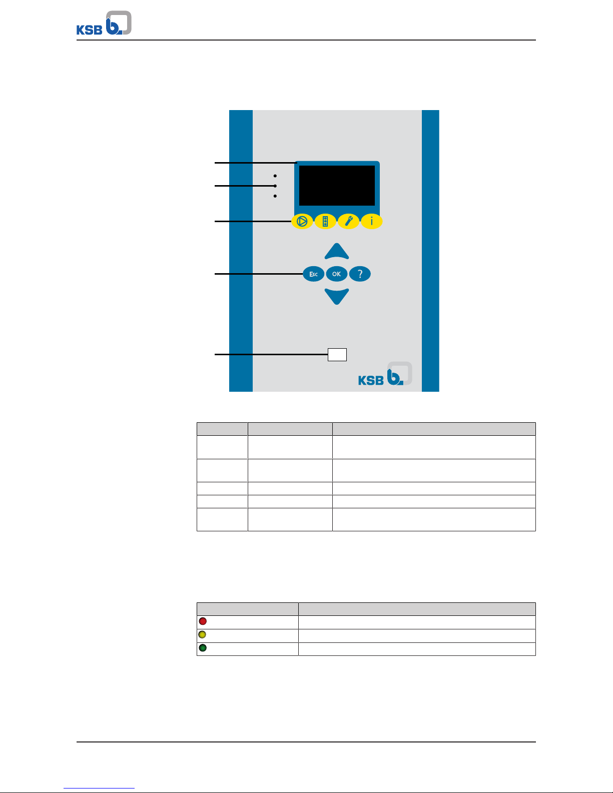
Fig.4: Control panel
Table11: Description of control panel
Item Description Function
1 Graphical display Displays information on BoosterControl Advanced
operation
2 "Traffic light" LEDs The traffic light function provides information
about the pump system's operating status.
3 Menu keys Change to the elements of the first menu level
4 Navigation keys Navigation and parameter setting
5 Service interface Configuring and parameterising BoosterControl
Advanced using a PC/notebook
6.1.1 "Traffic light" LEDs
The "traffic light" LEDs provide information about the operating status of
BoosterControl Advanced.
Table12: LED description
LED Description
Red
One or several alerts are active
Amber
One or several warnings are active
Green
Steady light: trouble-free operation
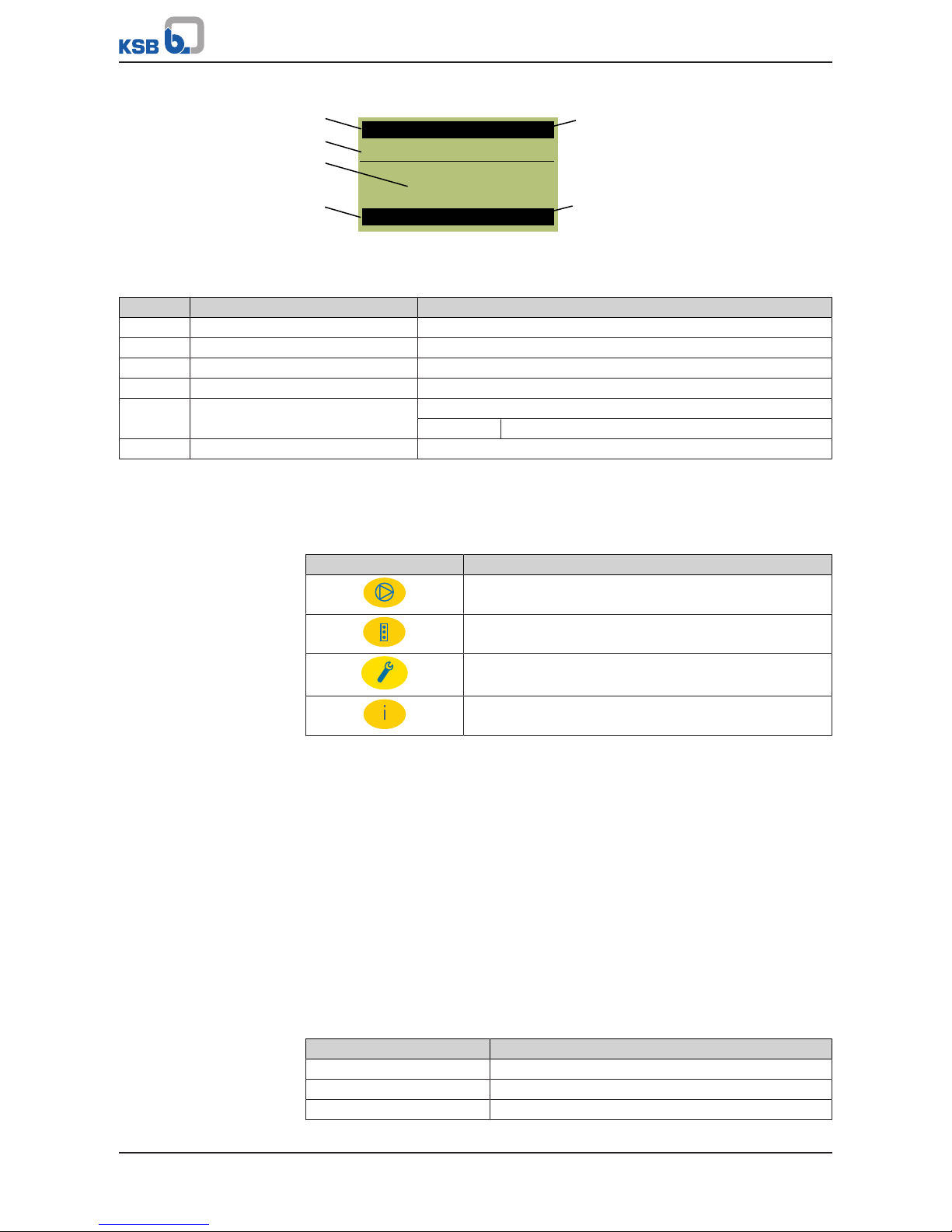
6.1.2 Graphical display
The graphical display breaks down into 6areas.
6 Operation
22 of 88
BoosterControl Advanced
3.52
12-06
bar
BC
12:37
3-5-1
Set point
Leakage
1
5
6
2
3
4
Fig.5: Graphical display (example)
Table13: Description of graphical display
Item Description Description
1 Parameter Shows the parameter selected
2 Parameter name Displays the name of the parameter selected
3 Current display Displays the current values for the parameter selected
4 Messages/alerts Displays current warning and fault messages
5 Model Displays model
BC = BoosterControl
6 Date/time Displays current date and time
6.1.3 Menu keys
You can use the menu keys to access the elements at the first menu level directly.
Table14: Assignment of menu keys
Key Menu
Operation
Diagnosis
Settings
Information
6.1.3.1 Menu: Operation
The Operation section contains all information required for operating the machine
and the process. This includes important process data (pressure, flow rate, etc.) as
well as current process states (input/output states).
The decision regarding which parameters are displayed on the main screen can be
influenced by a user who has the appropriate authorisation. The parameters to be
displayed on the main screen can be selected in the Settings menu.
6.1.3.1.1 Operating values in the start menu
A start menu can be called from the start screen following the boot procedure.
Press "OK" key when on the start screen.
The following parameters are displayed:
Table15: Parameters in start menu (depending on operating mode; here, Cascade
operating mode)
Parameter Value
3-2-1-1 PIN
3-5-1 Setpoint
3-5-3 Bandwidth
6 Operation
23 of 88
BoosterControl Advanced
Parameter Value
3-5-10 Delta p
3-5-11 High pressure alarm
3-5-13 Low pressure alarm
3-6-2 Minimum run time
3-6-5 Start delay
3-6-6 Stop delay
3-6-8 RDP delay
3-6-9 High/low alarm delay
6.1.3.2 Menu: Diagnosis
In the "Diagnosis" section, the user is provided with information about faults and
warnings that pertain to the pump set or process. This can be done with
BoosterControl Advanced in fault (system standstill) or warning (system operational)
status. The user can also find previous messages in the history.
Messages
All monitoring and protective functions trigger warnings or alerts. These are
signalled via the amber or red LED. A flashing message is output in the last line of
the control panel display. If more than one message is output, the last one is
displayed. Alerts have priority over warnings.
To display all warnings and alerts, choose the Diagnosis menu and then Active
Messages (2- 1-1). The general fault message is output via the relay outputs. .
Alert history
The alert history can be viewed under 2-1-2 after pressing the "Diagnosis" menu key.
The last 100 alerts are listed here. You can use the arrow keys and the OK key to
select an entry from the list. Information about when the alert has come and gone is
then displayed.
Acknowledging and resetting alerts
NOTE
Depending on the combination of settings, the system could conceivably restart
automatically after acknowledgement/reset or when the cause of failure has been
eliminated.
Acknowledgement
You can acknowledge the alert once the cause has been rectified. Alerts can be
acknowledged individually in the alerts list in the Diagnosis menu under (2-1-3).
Reset
All alerts are acknowledged at the same time during a reset. The reset can be carried
out via the control panel using the OK key (only possible in the start menu). You may
therefore have to press the ESC key several times to return to the start menu. The
reset can also be carried out via a digital input. Digital input 4 is defaulted for this
purpose.
Automatic reset
Alerts can also be reset automatically (3-9). Alerts and fault messages can be
configured to be reset automatically (3-9). This is only possible from the "Service"
access level.
6.1.3.2.1 Messages
All monitoring and protective functions trigger messages. BoosterControl Advanced
assigns a priority status to each message. The priority status of each message is
signalled via the amber or red LED.
If there are several messages, they are listed in order of priority.
Up to 100 messages are stored.

6 Operation
24 of 88
BoosterControl Advanced
To display current, active messages:
1. Select parameter 2-1-1.
To see more information about a message:
1. Select the message and press "OK" to confirm.
ð The status of the message is displayed (came, acknowledged, gone)
6.1.3.2.2 Displaying the alert history
The alert history is saved for future reference, even in the event of a power failure.
The alert history provides the user with a chronological log of alerts that have either
been acknowlegded or gone automatically.
1. To display the alert history:
Select parameter 2-1-2.
2. For more information on an alert:
- Select the required alert using the arrow keys.
- Press "OK" to display more information.
The following information is given for every message:
▪ Date
▪ Time
▪ Alert
▪ Status
6.1.3.2.3 Overview of warnings and alerts
Alerts, warnings and the set fault function can be assigned manually.
All warnings and alerts are listed for fault analysis.
6.1.3.3 Menu: Settings
General settings can be made or the settings for the process optimised in the Settings
section. All aspects that have to do with the operative function or availability of the
pump set can also be found here.
6.1.3.3.1 Display language
The following display languages can be toggled:
▪ German
▪ French
▪ English
▪ Dutch
▪ Turkish
Table16: Language parameter
Parameter Description Possible setting Access Factory setting
3-1-1-1 Display language German
French
English
Dutch
Turkish
Customer English
6.1.3.3.2 Access levels
Four access levels have been defined to prevent accidental or unauthorised access to
BoosterControl Advanced parameters:

6 Operation
25 of 88
BoosterControl Advanced
Table17: Access levels
Access level Description
Standard (no login) Access without password entry.
Customer Access level for the expert user with
access to all parameters required for
commissioning.
Service Access level for service personnel.
If a parameter's access level is not explicitly specified, the parameter is always
assigned the customer access level.
Table18: Access level parameter
Parameter Description Possible setting Access level required Factory
setting
3-2-1-1 Enter customer password for
access
0000...9999 Standard 0000
Enter service password for access 0000...9999 Service -
Change customer access level
password
0000...9999 Customer -
Password-protected access level
for customer parameter
Disabled
Enabled
Customer Disabled
Entering the password
Customer access level
You must enter the password under (3-2-1-1) Login to gain access. The password can
be changed under Customer Password after entering "7353" (factory password). If
password protection is deactivated via parameter 3-2-1-2, the customer access level
becomes the standard access level. This applies to the factory settings.
Service access level
You must enter a password under Service Login.
NOTE
If no keys are pressed for ten minutes, the system will automatically return to the
standard access level.
6.1.3.3.3 Displaying and changing parameters
The parameter numbers contain the navigation path, which helps you find a
particular parameter quickly and easily. The first digit of the parameter number
indicates the first menu level, which is called up directly via the four menu keys.
Table19: Assignment of menu keys
Key Menu
Operation
Diagnosis
Settings
Information
Subsequent steps are carried out via the navigation keys.
Example
Parameter 3-5-1 Setpoint
1. First digit of parameter number: 3-5-1
Press the "Settings" menu key.
ð 3-1 appears in the top left of the screen.
2. Second digit of parameter number: 3-5-1
Press the arrow key to change the display 3-1 on the screen (upper left) to 3-5.
6 Operation
26 of 88
BoosterControl Advanced
3. Press OK to confirm the selection.
ð 3-5-1 appears in the top left of the screen.
4. Press OK to confirm the selection.
ð You have called up the required parameter.
Changing the parameter value
1. Press OK.
ð The bar above the entry displays the value currently being entered.
2. Use the arrow keys to increase or decrease the value displayed.
3. Confirm the selected value by pressing OK.
ð The cursor moves to the next position (second position from the left).
4. Make the settings as described for the subsequent positions.
5. Press the OK key to save the new parameter value.
6.1.3.3.4 Access levels
Table20: Access levels
Access level Code displayed Properties
Standard - No login required
Restricted access to parameters
Customer C Login required
Access to main customer parameters
Service S Login required
Access to all service-relevant parameters
Factory F Login required
Access to all parameters
6.1.3.4 Menu: Information
All direct information about PumpDrive is provided in the Information section.
Important details regarding the firmware version are listed here.
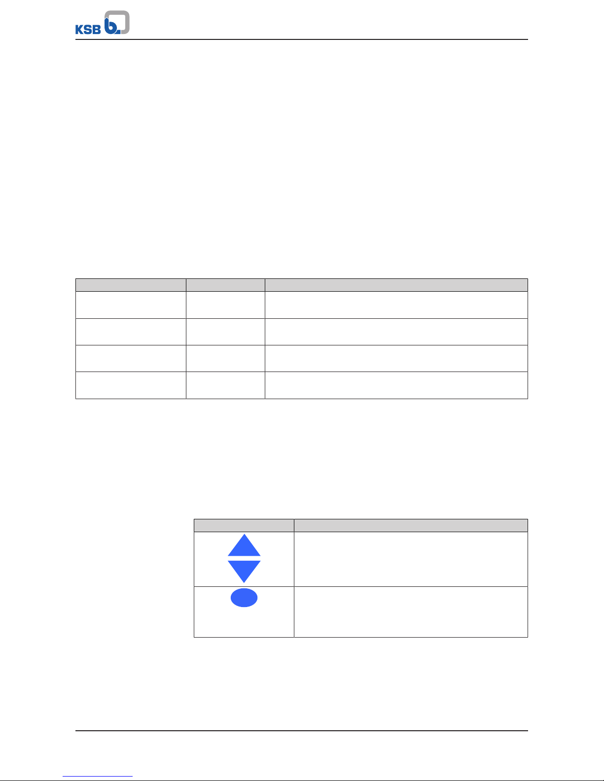
6.1.4 Navigation keys
The navigation keys are used for navigating in the menus and for confirming
settings.
Table21: Assignment of navigation keys
Key Function
Arrow keys:
▪ Move up/down in the menu options.
▪ Increase/decrease a numerical value.
Esc
Escape key:
▪ Delete/reset entry
(the entry is not saved).
▪ Move up one menu level.
6 Operation
27 of 88
BoosterControl Advanced
Key Function
OK
OK key:
▪ Confirm settings.
▪ Confirm menu selection.
▪ Move to the next digit when entering numerals.
▪ Alert reset
?
Help key:
▪ Displays a help text for each selected menu option.
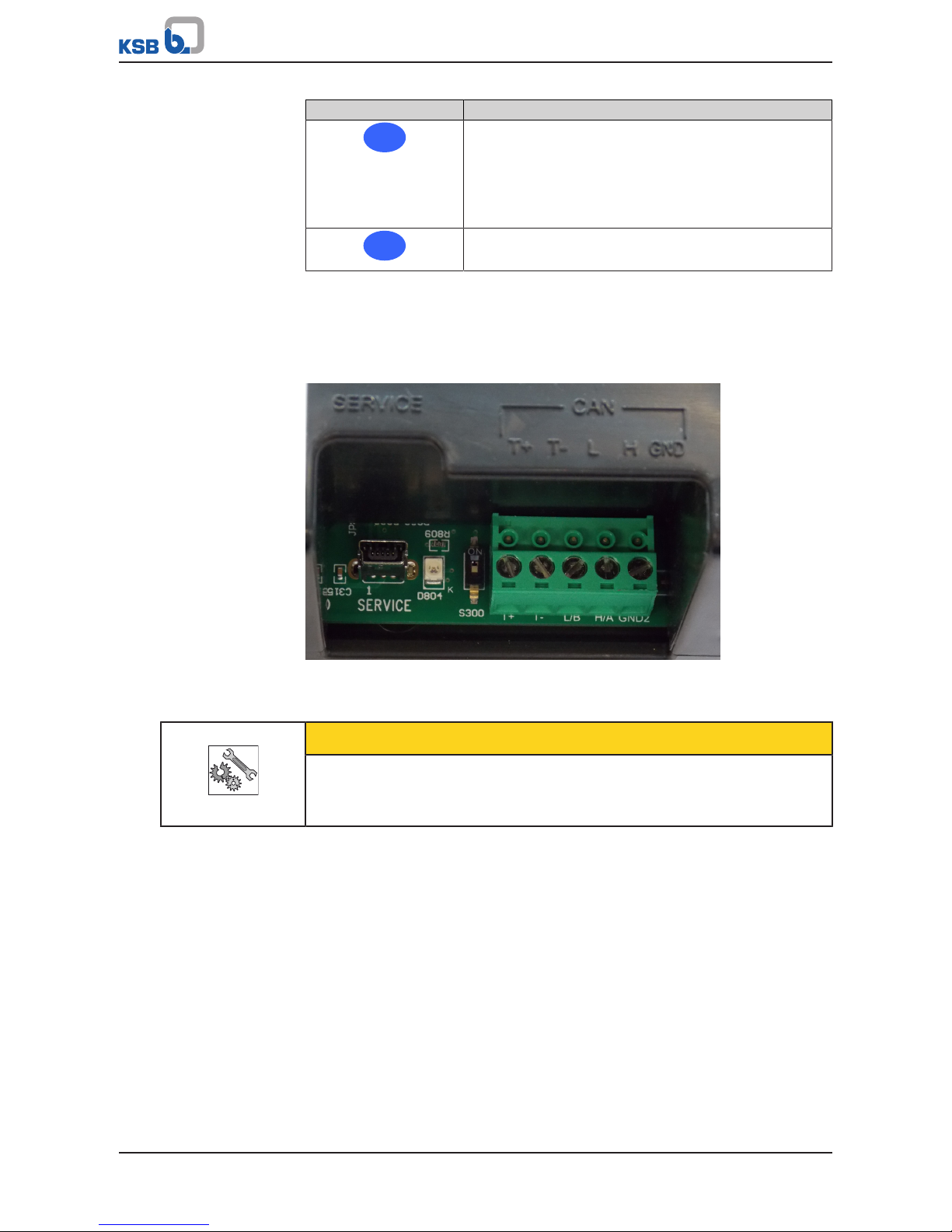
6.2 Operating the device via the service interface
Connection to the service interface can be established in two ways:
▪ Via a connector at the rear
▪ Via a connector on the control panel
Fig.6: Service interface at the rear
For details, please refer to the user manual of the "ServiceTool for BoosterControl"
Advanced.
CAUTION
Improper use of service interface
Damage to connected laptop/PC!
▷ Only use the connection cable offered by KSB (USB - RS232).
The service interface allows a PC/notebook to be connected via a special cable (USB RS232).
The following actions can be taken:
▪ Configuring and parameterising BoosterControl Advanced using the KSB service
software
▪ Software update
▪ Saving and documenting set parameters
The hardware protection (dongle) must be connected to enable the authorisation
level. Observe the service tool instructions.
6.3 Operating the device via the control panel
6.3.1 Displaying and changing parameters
The parameter number also serves as the navigation path.
The first digit of the parameter number indicates one of the following menus:
 Loading...