

Page 1
Automated Globe Valves
BOA-H Mat P
Installation/Operating Manual
Page 2

Legal information/Copyright
Installation/Operating Manual BOA-H Mat P
Original operating manual
All rights reserved. The contents provided herein must neither be distributed, copied, reproduced,
edited or processed for any other purpose, nor otherwise transmitted, published or made available to a
third party without the manufacturer's express written consent.
Subject to technical modification without prior notice.
© KSB SE & Co. KGaA, Frankenthal 15/03/2019
Page 3

Contents
Contents
Glossary .................................................................................................................................................. 5
1 General.................................................................................................................................................... 6
1.1 Principles ...........................................................................................................................................................6
1.2 Installation of partly completed machinery....................................................................................................6
1.3 Target group.....................................................................................................................................................6
1.4 Other applicable documents............................................................................................................................6
1.5 Symbols .............................................................................................................................................................6
2 Safety...................................................................................................................................................... 7
2.1 Key to safety symbols/markings.......................................................................................................................7
2.2 General..............................................................................................................................................................7
2.3 Intended use .....................................................................................................................................................8
2.4 Personnel qualification and training...............................................................................................................8
2.5 Consequences and risks caused by non-compliance with this manual .........................................................8
2.6 Safety awareness ..............................................................................................................................................9
2.7 Safety information for the operator/user.......................................................................................................9
2.8 Safety information for maintenance, inspection and installation ................................................................9
2.9 Unauthorised modes of operation..................................................................................................................9
3 Transport/Temporary Storage/Disposal............................................................................................. 10
3.1 Checking the condition upon delivery..........................................................................................................10
3.2 Transport.........................................................................................................................................................10
3.3 Storage/preservation......................................................................................................................................10
3.4 Return to supplier...........................................................................................................................................11
3.5 Disposal ...........................................................................................................................................................12
4 Valve Description ................................................................................................................................. 13
4.1 General description ........................................................................................................................................13
4.2 Marking...........................................................................................................................................................13
4.3 Name plate......................................................................................................................................................14
4.4 Design details..................................................................................................................................................14
4.5 Function ..........................................................................................................................................................15
4.6 Scope of supply...............................................................................................................................................16
4.7 Noise characteristic.........................................................................................................................................16
5 Installation at Site................................................................................................................................ 17
5.1 General information/Safety regulations .......................................................................................................17
5.2 Installation position........................................................................................................................................17
5.3 Preparing the valve ........................................................................................................................................18
5.4 Piping ..............................................................................................................................................................19
5.5 Insulation ........................................................................................................................................................19
6 Commissioning/Start-up/Shutdown................................................................................................... 21
6.1 Commissioning/start-up .................................................................................................................................21
6.2 Operating limits..............................................................................................................................................22
6.3 Shutdown........................................................................................................................................................23
6.4 Returning to service .......................................................................................................................................23
7 Servicing/Maintenance........................................................................................................................ 24
7.1 Safety regulations...........................................................................................................................................24
7.2 Maintenance/inspection.................................................................................................................................25
7.3 Dismantling the valve.....................................................................................................................................26
7.4 Assembling the valve......................................................................................................................................28
7.5 Tightening torques.........................................................................................................................................30
BOA-H Mat P
3 of 40
Page 4

Contents
8 Trouble-shooting.................................................................................................................................. 31
9 Related Documents.............................................................................................................................. 32
9.1 General assembly drawing with list of components ....................................................................................32
9.2 Maximum permissible closing pressures .......................................................................................................33
9.3 Dimensions and weights of BOA-HMatP globe valve ................................................................................33
9.4 Dimensions and weights of actuator ............................................................................................................34
10 EU Declaration of Conformity for BOA-H Mat E, BOA-HMatP........................................................ 35
11 Certificate of Decontamination........................................................................................................... 36
Index ..................................................................................................................................................... 37
4 of 40
BOA-H Mat P
Page 5

Glossary
Glossary
Certificate of decontamination
A certificate of decontamination is enclosed by the
customer when returning the product to the
manufacturer to certify that the product has been
properly drained to eliminate any environmental
and health hazards arising from components in
contact with the fluid handled.
Pressure Equipment Directive (PED)
The 2014/68/EU Directive sets out the
requirements to be met by pressure equipment
intended to be placed on the market in the
European economic area.
BOA-H Mat P
5 of 40
Page 6
1 General
1 General
1.1 Principles
This operating manual is valid for the type series and variants indicated on the front
cover.
The operating manual describes the proper and safe use of this equipment in all
phases of operation.
The name plate indicates the type series and size, the main operating data, the order
number and the order item number. The order number and order item number
uniquely identify the valve and serve as identification for all further business
processes.
In the event of damage, immediately contact your nearest KSB sales organisation
responsible to maintain the right to claim under warranty.
1.2 Installation of partly completed machinery
To install partly completed machinery supplied by KSB refer to the sub-sections under
Installation at Site. (ðSection5,Page17)
1.3 Target group
This operating manual is aimed at the target group of trained and qualified specialist
technical personnel.
1.4 Other applicable documents
Table1: Overview of other applicable documents
Document Contents
Type series booklet Description of the technical data of the valve
Actuator operating manual Proper and safe use of the actuator in all phases
of operation
Flow characteristics
General assembly drawing
1)
2)
Information on Kv and zeta values
Sectional drawing of the valve
Sub-supplier product literature3)Operating manuals and other product literature
for the accessories
Observe the relevant manufacturer's product literature for the accessories.
1.5 Symbols
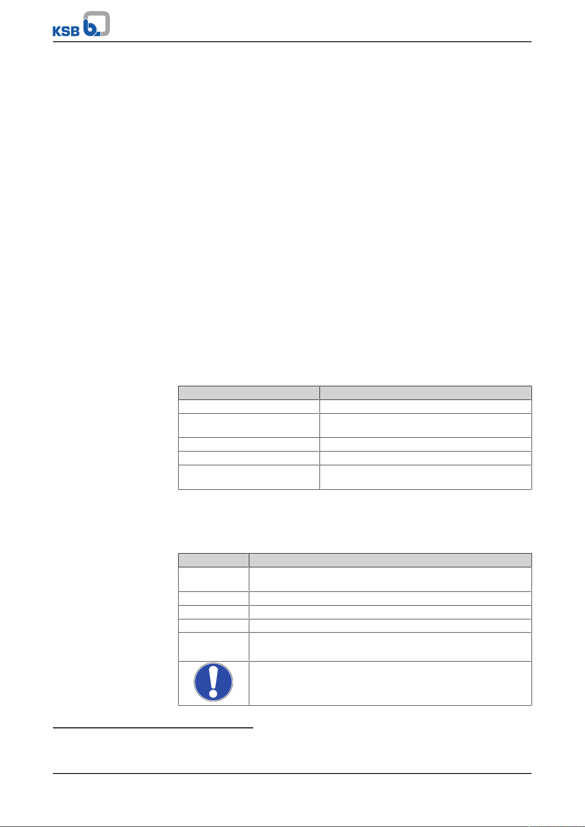
Table2: Symbols used in this manual
Symbol Description
✓ Conditions which need to be fulfilled before proceeding with the
step-by-step instructions
⊳ Safety instructions
⇨
⇨ Cross-references
1.
2.
Result of an action
Step-by-step instructions
Note
Recommendations and important information on how to handle
the product
1) If any
2) If inclusion in the scope of supply has been agreed; otherwise refer to the type series booklet.
3) If inclusion in the scope of supply has been agreed.
6 of 40
BOA-H Mat P
Page 7
2 Safety
!
DANGER
!
DANGER
!
WARNING
CAUTION
2 Safety
All the information contained in this section refers to hazardous situations.
In addition to the present general safety information the action-related safety
information given in the other sections must be observed.
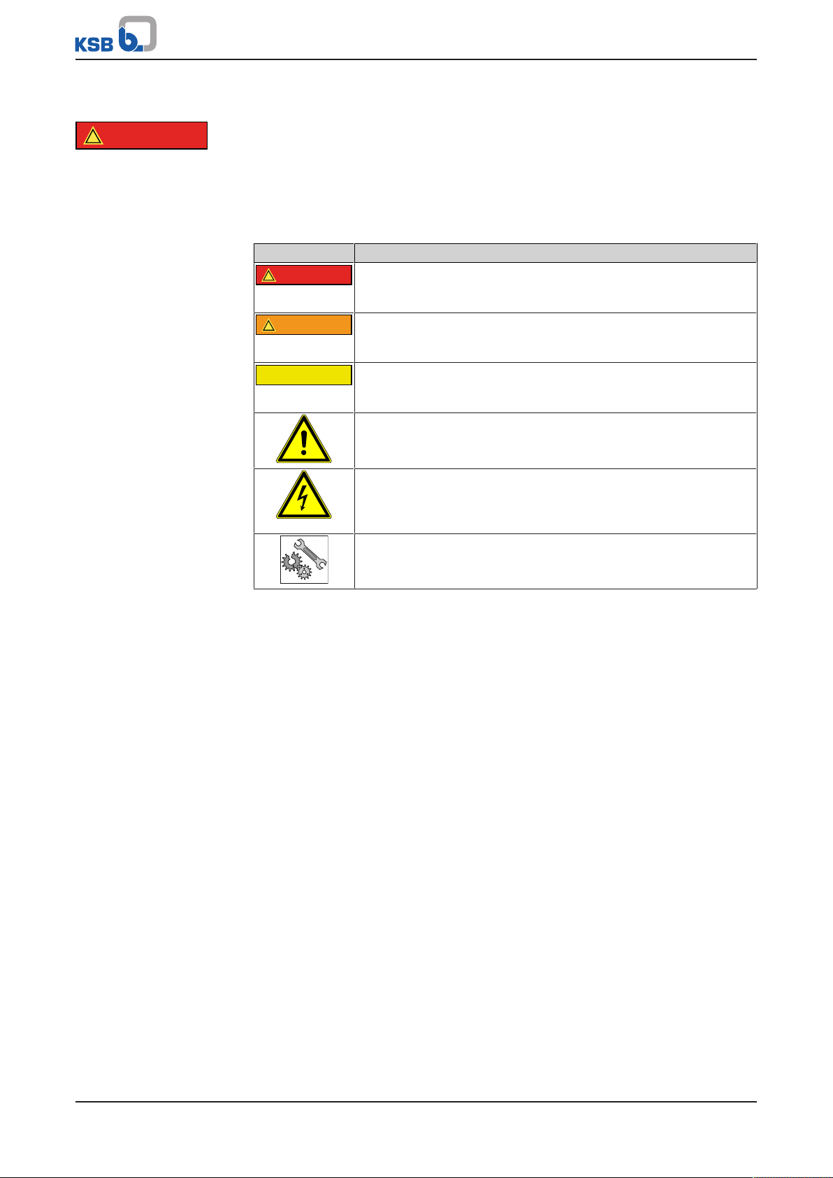
2.1 Key to safety symbols/markings
Table3: Definition of safety symbols/markings
Symbol Description
DANGER
This signal word indicates a high-risk hazard which, if not avoided,
will result in death or serious injury.
WARNING
This signal word indicates a medium-risk hazard which, if not
avoided, could result in death or serious injury.
CAUTION
This signal word indicates a hazard which, if not avoided, could
result in damage to the machine and its functions.
General hazard
In conjunction with one of the signal words this symbol indicates a
hazard which will or could result in death or serious injury.
Electrical hazard
In conjunction with one of the signal words this symbol indicates a
hazard involving electrical voltage and identifies information about
protection against electrical voltage.
Machine damage
In conjunction with the signal word CAUTION this symbol indicates
a hazard for the machine and its functions.
2.2 General
▪ This operating manual contains general installation, operating and maintenance
instructions that must be observed to ensure safe operation of the system and
prevent personal injury and damage to property.
▪ Comply with all the safety instructions given in the individual sections of this
operating manual.
▪ The operating manual must be read and understood by the responsible specialist
personnel/operators prior to installation and commissioning.
▪ The contents of this operating manual must be available to the specialist
personnel at the site at all times.
▪ Information and markings attached directly to the product must always be
complied with and kept in a perfectly legible condition at all times. This applies
to, for example:
– Flow direction arrow
– Name plate
– Valve body material
▪ The operator is responsible for ensuring compliance with all local regulations not
taken into account.
▪ The design, manufacture and testing of the valve are subject to a QM system to
DINENISO9001 as well as the current European Pressure Equipment Directive.
▪ Bear in mind that valves exposed to creep-rupture conditions have a limited
service life and have to meet the applicable regulations stipulated in the
technical codes.
BOA-H Mat P
7 of 40
Page 8

2 Safety
▪ In the case of customised special variants, further restrictions may apply with
regard to the operating mode and service life. Refer to the relevant sales
documentation for applicable limitations.
▪ The operator is responsible for ensuring compliance with all local regulations not
taken into account.
▪ The operator is responsible for any eventualities or incidents which may occur
during installation performed by the customer, operation and maintenance.
2.3 Intended use
▪ Only operate valves and actuators which are in perfect technical condition.
▪ Do not operate partially assembled valves or actuators.
▪ Only use the valve for fluids specified in the product literature. Take the design
and material variant into account.
▪ Only operate the valve within the operating limits described in the other
applicable documents.
▪ Only operate the actuator within the permissible ambient temperature limits.
▪ Consult the manufacturer about any other modes of operation not described in
the product literature.
▪ Do not use the valve or actuator as a foothold.
2.3.1 Prevention of foreseeable misuse
▪ Never exceed the permissible application and operating limits specified in the
product literature regarding pressure, temperature, etc.
▪ Observe all safety information and instructions in this manual.
2.4 Personnel qualification and training
▪ All personnel involved must be fully qualified to transport, install, operate,
maintain and inspect the product this manual refers to and be fully aware of the
interaction between the valve and the system.
▪ The responsibilities, competence and supervision of all personnel involved in
transport, installation, operation, maintenance and inspection must be clearly
defined by the operator.
▪ Deficits in knowledge must be rectified by means of training and instruction
provided by sufficiently trained specialist personnel. If required, the operator can
commission the manufacturer/supplier to train the personnel.
▪ Hands-on training at the valve and the actuator must always be supervised by
specialist technical personnel.
2.5 Consequences and risks caused by non-compliance with this manual
▪ Non-compliance with these operating instructions will lead to forfeiture of
warranty cover and of any and all rights to claims for damages.
▪ Non-compliance can, for example, have the following consequences:
– Hazards to persons due to electrical, thermal, mechanical and chemical
effects and explosions
– Failure of important product functions
– Failure of prescribed maintenance and servicing practices
– Hazard to the environment due to leakage of hazardous substances
8 of 40
BOA-H Mat P
Page 9

2 Safety
2.6 Safety awareness
In addition to the safety information contained in this operating manual and the
intended use, the following safety regulations shall be complied with:
▪ Accident prevention, health regulations and safety regulations
▪ Explosion protection regulations
▪ Safety regulations for handling hazardous substances
▪ Applicable standards, directives and laws
2.7 Safety information for the operator/user
Actuator-operated valves are intended for use in areas which cannot be accessed by
unauthorised persons. Operation of these valves in areas which can be accessed by
unauthorised persons is only permitted if appropriate protective devices are fitted at
the site. This must be ensured by the operator.
▪ Fit protective equipment (e.g. contact guards) supplied by the operator for hot,
cold or moving parts, and check that the equipment functions properly.
▪ Do not remove any protective equipment (e.g. contact guards) during operation.
▪ Provide the personnel with protective equipment and make sure it is used.
▪ Contain any leakage of hazardous fluids (e.g. explosive, toxic, hot) so as to avoid
any danger to persons and the environment. Adhere to all relevant laws.
▪ Eliminate all electrical hazards. (In this respect refer to the applicable national
safety regulations and/or regulations issued by the local energy supply
companies.)
2.8 Safety information for maintenance, inspection and installation
▪ Modifications or alterations of the valve require the manufacturer's prior
consent.
▪ Use only original spare parts or parts/components authorised by the
manufacturer. The use of other parts/components can invalidate any liability of
the manufacturer for resulting damage.
▪ The operator ensures that maintenance, inspection and installation are
performed by authorised, qualified specialist personnel who are thoroughly
familiar with the manual.
▪ Only carry out work on the valve during standstill of the entire system.
▪ The valve body must have cooled down to ambient temperature.
▪ The pressure in the valve body must have been released and the valve must have
been drained.
▪ When taking the valve out of service always adhere to the procedure described
in the manual.
▪ The actuator must be disconnected from the external source of energy.
▪ Decontaminate valves which handle fluids posing a health hazard.
▪ Protect the valve body and body bonnet/cover from any impacts.
▪ As soon as the work has been completed, re-install and re-activate any safety-
relevant devices and protective devices. Before returning the product to service,
observe all instructions on commissioning.
2.9 Unauthorised modes of operation
Never operate the automated globe valve outside the limits stated in the operating
manual.
The warranty relating to the operating reliability and safety of the automated globe
valve supplied is only valid if the valve is used in accordance with its intended use .
BOA-H Mat P
9 of 40
Page 10
3 Transport/Temporary Storage/Disposal
3 Transport/Temporary Storage/Disposal
3.1 Checking the condition upon delivery
1. On transfer of goods, check each packaging unit for damage.
2. In the event of in-transit damage, assess the exact damage, document it and
notify KSB or the supplying dealer and the insurer about the damage in writing
immediately.
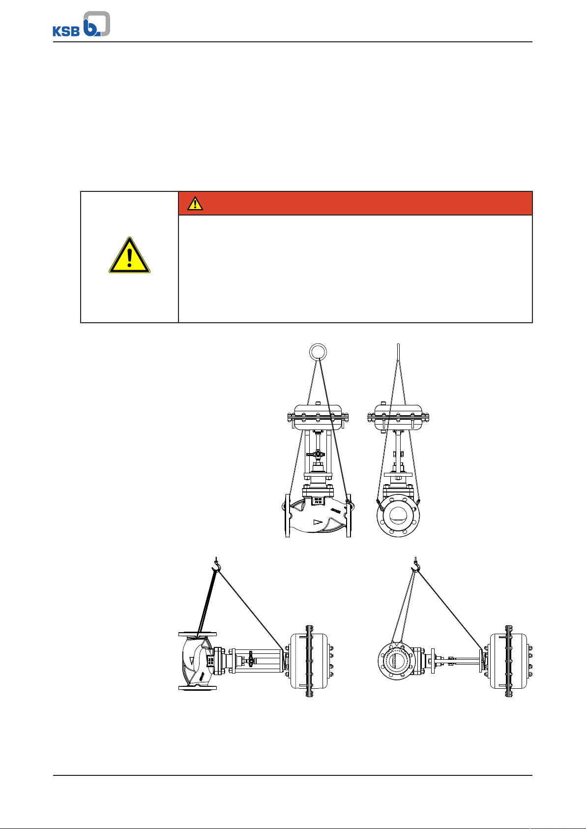
3.2 Transport
DANGER
The valve/actuator unit could slip out of the suspension arrangement.
Danger to life from falling parts!
▷ Only transport the valve/actuator unit in the specified position.
▷ Never attach lifting accessories to the actuator.
▷ Observe the information on weights, centre of gravity and fastening points.
▷ Observe the applicable local accident prevention regulations.
▷ Use suitable, permitted lifting accessories, e.g. self-tightening lifting tongs.
To transport the valve, suspend it from the lifting tackle as illustrated.
10 of 40
Fig.1: Transporting a valve with pneumatic actuator
3.3 Storage/preservation
If commissioning is to take place some time after delivery, we recommend that the
following measures be taken for storing the valve:
BOA-H Mat P
Page 11
3 Transport/Temporary Storage/Disposal
CAUTION
Damage due to frost, humidity or dirt
Corrosion/contamination of the valve!
▷ Store the valve in a dry, dust-free and vibration-free, frost-proof room where
the atmospheric humidity is as constant as possible.
▷ Protect the valve against contamination, e.g. with suitable caps or film.
CAUTION
Damage due to excessive valve closing force
Damage to the seat/disc interface!
▷ Store the valve in the closed position.
▷ For soft-seated valves, ensure that the valve is closed using little force only. This
will prevent premature cold flow (compression set) of the thermoplastic
material.
Storage and/or temporary storage of the valves must ensure that even after a
prolonged period of storage the valves’ function is not impaired.
The temperature in the storage room must not exceed +40°C.
Cover the actuators to protect them from dust and dirt, and protect them from
mechanical damage.
If properly stored indoors, the equipment is protected for a maximum of 12months.
New valves are supplied by our factory duly prepared for storage.
For storing a valve which has already been operated, observe the measures to be
taken for shutdown. (ðSection6.3,Page23)
3.4 Return to supplier
1. Drain the valve as described in the manual.
2. Flush and clean the valve, particularly if it has been used for handling noxious,
explosive, hot or other hazardous fluids.
3. If the valve has handled fluids whose residues could lead to corrosion damage in
the presence of atmospheric humidity or could ignite upon contact with oxygen
also neutralise the valve and blow through with anhydrous inert gas to ensure
drying.
4. When returning valves used for handling Fluids in Group1 always complete and
enclose a certificate of decontamination.
Indicate any safety measures and decontamination measures taken.
NOTE
If required, a blank certificate of decontamination can be downloaded from the
following web site: www.ksb.com/certificate_of_decontamination
BOA-H Mat P
11 of 40
Page 12

3 Transport/Temporary Storage/Disposal
3.5 Disposal
WARNING
Fluids handled, consumables and supplies which are hot or pose a health hazard
Hazard to persons and the environment!
▷ Collect and properly dispose of flushing fluid and any residues of the fluid
handled.
▷ Wear safety clothing and a protective mask if required.
▷ Observe all legal regulations on the disposal of fluids posing a health hazard.
1. Dismantle the valve.
Collect greases and other lubricants during dismantling.
2. Separate and sort the valve materials, e.g. by:
- Metals
- Plastics
- Electronic waste
- Greases and other lubricants
3. Dispose of materials in accordance with local regulations or in another
controlled manner.
12 of 40
BOA-H Mat P
Page 13

4 Valve Description
PN DN
≤25 32 40 50 65 80 100 125 150 ≥200
10
16
25
≥40
4 Valve Description
4.1 General description
▪ Automated globe valve with pneumatic actuator
Valve for shutting off fluids in industrial plant, process engineering, plant
engineering, cooling circuits and heating systems.
4.2 Marking
Table4: General marking
Parameter Values
Nominal size DN ...
Nominal pressure class PN ...
Manufacturer KSB
Type series/Model BOA-...
Year of construction 20..
Material .......
Flow direction arrow →
Traceability of the material .......
CE marking
Fluids in Groups 1 and 2
Fluid groups In accordance with Article13 Para.1 of the European Pressure Equipment Directive
Identification number of the notified body 0036
Customer's marking e.g. plant/system No., etc.
Factory marking Inspector’s stamp mark on the
flange following the successful
final inspection and testing of
the valve
In accordance with the current European Pressure Equipment Directive (PED) the
valves are marked as shown in the following table:
Fig.2: Fluids in Groups 1 and 2
(PED) 2014/68/EU, Group1 comprises all fluids posing physical or health hazards, e.g.
fluids defined asFluids in Group 1
▪ Explosive
▪ Extremely flammable
▪ Highly flammable
▪ Very toxic
▪ Toxic
▪ Oxidising
Group 2 comprises all other fluids not referred to in Group 1.
BOA-H Mat P
13 of 40
Page 14

4 Valve Description
PA-N Antrieb
Auftrag / Pos.:
orderNo. / pos.:
2120000000 / 0000
Max. Betriebsdruck
lowable operating pressure
6 bar
Funktion
operation
Feder schließt
Federanzahl:
number ofs prings:
4
Antrieb:
actuator:
PA-N xxx IP67
Federbereich:
spring range:
1,7 - 2,7 bar
1 2 3
4 5 6 7 8 9
Name der Baureihe (pneum.)
Auftrag / Pos.:
orderNo. / pos.:
2120000000 / 0000
Kvs:
...
Stellort / TAG-Nr. ......................
Stellhub:
stroke:
.... mm
DN
PN
...
Kennlinie:
characteristic:
...........
PTFE:
Tmax.250 °C
1 2 3
4 5 6 7 8 9 10 11 12
4.3 Name plate
Fig.3: Actuator name plate (example)
1 Order number 2 Order item number
3 Product name 4 Spring range
5 Maximum operating pressure 6 Number of springs
7 Function 8 Actuator size
9 Enclosure
Fig.4: Valve name plate (example)
1 Order number 2 Order item number
3 Product name 4 Nominal pressure class
5 Nominal size (DN) 6 Kvs value
7 Characteristic curve 8 Actuator stroke
9 Point of control 10 Tag number
11 Stem seal 12 Maximum application temperature
[°C]
4.4 Design details
Design
Globe valve:
▪ Straight-way pattern with horizontal seat
▪ Throttling plug ≤DN100
▪ On/off disc ≥DN125
▪ Spring-loaded PTFE V-packing ≤250°C
▪ Graphite gland packing ≤350°C
▪ Flanges to DIN EN 1092-2 Type 21
▪ Leakage rateA
▪ Exterior coating: blue,RAL5002
▪ The valves satisfy the safety requirements of AnnexI of the European Pressure
Equipment Directive2014/68/EU (PED) for fluids in Groups1and2.
14 of 40
BOA-H Mat P
Page 15

4 Valve Description
411
350
200
161
100
461
Actuators (technical data refers to basic configuration):
▪ Spring-to-close or air-to-close design (on request)
Max. control pressure 6bar
Mechanical or inductive limit switches
Variants
Globe valve:
▪ Valve disc with PTFE gasket (≤200°C)
▪ Other flange designs
▪ High-temperature resistant paint (grey aluminium)
▪ Certification to customer specification
4.5 Function
Fig.5: Sectional drawing
100 Body 161 Body bonnet
200 Stem 350 Valve disc
411 Bonnet gasket 461 Stem seal
Design The automated globe valve with pneumatic actuator consists of the pressure-
retaining parts, i.e. body 100 and body bonnet 161, and the functional unit (stem 200
and valve disc 350).
Function The valve is operated by a pneumatic actuating element (actuator).
Sealing Body 100 and body bonnet 161 are joined by studs 902, and the joint is sealed to
atmosphere by joint ring 411.
On the standard valve design, the passage of stem 200 is sealed by means of either a
PTFE V-packing or a graphite gland packing 461. The PTFE V-packing stem seal is
maintenance-free.
BOA-H Mat P
15 of 40
Page 16

4 Valve Description
4.6 Scope of supply
The following items are included in the scope of supply:
▪ Automated globe valve
▪ Valve operating manual
▪ Actuator operating manual
4.7 Noise characteristic
When operated within the operating conditions documented in the order
confirmation and/or characteristic curves booklets, the valve will not exceed a sound
pressure level of 80dB in acc. with IEC60534-8-4. Unfavourable piping layouts or offdesign operating conditions may give rise to physical phenomena like cavitation,
resulting in significantly higher sound pressure levels.
16 of 40
BOA-H Mat P
Page 17

5 Installation at Site
5 Installation at Site
5.1 General information/Safety regulations
The consultant, construction company or operator are responsible for positioning
and installing the valves. Planning errors and installation errors may impair the
reliable function of the valves and pose a substantial safety hazard.
WARNING
Damage to pressure enclosure or add-on parts
Leakage from or rupture of the valve
Valve/add-on parts not functional
▷ Check the valve for in-transit damage prior to installation.
▷ Check any add-on parts for in-transit damage.
▷ Do not install damaged valves.
CAUTION
Welding in close proximity to soft-seated valves
Damage to the seat/disc interface!
▷ Ensure that the valve is not heated beyond the specified temperature limits.
(ðSection6.2,Page22)
5.2 Installation position
WARNING
Installation of the valve with the stem pointing downwards
Damage to the valve!
▷ Install the valve with the stem pointing upwards or to the side.
▷ Observe the permissible installation position.
CAUTION
Actuators installed in an inclined position of 30° or more off the vertical
No valve function!
▷ Support actuators > 13kg.
BOA-H Mat P
17 of 40
Page 18

5 Installation at Site
Fig.6: PA-N300 to PA-N540
Install the actuator with sufficient clearance for removal.
NOTE
For the valves to reach the documented Kv values, the flow direction must
correspond to the flow direction arrow.
5.3 Preparing the valve
CAUTION
Outdoor installation
Damage due to corrosion!
▷ Provide weather-proof protection to protect the valve against moisture.
1. Thoroughly clean, flush and blow through all vessels, piping and connections.
2. Remove the valve's flange covers before installing it in the piping.
3. Check that the inside of the valve is free from any foreign objects. Remove any
foreign objects.
4. If required, install a strainer in the piping.
18 of 40
BOA-H Mat P
Page 19

5 Installation at Site
5.4 Piping
WARNING
Impermissible piping forces
Leakage from or rupture of the valve body!
▷ Connect the pipes to the valve without transmitting any stresses or strains.
▷ Take constructional measures to prevent any piping forces from being
transmitted to the valve.
CAUTION
Painting pipes and actuator
Valve function impaired!
▷ Protect stem, plastic components and actuator elements prior to applying paint.
5.4.1 Flanged connection
Fasteners Only use fasteners (e.g. to DINEN1515-4) and flange gaskets (e.g. to DINEN1514)
made of materials approved for the respective nominal valve size. Always use all
flange bolt holes provided when connecting the valve to the pipe.
Flanged connection
NOTE
Exception: DN 65 PN 16
When using steel flanges to DINEN1092-1 in conjunction with cast iron valves with
flanges machined to DINEN1092-2, ensure that for nominal size DN65 classed
PN16 the mating flanges are fitted offset by 22.5°.
DN65 PN10/16 (steel/steel):
DINEN1092-1 with DINEN1092-1: bolts
through 8holes
ü The mating flange faces are clean and undamaged.
1. Use an appropriate tool to evenly tighten the fasteners crosswise.
5.5 Insulation
DN65 PN10/16 (steel/cast iron):
DINEN1092-1 with DINEN1092-2: bolt
hole circle to DINEN1092-1 rotated by
22.5°, bolts through 4holes, 4holes free
WARNING
Cold/hot piping and/or valve
Risk of thermal injury!
▷ Insulate the valve.
▷ Fit warning signs.
BOA-H Mat P
19 of 40
Page 20

5 Installation at Site
CAUTION
Condensation forming in air-conditioning systems, cooling systems and
refrigerating systems
Ice forming!
Actuating element blockage!
Damage due to corrosion!
▷ Insulate the valve to prevent diffusion.
20 of 40
BOA-H Mat P
Page 21

6 Commissioning/Start-up/Shutdown
6 Commissioning/Start-up/Shutdown
6.1 Commissioning/start-up
CAUTION
Welding beads, scale and other impurities in the piping
Damage to the valve!
▷ Remove any impurities from the piping, e.g. by flushing the pipe with the valve
in fully open position.
▷ If necessary, install a strainer.
DANGER
All work performed on the actuator:
Risk of injury!
▷ Observe the actuator’s operating manual.
6.1.1 Prerequisites for commissioning/start-up
Before commissioning/start-up of the valve, ensure that the following requirements
are met:
▪ The material, pressure data and temperature data of the valve are compatible
with the operating conditions of the piping.
▪ The material's chemical resistance and stability under load have been checked.
DANGER
Surge pressure/water hammer potentially occurring at high temperatures
Danger to life caused by burns or scalds!
▷ Do not exceed the valve's maximum permissible pressure.
▷ Use valves made of nodular cast iron or steel.
▷ The operator shall provide general safety measures for the system.
6.1.2 Actuation/operation
The valve is operated by means of a pneumatic actuator.
WARNING
Improper handling of pneumatic actuator
Crushing of fingers!
Damage to the actuator or the valve!
▷ Ensure that any objects and parts of the body are removed from the actuator
coupling area prior to starting the actuator.
CAUTION
Impermissible system parameters
Excessive wear and/or damage to the valve by vibration and cavitation!
▷ Change the system parameters.
▷ Consult KSB if special solutions need to be selected.
BOA-H Mat P
21 of 40
Page 22

6 Commissioning/Start-up/Shutdown
6.1.3 Functional check
Visual inspection The following functions must be checked:
After the valve has been subjected to load conditions or heated up for the first time
check the joint between the body and the bonnet/cover established by bolting
902/920 and joint ring 411 for tightness.
If leakage occurs or bonnet/cover bolting 902/920 is loose, evenly re-tighten it
crosswise. (ðSection7.5,Page30)
DANGER
Failure to re-tighten bonnet/cover bolting after first loading
Leakage of hot and/or toxic fluids!
▷ Re-tighten bonnet/cover bolting 902/920 of valves operated at temperatures
exceeding 200°C.
6.2 Operating limits
6.2.1 Ambient temperature
Observe the following parameters and values during operation:
Table5: Permissible ambient temperatures
Ambient condition Value
Ambient temperature -10°C to +60°C
Humidity 5 % to 95 % rH
6.2.2 Pressure/temperature ratings
Table6: Test pressure and operating pressure
PN Material Shell test Leak test (seat) Permissible operating pressure
With water
Tests P10 and P11 to
DINEN12266-1
Test P12, leakage rate A
to DINEN12266-1
[bar] [bar] -10 to
[bar]
[°C]
4)5)
200 250 300 350
+120
16 EN-GJS-400-18-LT 24 ∆p 16 14,7 13,9 12,8 11,2
25 EN-GJS-400-18-LT 37,5 ∆p 25 23 21,8 20 17,5
4) Intermediate temperatures can be derived by linear interpolation.
5) Static load
22 of 40
BOA-H Mat P
Page 23

6 Commissioning/Start-up/Shutdown
6.3 Shutdown
6.3.1 Measures to be taken for shutdown
During prolonged shutdown periods, ensure that the following conditions are met:
1. Drain fluids which change their physical condition due to changes in
concentration, polymerisation, crystallisation, solidification, etc. from the piping.
2. If required, flush the piping with the valves fully opened.
3. Shut down the pneumatic actuator as specified in the actuator's operating
manual.
6.4 Returning to service
For returning the equipment to service, observe the sections on commissioning/startup and the operating limits (ðSection6.2,Page22) .
In addition, carry out all servicing/maintenance operations before returning the valve
to service. (ðSection7,Page24)
BOA-H Mat P
23 of 40
Page 24

7 Servicing/Maintenance
7 Servicing/Maintenance
7.1 Safety regulations
DANGER
Valve under pressure
Risk of injury!
Leakage of hot and/or toxic fluids!
Risk of burns!
▷ The valve and its surrounding system must be depressurised prior to any
maintenance work and installation work.
▷ If the bellows are defective and fluid escapes, depressurise the valve.
▷ Ensure the valve is depressurised before removing any drain plugs, opening
plugs or vent plugs.
▷ Allow the valve to cool down so that the temperature is below the fluid's
vaporisation temperature in all areas in contact with the fluid in order to
effectively prevent any risk of scalding.
▷ Never vent the valve by removing the bonnet/cover bolting or gland packing.
▷ Use appropriate spare parts and tools, even in emergencies.
The operator ensures that maintenance, inspection and installation are performed by
authorised, qualified specialist personnel who are thoroughly familiar with the
manual.
WARNING
Fluids handled, consumables and supplies which are hot and/or pose a health
hazard
Risk of injury!
▷ Observe all relevant laws.
▷ When draining the fluid take appropriate measures to protect persons and the
environment.
▷ Decontaminate valves used in fluids posing a health hazard.
WARNING
Actuator parts moving due to pre-loaded springs when auxiliary energy supply
fails
Risk of injury!
▷ Observe the actuator’s operating manual.
A regular maintenance schedule will help avoid expensive repairs and contribute to
trouble-free, reliable operation of the valve with a minimum of servicing/
maintenance expenditure and work.
24 of 40
NOTE
Before removing the valve from the piping, ensure that the pipe has been taken
out of service and released for repair/maintenance work.
NOTE
All maintenance work, service work and installation work can be carried out by KSB
Service or authorised workshops. For contact details please refer to the enclosed
"Addresses" booklet or visit "www.ksb.com/contact" on the Internet.
BOA-H Mat P
Page 25

7 Servicing/Maintenance
Never use force when dismantling and reassembling the valve.
Original spare parts are only ready for operation following assembly/installation and
subsequent shell and leak testing of the valve.
7.2 Maintenance/inspection
The valve has been designed to be largely maintenance-free.
The materials of the sliding parts have been selected to ensure minimum wear.
7.2.1 Supervision of operation
The service life can be extended by taking the following measures:
▪ Checking the function by actuating the valve at least twice a year
▪ Re-tightening the stuffing box screw to the specified in-service torque in good
time (ðSection7.5,Page30)
7.2.2 Inspection work
7.2.2.1 Checking the PTFE V-packing
A PTFE V-packing set 416 comprises a base ring, three V-rings and a top ring.
The PTFE V-packing set is fitted together with a compression spring 950. It is self-
adjusting, i.e. maintenance-free. If leakage is detected at the stem, the V-packing set
is worn and must be replaced with a new one.
7.2.2.2 Checking the graphite gland packing
The graphite gland packing 461 comprises two packing rings fitted between two
packing end rings. This stem seal design is not maintenance-free.
If regular inspection reveals leakage at stem 200 or a reduction in the tightening
torque of stuffing box screw 45-6, the stuffing box screw must be re-tightened to the
in-service torque specified (ðSection7.5,Page30) .
If re-tightening to the in-service torque does not restore seal integrity, the gland
packing must be replaced. The same applies once stuffing box screw 45-6 rests on the
neck of the bonnet, i.e. when the packing has already been re-tightened to
maximum compression.
7.2.3 Valves with actuator
WARNING
Work on the pneumatic actuator by unqualified personnel
Risk of injury!
▷ Always have repair and maintenance work performed by specially trained,
qualified personnel.
WARNING
Actuator parts moving due to pre-loaded springs when auxiliary energy supply
fails
Risk of injury!
▷ Observe the actuator’s operating manual.
BOA-H Mat P
25 of 40
Page 26

7 Servicing/Maintenance
545
45-6
416
950
920.2
722
161
200
350
7.3 Dismantling the valve
7.3.1 General information/Safety regulations
WARNING
Hot surface
Risk of injury!
▷ Allow the valve to cool down to ambient temperature.
WARNING
Unqualified personnel performing work on the valve
Risk of injury!
▷ Always have repair work and maintenance work performed by specially trained,
qualified personnel.
Always observe the safety instructions and information. (ðSection7,Page24)
In the event of damage you can always contact our service departments.
7.3.2 Preparing the valve
1. Interrupt power supply and make sure it cannot be switched on again
unintentionally.
2. Depressurise and drain the valve.
3. Dismantle the pneumatic actuator as specified in the actuator's operating
manual.
7.3.3 Removing the stem seal
7.3.3.1 Removing the PTFE V-packing
26 of 40
Fig.7: Removing the PTFE V-packing
ü The pneumatic actuator has been removed.
1. Undo and remove stuffing box screw 45-6.
2. Undo bonnet nuts 920.3.
3. Lift bonnet 161 off body 100.
BOA-H Mat P
Page 27

7 Servicing/Maintenance
545
45-6
416
474
920.2
722
161
200
350
561
920.3
45-6
411.2
200
350
4. Pull stem/valve disc assembly 200/350 out of the bonnet.
5. Remove the old stem seal and spring 950.
7.3.3.2 Removing the graphite gland packing
Fig.8: Removing the graphite gland packing
ü The pneumatic actuator has been removed.
1. Undo and remove stuffing box screw 45-6.
2. Undo bonnet nuts 920.3.
3. Lift bonnet 161 off body 100.
4. Pull the stem/valve disc assembly out of the bonnet.
5. Remove the old stem seal and spring 950.
7.3.4 Removing the trim components
Fig.9: Removing the valve disc and stem
ü The pneumatic actuator has been removed.
1. Loosen stuffing box screw 45-6 by at least one turn.
2. Undo bonnet nuts 920.3.
BOA-H Mat P
27 of 40
Page 28

7 Servicing/Maintenance
545
45-6
416
950
920.2
722
161
200
350
3. Lift bonnet 161 off body 100.
4. Pull the stem/valve disc assembly carefully out of the bonnet.
7.4 Assembling the valve
7.4.1 General information/Safety regulations
CAUTION
Improper reassembly
Damage to the valve!
▷ Reassemble the valve in accordance with the general rules of sound
engineering practice.
▷ Use original spare parts only.
Bonnet gasket Always fit a new bonnet gasket 411.2 whenever a stem seal or a trim component is
replaced. The bonnet gasket must be inserted into the body with the bonnet
dismantled.
Tightening torques For reassembly, tighten all screws and bolts as specified in this manual.
7.4.2 Fitting the stem seal
7.4.2.1 Fitting the PTFE V-packing
Fig.10: Fitting the PTFE V-packing
ü The spare parts required are available.
ü All dismantled parts have been cleaned and checked for wear.
ü Any damaged or worn parts have been replaced by original spare parts.
1. Check the stem surface. If the surface is damaged, the stem also needs to be
replaced; otherwise the stem seal will soon start leaking again.
2. Insert stem 200 into bonnet 161 from below.
3. Place new spring 950 and V-packing set 416 onto stem 200 and insert into the
gland packing chamber.
4. Use stuffing box screw 45-6 to insert the complete V-packing set into the seal
chamber and tighten by hand.
5. Insert new bonnet gasket 411.2.
6. Place assembled bonnet 161 onto the valve body.
28 of 40
BOA-H Mat P
Page 29

7 Servicing/Maintenance
545
45-6
416
474
920.2
722
161
200
350
7. Tighten hexagon nuts 920.3 crosswise to the specified (ðSection7.5,Page30)
tightening torque.
8. Tighten stuffing box screw 45-6 up to the stop, applying a torque of 20 to
30Nm.
9. Mount the actuator.
7.4.2.2 Fitting the graphite gland packing
Fig.11: Fitting the graphite gland packing
ü The spare parts required are available.
ü All dismantled parts have been cleaned and checked for wear.
ü Any damaged or worn parts have been replaced by original spare parts.
1. Check the stem surface. If the surface is damaged, the stem also needs to be
replaced; otherwise the stem seal will soon start leaking again.
2. Insert stem 200 into bonnet 161 from below.
3. Place sleeve 520 and gland packing 461 onto stem 200 and insert into the gland
packing chamber.
4. Use stuffing box screw 45-6 to insert the complete V-packing set into the seal
chamber and tighten by hand.
5. Insert new bonnet gasket 411.2.
6. Place assembled bonnet 161 onto the valve body.
7. Tighten bonnet nuts 920.3 crosswise to the specified tightening torque
(ðSection7.5,Page30) .
8. Tighten stuffing box screw 45-6 to the assembly torque
(ðSection7.5,Page30) . After approx. one minute undo the stuffing box
screw again and move the stem up and down several times. Then tighten the
stuffing box screw to the in-service torque (ðSection7.5,Page30) .
9. Mount the actuator.
BOA-H Mat P
29 of 40
Page 30

7 Servicing/Maintenance
561
920.3
45-6
411.2
200
350
7.4.3 Fitting the trim components
Fig.12: Fitting the valve disc and stem
1. Insert the new stem/valve disc assembly carefully into bonnet 161 from below.
2. Insert new bonnet gasket 411.2.
3. Place bonnet 161 onto the valve body.
4. Tighten bonnet nuts 920.3 crosswise to the specified tightening torque.
5. Tighten stuffing box screw 45-6, depending on the valve design.
6. Mount the actuator.
7.5 Tightening torques
Bonnet nuts and actuator pillars
Table7: Tightening torques for hexagon nuts [Nm]
Thread size Tightening torque
M10 32
M12 56
M16 135
M20 250
Flange nuts
Table8: Torques for hexagon nuts and slotted round nuts [Nm]
Thread size Tightening torque
M39 750
M50 1100
Graphite gland packing
Table9: Tightening torques for stuffing box screw [Nm]
DN Assembly torque In-service torque
20 - 50 10 3
65 - 100 15 4
125 - 150 18 5
30 of 40
BOA-H Mat P
Page 31

8 Trouble-shooting
8 Trouble-shooting
WARNING
Improper remedial work on the valve
Risk of injury!
▷ For any work performed in order to remedy faults on the valve observe the
relevant information given in this operating manual and/or the product
literature provided by the accessories manufacturers.
Malfunctions e.g. caused by incorrect operation, lack of maintenance or improper use
cannot be ruled out completely. All repair work and maintenance work must be
performed by skilled, properly trained personnel using suitable tools and original
spare parts.
NOTE
If problems occur that are not described in the Trouble-shooting table of the
individual operating manuals, consultation with KSB is required.
Table10: Trouble-shooting
Fault Possible cause Remedy
Leakage at the bonnet/cover Defective bonnet/cover gasket Replace bonnet/cover gasket.
Unevenly tightened bonnet/cover bolts Undo the bonnet/cover bolts, fit a new
gasket and re-tighten the bolts as
specified in the manual.
▪ Undo bonnet/cover bolting 902/920.
▪ Replace joint ring 411.
▪ Tighten bonnet/cover bolting
902/920 to the specified tightening
torque.
Leakage at the stem PTFE V-packing set is damaged. Replace V-packing set.
Insufficient stuffing box screw pressure
on graphite gland packing
No throughflow Valve is closed. Open the valve.
Closed shut-off valve in the piping Open the shut-off valve.
Little throughflow Piping clogged Check piping.
Leakage at seat/disc interface Worn seating surfaces on the valve disc Fit a new valve disc.
Worn seating faces on valve seat Replace the body.
Sealing elements of design variants are
worn.
Actuator too weak Check closing torque of actuator; use a
Contamination between valve disc and
seat
Jerky and/or extremely sluggish
stem movement
Stuffing box screw tightened too hard
on graphite packings
Bearing damage Replace defective parts.
▪ Tighten stuffing box screw 45-6 to
the specified tightening torque.
▪ If leakage continues, replace the
gland packing.
Fit new sealing elements.
stronger actuator if necessary.
Clean valve trim.
Check tightening torque, loosen if
required.
BOA-H Mat P
31 of 40
Page 32

9 Related Documents
920.3
920.1/2
902
809
722
545
545
411
350
200
161
100
561
45-6
416
950
545
45-6
461
474
545
9 Related Documents
9.1 General assembly drawing with list of components
PTFE V-packing
BOA-H Mat P Graphite gland packing
Table11: List of components
Part No. Description Material Material number
100 Body EN-GJS-400-18-LT 5.3103
161 Body bonnet EN-GJS-400-18-LT 5.3103
200 Stem X20Cr13 1.4021+QT
350 Valve disc X20Cr13 1.4021+QT
411 Bonnet gasket CrNiSt/graphite 416 V-packing Carbon PTFE 45-6 Stuffing box screw X5CrNi18-10 1.4301
461 Gland packing Graphite 474 Thrust ring X5CrNi18-10 1.4301
545 Bearing bush Sint A50 722 Top flange Steel 809 Actuator - 902 Stud CK 35 V -
920.1 Hexagon nut Galvanised steel -
920.2 Slotted round nut Galvanised steel -
920.3 Hexagon nut C35 950 Spring X5CrNi18-10 1.4301
32 of 40
BOA-H Mat P
Page 33

9 Related Documents
9.2 Maximum permissible closing pressures
Table12: Fluid approaches the valve disc in closing direction; p2=0bar
DN Actuator: PA-N300 PA-N540
Spring range [bar]: 1,6 - 2,8 2,0 - 3,7
Control pressure required [bar]: 2,9 3,8
Stem seal: Graphite gland
packing
Stroke [mm] Kvs value [m3/h] [bar] [bar] [bar] [bar]
20 7,5 8,3 25,0 25,0 - 25 7,5 13,0 25,0 25,0 - 32 11,0 19,9 25,0 25,0 - 40 12,0 27,1 24,3 25,0 - 50 13,5 42,0 15,6 17,2 25,0 25,0
65 17,0 75,1 8,6 9,8 24,8 25,0
80 20,5 116,7 5,5 6,2 16,4 17,1
100 25,5 172,3 3,3 3,6 10,4 10,8
125 33,0 270,0 - - 6,4 6,7
150 38,0 393,0 - - 4,3 4,5
PTFE V-packing Graphite gland
packing
PTFE V-packing
9.3 Dimensions and weights of BOA-HMatP globe valve
BOA-H Mat P
Table13: Dimensions [mm] and weights [kg]
PN DN b d
2
d
6
D h
1
h
2
k l n [kg]
16 20 16 M39 14 105 153,5 101,0 75 150 4 6,3
25 16 M39 14 115 164,5 107,0 85 160 4 6,9
32 18 M39 19 140 216,0 146,0 100 180 4 10,4
40 18 M39 19 150 226,0 151,0 110 200 4 11,6
50 20 M39 19 165 227,0 144,5 125 230 4 13,8
65 20 M50 19 185 272,5 180,0 145 290 4 22,3
80 22 M50 19 200 284,0 184,0 160 310 8 28,4
100 24 M50 19 220 328,0 218,0 180 350 8 38,4
125 26 M50 19 250 384,5 259,5 210 400 8 60,5
BOA-H Mat P
33 of 40
Page 34

9 Related Documents
PN DN b d
2
d
6
D h
1
h
2
k l n [kg]
16 150 26 M50 23 285 403,5 261,0 240 480 8 83,0
25 20 16 M39 14 105 153,5 101,0 75 150 4 6,3
25 16 M39 14 115 164,5 107,0 85 160 4 6,9
32 18 M39 19 140 216,0 146,0 100 180 4 10,4
40 18 M39 19 150 226,0 151,0 110 200 4 11,6
50 20 M39 19 165 227,0 144,5 125 230 4 13,8
65 20 M50 19 185 272,5 180,0 145 290 8 22,3
80 22 M50 19 200 284,0 184,0 160 310 8 32,4
100 24 M50 23 235 335,5 218,0 190 350 8 42,4
125 26 M50 28 270 394,5 259,5 220 400 8 67,5
150 26 M50 28 300 411,0 261,0 250 480 8 91,5
Mating dimensions as per standard
Face-to-face lengths: DINEN558/1, ISO5752/1
Flanges: DIN EN 1092-2, flange type 21-2
Flange facing: DINEN1092-2, typeB
9.4 Dimensions and weights of actuator
For information on actuator dimensions and weights refer to the relevant operating
manual.
34 of 40
BOA-H Mat P
Page 35

10 EU Declaration of Conformity for BOA-H Mat E, BOA-HMatP
10 EU Declaration of Conformity for BOA-H Mat E, BOAHMatP
Herewith we, KSB SE & Co. KGaA
Johann-Klein-Straße 9
67227 Frankenthal (Germany)
declare that the product:
BOA-HMatE PN16/25 DN20 - 150
BOA-HMatP PN16/25 DN20 - 150
satisfies the safety requirements laid down in the Pressure Equipment Directive 2014/68/EU.
In addition, the essential safety requirements of Machinery Directive 2006/42/EC, Annex1, have been taken into
account, and suitable action has been taken to prevent any hazards identified.
Applied harmonised European standards:
Globe valves DINEN60534, DINEN12516-2, DINEN12516-3,
DINEN12266-1, DINEN13789, DINEN1092-2,
DINEN1092-1, AD2000 code
Other standards/codes:
DIN3840
Suitable for:
Fluids in Groups 1 and 2
Conformity assessment procedure:
Module H
Name and address of the notified body responsible for approval and surveillance:
TÜV SÜD Industrie Service GmbH
Westendstraße 199
80686 München (Germany)
Identification number of the notified body:
0036
Other applicable directives:
Electromagnetic compatibility: Directive 2014/30/EU
Low-voltage Directive: Directive 2014/35/EU
Valves ≤ DN 25 fall under Article 4, Section 3, of the Pressure Equipment Directive 2014/68/EU. They must bear
neither the CE marking nor the identification number of a notified body.
The EU Declaration of Conformity was issued in/on:
Frankenthal, 1 February 2018
Wolfgang Glaub Dieter Hanewald
Vice President Integrated Management Germany Head of Development, Low-pressure Valves
BOA-H Mat P
35 of 40
Page 36

11 Certificate of Decontamination
R
11 Certificate of Decontamination
Type: ................................................................................................................................
Order number/
Order item number6): ................................................................................................................................
Delivery date: ................................................................................................................................
Field of application: ................................................................................................................................
Fluid handled6): ................................................................................................................................
Please tick where applicable6):
Corrosive Oxidising Flammable Explosive Hazardous to health
Seriously hazardous to
health
Reason for return6): ................................................................................................................................
Comments: ................................................................................................................................
Toxic Radioactive Hazardous to the
environment
................................................................................................................................
Safe
The product/accessories have been carefully drained, cleaned and decontaminated inside and outside prior to dispatch/
placing at your disposal.
We herewith declare that this product is free from hazardous chemicals and biological and radioactive substances.
No special safety precautions are required for further handling.
The following safety precautions are required for flushing fluids, fluid residues and disposal:
...............................................................................................................................................................
...............................................................................................................................................................
We confirm that the above data and information are correct and complete and that shipping is effected in accordance with the
relevant legal provisions.
.................................................................... ....................................................... .......................................................
Place, date and signature Address Company stamp
6) Required fields
36 of 40
BOA-H Mat P
Page 37

Index
Index
C
CE marking13
Certificate of Decontamination36
Commissioning/start-up21
D
Design14
Dimensions33
Dismantling26
Disposal12
E
Event of damage6
F
Faults
Causes and remedies31
Fluids in Group 213
Function15
I
Installation position of actuator18
Intended use8
S
Safety7
Safety awareness9
Scope of supply16
Shutdown23
Storage11
Stroke33
T
Tightening torques
Actuator pillars30
Bonnet nuts30
Flange nuts30
Gland packing30
Transport10
W
Warnings7
Warranty claims6
Weights33
K
Key to safety symbols/markings7
M
Maintenance25
Marking13
N
Name plate14
O
Operating limits8
Order number6
Other applicable documents6
P
Partly completed machinery6
Piping19
Preservation11
Pressure/temperature ratings22
R
Return to supplier11
Returning to service23
BOA-H Mat P
37 of 40
Page 38

Page 39

Page 40

KSB SE & Co. KGaA
Johann-Klein-Straße 9 • 67227 Frankenthal (Germany)
Tel. +49 6233 86-0
www.ksb.com
7136.8/02-EN
 Loading...