

KSB Ama-Drainer N 302, Ama-Drainer N 303, Ama-Drainer N 358, Ama-Drainer N 301 Installation And Operating Manual
Page 1

Submersible Motor Pump
Ama-DrainerN
301/302/303/358
Installation/Operating Manual
Page 2

Legal information/Copyright
Installation/Operating Manual Ama-DrainerN 301/302/303/358
Original operating manual
All rights reserved. The contents provided herein must neither be distributed, copied, reproduced,
edited or processed for any other purpose, nor otherwise transmitted, published or made available to a
third party without the manufacturer's express written consent.
Subject to technical modification without prior notice.
© KSB SE & Co. KGaA, Frankenthal 13/02/2018
Page 3

Contents
3 of 32
Ama-DrainerN 301/302/303/358
Contents
Glossary .................................................................................................................................................. 5
1 General.................................................................................................................................................... 6
1.1 Principles ...........................................................................................................................................................6
1.2 Symbols .............................................................................................................................................................6
2 Safety...................................................................................................................................................... 7
2.1 Key to safety symbols/markings.......................................................................................................................7
2.2 General..............................................................................................................................................................7
2.3 Intended use .....................................................................................................................................................8
2.4 Personnel qualification and training...............................................................................................................8
2.5 Consequences and risks caused by non-compliance with this manual .........................................................8
2.6 Safety awareness ..............................................................................................................................................9
2.7 Safety information for the operator/user.......................................................................................................9
2.8 Safety information for maintenance, inspection and installation ................................................................9
2.9 Unauthorised modes of operation..................................................................................................................9
3 Transport/Temporary Storage/Disposal............................................................................................. 10
3.1 Checking the condition upon delivery..........................................................................................................10
3.2 Transport.........................................................................................................................................................10
3.3 Storage/preservation......................................................................................................................................10
3.4 Disposal ...........................................................................................................................................................10
4 Description............................................................................................................................................ 11
4.1 General description ........................................................................................................................................11
4.2 Designation.....................................................................................................................................................11
4.3 Name plate......................................................................................................................................................11
4.4 Design details..................................................................................................................................................11
4.5 Configuration and function...........................................................................................................................12
4.6 Scope of supply...............................................................................................................................................13
5 Installation at Site................................................................................................................................ 14
5.1 Safety regulations...........................................................................................................................................14
5.2 Checks to be carried out prior to installation...............................................................................................14
5.3 Fitting the swing check valve and socket (if supplied but not fitted).........................................................15
5.4 Adjusting the cut-in level control..................................................................................................................15
5.5 Piping ..............................................................................................................................................................16
5.5.1 Connecting the piping (stationary installation – 5 metre cable length) ........................................16
5.5.2 Connecting the piping (transportable installation – 10 metre cable length) ................................16
5.6 Installing the pump set ..................................................................................................................................17
5.7 Connection to power supply..........................................................................................................................17
6 Commissioning/Start-up/Shutdown................................................................................................... 18
6.1 Start-up/shutdown..........................................................................................................................................18
6.2 Operating limits..............................................................................................................................................18
6.3 Shutdown/storage/preservation ....................................................................................................................18
6.3.1 Measures to be taken for shutdown ................................................................................................18
6.4 Returning to service .......................................................................................................................................19
7 Servicing/Maintenance........................................................................................................................ 20
7.1 Safety regulations...........................................................................................................................................20
7.2 Servicing/inspection........................................................................................................................................20
7.3 Drainage/disposal ...........................................................................................................................................20
7.4 Dismantling/reassembling the pump set.......................................................................................................21
7.4.1 General information/Safety regulations...........................................................................................21
7.4.2 Installing the pump in an Ama-Drainer-Box 021 waste water lifting unit / Replacing Ama-Drainer
301 SE with Ama-Drainer N 301 SE ...................................................................................................21
7.5 Recommended spare parts stock...................................................................................................................22
Page 4

Contents
4 of 32
Ama-DrainerN 301/302/303/358
8 Trouble-shooting.................................................................................................................................. 23
9 Related Documents.............................................................................................................................. 24
9.1 Exploded view and list of components .........................................................................................................24
10 EU Declaration of Conformity............................................................................................................. 26
11 Certificate of Decontamination........................................................................................................... 27
Index ..................................................................................................................................................... 28
Page 5

Glossary
5 of 32
Ama-DrainerN 301/302/303/358
Glossary
Backflow
Waste water flowing back from the sewer into the
connected drainage piping
Certificate of decontamination
A certificate of decontamination is enclosed by the
customer when returning the product to the
manufacturer to certify that the product has been
properly drained to eliminate any environmental
and health hazards arising from components in
contact with the fluid handled.
EN 12050-2
European Standard for waste water lifting units
which are used to dispose of faeces-free waste
water occurring below the flood level of buildings
and sites. It defines general requirements as well
as principles of construction and testing.
Flood level
Maximum backflow level of waste water in a
drainage system
Hydraulic system
The part of the pump in which the kinetic energy
is converted into pressure energy
Pump
Machine without drive, additional components or
accessories
Pump set
Complete pump set consisting of pump, drive,
additional components and accessories
Submersible motor pump
Submersible motor pumps are floodable, closecoupled units which are not self-priming. The
pumps are usually operated completely
submerged. They may be operated outside the
fluid for short periods of time, until the minimum
fluid level has been reached.
Waste water
Water consisting of a combination of water
discharged from households, industrial and other
businesses as well as surface water.
Page 6
1 General
6 of 32
Ama-DrainerN 301/302/303/358
1 General
1.1 Principles
This manual is supplied as an integral part of the type series and variants indicated
on the front cover. It describes the proper and safe use of this equipment in all
phases of operation.
The name plate indicates the type series and size, the main operating data, the order
number and the order item number. The order number and order item number
uniquely identify the pump (set) and serve as identification for all further business
processes.
In the event of damage, contact your nearest KSB service centre immediately to
maintain the right to claim under warranty.
1.2 Symbols
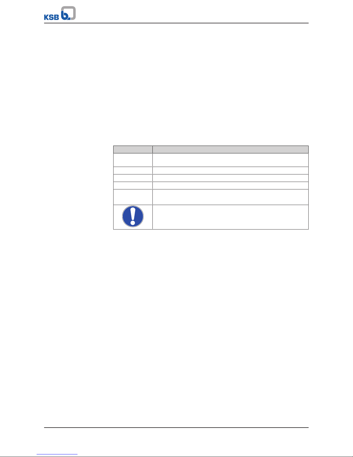
Table1: Symbols used in this manual
Symbol Description
✓ Conditions which need to be fulfilled before proceeding with the
step-by-step instructions
⊳ Safety instructions
⇨ Result of an action
⇨ Cross-references
1.
2.
Step-by-step instructions
Note
Recommendations and important information on how to handle
the product
Page 7
2 Safety
7 of 32
Ama-DrainerN 301/302/303/358
2 Safety
!
DANGER
All the information contained in this section refers to hazardous situations.
2.1 Key to safety symbols/markings
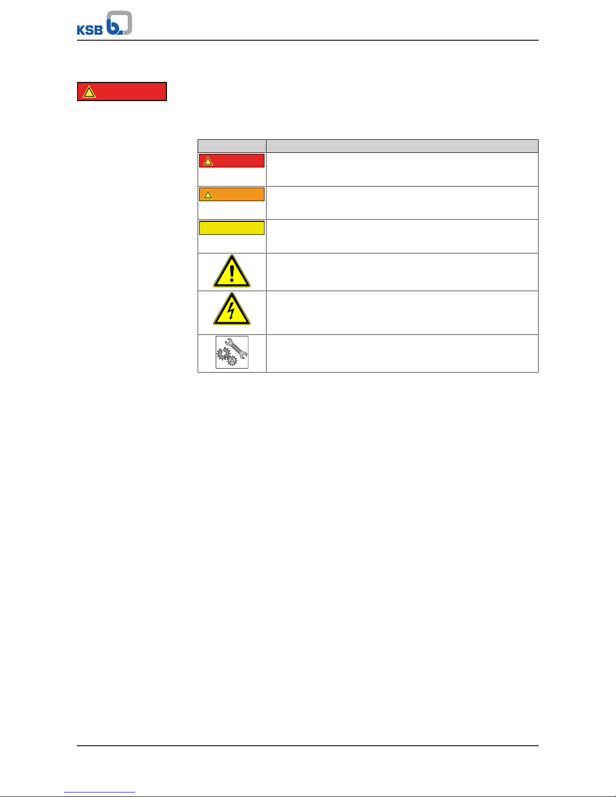
Table2: Definition of safety symbols/markings
Symbol Description
!
DANGER
DANGER
This signal word indicates a high-risk hazard which, if not avoided,
will result in death or serious injury.
!
WARNING
WARNING
This signal word indicates a medium-risk hazard which, if not
avoided, could result in death or serious injury.
CAUTION
CAUTION
This signal word indicates a hazard which, if not avoided, could
result in damage to the machine and its functions.
General hazard
In conjunction with one of the signal words this symbol indicates a
hazard which will or could result in death or serious injury.
Electrical hazard
In conjunction with one of the signal words this symbol indicates a
hazard involving electrical voltage and identifies information about
protection against electrical voltage.
Machine damage
In conjunction with the signal word CAUTION this symbol indicates
a hazard for the machine and its functions.
2.2 General
This manual contains general installation, operating and maintenance instructions
that must be observed to ensure safe pump operation and prevent personal injury
and damage to property.
The safety information in all sections of this manual must be complied with.
This manual must be read and completely understood by the specialist personnel/
operators responsible prior to installation and commissioning.
The contents of this manual must be available to the specialist personnel at the site
at all times.
Information attached directly to the pump must always be complied with and be
kept in a perfectly legible condition at all times. This applies to, for example:
▪ Arrow indicating the direction of rotation
▪ Markings for connections
▪ Name plate
The operator is responsible for ensuring compliance with all local regulations not
taken into account in this manual.
Page 8

2 Safety
8 of 32
Ama-DrainerN 301/302/303/358
2.3 Intended use
▪ The pump (set) must only be operated within the operating limits described in
the other applicable documents.
▪ Only operate pumps/pump sets which are in perfect technical condition.
▪ Do not operate the pump (set) in partially assembled condition.
▪ Only use the pump to handle the fluids described in the data sheet or product
literature of the pump model or variant.
▪ Never operate the pump without the fluid to be handled.
▪ Observe the minimum flow rates indicated in the data sheet or product literature
(to prevent overheating, bearing damage, etc).
▪ Observe the maximum flow rates indicated in the data sheet or product
literature (to prevent overheating, mechanical seal damage, cavitation damage,
bearing damage, etc).
▪ Do not throttle the flow rate on the suction side of the pump (to prevent
cavitation damage).
▪ Consult the manufacturer about any use or mode of operation not described in
the data sheet or product literature.
Prevention of foreseeable misuse
▪ Never open the discharge-side shut-off elements further than permitted.
– The maximum flow rates specified in the product literature or data sheet
would be exceeded.
– Risk of cavitation damage
▪ Never exceed the permissible operating limits specified in the data sheet or
product literature regarding pressure, temperature, etc.
▪ Observe all safety information and instructions in this manual.
2.4 Personnel qualification and training
All personnel involved must be fully qualified to transport, install, operate, maintain
and inspect the machinery this manual refers to.
The responsibilities, competence and supervision of all personnel involved in
transport, installation, operation, maintenance and inspection must be clearly
defined by the operator.
Deficits in knowledge must be rectified by means of training and instruction
provided by sufficiently trained specialist personnel. If required, the operator can
commission the manufacturer/supplier to train the personnel.
Training on the pump (set) must always be supervised by technical specialist
personnel.
2.5 Consequences and risks caused by non-compliance with this manual
▪ Non-compliance with this operating manual will lead to forfeiture of warranty
cover and of any and all rights to claims for damages.
▪ Non-compliance can, for example, have the following consequences:
– Hazards to persons due to electrical, thermal, mechanical and chemical
effects and explosions
– Failure of important product functions
– Failure of prescribed maintenance and servicing practices
– Hazard to the environment due to leakage of hazardous substances
Page 9

2 Safety
9 of 32
Ama-DrainerN 301/302/303/358
2.6 Safety awareness
In addition to the safety information contained in this manual and the intended use,
the following safety regulations shall be complied with:
▪ Accident prevention, health and safety regulations
▪ Explosion protection regulations
▪ Safety regulations for handling hazardous substances
▪ Applicable standards, directives and laws
2.7 Safety information for the operator/user
▪ The operator shall fit contact guards for hot, cold and moving parts and check
that the guards function properly.
▪ Do not remove any contact guards during operation.
▪ Provide the personnel with protective equipment and make sure it is used.
▪ Contain leakages (e.g. at the shaft seal) of hazardous fluids handled (e.g.
explosive, toxic, hot) so as to avoid any danger to persons and the environment.
Adhere to all relevant laws.
▪ Eliminate all electrical hazards. (In this respect refer to the applicable national
safety regulations and/or regulations issued by the local energy supply
companies.)
▪ If shutting down the pump does not increase potential risk, fit an emergency-
stop control device in the immediate vicinity of the pump (set) during pump set
installation.
▪ Make sure the system cannot be accessed by unauthorised persons (e.g. children).
2.8 Safety information for maintenance, inspection and installation
▪ Modifications or alterations of the pump are only permitted with the
manufacturer's prior consent.
▪ Use only original spare parts or parts authorised by the manufacturer. The use of
other parts can invalidate any liability of the manufacturer for resulting damage.
▪ The operator ensures that maintenance, inspection and installation is performed
by authorised, qualified specialist personnel who are thoroughly familiar with
the manual.
▪ Only carry out work on the pump (set) during standstill of the pump.
▪ Any work on the pump set shall only be performed when it has been
disconnected from the power supply (de-energised).
▪ The pump casing must have cooled down to ambient temperature.
▪ Pump pressure must have been released and the pump must have been drained.
▪ When taking the pump set out of service always adhere to the procedure
described in the manual. (ðSection6.3,Page18)
▪ Decontaminate pumps which handle fluids posing a health hazard.
▪ As soon as the work has been completed, re-install and/or re-activate any safety-
relevant and protective devices. Before returning the product to service, observe
all instructions on commissioning.
2.9 Unauthorised modes of operation
Never operate the pump (set) outside the limits stated in the data sheet and in this
manual.
The warranty relating to the operating reliability and safety of the supplied pump
(set) is only valid if the equipment is used in accordance with its intended use.
(ðSection2.3,Page8)
Page 10

3 Transport/Temporary Storage/Disposal
10 of 32
Ama-DrainerN 301/302/303/358
3 Transport/Temporary Storage/Disposal
3.1 Checking the condition upon delivery
1. On transfer of goods, check each packaging unit for damage.
2. In the event of in-transit damage, assess the exact damage, document it and
notify KSB or the supplying dealer (as applicable) and the insurer about the
damage in writing immediately.
3.2 Transport
CAUTION
Improper pump transport
Damage to the pump!
▷ To transport the pump/pump set always use the handle provided.
▷ Never suspend the pump (set) from the float switch (type SE only) or the power
supply cable for transport.
▷ Prevent the pump (set) from getting knocked or dropped.
3.3 Storage/preservation
CAUTION
Damage during storage by frost, humidity, dirt, UV radiation or vermin
Corrosion/contamination of the pump!
▷ Store the pump (set) in a dry, dark, frost-proof room not exposed to sunlight
where the atmospheric humidity is as constant as possible.
Store the pump (set) vertically in a dry, dark, frost-proof room not exposed to
sunlight. Under these conditions it does not need additional preservation.
3.4 Disposal
WARNING
Fluids, consumables and supplies which are hot and/or pose a health hazard
Hazard to persons and the environment!
▷ Collect and properly dispose of flushing fluid and any residues of the fluid
handled.
▷ Wear safety clothing and a protective mask if required.
▷ Observe all legal regulations on the disposal of fluids posing a health hazard.
1. Dismantle the pump (set).
Collect greases and other lubricants during dismantling.
2. Separate and sort the pump materials, e.g. by:
- Metals
- Plastics
- Electronic waste
- Greases and other lubricants
3. Dispose of materials in accordance with local regulations or in another
controlled manner.
Page 11

4 Description
11 of 32
Ama-DrainerN 301/302/303/358
4 Description
4.1 General description
▪ Submersible waste water pump (see submersible motor pump)
Pump for handling seepage water, chemically neutral, slightly contaminated waste
water, seawater1) and wash water.
4.2 Designation
Example: Ama-Drainer N 302 SE / NE / C
Table3: Designation key
Code Description
Ama-Drainer N 302 Type series
S With float switch
N Without float switch
E Motor version, e.g. E = single-phase AC motor
C Variant for aggressive water
4.3 Name plate
Ama®-Drainer N 301 SE
Hmax = 6.7 m
Classe F IP 68 T50 °C
2011
S-1101
39300070
MADE IN FRANCE
230 V~. 50 Hz 1.9 A 430 W
Qmax = 10 m3/h
2 m
KSB SAS
F-59 320 Sequedin
1
2
4
3
5
9
8
10
6
7
Fig.1: Name plate (example)
1 Type series, size 2 Rated voltage/frequency
3 Maximum head 4 Thermal class of winding insulation
5 Enclosure 6 Maximum fluid and ambient
temperature
7 Maximum immersion depth 8 Max. flow rate
9 Rated power 10 Series code
Key to the series code
S = series, 11 = year of construction 2011, 01 = week 1
4.4 Design details
Design
▪ Vertical installation
▪ Single-stage
▪ To EN 12050-2
▪ All wetted parts made of materials with anti-corrosive coating
1) Variant C only
Page 12

4 Description
12 of 32
Ama-DrainerN 301/302/303/358
Drive
▪ Single-phase AC motor
▪ Cooled by the fluid handled
▪ Thermal motor protection with automatic reset and start-up
▪ Earthed power supply cable
Pump casing
▪ Circular casing
Impeller type
▪ With free-flow impeller
Bearings
▪ Enclosed bearings, grease-packed for life
4.5 Configuration and function
1
3
4
5
2
6
7
8
1
3
4
5
2
6
7
8
Fig.2: Sectional drawing
1 Discharge nozzle
Optional: with hose connection
2 Bearing bracket
3 Rolling element bearing 4 Shaft
5 Rolling element bearing 6 Shaft seal
7 Impeller 8 Foot opening
Design
The pump is designed with an axial fluid inlet and an outlet parallel to the axis,
pointing upwards. (The outlet of Ama®-Drainer N 358 pumps is horizontal,
perpendicular to the axis.) The hydraulic system runs in common bearings and is
connected to the motor by a shaft coupling.
Function
The fluid enters the pump via an opening in the foot (8) and is accelerated outward
by the rotating impeller (7). In the flow passage of the pump casing the kinetic
energy of the fluid is converted into pressure energy. The fluid is pumped to the
discharge nozzle (1), where it leaves the pump. At the rear side of the impeller, the
shaft (4) enters the casing via the casing wall. The shaft passage through the cover is
sealed to the atmosphere with a shaft seal (6). The shaft runs in rolling element
bearings (3 and 5), which are supported by a bearing bracket (2). The bearing bracket
is linked with the pump casing and/or casing cover.
Sealing
The pump is sealed by three bi-directional shaft seals in tandem arrangement.
A lubricant reservoir between the seals ensures cooling and lubrication of the shaft
seals.
Page 13

4 Description
13 of 32
Ama-DrainerN 301/302/303/358
4.6 Scope of supply
Depending on the model, the following items are included in the scope of supply:
▪ Pump set
▪ Lift check valve
▪ Connection socket with internal thread
▪ Float switch/locking disc (for external control systems or dual-pump stations)
▪ Power cable with shockproof plug
Accessories
Further required accessories can be purchased from our distributors.
Page 14

5 Installation at Site
14 of 32
Ama-DrainerN 301/302/303/358
5 Installation at Site
5.1 Safety regulations
DANGER
Unsuitable electrical installation
Danger to life!
▷ Make sure the electrical installation meets the VDE 0100 installation rules (i.e.
sockets with earthing terminals).
▷ Make sure the electric mains is equipped with a residual current device of
maximum 30 mA.
▷ Always have the electrical connections installed by a trained and qualified
electrician.
▷ Only use the plugs and power cables supplied with the pump.
DANGER
Use in an outdoor area
Danger of death from electric shock!
▷ Any extension cords must match the quality of the supplied pump cable (10-
metre cable length).
▷ Do not expose electrical connections to any moisture.
DANGER
Continuous pump operation in swimming pools, garden ponds or similar
Danger of death from electric shock!
▷ Make sure that nobody is in the water while the pump is in operation.
▷ Only use the pump for draining swimming pools, garden ponds, etc. (It is
impermissible to use this pump as a recirculation pump, for example.)
5.2 Checks to be carried out prior to installation
Before installing the pump make sure that the following requirements are met:
▪ Check the data on the name plate of the pump to make sure it can be operated
on the available mains.
▪ The fluid to be handled matches the description of suitable fluids.
▪ The above safety instructions have been complied with.
Page 15

5 Installation at Site
15 of 32
Ama-DrainerN 301/302/303/358
5.3 Fitting the swing check valve and socket (if supplied but not fitted)
Ama-Drainer N 301/302/303 Ama-Drainer N 358
1
3
4
5
2
6
1
Fig.3: Fitting the swing check valve and socket
1 Discharge nozzle 2 Socket 1 1/4"
3 Swing check valve 4 Hose connection 1 1/2"
5 Suction valve 6 Screw plug
1. Position the swing check valve on the discharge nozzle.
For Ama-Drainer N 301/302/303: Make sure the disc of the swing check valve
opens upwards.
For Ama-Drainer N 358: Make sure the disc of the swing check valve opens
downwards.
2. Screw the socket on with the long thread and tighten it.
5.4 Adjusting the cut-in level control
Fig.4: Switching levels
b Cut-out level c Cut-in level
Table4: Cut-in levels and cut-out levels
Type series Factory setting Limits
2)
Cut-out level b
3)
[mm]
Cut-in level c
3)
[mm]
Cut-out level b
[mm]
Cut-in level c
3)
[mm]
Ama-Drainer N 301 SE 70 145 295 375
Ama-Drainer N 302 SE 110 200 315 420
Ama-Drainer N 303 SE 110 200 315 420
Ama-Drainer N 358 SE 110 230 395 540
For manual operation value b must not be lower than the following values:
▪ Ama-Drainer N 301/302/303: 15mm
▪ Ama-Drainer N 358: 37mm
2) Maximum values
3) Minimum values for automatic operation
Page 16

5 Installation at Site
16 of 32
Ama-DrainerN 301/302/303/358
Fig.5: Adjusting the cut-in level control
1. Unplug the pump from the electric mains.
2. Insert a screwdriver into the screw at the float and hold it in this position.
Do not turn the screw.
3. Push the float up or down to adjust it to the required cut-in level.
4. Pull the screwdriver back out again.
5. Check the cut-in level by moving the float up and down. You should be able to
hear a "click" each time the float is lifted up to the cut-in level.
6. Plug the pump back into the mains.
5.5 Piping
5.5.1 Connecting the piping (stationary installation – 5 metre cable length)
NOTE
The highest point of the discharge line must be above the flood level (usually street
level) to prevent any backflow from the sewage system.
Ama-Drainer N 301/302/303
1. Connect the pump and piping at the G 1¼ thread of the discharge nozzle. Use a
pipe with an inner diameter of 32 millimetres.
Ama-Drainer N 358
1. Connect the pump and piping at the G 1½ thread tangential discharge nozzle
of the suction cover. Use a pipe with an inner diameter of 40 millimetres.
5.5.2 Connecting the piping (transportable installation – 10 metre cable length)
Ama-Drainer N 301/302/303
1. A hose with an inner diameter of 30millimetres can be connected to the pump
set. To do so, screw a G 1¼ adaptor into the threaded socket (see accessories
"drainage hose set A 25 B").
2. Fasten the hose with a hose clip.
Page 17

5 Installation at Site
17 of 32
Ama-DrainerN 301/302/303/358
Ama-Drainer N 358
1. Screw on the G 1 ½" adaptor for a hose of 40 millimetres inner diameter (an
elbow is available as an option).
2. Fasten the hose with a hose clip.
5.6 Installing the pump set
c
b
E
h
Fig.6: Installation dimensions and switching levels
c Cut-in level b Cut-out level
Table5: Recommended installation dimensions
Size E
[mm]
h
[mm]
301 400×400 400
302/ 303 400×400 500
358 SE 400×450 550
1. If required, suspend the pump set using a rope attached to the handle.
2. Place the pump set on a solid surface.
Observe the recommended installation dimensions.
3. Position the pump set so that the float can move freely.
5.7 Connection to power supply
Plug the pump into the mains socket.
The pump switches on and off automatically.
Page 18

6 Commissioning/Start-up/Shutdown
18 of 32
Ama-DrainerN 301/302/303/358
6 Commissioning/Start-up/Shutdown
6.1 Start-up/shutdown
The pump's automatic control system will cut in when level "A" is reached and will
cut out when level "B" is reached. (ðSection5.6,Page17)
6.2 Operating limits
CAUTION
Unsuitable fluids
Damage to the pump!
▷ Never use the pump to handle corrosive, combustible or explosive fluids.
▷ Never use the pump to handle waste water containing faeces.
▷ Do not use the pump for foodstuff applications.
Table6: Overview
Characteristic Ama-Drainer N 301 Ama-Drainer N 302 Ama-Drainer N 303 Ama-Drainer N 358
Head 6.5m max. 10m max. 12.5m max. 8.5m max.
Flow rate 10m3/h max. 12m3/h max. 14m3/h max. 16.5m3/h max.
Immersion depth 2m max. 2m max. 2m max. 2m max.
Voltage/Frequency 230 V/50 Hz 230 V/50 Hz 230 V/50 Hz 230 V/50 Hz
Starting current 4.1A 9.5A 11.5A 9.5A
Maximum temperature,
continuous
0 to 50°C 0 to 50°C 0 to 50°C 0 to 50°C
Maximum temperature,
temporary
4)
+90°C +90°C +90°C -
Particle size
(Maximum diameter)
10mm 10mm 10mm 35mm
Residual water level
(Type NE for manual
operation)
15mm min. 15mm min. 15mm min. 37mm min.
Power input 430W max. 750W max. 1050W max. 850W max.
Enclosure IP68 IP68 IP68 IP68
Power cable H07RN8-F 3×1
2
H07RN8-F 3×1
2
H07RN8-F 3×1
2
H07RN8-F 3×1
2
TypeSEH05RN8-F 3×0.752H05RN8-F 3×0.752H05RN8-F 3×0.752-
Frequency of starts
[starts/hour]
30 max.
6.3 Shutdown/storage/preservation
6.3.1 Measures to be taken for shutdown
1. Unplug the system from the electric mains.
2. Wait for the pump to cool down (at least 10 minutes) before removing it from
the tank.
3. Separate the pump from the discharge line.
4. Unscrew the connection socket at the discharge nozzle and remove the swing
check valve.
4) Applies to standard design only
Page 19

6 Commissioning/Start-up/Shutdown
19 of 32
Ama-DrainerN 301/302/303/358
5. Clean the pump and its add-on parts under a water jet.
- Point the water jet into the discharge nozzle.
- For Ama-Drainer N 358: Unscrew the plug of the venting and cleaning system.
Remove the swing check valve and point the water jet into the opening.
6. Allow the parts to dry.
7. Re-install the connection socket and the swing check valve. Observe the
assembly sequence.
8. Store the pump vertically in a dry, dark and frost-proof room.
NOTE
Special preservation measures are not required.
6.4 Returning to service
(ðSection5,Page14)
Page 20

7 Servicing/Maintenance
20 of 32
Ama-DrainerN 301/302/303/358
7 Servicing/Maintenance
7.1 Safety regulations
DANGER
Power supply not disconnected
Danger to life!
▷ Pull the mains plug and secure the pump against unintentional start-up.
DANGER
Work on the pump set by unqualified personnel
Danger of death from electric shock!
▷ Have pump components modified and dismantled by authorised personnel
only.
WARNING
Insufficient stability
Risk of crushing hands and feet!
▷ During assembly/dismantling, secure the pump (set)/pump parts to prevent
tilting or tipping over.
WARNING
Fluids handled, consumables and supplies posing a health hazard
Hazard to persons and the environment!
▷ Clean the pump prior to any maintenance and installation work.
▷ Make sure persons cannot come into contact with the fluid handled.
7.2 Servicing/inspection
The pump is practically maintenance-free.
It will suffice to clean the pump once a year and carry out visual inspections of the
condition of the pump and supply line.
7.3 Drainage/disposal
WARNING
Fluids, consumables and supplies which are hot or pose a health hazard
Hazard to persons and the environment!
▷ Collect and properly dispose of flushing medium and any residues of the fluid
handled.
▷ Wear safety clothing and a protective mask, if required.
▷ Observe all legal regulations on the disposal of fluids posing a health hazard.
The pump will be automatically drained when it is taken out of the fluid handled.
Always flush and clean the pump before transporting it to the workshop. Provide a
certificate of decontamination for the pump set.
Page 21

7 Servicing/Maintenance
21 of 32
Ama-DrainerN 301/302/303/358
7.4 Dismantling/reassembling the pump set
7.4.1 General information/Safety regulations
Dismantling/reassembly work must be effected by authorised specialist personnel
only.
NOTE
All maintenance, service and installation work can be carried out by KSB Service or
authorised workshops. For contact details please refer to the enclosed "Addresses"
booklet or visit "www.ksb.com/contact" on the Internet.
7.4.2 Installing the pump in an Ama-Drainer-Box 021 waste water lifting unit /
Replacing Ama-Drainer 301 SE with Ama-Drainer N 301 SE
NOTE
The Ama-Drainer-Box 021/C for aggressive waste water cannot be fitted with an
Ama-DrainerN301SE/NE/C series pump. A special pump set from KSB's spare parts
programme is required as a replacement.
NOTE
Also observe the operating manual of Ama-Drainer-Box 021.
Table7: Limits of the float levels
Design Cut-out level b
[mm]
Cut-in level c
[mm]
Standard design ~50 ~190
Connection to a shower ~50 ~95
ü The waste water lifting unit has been disconnected from the mains.
ü The tank cover has been removed.
1. Remove the old pump (Ama-Drainer 301 SE) from the tank.
2. Remove handle 576 of the new pump (Ama-Drainer N 301 SE).
(Keep this handle as the name plate on it will be required as a reference in case
of any technical complaint.)
Fig.7: Removing the automatic switchgear
3. Pull automatic switchgear 79-1.1 out of its location in discharge casing 107 (see
Fig. "Removing the automatic switchgear").
Page 22

7 Servicing/Maintenance
22 of 32
Ama-DrainerN 301/302/303/358
1
Fig.8: Removing the metal strip
1 Metal strip
4. Remove the metal strip and press the automatic switchgear into its location (see
Fig. "Removing the metal strip").
5. Adjust the cut-in level control (ðSection5.4,Page15) . Observe the table
"Limits of the float levels".
CAUTION
Incorrect assembly
Float switch hits the bottom of the casing. Cut-out level of the pump cannot be
reached!
▷ For connection to a shower 2 spacer rings 411 (6/16 x 26, CR) have to be
inserted between the polysterene float and the rod.
1
2 3 4
Fig.9: Inserting the spacer rings at the float
1 Rod 2 Spacer ring
3 Polysterene float 4 Spacer ring
6. For connection to a shower insert 2 spacer rings 411 (6/16 x 26, CR) between the
polysterene float and the rod.
7. Insert the new pump into the tank and engage it in the anti-rotation device.
8. Connect the discharge line.
27 mm
Fig.10: Shortening the nozzle
9. Shorten the nozzle on the inner side of the tank cover to 27mm.
10. Check the cut-in/cut-out levels (ðSection5.4,Page15) and fit the cover.
11. Conduct a test-run for several start/stop cycles.
7.5 Recommended spare parts stock
It is not necessary to keep spare parts on stock.
Page 23

8 Trouble-shooting
23 of 32
Ama-DrainerN 301/302/303/358
8 Trouble-shooting
WARNING
Improper work to remedy faults
Risk of injury!
▷ For any work performed to remedy faults, observe the relevant information
given in this operating manual and/or in the product literature provided by the
accessories manufacturer.
If problems occur that are not described in the following table, consultation with the
KSB customer service is required.
Table8: Trouble-shooting
Trouble-shooting Possible cause Remedy
5)
Pump is running, but does not or
hardly deliver.
The hydraulic system is clogged by
foreign matter.
Clean the hydraulic system with a water
jet. (ðSection6.3,Page18)
The discharge line is closed. Open all accessories fitted at the
discharge line.
The lift check valve has been fitted for
the opposite direction of flow or is
clogged.
Reassemble observing the correct
sequence (ðSection9.1,Page24) or
clean the lift check valve.
The pump is not running or only
for a short time.
The thermal motor protection device
triggers because:
1) Pump overheating Check the fluid temperature.
2) Pump running dry Verify the minimum fluid level.
The power supply is interrupted Check the electrical installation.
5) Pump pressure must be released before attempting to remedy faults on parts which are subjected to pressure. Disconnect
the pump from the power supply and let it cool down.
Page 24

9 Related Documents
24 of 32
Ama-DrainerN 301/302/303/358
9 Related Documents
9.1 Exploded view and list of components
(824)
824
576
550
747
107
79-1.1
(576)
2x(900.1)
1x(900.1)
(800)
230
230
101
4x(900.2)
101
101
4x(900.2)
101
(800)
(133)
(837)
837
(837)
(410)
(800)
(800)
(133)
(837)
(410)
(79-1.2)
(79-1.2)
(79-1.2)
837
(837)
(79-1.2)
Ama-Drainer N 301/302/303
Ama-Drainer N 358
Fig.11: Ama-Drainer N – Exploded view
Page 25

9 Related Documents
25 of 32
Ama-DrainerN 301/302/303/358
Table9: List of components
Part No. Description
101 Pump casing
107 Discharge casing
230 Impeller
550 Locking disc for float
576 Handle
747 Swing check valve and inspection hole
79-1.1 Automatic switch (external)
800 Motor
824 Cable
Page 26

10 EU Declaration of Conformity
26 of 32
Ama-DrainerN 301/302/303/358
10 EU Declaration of Conformity
Manufacturer: KSB S.A.S.
128, rue Carnot,
59320 Sequedin (France)
The manufacturer herewith declares that the product:
Ama-Drainer N 301/302/303/358
Series code: 2016w16 - 2018w52
▪ is in conformity with the provisions of the following Directives as amended from time to time:
– Pump set: EC Machinery Directive 2006/42/EC
– Pump set: Electromagnetic Compatibility Directive 2014/30/EU
The manufacturer also declares that
▪ the following harmonised international standards have been applied:
– ISO 12100
– EN 809
– EN 60034-1, EN 60034-5/A1
– EN 60335-1/A1, EN 60335-2-41
Person authorised to compile the technical file:
Dr Frank Obermair
Technical Project Manager Product Development Pump Systems and Drives
KSB SE & Co. KGaA
Johann-Klein-Straße 9
67227 Frankenthal (Germany)
The EU Declaration of Conformity was issued in/on:
Frankenthal, 01 February 2018
Joachim Schullerer
Head of Product Development Pump Systems and Drives
KSB SE & Co. KGaA
Johann-Klein-Straße 9
67227 Frankenthal
Page 27

11 Certificate of Decontamination
27 of 32
Ama-DrainerN 301/302/303/358
11 Certificate of Decontamination
Type: ................................................................................................................................
Order number/
Order item number6): ................................................................................................................................
Delivery date: ................................................................................................................................
Field of application: ................................................................................................................................
Fluid handled6): ................................................................................................................................
Please tick where applicable6):
Radioactive Explosive Corrosive Toxic
Harmful Bio-hazardous Highly flammable Safe
Reason for return6): ................................................................................................................................
Comments: ................................................................................................................................
................................................................................................................................
The product/accessories have been carefully drained, cleaned and decontaminated inside and outside prior to dispatch/
placing at your disposal.
We herewith declare that this product is free from hazardous chemicals, biological and radioactive substances.
For mag-drive pumps, the inner rotor unit (impeller, casing cover, bearing ring carrier, plain bearing, inner rotor) has been
removed from the pump and cleaned. In cases of containment shroud leakage, the outer rotor, bearing bracket lantern,
leakage barrier and bearing bracket or intermediate piece have also been cleaned.
For canned motor pumps, the rotor and plain bearing have been removed from the pump for cleaning. In cases of leakage at
the stator can, the stator space has been examined for fluid leakage; if fluid handled has penetrated the stator space, it has
been removed.
No special safety precautions are required for further handling.
The following safety precautions are required for flushing fluids, fluid residues and disposal:
...............................................................................................................................................................
...............................................................................................................................................................
We confirm that the above data and information are correct and complete and that dispatch is effected in accordance with the
relevant legal provisions.
.................................................................... ....................................................... .......................................................
Place, date and signature Address Company stamp
6) Required fields
Page 28

Index
28 of 32
Ama-DrainerN 301/302/303/358
Index
A
Applications8
B
Bearings12
C
Certificate of decontamination27
Commissioning18
D
Design11
Designation11
Disposal10
Drive12
E
Exploded view24
I
Impeller type12
Intended use8
M
Misuse8
N
Name plate11
O
Order number6
P
Product description11
Pump casing12
S
Safety7
Safety awareness9
Scope of supply13
Shutdown18
Start-up18
T
Transport10
Trouble-shooting
Causes of faults and remedies23
Page 29

Page 30

Page 31

Page 32

KSB S.A.S.
128, rue Carnot • 59320 Sequedin (France)
B.P. 60095 • 59482 Haubourdin Cedex (France)
Tél. +33 3 2022-7000 • Fax +33 3 2022-7099
www.ksb.com
2337.81/09-EN (39300248)
 Loading...