

Page 1
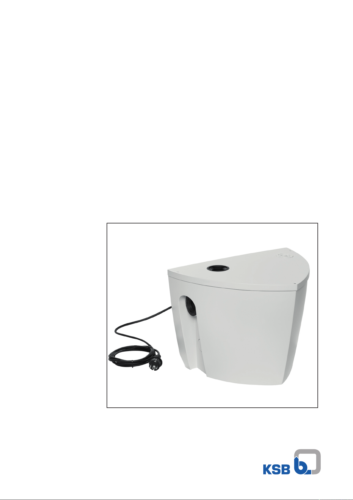
Automatic Waste Water Lifting Unit
Ama-Drainer-Box Mini
Installation/Operating Manual
Page 2

Legal information/Copyright
Installation/Operating Manual Ama-Drainer-Box Mini
Original operating manual
All rights reserved. The contents provided herein must neither be distributed, copied, reproduced,
edited or processed for any other purpose, nor otherwise transmitted, published or made available to a
third party without the manufacturer's express written consent.
Subject to technical modification without prior notice.
© KSB SE & Co. KGaA, Frankenthal 19/10/2018
Page 3

Contents
Contents
1 General.................................................................................................................................................... 6
1.1 Principles ...........................................................................................................................................................6
1.2 Installation of partly completed machinery....................................................................................................6
1.3 Target group.....................................................................................................................................................6
1.4 Other applicable documents............................................................................................................................6
1.5 Symbols .............................................................................................................................................................6
1.6 Key to safety symbols/markings.......................................................................................................................7
2 Safety...................................................................................................................................................... 8
2.1 General..............................................................................................................................................................8
2.2 Intended use .....................................................................................................................................................8
2.3 Personnel qualification and training...............................................................................................................9
2.4 Consequences and risks caused by non-compliance with this manual .........................................................9
2.5 Safety awareness ..............................................................................................................................................9
2.6 Safety instructions for the operator/user........................................................................................................9
2.7 Safety information for maintenance, inspection and installation ..............................................................10
2.8 Unauthorised modes of operation................................................................................................................10
3 Transport/Temporary Storage/Disposal............................................................................................. 11
3.1 Checking the condition upon delivery..........................................................................................................11
3.2 Transport.........................................................................................................................................................11
3.3 Storage/preservation......................................................................................................................................11
3.4 Return to supplier...........................................................................................................................................11
3.5 Disposal ...........................................................................................................................................................12
4 Description............................................................................................................................................ 13
4.1 General description ........................................................................................................................................13
4.2 Designation.....................................................................................................................................................13
4.3 Name plate......................................................................................................................................................13
4.4 Design details..................................................................................................................................................14
4.5 Configuration and function...........................................................................................................................14
4.6 Noise characteristics .......................................................................................................................................15
4.7 Dimensions and weights ................................................................................................................................15
4.8 Scope of supply...............................................................................................................................................15
4.9 Accessories ......................................................................................................................................................15
5 Installation at Site................................................................................................................................ 16
5.1 Safety regulations...........................................................................................................................................16
5.2 Checks to be carried out prior to installation...............................................................................................17
5.3 Installing the lifting unit................................................................................................................................18
5.4 Connecting the piping ...................................................................................................................................19
5.5 Installing the pump set ..................................................................................................................................21
5.6 Electrical connection ......................................................................................................................................25
6 Commissioning/Start-up/Shutdown................................................................................................... 27
6.1 Commissioning/Start-up.................................................................................................................................27
6.2 Operating limits..............................................................................................................................................28
6.3 Shutdown/storage/preservation ....................................................................................................................29
6.4 Returning to service .......................................................................................................................................30
7 Servicing/Maintenance........................................................................................................................ 31
7.1 Safety regulations...........................................................................................................................................31
7.2 Maintenance/inspection.................................................................................................................................31
7.3 Drainage/cleaning ..........................................................................................................................................32
7.4 Replacing the pump set .................................................................................................................................32
7.5 Recommended spare parts stock...................................................................................................................34
Ama-Drainer-Box Mini
3 of 44
Page 4

Contents
8 Trouble-shooting.................................................................................................................................. 35
9 Related Documents.............................................................................................................................. 36
9.1 Exploded view and list of components .........................................................................................................36
9.2 Connections ....................................................................................................................................................37
9.3 Dimensions......................................................................................................................................................38
9.4 Installation example.......................................................................................................................................39
10 EU Declaration of Conformity............................................................................................................. 40
11 Declaration of Performance as per Regulation (EU) No. 305/2011, Annex III.................................. 41
12 Certificate of Decontamination........................................................................................................... 42
Index ..................................................................................................................................................... 43
4 of 44
Ama-Drainer-Box Mini
Page 5

Glossary
Glossary
Backflow
Waste water flowing back from the sewer into the
connected drainage piping
Backflow loop
The section of the discharge pipe of a waste water
lifting unit that is located above the flood level
Certificate of decontamination
A certificate of decontamination is enclosed by the
customer when returning the product to the
manufacturer to certify that the product has been
properly drained to eliminate any environmental
and health hazards arising from components in
contact with the fluid handled.
Collecting tank
Component of a waste water lifting unit in which
the incoming waste water is stored in
unpressurised condition prior to automatic lifting.
EN 12050-2
European Standard for waste water lifting units
which are used to dispose of faeces-free waste
water occurring below the flood level of buildings
and sites. It defines general requirements as well
as principles of construction and testing.
Waste water
Water which has been changed by some type of
use, e.g. domestic waste water
Waste water lifting unit
Device for collecting and automatically lifting
faecal-free waste water above the flood level
EN 12056-4
European Standard governing the selection,
operation and maintenance of waste water lifting
units within buildings and sites.
Flood level
Maximum backflow level of waste water in a
drainage system
Inlet line
Pipe used for draining waste water from sanitary
installations into the lifting unit
Submersible motor pump
Submersible motor pumps are floodable, closecoupled units which are not self-priming. The
pumps are usually operated completely
submerged. They may be operated outside the
fluid for short periods of time, until the minimum
fluid level has been reached.
Swing check valve
Element of a waste water lifting unit which
prevents waste water from flowing back from the
discharge line into the waste water lifting unit.
Ama-Drainer-Box Mini
5 of 44
Page 6
1 General
1 General
1.1 Principles
This operating manual is valid for the type series and variants indicated on the front
cover.
The manual describes the proper and safe use of this equipment in all phases of
operation.
The name plate indicates the type series/size and main operating data. The works
number/serial number uniquely describes the system and is used as identification in
all further business processes.
In the event of damage, immediately contact your nearest KSB Service centre to
maintain the right to claim under warranty.
1.2 Installation of partly completed machinery
To install partly completed machinery supplied by KSB refer to the sub-sections under
Servicing/Maintenance.
1.3 Target group
This operating manual is aimed at the target group of trained and qualified specialist
technical personnel. (ðSection2.3,Page9)
1.4 Other applicable documents
Table1: Overview of other applicable documents
Document Contents
Sub-supplier product literature Operating manuals and other product literature
of accessories and integrated machinery
components, operating manual of submersible
motor pump
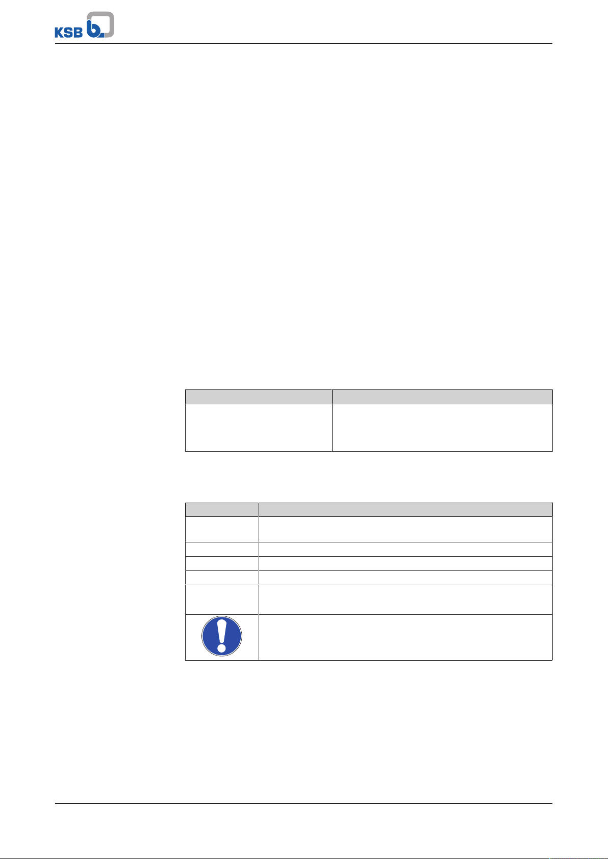
1.5 Symbols
Table2: Symbols used in this manual
Symbol Description
✓ Conditions which need to be fulfilled before proceeding with the
step-by-step instructions
⊳ Safety instructions
⇨
⇨ Cross-references
1.
2.
Result of an action
Step-by-step instructions
Note
Recommendations and important information on how to handle
the product
6 of 44
Ama-Drainer-Box Mini
Page 7
1 General
!
DANGER
!
WARNING
CAUTION
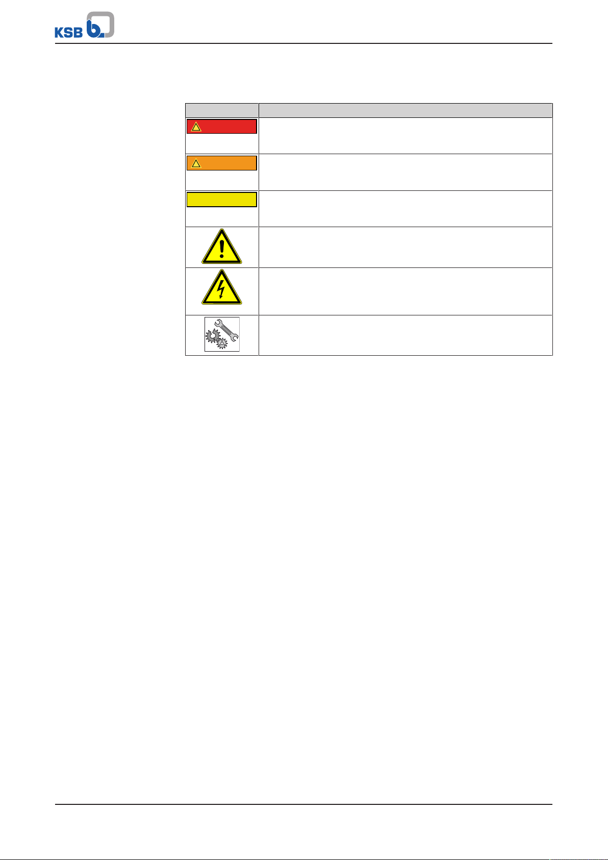
1.6 Key to safety symbols/markings
Table3: Definition of safety symbols/markings
Symbol Description
DANGER
This signal word indicates a high-risk hazard which, if not avoided,
will result in death or serious injury.
WARNING
This signal word indicates a medium-risk hazard which, if not
avoided, could result in death or serious injury.
CAUTION
This signal word indicates a hazard which, if not avoided, could
result in damage to the machine and its functions.
General hazard
In conjunction with one of the signal words this symbol indicates a
hazard which will or could result in death or serious injury.
Electrical hazard
In conjunction with one of the signal words this symbol indicates a
hazard involving electrical voltage and identifies information about
protection against electrical voltage.
Machine damage
In conjunction with the signal word CAUTION this symbol indicates
a hazard for the machine and its functions.
Ama-Drainer-Box Mini
7 of 44
Page 8

2 Safety
!
DANGER
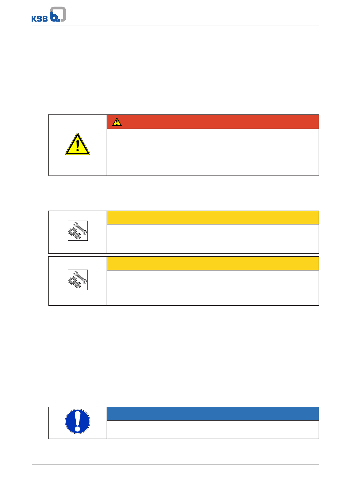
2 Safety
All the information contained in this section refers to hazardous situations.
In addition to the present general safety information the action-related safety
information given in the other sections must be observed.
2.1 General
This operating manual contains general installation, operating and maintenance
instructions that must be observed to ensure safe operation of the system and
prevent personal injury and damage to property.
The safety information in all sections of this manual must be complied with.
The operating manual must be read and understood by the responsible specialist
personnel/operators prior to installation and commissioning.
The contents of this operating manual must be available to the specialist personnel
at the site at all times.
Information attached directly to the product must always be complied with and kept
in a perfectly legible condition at all times. This applies to, for example:
▪ Arrow indicating the direction of rotation
▪ Markings for connections
▪ Name plate
The operator is responsible for ensuring compliance with all local regulations not
taken into account in this operating manual.
2.2 Intended use
▪ The lifting unit must only be operated within the operating limits described in
the other applicable documents.
▪ Only operate lifting units which are in perfect technical condition.
▪ Do not operate partially assembled lifting units.
▪ Only use the lifting unit to handle the fluids described in the product literature
of the respective design variant.
▪ Never operate the lifting unit without the fluid to be handled
▪ Observe the minimum flow rates indicated in the data sheet or product literature
(to prevent overheating, bearing damage, etc).
▪ Observe the minimum flow rate and maximum flow rate indicated in the data
sheet or product literature (to prevent overheating, mechanical seal damage,
cavitation damage, bearing damage, etc).
▪ Do not throttle the flow rate on the inlet side of the lifting unit (to prevent
cavitation damage)
▪ Consult the manufacturer about any use or mode of operation not described in
the data sheet or product literature.
Prevention of foreseeable misuse
▪ Never exceed the permissible application and operating limits specified in the
data sheet or product literature regarding temperature, etc.
▪ Observe all safety information and instructions in this manual.
8 of 44
Ama-Drainer-Box Mini
Page 9

2 Safety
2.3 Personnel qualification and training
All personnel involved must be fully qualified to transport, install, operate, maintain
and inspect the equipment this manual refers to.
The responsibilities, competence and supervision of all personnel involved in
transport, installation, operation, maintenance and inspection must be clearly
defined by the operator.
Deficits in knowledge must be rectified by means of training and instruction
provided by sufficiently trained specialist personnel. If required, the operator can
commission the manufacturer/supplier to train the personnel.
Training on the pump (set) must always be supervised by technical specialist
personnel.
This device may be operated by children from the age of 8 as well as by persons of
limited physical, sensory or mental abilities or lacking experience and knowledge,
provided that they are supervised, they have been instructed on how to use this
device safely and they understand the hazards it presents. It is impermissible for
children to play with this device. Children must not clean the device or perform any
service work to be carried out by the operator at the device without supervision.
2.4 Consequences and risks caused by non-compliance with this manual
▪ Non-compliance with these operating instructions will lead to forfeiture of
warranty cover and of any and all rights to claims for damages.
▪ Non-compliance can, for example, have the following consequences:
– Hazards to persons due to electrical, thermal, mechanical and chemical
effects and explosions
– Failure of important product functions
– Failure of prescribed maintenance and servicing practices
– Hazard to the environment due to leakage of hazardous substances
2.5 Safety awareness
In addition to the safety information contained in this manual and the intended use,
the following safety regulations shall be complied with:
▪ Accident prevention, health regulations and safety regulations
▪ Explosion protection regulations
▪ Safety regulations for handling hazardous substances
▪ Applicable standards, directives and laws
2.6 Safety instructions for the operator/user
▪ Fit protective equipment (e.g. contact guards) supplied by the operator for hot,
cold or moving parts, and check that the equipment functions properly.
▪ Do not remove any protective equipment (e.g. contact guards) during operation.
▪ Provide the personnel with protective equipment and make sure it is used.
▪ Contain leakages (e.g. at the shaft seal) of hazardous fluids handled (e.g.
explosive, toxic, hot) so as to avoid any danger to persons and the environment.
Adhere to all relevant laws.
▪ Eliminate all electrical hazards. (In this respect refer to the applicable national
safety regulations and/or regulations issued by the local energy supply
companies.)
Ama-Drainer-Box Mini
9 of 44
Page 10

2 Safety
2.7 Safety information for maintenance, inspection and installation
▪ Modifications or alterations of the lifting unit require the manufacturer's prior
consent.
▪ Use only original spare parts or parts authorised by the manufacturer. The use of
other parts can invalidate any liability of the manufacturer for resulting damage.
▪ The operator ensures that maintenance, inspection and installation are
performed by authorised, qualified specialist personnel who are thoroughly
familiar with the manual.
▪ Carry out work on the lifting unit during standstill only.
▪ The pump casing must have cooled down to ambient temperature.
▪ Pump pressure must have been released and the pump must have been drained.
▪ When taking the lifting unit out of service always adhere to the procedure
described in the manual.
▪ Decontaminate lifting units which handle fluids posing a health hazard.
▪ As soon as the work has been completed, re-install and re-activate any safety-
relevant devices and protective devices. Before returning the product to service,
observe all instructions on commissioning.
▪ Make sure the lifting unit cannot be accessed by unauthorised persons (e.g.
children).
2.8 Unauthorised modes of operation
Always observe the limits stated in the product literature.
The warranty relating to the operating reliability and safety of the lifting unit
supplied is only valid if the equipment is used in accordance with its intended use.
10 of 44
Ama-Drainer-Box Mini
Page 11
3 Transport/Temporary Storage/Disposal
3 Transport/Temporary Storage/Disposal
3.1 Checking the condition upon delivery
1. On transfer of goods, check each packaging unit for damage.
2. In the event of in-transit damage, assess the exact damage, document it and
notify KSB or the supplying dealer and the insurer about the damage in writing
immediately.
3.2 Transport
DANGER
Lifting unit falling off the pallet
Risk of injury from falling lifting unit!
▷ Always transport the lifting unit in a horizontal position.
▷ Never suspend the lifting unit by its power cable.
▷ Always prevent the lifting unit from getting knocked or dropped.
3.3 Storage/preservation
If commissioning is to take place some time after delivery, we recommend that the
following measures be taken for storage.
CAUTION
Damage during storage due to frost, humidity, dirt, UV radiation or vermin
Corrosion/contamination of the lifting unit!
▷ Store the lifting unit in a frost-proof, roofed area.
CAUTION
Wet, contaminated or damaged openings and connections
Leakage of or damage to the lifting unit!
▷ Only remove caps/covers from the openings of the lifting unit at the time of
installation.
Store the lifting unit in a dry, protected room where the atmospheric humidity is as
constant as possible.
3.4 Return to supplier
1. Prior to returning the product to the supplier, flush and clean it, particularly if it
has been used in noxious, explosive, hot or other hazardous fluids.
2. If the product has been used in fluids whose residues could lead to corrosion
damage in the presence of atmospheric humidity or could ignite upon contact
with oxygen, the product must also be neutralised and treated with anhydrous
inert gas to ensure drying.
3. Always complete and enclose a certificate of decontamination when returning
the product. (ðSection12,Page42)
Indicate any safety measures and decontamination measures taken.
NOTE
If required, a blank certificate of decontamination can be downloaded from the
following web site: www.ksb.com/certificate_of_decontamination
Ama-Drainer-Box Mini
11 of 44
Page 12
3 Transport/Temporary Storage/Disposal
3.5 Disposal
WARNING
Fluids handled, consumables and supplies which are hot and/or pose a health
hazard
Hazard to persons and the environment!
▷ Collect and properly dispose of flushing fluid and any fluid residues.
▷ Wear safety clothing and a protective mask if required.
▷ Observe all legal regulations on the disposal of fluids posing a health hazard.
1. Dismantle the lifting unit.
Collect greases and other lubricants during dismantling.
2. Separate and sort the pump materials, e.g. by:
- Metals
- Plastics
- Electronic waste
- Greases and other lubricants
3. Dispose of materials in accordance with local regulations or in another
controlled manner.
12 of 44
Ama-Drainer-Box Mini
Page 13

4 Description
Ama-Drainer-Box Mini C
230 V ~
EN 12 050-2
10 m³7h
50 Hz
6,7 m
9 kg
430 W
0197 13
FO002059 Made in Germany
DoP2336.2-01
t max. 50 °C
2016w13
Johann-Klein-Straße 9
Deutschland
67227 Frankenthal
KSB SE & Co. KGaA
1
2
3
4
5
6
7
8
9
10
11
12
4 Description
4.1 General description
▪ Automatic waste water lifting unit
Standard design
▪ Chemically neutral waste water
▪ Slightly contaminated waste water (up to 50°C max.)
▪ Wash water (up to 90 °C max. for short periods t ≤ 3minutes)
Variant C for aggressive fluids.
In addition to standard design:
▪ Swimming pool water
▪ Brackish water
▪ Seawater
▪ Water containing salt
▪ Aggressive fluids
▪ Condensate from heat recovery applications
4.2 Designation
Example: Ama-Drainer-Box Mini C
Table4: Designation key
Code Description
Ama-Drainer-Box Type series
Mini Small waste water lifting unit
C C variant for aggressive fluids
4.3 Name plate
Fig.1: Name plate (example)
1 Type series, size 2 Rated frequency
3 Rated voltage 4 Maximum head
5 Max. permissible flow rate 6 Principles of construction and testing
7 Total weight 8 Notifying body / year of introduction
9 Reference number of the declaration
of performance
11 Fluid temperature 12 Year of production
Ama-Drainer-Box Mini
The name plate is attached inside the tank.
10 Rated power
13 of 44
Page 14

4 Description
2
1
3
4
5
4.4 Design details
Design
▪ Tank made of impact-resistant plastic
▪ Odour-proof cover with activated carbon filter and integrated overflow
protection
▪ Submersible motor pump which starts and stops automatically, with float switch
▪ Integrated swing check valve
▪ To EN 12050-2
Installation
▪ Stationary above-floor installation
▪ Stationary wall mounting
Drive
▪ AC motor
▪ Integrated temperature switch
▪ Cable and shockproof plug
Impeller type
▪ Open multi-vane impeller
▪ Free passage= 10 mm
Connections
▪ Inlet DN32 /DN40 /DN50
▪ Discharge-side connection DN40
▪ Shower connection DN 50
▪ Venting via DN 40 spigot and socket connection
4.5 Configuration and function
Fig.2: Description and sectional drawing of the waste water lifting unit
1 Discharge-side connection 4 Float switch
2 Tank 5 Submersible motor pump
Design The waste water lifting unit consists of a stable tank (2) with integrated submersible
Function The fluid to be handled flows into the waste water lifting unit through an inlet (3)
3 Inlet
motor pump (5), an inlet-side connection (3) and a discharge-side connection (1).
and is collected in an odour-tight and water-tight plastic tank (2). When a specified
fluid level is reached, the float switch (4) triggers the automatic start of the
14 of 44
Ama-Drainer-Box Mini
Page 15

4 Description
submersible motor pump (5). The fluid handled is pumped through the dischargeside connection (1) to a level above the flood level and discharged into the public
sewer.
4.6 Noise characteristics
Sound pressure level < 70 dB(A)
4.7 Dimensions and weights
For dimensions refer to the outline drawing of the lifting unit.
(ðSection9.3,Page38)
The total weight of the lifting unit equals 9kg max.
4.8 Scope of supply
Depending on the design variant the following components are included in the scope
of supply1):
▪ Tank made of impact-resistant plastic
▪ Submersible motor pump which starts and stops automatically, with float switch
▪ Odour-proof cover with activated carbon filter and integrated overflow
protection
▪ Inlet DN32 /DN40 /DN50
▪ Discharge-side connection DN40
▪ Shower connection DN 50
4.9 Accessories
▪ M1 alarm contactor
▪ KSB washing machine interrupter
Further required accessories can be purchased from our distributors.
2)
3)
1) Supplied fully assembled ex works
2) In combination with one of KSB's alarm switchgears AS 0, AS 2, AS 4 or AS 5 the M1 alarm contactor triggers an alarm if the
permissible fluid level in the collecting tank is exceeded.
3) The KSB washing machine interrupter triggers an alarm and stops the washing machine before the collecting tank
overflows.
Ama-Drainer-Box Mini
15 of 44
Page 16

5 Installation at Site
5 Installation at Site
5.1 Safety regulations
DANGER
Power supply not disconnected
Danger to life!
▷ Pull the mains plug and secure the pump against unintentional start-up.
DANGER
Electrical connection work by unqualified personnel
Danger of death from electric shock!
▷ Always have the electrical connections installed by a trained and qualified
electrician.
▷ Observe regulations IEC60364.
DANGER
Unsuitable electrical installation
Danger to life!
▷ Make sure the electrical installation meets the VDE 0100 installation rules (i.e.
sockets with earthing terminals).
▷ Make sure the electric mains is equipped with a residual current device of
maximum 30 mA.
▷ Always have the electrical connections installed by a trained and qualified
electrician.
DANGER
Improper use
Danger of death from electric shock!
▷ Any extension cords must match the quality of the power cable supplied with
the pump.
▷ Do not expose electrical connections or devices to moisture.
NOTE
If the supply of mains voltage is interrupted or the submersible motor pump is
defective, there is a risk of flooding damage. Prevent damage by using a mainsindependent alarm switchgear or a KSB washing machine interrupter.
16 of 44
Ama-Drainer-Box Mini
Page 17

5 Installation at Site
5.2 Checks to be carried out prior to installation
Before installing the lifting unit make sure that the following requirements are met:
▪ Check the data on the name plate of the lifting unit to make sure it can be
operated on the available mains.
▪ The fluid to be handled matches the description of suitable fluids.
▪ The above safety instructions have been complied with.
▪ The place of installation is frost-proof.
NOTE
Observe the provisions of EN 12056 "Gravity Drainage Systems in Buildings" when
installing the unit at site.
NOTE
Lifting units in an odour-proof enclosure should be vented via the roof.
NOTE
Other operating manuals that describe components of this lifting unit must also be
observed.
Any transport locks that might have been provided have to be removed prior to
assembly and installation.
NOTE
Lifting units should not be installed next to sleeping or living quarters.
Ama-Drainer-Box Mini
17 of 44
Page 18

5 Installation at Site
160
900
591
280
296
591
595.01
1
2
595.02
5.3 Installing the lifting unit
Fig.3: Installing the waste water lifting unit
160 Cover 591 Collecting tank
900 Screw (with captive fastener)
5.3.1 Mounting the system on a level floor
1. Undo 3 screws 900 with a suitable tool and take off cover 160.
2. Remove the parts located in tank 591 and keep them in a safe place.
3. Use adhesive tape to stick the 3 supplied rubber buffers 595.01 (Ø 10×4) into the
recesses provided at the bottom of tank 591.
4. Place tank 591 on a level floor and align with the help of a spirit level.
5.3.2 Mounting the system on the wall
Fig.4: Wall mounting, dimensions in [mm]
1. Undo 3 screws 900 with a suitable tool and take off cover 160.
2. Remove the parts located in tank 591 and keep them in a safe place.
3. Observe the information given on the drilling template4).
4. Use the drilling template and a spirit level to mark and drill the holes for
fastening the collecting tank.
Leave a clearance of approximately 80 to 90 mm between the waste water lifting
unit and the tank floor.
5. Insert two commercial plug fixings (2) and screw in J-bolts (1).
6. Use the self-adhesive foil to stick the rubber buffers 595.01/.02 included in the
scope of supply to the back of the tank 591 (see illustration below).
7. Attach tank 591 to the J-bolts.
4) Included in the scope of supply
18 of 44
Ama-Drainer-Box Mini
Page 19

5 Installation at Site
1
3
2
5.4 Connecting the piping
CAUTION
Stresses and strains at the piping
Impermissible load acting on the collecting tank!
▷ Connect the piping without transmitting any stresses or strains; make sure that
no forces and moments act on the collecting tank.
▷ Protect the piping against frost.
NOTE
All connections are suitable for standardised pipe dimensions. The connections are
pressure-sealed and flexible.
If the waste water lifting unit is located below the flood level, the discharge line
must be laid with a backflow loop (180° bend) above the flood level.
If flooding above the flood level could occur, we recommend installing a gate valve
in close proximity to the system.
5.4.1 Connecting the inlet and discharge line
Fig.5: Connecting the inlet and discharge line
1 + 2 Socket DN 50, horizontal
either for inlet line with fitting DN32 / DN40 / DN50 or
for discharge outlet with fitting DN40
3 Socket DN 50, vertical
either for inlet line with fitting DN32 / DN40 / DN50 or for connecting a
washing machine (via Y-drain)
Connecting the inlet line
ü The cover has been removed.
ü The collecting tank has been installed properly.
ü Piping weights have been supported at the site.
1. Select fitting 720.2/.3/.4 for the corresponding diameter of the pipe.
2. Press the fitting into the socket (1, 2 or 3) provided for the inlet. Use a lubricant.
3. Insert the inlet line into the collecting tank through the fitting. The pipe end
has to protrude into the collecting tank by approximately 30 mm.
Ama-Drainer-Box Mini
19 of 44
Page 20

5 Installation at Site
720.5
411
920
90
Connecting the discharge line
ü The cover has been removed.
ü The collecting tank has been installed properly.
ü Piping weights have been supported at the site.
1. Press fitting 720.3 into the socket (1 or 2) provided for the discharge line. Use a
lubricant.
2. Insert the discharge line into the collecting tank through the fitting. The pipe
end has to protrude into the collecting tank by approximately 35 mm.
3. Close the unrequired socket with fitting 720.2 and plug 916.2.
5.4.2 Connecting auxiliary connections
Connection to a shower
CAUTION
Backflow into the shower basin or bathtub
The water is not completely drained!
▷ Observe the minimum installation height for shower basins and bathtubs
(gradient of 1:50 from the shower basin to the inlet of the lifting unit).
(ðSection9.4,Page39)
Fig.6: Shower connection, dimensions [mm]
Fig.7: Opening the shower connection
1. Open the perforated part of the side wall of the collecting tank and debur the
hole using suitable tools.
2. Insert fitting 720.5 with joint ring 411 into the hole and fasten it from the inside
with nut 920.
20 of 44
Ama-Drainer-Box Mini
Page 21

5 Installation at Site
719
733
733
720.1
719
733
720.1
A B
Connecting the vent line
NOTE
Venting is effected directly into the room the waste water lifting unit is installed in
by means of the integrated activated charcoal filter.
If the waste water lifting unit is installed in rooms with high hygienic demands (e.g.
medical practices) or if unpleasant odours are to be expected (e.g. when pumping
waste water with dairy products from a kitchenette for tea/coffee), we recommend
venting the waste water lifting unit through the roof.
1. Remove complete vent filter 673 with overflow protection from the collecting
tank.
2. Insert the vent line (max. 40 mm outside diameter ) into cover 160 by means of a
commercial self-sealing DN 40/50 spigot and socket connection. Use a lubricant.
5.5 Installing the pump set
5.5.1 Connecting the flexible discharge tube
Fig.8: Discharge outlet on the left and on the right
A Discharge outlet on the left B Discharge outlet on the right
719 Flexible tube 720.1 Fitting
733 Pipe clamp
Ama-Drainer-Box Mini
21 of 44
Page 22

5 Installation at Site
X
75
59-49
74-4
Shortening the flexible discharge tube
DANGER
Sharp-edged tool
Risk of injury!
▷ Work cautiously and carefully.
▷ Wear work gloves.
Fig.9: Flexible discharge tube for discharge outlet on the right, dimension [mm]
X Line for shortening flexible tube 719 if used for discharge outlet on the right
5.5.2 Fitting and setting the float switch / automatic switchgear
Fig.10: Fitting the float switch
1. Insert float 74-4 in element 59-49 until it is engaged.
Fig.11: Setting the float switch for connection to a shower
1. Position circlip 932 in the correct groove via the guide of float 74-4.
ð The closer the circlip is to the float, the earlier the pump set is started.
(ðSection7.4.1,Page33)
22 of 44
5.5.3 Installing the pump set
Preparing the cable entry
ü Wall-mounted models: The tank has been removed from the J-bolts.
1. Press fitted plug 916.1 out of the cable socket.
2. Guide the power cable with the plug out through the opening in the back of
the tank.
Ama-Drainer-Box Mini
Page 23

5 Installation at Site
1
2
3. Keep the cable length inside the tank as short as possible.
4. Slide slit plug over the electric cable using lubricant and press it from outside
into the cable socket of the tank. Slit must be pointing upwards.
5. Loop the cable and fasten it to the back of the tank using self-adhesive cable
support 81-73.
Installing the pump set
Fig.12: Correct pump set alignment
Fig.13: Pump set engaged in the locking devices
Ama-Drainer-Box Mini
23 of 44
Page 24

5 Installation at Site
720.3
DN 40
35
591
733
719
ü The float switch has been fitted.
ü The cable entry has been prepared.
1. Insert the pump set (1) with assembled flexible discharge tube in the pump
locking devices (2) of the tank.
2. Align the pump set until it is engaged.
The pump set must not be in offset position.
The float must be freely accessible.
Fig.14: Connecting the flexible tube, dimensions [mm]
591 Tank 719 Flexible tube
720.3 Fitting 733 Pipe clamp
3. Connect the flexible tube to the discharge line on the required side.
24 of 44
Ama-Drainer-Box Mini
Page 25

5 Installation at Site
5.5.3.1 Fitting the cover
Fig.15: Fitting the cover
ü The pump set has been engaged in the locking devices without any stresses and
strains.
ü The float switch can move freely.
ü The flexible tube connections have been fitted pressure-tight.
1. Glue pad 592 to the centre dome5) on the inside of the cover.
2. Check that O-ring 412.01 has been fitted correctly in the cover. Re-adjust it if
required.
3. Position and press the cover onto the tank until you can hear the snap-fit
connection.
Perform this step on all three sides.
4. Tighten 3 screws 900 hand-tight (max. tightening torque: 2Nm).
5.6 Electrical connection
DANGER
Electrical connection work by unqualified personnel
Danger of death from electric shock!
▷ Always have the electrical connections installed by a trained and qualified
electrician.
▷ Observe regulations IEC60364.
WARNING
Incorrect connection to the mains
Damage to the mains network, short circuit!
▷ Observe the technical specifications of the local energy supply companies.
5) Injection-moulded sleeve.
Ama-Drainer-Box Mini
25 of 44
Page 26

5 Installation at Site
CAUTION
Improper routing of power supply cables
Damage to the power supply cable!
▷ Never move the power supply cable at temperatures below -25°C.
▷ Never kink or crush the power supply cable.
1. Plug the pump into the mains socket.
26 of 44
Ama-Drainer-Box Mini
Page 27

6 Commissioning/Start-up/Shutdown
A
A
1 2
6 Commissioning/Start-up/Shutdown
6.1 Commissioning/Start-up
6.1.1 Prerequisites for commissioning/start-up
Before commissioning/starting up the pump set, make sure that the following
conditions are met:
▪ The pump set has been properly connected to the power supply and is equipped
with all protection devices. (ðSection5.6,Page25)
▪ Any safety regulations have been observed. (ðSection2,Page8)
▪ The operating data has been verified.
▪ VDE standards and regulations applicable in the country of use are complied
with.
▪ A functional test has been performed.
▪ All connections and pipes have been checked for tightness and re-sealed, if
required.
▪ The operating manual of the pump set has been taken into account.
6.1.2 Start-up
NOTE
Fill and drain the lifting unit several times to check and re-adjust the switching
points. (ðSection7.4.1,Page33)
The pump set's automatic switchgear will start up the pump set when the float
reaches level A.
Fig.16: Switching point A
1 Standard design 2 Connection to a shower
Ama-Drainer-Box Mini
27 of 44
Page 28
6 Commissioning/Start-up/Shutdown
6.2 Operating limits
CAUTION
Unsuitable fluids
Damage to the pump!
▷ Never use the pump to handle corrosive, combustible or explosive fluids.
▷ Never use the pump to transport waste water from toilets and urinal systems or
abrasive fluids.
▷ Never use the pump to handle waste water containing grease.
▷ Do not use the pump for foodstuff applications.
6.2.1 Free passage
The max. free passage is 10mm.
6.2.2 Fluid handled
6.2.2.1 Permissible fluids to be handled
Standard design
▪ Chemically neutral waste water
▪ Slightly contaminated waste water (up to 50°C max.)
▪ Wash water (up to 90 °C max. for short periods t ≤ 3minutes)
Variant C for aggressive fluids.
In addition to standard design:
▪ Swimming pool water
▪ Brackish water
▪ Seawater
▪ Water containing salt
▪ Aggressive fluids
▪ Condensate from heat recovery applications
6.2.2.2 Head
Table5: Permissible head
Permissible head Value
Maximum 6,7m
6.2.2.3 Flow rate
Table6: Permissible flow rate
Permissible flow rate Value
Maximum 10,0m3/h
6.2.2.4 Fluid temperature
Table7: Temperature limits of the fluid handled
Fluid handled Fluid temperature
Slightly contaminated waste water 50°C max.
6) Up to a maximum of 3 minutes for waste water from the hot water cycle of washing machines and dishwashers for nonindustrial use
28 of 44
Ama-Drainer-Box Mini
6)
Page 29

6 Commissioning/Start-up/Shutdown
6.3 Shutdown/storage/preservation
6.3.1 Measures to be taken for shutdown
WARNING
Unintentional start-up of the waste water lifting unit
Risk of injury by moving parts!
▷ Only carry out work on the waste water lifting unit after the electrical
connections have been disconnected.
▷ Make sure that the waste water lifting unit cannot be started up
unintentionally.
WARNING
Fluids handled and supplies posing a health hazard
Hazard to persons and the environment!
▷ Decontaminate lifting units which handle fluids posing a health hazard.
Wear safety clothing and a protective mask, if required.
▷ Observe all legal regulations on the disposal of fluids posing a health hazard.
1. Disconnect the lifting unit from the power supply and secure it against
unintentional start-up.
2. Remove the lifting unit as per operating instructions.
3. Flush the lifting unit as per operating instructions.
4. Leave the lifting unit to dry.
Special preservation measures are not required.
Ama-Drainer-Box Mini
29 of 44
Page 30

6 Commissioning/Start-up/Shutdown
B
B
1 2
6.3.2 Shutdown
NOTE
Fill and drain the lifting unit several times to check and re-adjust the switching
points. (ðSection7.4.1,Page33)
The pump set's automatic switchgear will stop the pump set when the float reaches
level B.
Fig.17: Switching point B
1 Standard design 2 Connection to a shower
Pull the mains plug to fully shut down the waste water lifting unit.
6.4 Returning to service
For returning the equipment to service, observe the sections on commissioning/startup (ðSection6.1,Page27) and the operating limits. (ðSection6.2,Page28)
In addition, carry out all servicing/maintenance operations before returning the
waste water lifting unit to service (ðSection7,Page31) .
30 of 44
Ama-Drainer-Box Mini
Page 31

7 Servicing/Maintenance
7 Servicing/Maintenance
7.1 Safety regulations
DANGER
Power supply not disconnected
Danger to life!
▷ Pull the mains plug or disconnect all electrical connections and secure against
unintentional start-up.
DANGER
Work on the lifting unit by unqualified personnel
Danger of death from electric shock!
▷ Have system components modified and dismantled by authorised personnel
only.
WARNING
Insufficient stability
Risk of crushing hands and feet!
▷ During assembly/dismantling, secure the pump (set)/pump parts to prevent
tilting or tipping over.
7.2 Maintenance/inspection
The lifting unit is practically maintenance-free.
The operating reliability will be improved if proper functioning of the waste water
lifting unit is checked and verified at regular intervals. (EN12056-4).
Check the inside of the waste water lifting unit for any deposits, especially in the
area of the float. Clean it if required.
Replacing carbon filter insert 673
Fig.18: Replacing the filter insert
Replace the filter element every two years as a minimum – or sooner if odour is
detected.
The bayonet fitting makes replacing the filter insert fast and easy.
NOTE
All maintenance work, service work and installation work can be carried out by KSB
Service or authorised workshops. For contact details please refer to the enclosed
"Addresses" booklet or visit "www.ksb.com/contact" on the Internet.
Ama-Drainer-Box Mini
31 of 44
Page 32

7 Servicing/Maintenance
733
160
719
7.3 Drainage/cleaning
WARNING
Fluids handled, consumables and supplies which are hot and/or pose a health
hazard
Hazard to persons and the environment!
▷ Collect and properly dispose of flushing fluid and any fluid residues.
▷ Wear safety clothing and a protective mask if required.
▷ Observe all legal regulations on the disposal of fluids posing a health hazard.
Fig.19: Draining/cleaning the waste water lifting unit
1. Remove the inlet line from the waste water lifting unit.
2. Undo 3 screws 900 with a suitable tool and take off cover 160.
3. Undo and store pipe clamp 733 at the discharge line connection.
ð The fluid handled inside the discharge line will flow back into the tank.
4. Pull flexible tube 719 off the discharge line.
5. Lift the pump set out of the tank.
ð The pump set will be automatically drained when it is taken out of the fluid
handled.
6. Always flush the waste water lifting unit if it has been used for handling
noxious, hot or other hazardous fluids.
Always flush and clean the waste water lifting unit before transporting it to the
workshop.
7.4 Replacing the pump set
NOTE
Ama-Drainer-Box MiniC cannot be fitted with an Ama-DrainerN301SE/NE/C series
pump. A special pump set from KSB's spare parts programme is required as a
replacement.
Installation instructions for an Ama-DrainerN301SE series pump.
ü The waste water lifting unit has been disconnected from the mains.
1. Undo 3 screws 900 with a suitable tool and take off cover 160.
2. Remove the pump set from tank 591 and remove float switch 81-45.
32 of 44
Ama-Drainer-Box Mini
Page 33

7 Servicing/Maintenance
1. 1.
2.
2.
3. Remove and store the handle of the series pump.7).
4. Replace fitting 720.01 with the connection socket of the series pump.
Make sure that swing check valve 747 is installed correctly.
5. Remove the plastic socket with O-ring from automatic switchgear 79-1.1 of the
series pump.
6. Fit float switch 81-45.
ð Fit element 59-49 with O-ring 412.03 on the shaft of the automatic
switchgear.
ð Attach float 74-4 to the element.
ð Fit and tighten nut 920.02 hand-tight.
7. Set the automatic switchgear as required. (ðSection7.4.1,Page33)
8. Install the series pump. (ðSection5.5.3,Page22)
7.4.1 Setting the levels of the automatic switchgear
Fig.20: Setting the levels of the automatic switchgear
ü The waste water lifting unit has been disconnected from the mains.
1. Fasten the guide of the float with a suitable tool (e.g. screwdriver). Do not twist
the guide.
2. Move the float up or down to adjust it to the required cut-in level.
7) The name plate of the series pump is located on the pump handle.
3. Remove the tool.
4. Check the cut-in level
by moving the float up and down. You should be able to hear a clicking sound
each time the float is lifted up to the cut-in level.
5. Electrical connection of the waste water lifting unit (ðSection5.6,Page25)
Ama-Drainer-Box Mini
33 of 44
Page 34

7 Servicing/Maintenance
190
35
95
35
Switching points
Fig.21: Switching points standard design
Fig.22: Switching points for connection to a shower
Table8: Limits of the switching points
Design Cut-out level Cut-in level
[mm] [mm]
Standard design ~ 35 ~ 190
Connection to a shower ~ 35 ~ 95
7.5 Recommended spare parts stock
It is not necessary to keep spare parts on stock.
34 of 44
Ama-Drainer-Box Mini
Page 35

8 Trouble-shooting
8 Trouble-shooting
WARNING
Improper work to remedy faults
Risk of injury!
▷ For any work performed to remedy faults, observe the relevant information
given in this operating manual and/or in the product literature provided by the
accessories manufacturer.
NOTE
Before performing any work on the pump's internal parts during the warranty
period please always consult the manufacturer. Our after-sales service will be at
your disposal. Non-compliance will lead to forfeiture of any and all rights to claims
for damages.
If problems occur that are not described in the following table, consultation with the
KSB customer service is required.
Table9: Trouble-shooting
Fault/malfunction Possible cause Remedy
Pump is running, but does not or
hardly deliver.
The pump is not running or only
for a short time.
The hydraulic system is clogged by
foreign matter.
Clogged discharge line Clean the discharge line.
The lift check valve has been fitted for
the opposite direction of flow or is
defective or clogged.
The thermal motor protection device
triggers because:
1) Pump overheating Check the fluid temperature.
2) Pump running dry Verify the minimum fluid level.
3) Impeller blocked Clean the pump chamber.
The power supply is interrupted Check the electrical installation.
The float has become loose or
contaminated.
Clean the hydraulic system with a water
jet. (ðSection6.3,Page29)
Fit the lift check valve for the correct
direction of flow.
Clean the lift check valve.
Check that the float functions properly.
Fasten the float properly and/or clean it.
8)
8) Release pump set pressure before attempting to remedy faults on parts which are subjected to pressure. Disconnect the
pump set from the power supply and let it cool down.
Ama-Drainer-Box Mini
35 of 44
Page 36

9 Related Documents
916.02
720.02/.03/.04
(900)
(160)
(412.01)
(592)
160
916.01
720.03
(720.05) 411 (920)
99-7
(673)
412.02
673
733
719
733
720.01
747
655
916.02
720.02/.03/.04
920.02
(932)
(74-4)
(591)
(595.01)
(595.02)
591
81-45
(59-49)
(412.03)
81-73
9 Related Documents
9.1 Exploded view and list of components
Fig.23: Exploded view
Table10: List of components
Part No. Comprising Description
160 160 Cover
412.01 O-ring
592 Pad
591 591 Tank
655 655 Pump
673 673 Vent filter
719 719 Flexible tube
720.01 720.01 Fitting
733 733 Pipe clamp
747 747 Swing check valve
81-45 81-45 Float switch
900 Screw/bolt
595.01 Rubber buffer Ø 10×4
595.02 Rubber buffer 20,6×13,2
81-67 Adhesive tape
81-73 Cable support
747 Swing check valve
81-45 Float switch
412.02 O-ring
412.03 O-ring
59-49 Segment
36 of 44
Ama-Drainer-Box Mini
Page 37

9 Related Documents
3
4
1
5
7
2
6
Part No. Comprising Description
81-45 74-4 Float
79-1.1 Automatic switchgear
920.02 Nut
932 Circlip
99-20 99-20 Repair kit
720.02 Fitting DN50
720.03 Fitting DN40
720.04 Fitting DN32
916.01 Cable grommet
916.02 Cable grommet
99-7 99-7 Installation kit
411 Joint ring
720.05 Fitting
920 Nut
99-9 99-9 Set of sealing elements
411 Joint ring
412.01 O-ring
412.02 O-ring
9.2 Connections
Table11: Overview of connections
Item Connection Description
1+2 Inlet / discharge outlet Socket DN 50, horizontal
3 Inlet Socket DN 50, vertical
Auxiliary connections
4 Cable entry Cable grommet (Ø48 mm)
5+6 Connection to a shower Fitting (outside diameter 50mm), either on the right or on the left
7 Vent Carbon filter insert with overflow protection
Fig.24: Connections
either for inlet line with fitting DN32 / DN40 / DN50 or
for discharge outlet with fitting DN40
either for inlet line with fitting DN32 / DN40 / DN50 or for connecting
a washing machine (via Y-drain)
Ama-Drainer-Box Mini
37 of 44
Page 38

9 Related Documents
75
328
A
B
90
230
456
155
100
82
322
A
B
72
62
95
(2)
190
(1)
35
(3)
3)
1)
2)
9.3 Dimensions
Fig.25: Dimensions [mm]
1) Cut-in level (standard design)
2) Cut-in level (shower connection)
3) Cut-out level (standard design and shower connection)
A Inlet / discharge outlet
B Connection to a shower
38 of 44
Ama-Drainer-Box Mini
Page 39

9 Related Documents
7
6
1
2
3
1
4
5
H
9.4 Installation example
Fig.26: Installation example
1 Inlet line 2 Waste water lifting unit
3 Discharge line 4 Socket gate valve
5 Valve preventing backflow into the
shower basin
7 Backflow loop H Height of backflow loop
6 Flood level
9)
9) Minimum 150mm
Ama-Drainer-Box Mini
39 of 44
Page 40

10 EU Declaration of Conformity
10 EU Declaration of Conformity
Manufacturer: KSB SE & Co. KGaA
Johann-Klein-Straße 9
67227 Frankenthal (Germany)
The manufacturer herewith declares that the product:
Ama-Drainer-Box Mini
Serial number: 2016w16 to 2018w49
▪ is in conformity with the provisions of the following Directives as amended from time to time:
– EC Machinery Directive 2006/42/EC
– Pump set: Electromagnetic Compatibility Directive 2014/30/EU
– Construction Products Directive 89/106/EEC
The manufacturer also declares that
▪ the following harmonised international standards have been applied:
– ISO 12100,
– EN 809/A1,
– EN 60034-1, EN 60034-5/A1,
– EN 60335-1/A1, EN 60335-2-41/A1,
– EN 12050-2
Certified by TÜV Rheinland LGA Products GmbH (0197)
Person authorised to compile the technical file:
Hugues Roland
Head of Design/Engineering
KSB S.A.S.
128, rue Carnot,
59320 Sequedin (France)
The EU Declaration of Conformity was issued in/on:
Frankenthal, 2 January 2018
40 of 44
Joachim Schullerer
Head of Product Development Pump Systems and Drives
KSB SE & Co. KGaA
Johann-Klein-Straße 9
67227 Frankenthal
Ama-Drainer-Box Mini
Page 41

11 Declaration of Performance as per Regulation (EU) No. 305/2011, Annex III
11 Declaration of Performance as per Regulation (EU) No.
305/2011, Annex III
No. DoP2336.2-01
For the product Ama-Drainer-Box Mini
(1) Product type Waste water lifting units for waste water without faeces to EN 12050-2
(2) Serial number See name plate
(3) Intended use For collecting and automatically lifting waste water without faeces above the flood level.
(4) Manufacturer KSB SE & Co. KGaA
(5) Authorised representative Not applicable
(6) System of assessment and
verification of constancy of
performance
(7) Harmonised standard The notified body, TÜV Rheinland LGA Products -0197-, performed determination of the
(8) European Technical Assessment Not relevant
Table12: (9) Declared performance
Essential characteristics Performance Harmonised technical
Effectiveness EN12050-2:2001
Handling of solids Passed
Pipe connections Passed
Ventilation Passed
Minimum flow velocity ≥ 0,7m/s
Minimum cross-section of the system ≥ 10mm
Minimum cross-section of the discharge-side connection DN32
Fastening elements Passed
Electrical equipment enclosures
Motor IP68
Corrosion resistance of materials Passed
Hydraulic and electric characteristic values Passed
Water-tight Passed
Noise level ≤ 70dB
(10) The performance of the product identified in points (1) and (2) is in conformity with the declared performance in point (9).
This declaration of performance is issued under the sole responsibility of the manufacturer identified in point (4).
67225 Frankenthal (Germany)
System 3
product type on the basis of type-testing under system 3 and issued test report
7312259-01.
specification
Frankenthal, 1 February 2018
Joachim Schullerer
Head of Product Development Pump Systems and Drives
KSB SE & Co. KGaA
Johann-Klein-Straße 9
67227 Frankenthal
Ama-Drainer-Box Mini
41 of 44
Page 42
12 Certificate of Decontamination
12 Certificate of Decontamination
Type: ................................................................................................................................
Order number/
Order item number
Delivery date: ................................................................................................................................
Field of application: ................................................................................................................................
Fluid handled
10)
: ................................................................................................................................
10)
: ................................................................................................................................
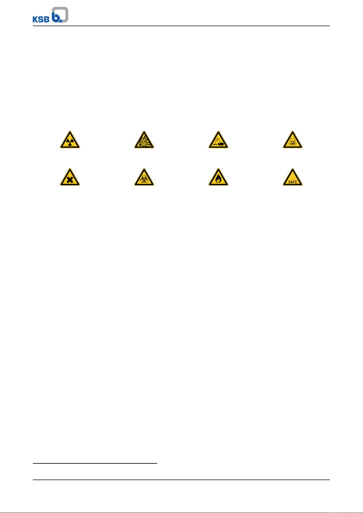
Please tick where applicable
10)
:
Radioactive Explosive Corrosive Toxic
Harmful Bio-hazardous Highly flammable Safe
Reason for return
10)
: ................................................................................................................................
Comments: ................................................................................................................................
................................................................................................................................
The product/accessories have been carefully drained, cleaned and decontaminated inside and outside prior to dispatch/
placing at your disposal.
We herewith declare that this product is free from hazardous chemicals, biological and radioactive substances.
For mag-drive pumps, the inner rotor unit (impeller, casing cover, bearing ring carrier, plain bearing, inner rotor) has been
removed from the pump and cleaned. In cases of containment shroud leakage, the outer rotor, bearing bracket lantern,
leakage barrier and bearing bracket or adapter have also been cleaned.
For canned motor pumps, the rotor and plain bearing have been removed from the pump for cleaning. In cases of leakage at
the stator can, the stator space has been examined for fluid leakage; if fluid handled has penetrated the stator space, it has
been removed.
No special safety precautions are required for further handling.
The following safety precautions are required for flushing fluids, fluid residues and disposal:
...............................................................................................................................................................
...............................................................................................................................................................
We confirm that the above data and information are correct and complete and that dispatch is effected in accordance with the
relevant legal provisions.
.................................................................... ....................................................... .......................................................
Place, date and signature Address Company stamp
10) Required fields
42 of 44
Ama-Drainer-Box Mini
Page 43

Index
Index
C
Certificate of decontamination42
Commissioning/start-up27, 30
Connections14
D
Design14
Designation13
Disposal12
Drive14
E
Event of damage6
F
Fault/malfunction
Causes and remedies35
I
Impeller type14
Installation14
Intended use8
K
Key to safety symbols/markings7
M
Misuse8
O
Operating limits8
Other applicable documents6
P
Partly completed machinery6
R
Return to supplier11
Returning to service30
S
Safety8
Safety awareness9
Scope of supply15
Shutdown29, 30
Start-up27
W
Warnings7
Warranty claims6
Ama-Drainer-Box Mini
43 of 44
Page 44

KSB SE & Co. KGaA
Johann-Klein-Straße 9 • 67227 Frankenthal (Germany)
Tel. +49 6233 86-0
www.ksb.com
2336.83/05-EN
 Loading...