

KSB Ama-Drainer 4 Series, Ama-Drainer 5 Series Operating Manual
Submersible Waste Water Pump
Ama-Drainer 4../5..
Installation/Operating Manual

Legal information/Copyright
Installation/Operating Manual Ama-Drainer 4../5..
Original operating manual
All rights reserved. The contents provided herein must neither be distributed, copied, reproduced,
edited or processed for any other purpose, nor otherwise transmitted, published or made available to a
third party without the manufacturer's express written consent.
Subject to technical modification without prior notice.
© KSB SE & Co. KGaA, Frankenthal 12/03/2019

Contents
Contents
Glossary .................................................................................................................................................. 5
1 General.................................................................................................................................................... 6
1.1 Principles ...........................................................................................................................................................6
1.2 Installation of partly completed machinery....................................................................................................6
1.3 Target group.....................................................................................................................................................6
1.4 Other applicable documents............................................................................................................................6
1.5 Symbols .............................................................................................................................................................6
1.6 Key to safety symbols/markings.......................................................................................................................7
2 Safety...................................................................................................................................................... 8
2.1 General..............................................................................................................................................................8
2.2 Intended use .....................................................................................................................................................8
2.2.1 Prevention of foreseeable misuse.......................................................................................................8
2.3 Personnel qualification and training...............................................................................................................8
2.4 Consequences and risks caused by non-compliance with this manual .........................................................9
2.5 Safety awareness ..............................................................................................................................................9
2.6 Safety information for the operator/user.......................................................................................................9
2.7 Safety information for maintenance, inspection and installation ................................................................9
2.8 Unauthorised modes of operation................................................................................................................10
3 Transport/Temporary Storage/Disposal............................................................................................. 11
3.1 Checking the condition upon delivery..........................................................................................................11
3.2 Transport.........................................................................................................................................................11
3.3 Storage/preservation......................................................................................................................................11
3.4 Return to supplier...........................................................................................................................................11
3.5 Disposal ...........................................................................................................................................................12
4 Description of the Pump (Set)............................................................................................................. 13
4.1 General description ........................................................................................................................................13
4.2 Designation.....................................................................................................................................................14
4.3 Name plate......................................................................................................................................................15
4.4 Design details..................................................................................................................................................15
4.5 Configuration and function...........................................................................................................................17
4.6 Scope of supply...............................................................................................................................................18
4.7 Noise characteristics .......................................................................................................................................18
4.8 Dimensions and weights ................................................................................................................................18
5 Installation at Site................................................................................................................................ 19
5.1 Safety regulations...........................................................................................................................................19
5.2 Checks to be carried out prior to installation...............................................................................................19
5.2.1 Checking the operating data ............................................................................................................19
5.2.2 Preparing the place of installation ...................................................................................................19
5.3 Installing the pump set ..................................................................................................................................20
5.4 Piping ..............................................................................................................................................................20
5.4.1 Connecting the piping.......................................................................................................................20
5.5 Electrical system..............................................................................................................................................21
5.5.1 Information for planning the control system ..................................................................................21
5.5.2 Setting the overload protection device............................................................................................22
5.5.3 Connecting the level control equipment .........................................................................................22
5.5.4 Connection to power supply .............................................................................................................23
5.6 Checking the direction of rotation................................................................................................................23
6 Commissioning/Start-up/Shutdown................................................................................................... 25
6.1 Commissioning/Start-up.................................................................................................................................25
6.1.1 Prerequisites for commissioning/start-up .........................................................................................25
6.1.2 Start-up/shutdown.............................................................................................................................25
Ama-Drainer 4../5..
3 of 60

Contents
6.2 Operating limits..............................................................................................................................................26
6.2.1 Frequency of starts.............................................................................................................................26
6.2.2 Operation on the power supply network ........................................................................................26
6.2.3 Fluid handled .....................................................................................................................................27
6.3 Shutdown/storage/preservation ....................................................................................................................29
6.3.1 Measures to be taken for shutdown ................................................................................................29
6.4 Returning to service .......................................................................................................................................29
7 Servicing/Maintenance........................................................................................................................ 30
7.1 Safety regulations...........................................................................................................................................30
7.2 Servicing/inspection........................................................................................................................................30
7.3 Drainage/disposal ...........................................................................................................................................30
7.4 Dismantling the pump set..............................................................................................................................31
7.5 Reassembling the pump set...........................................................................................................................33
7.6 Tightening torques.........................................................................................................................................34
7.7 Recommended spare parts stock...................................................................................................................34
8 Trouble-shooting.................................................................................................................................. 35
9 Related Documents.............................................................................................................................. 37
9.1 General assembly drawing with list of components ....................................................................................37
9.1.1 General assembly drawing of Ama-Drainer .../10, .../10K, .../35......................................................37
9.1.2 General assembly drawing Ama-Drainer 522/11..............................................................................40
9.2 Dimensions and connections .........................................................................................................................42
9.2.1 Single pumps......................................................................................................................................42
9.2.2 Examples of transportable models ...................................................................................................45
9.2.3 Examples of stationary installation...................................................................................................47
9.2.4 Installation example of a dual-pump station...................................................................................49
9.3 Wiring diagrams .............................................................................................................................................50
9.3.1 Ama-Drainer SE..................................................................................................................................50
9.3.2 Ama-Drainer NE .................................................................................................................................51
9.3.3 Ama-Drainer SD .................................................................................................................................52
9.3.4 Ama-Drainer ND.................................................................................................................................53
10 EU Declaration of Conformity............................................................................................................. 54
11 EU Declaration of Conformity............................................................................................................. 55
12 Certificate of Decontamination........................................................................................................... 56
Index ..................................................................................................................................................... 57
4 of 60
Ama-Drainer 4../5..

Glossary
Glossary
Backflow
Waste water flowing back from the sewer into the
connected drainage piping
Certificate of decontamination
A certificate of decontamination is enclosed by the
customer when returning the product to the
manufacturer to certify that the product has been
properly drained to eliminate any environmental
and health hazards arising from components in
contact with the fluid handled.
Close-coupled design
Motor directly fitted to the pump via a flange or a
drive lantern
Discharge line
Pipe for transporting waste water to a level above
the flood level into the sewer system
DOL starting
For low power ratings (usually up to 4kW), the
three-phase motor is connected directly to the
mains voltage.
submerged. They may be operated outside the
fluid for short periods of time, until the minimum
fluid level has been reached.
Waste water
Water consisting of a combination of water
discharged from households, industrial and other
businesses as well as surface water.
EN 12050-2
European Standard for waste water lifting units
which are used to dispose of faeces-free waste
water occurring below the flood level of buildings
and sites. It defines general requirements as well
as principles of construction and testing.
Flood level
Maximum backflow level of waste water in a
drainage system
Hydraulic system
The part of the pump in which the kinetic energy
is converted into pressure energy
Pump
Machine without drive, additional components or
accessories
Pump set
Complete pump set consisting of pump, drive,
additional components and accessories
Submersible motor pump
Submersible motor pumps are floodable, closecoupled units which are not self-priming. The
pumps are usually operated completely
Ama-Drainer 4../5..
5 of 60
1 General
1 General
1.1 Principles
This operating manual is valid for the type series and variants indicated on the front
cover.
The operating manual describes the proper and safe use of this equipment in all
phases of operation.
The name plate indicates the type series, the main operating data and the serial
number. The serial number uniquely describes the product and is used as
identification in all further business processes.
In the event of damage, immediately contact your nearest KSB Service centre to
maintain the right to claim under warranty.
1.2 Installation of partly completed machinery
To install partly completed machinery supplied by KSB refer to the sub-sections under
Servicing/Maintenance.
1.3 Target group
This operating manual is aimed at the target group of trained and qualified specialist
technical personnel. (ðSection2.3,Page8)
1.4 Other applicable documents
Table1: Overview of other applicable documents
Document Contents
Sub-supplier product literature Operating manuals and other product literature
describing accessories and integrated machinery
components
For accessories and/or integrated machinery components observe the product
literature of the relevant manufacturer.
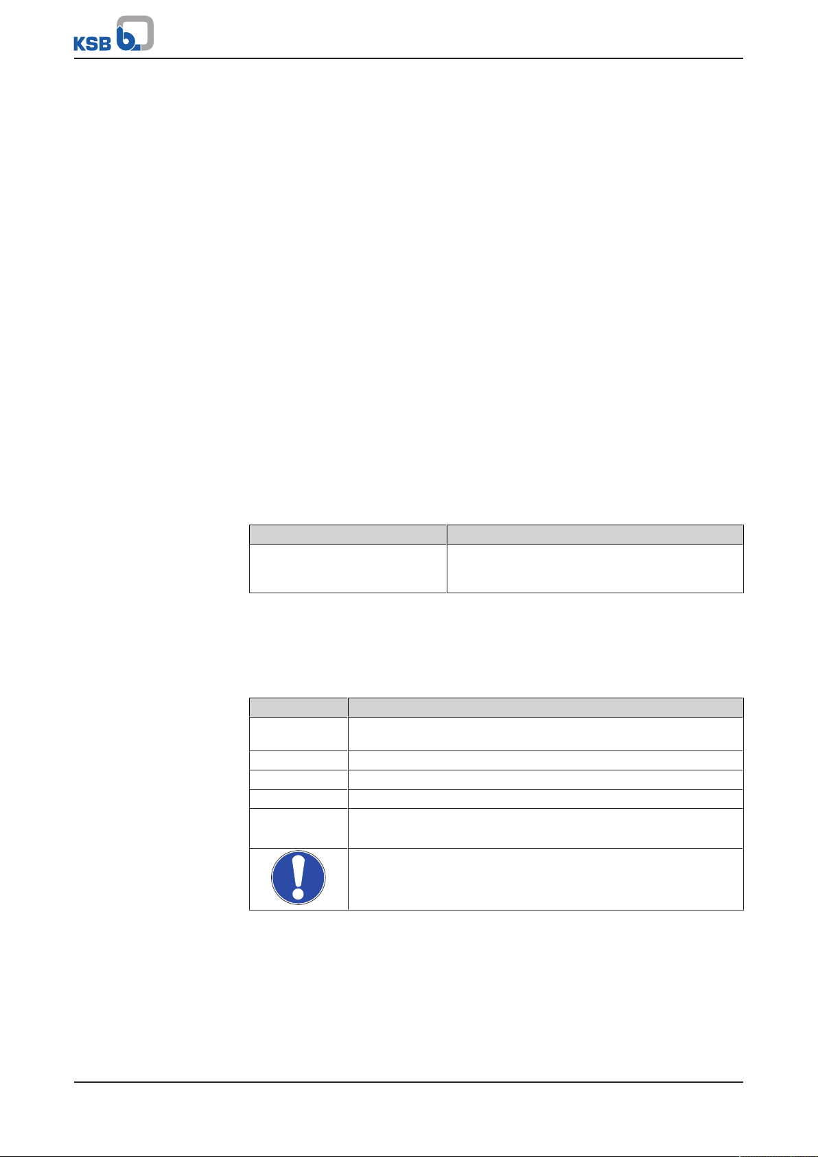
1.5 Symbols
Table2: Symbols used in this manual
Symbol Description
✓ Conditions which need to be fulfilled before proceeding with the
step-by-step instructions
⊳ Safety instructions
⇨
⇨ Cross-references
1.
2.
Result of an action
Step-by-step instructions
Note
Recommendations and important information on how to handle
the product
6 of 60
Ama-Drainer 4../5..
1 General
!
DANGER
!
WARNING
CAUTION
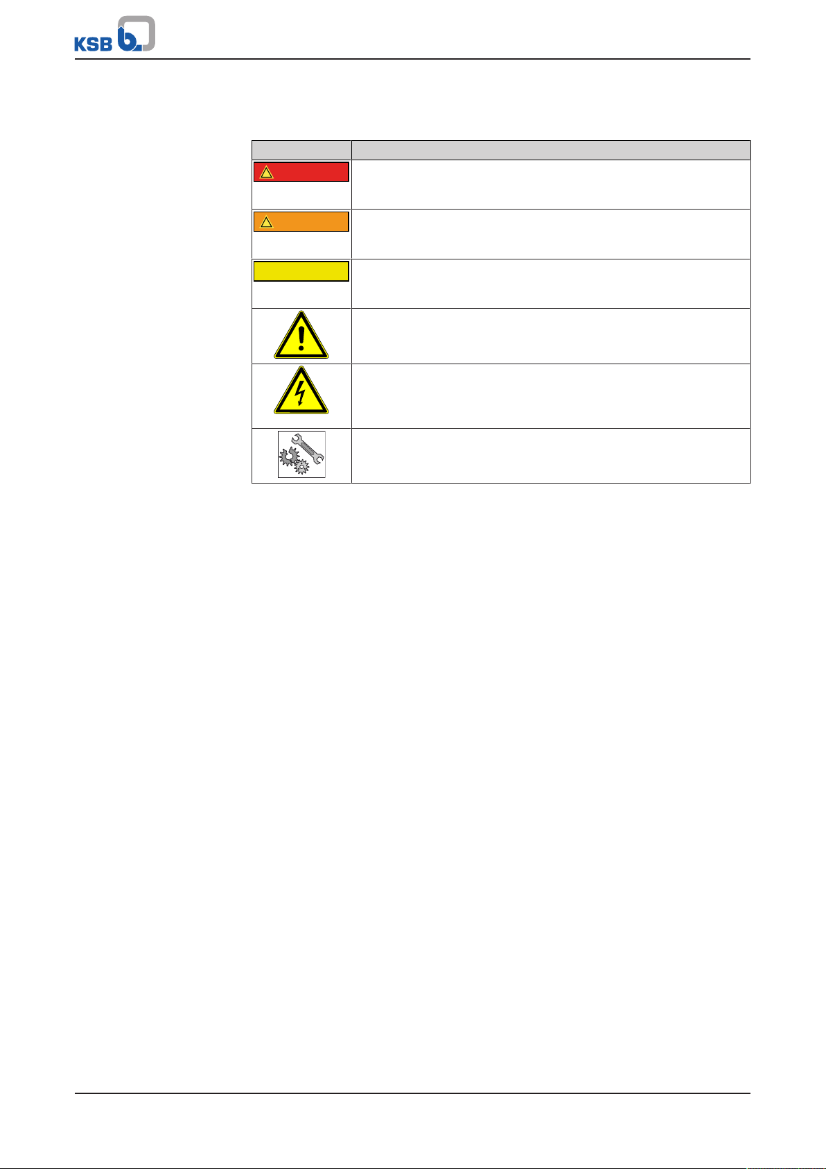
1.6 Key to safety symbols/markings
Table3: Definition of safety symbols/markings
Symbol Description
DANGER
This signal word indicates a high-risk hazard which, if not avoided,
will result in death or serious injury.
WARNING
This signal word indicates a medium-risk hazard which, if not
avoided, could result in death or serious injury.
CAUTION
This signal word indicates a hazard which, if not avoided, could
result in damage to the machine and its functions.
General hazard
In conjunction with one of the signal words this symbol indicates a
hazard which will or could result in death or serious injury.
Electrical hazard
In conjunction with one of the signal words this symbol indicates a
hazard involving electrical voltage and identifies information about
protection against electrical voltage.
Machine damage
In conjunction with the signal word CAUTION this symbol indicates
a hazard for the machine and its functions.
Ama-Drainer 4../5..
7 of 60

2 Safety
!
DANGER
2 Safety
All the information contained in this section refers to hazardous situations.
In addition to the present general safety information the action-related safety
information given in the other sections must be observed.
2.1 General
▪ This operating manual contains general installation, operating and maintenance
instructions that must be observed to ensure safe operation of the system and
prevent personal injury and damage to property.
▪ Comply with all the safety instructions given in the individual sections of this
operating manual.
▪ The operating manual must be read and understood by the responsible specialist
personnel/operators prior to installation and commissioning.
▪ The contents of this operating manual must be available to the specialist
personnel at the site at all times.
▪ Information and markings attached directly to the product must always be
complied with and kept in a perfectly legible condition at all times. This applies
to, for example:
– Arrow indicating the direction of rotation
– Markings for connections
– Name plate
▪ The operator is responsible for ensuring compliance with all local regulations not
taken into account.
2.2 Intended use
▪ The pump (set) must only be operated in the fields of application and within the
use limits specified in the other applicable documents.
▪ Only operate pumps/pump sets which are in perfect technical condition.
▪ Do not operate the pump (set) in partially assembled condition.
▪ Only use the pump to handle the fluids described in the data sheet or product
literature of the pump model or variant.
▪ Never operate the pump without the fluid to be handled.
▪ Observe the minimum flow rates indicated in the data sheet or product literature
(to prevent overheating, bearing damage, etc).
▪ Observe the minimum flow rate and maximum flow rate indicated in the data
sheet or product literature (to prevent overheating, mechanical seal damage,
cavitation damage, bearing damage, etc).
▪ Do not throttle the flow rate on the suction side of the pump (to prevent
cavitation damage).
▪ Consult the manufacturer about any use or mode of operation not described in
the data sheet or product literature.
2.2.1 Prevention of foreseeable misuse
▪ Observe all safety information and instructions in this manual.
▪ Never exceed the permissible application and operating limits specified in the
data sheet or product literature regarding pressure, temperature, etc.
8 of 60
2.3 Personnel qualification and training
All personnel involved must be fully qualified to transport, install, operate, maintain
and inspect the machinery this manual refers to.
The responsibilities, competence and supervision of all personnel involved in
transport, installation, operation, maintenance and inspection must be clearly
defined by the operator.
Ama-Drainer 4../5..

2 Safety
Deficits in knowledge must be rectified by means of training and instruction
provided by sufficiently trained specialist personnel. If required, the operator can
commission the manufacturer/supplier to train the personnel.
Training on the pump (set) must always be supervised by technical specialist
personnel.
2.4 Consequences and risks caused by non-compliance with this manual
▪ Non-compliance with these operating instructions will lead to forfeiture of
warranty cover and of any and all rights to claims for damages.
▪ Non-compliance can, for example, have the following consequences:
– Hazards to persons due to electrical, thermal, mechanical and chemical
effects and explosions
– Failure of important product functions
– Failure of prescribed maintenance and servicing practices
– Hazard to the environment due to leakage of hazardous substances
2.5 Safety awareness
In addition to the safety information contained in this operating manual and the
intended use, the following safety regulations shall be complied with:
▪ Accident prevention, health regulations and safety regulations
▪ Explosion protection regulations
▪ Safety regulations for handling hazardous substances
▪ Applicable standards, directives and laws
2.6 Safety information for the operator/user
▪ Fit protective equipment (e.g. contact guards) supplied by the operator for hot,
cold or moving parts, and check that the equipment functions properly.
▪ Do not remove any protective equipment (e.g. contact guards) during operation.
▪ Provide the personnel with protective equipment and make sure it is used.
▪ Contain leakages (e.g. at the shaft seal) of hazardous fluids handled (e.g.
explosive, toxic, hot) so as to avoid any danger to persons and the environment.
Adhere to all relevant laws.
▪ Eliminate all electrical hazards. (In this respect refer to the applicable national
safety regulations and/or regulations issued by the local energy supply
companies.)
▪ If shutting down the pump does not increase potential risk, fit an emergency-
stop control device in the immediate vicinity of the pump (set) during pump set
installation.
▪ Make sure the system cannot be accessed by unauthorised persons (e.g. children).
2.7 Safety information for maintenance, inspection and installation
▪ Modifications or alterations of the pump (set) are only permitted with the
manufacturer's prior consent.
▪ Use only original spare parts or parts/components authorised by the
manufacturer. The use of other parts/components can invalidate any liability of
the manufacturer for resulting damage.
▪ The operator ensures that maintenance, inspection and installation are
performed by authorised, qualified specialist personnel who are thoroughly
familiar with the manual.
▪ Only carry out work on the pump (set) during standstill of the pump.
▪ Only perform work on the pump set when it has been disconnected from the
power supply (de-energised).
▪ The pump (set) must have cooled down to ambient temperature.
Ama-Drainer 4../5..
9 of 60

2 Safety
▪ Pump pressure must have been released and the pump must have been drained.
▪ When taking the pump set out of service always adhere to the procedure
described in the manual. (ðSection6.3,Page29)
▪ Decontaminate pumps which handle fluids posing a health hazard.
▪ As soon as the work has been completed, re-install and re-activate any safety-
relevant devices and protective devices. Before returning the product to service,
observe all instructions on commissioning. (ðSection6.1,Page25)
2.8 Unauthorised modes of operation
Never operate the pump (set) outside the limits stated in the data sheet and in this
manual.
The warranty relating to the operating reliability and safety of the supplied pump
(set) is only valid if the equipment is used in accordance with its intended use.
10 of 60
Ama-Drainer 4../5..
3 Transport/Temporary Storage/Disposal
3 Transport/Temporary Storage/Disposal
3.1 Checking the condition upon delivery
1. On transfer of goods, check each packaging unit for damage.
2. In the event of in-transit damage, assess the exact damage, document it and
notify KSB or the supplying dealer and the insurer about the damage in writing
immediately.
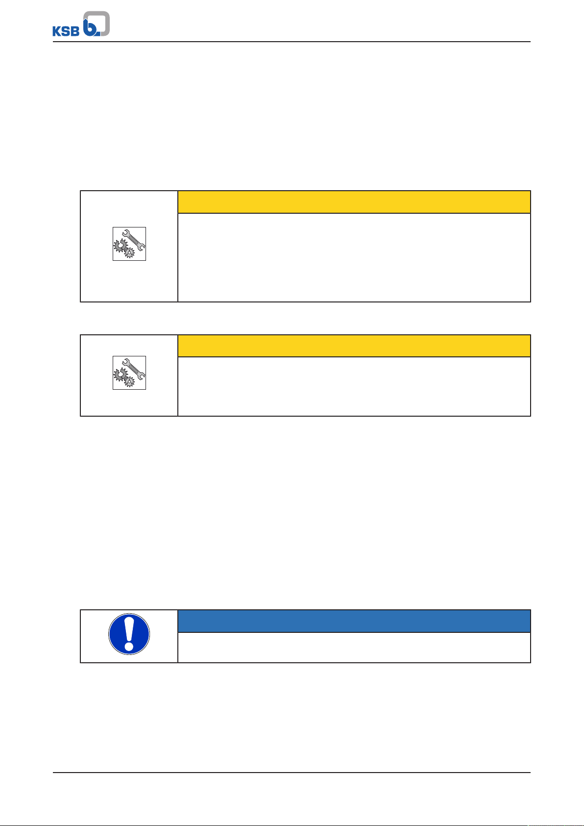
3.2 Transport
CAUTION
Improper pump transport
Damage to the pump!
▷ To transport the pump/pump set always use the handle provided.
▷ Never suspend the pump (set) from the float switch (type SE only) or the power
supply cable for transport.
▷ Prevent the pump (set) from getting knocked or dropped.
3.3 Storage/preservation
CAUTION
Damage during storage due to frost, humidity, dirt, UV radiation or vermin
Corrosion/contamination of the pump!
▷ Store the pump (set) in a dry, dark, frost-proof room not exposed to sunlight
where the atmospheric humidity is as constant as possible.
Store the pump (set) vertically in a dry, dark, frost-proof room not exposed to
sunlight. Under these conditions it does not need additional preservation.
3.4 Return to supplier
1. Drain the pump as per operating instructions.
2. Always flush and clean the pump, particularly if it has been used for handling
noxious, hot or other hazardous fluids.
3. If the fluids handled by the pump (set) leave residues which might lead to
corrosion when coming into contact with atmospheric humidity, or which might
ignite when coming into contact with oxygen, the pump set must be
neutralised, and anhydrous inert gas must be blown through the pump for
drying purposes.
4. Always complete and enclose a certificate of decontamination when returning
the pump (set). (ðSection12,Page56)
Always indicate any safety and decontamination measures taken.
NOTE
If required, a blank certificate of decontamination can be downloaded from the
following web site: www.ksb.com/certificate_of_decontamination
Ama-Drainer 4../5..
11 of 60

3 Transport/Temporary Storage/Disposal
3.5 Disposal
WARNING
Fluids, consumables and supplies posing a health hazard
Hazard to persons and the environment!
▷ Collect and dispose of any preservatives, flushing liquids and fluid residues.
▷ Wear safety clothing and a protective mask, if required.
▷ Observe all legal regulations on the disposal of fluids posing a health hazard.
1. Dismantle the product.
Collect greases and other lubricants during dismantling.
2. Separate and sort the materials, e.g. by:
- Metals
- Plastics
- Electronic waste
- Greases and other lubricants
3. Dispose of materials in accordance with local regulations or in another
controlled manner.
Electrical or electronic equipment marked with the adjacent symbol must not be
disposed of in household waste at the end of its service life.
Contact your local waste disposal partner for returns.
If the used electrical or electronic equipment contains personal data, the user is
responsible for deleting it before the equipment is returned.
12 of 60
Ama-Drainer 4../5..

4 Description of the Pump (Set)
4 Description of the Pump (Set)
4.1 General description
▪ Submersible waste water pump (see submersible motor pump)
Variant A (standard design)
▪ Chemically neutral waste water
▪ Slightly contaminated waste water (up to 40°C max.)
▪ Wash water (up to 90 °C max. for short periods t ≤ 3minutes)
Free passage 10/11mm:
▪ Solid particles with a particle size of up to 10 or 11mm
Free passage 35mm:
▪ Waste water containing long fibres and stringy material
▪ Solid particles with a particle size of up to 35mm
Variant C for aggressive fluids
In addition to standard variant:
▪ Swimming pool water
▪ Brackish water
▪ Seawater
▪ Water containing salt
▪ Aggressive fluids
▪ Condensate from heat recovery applications
1)
Variant R (for water containing oil / oil emulsions)
In addition to standard variant:
▪ Oil emulsions and cutting oils
▪ Waste water containing oil
1) Swimming pool water (0.4 to 1.4mg/l free chlorine, max.0.6mg/l combined chlorine, pH6.9 to 7.7, water hardness 10 to
30°dH, max. salt content 7g/l)
Ama-Drainer 4../5..
13 of 60
4 Description of the Pump (Set)
4.2 Designation
Example: Ama-DrainerA422SD/10K
Table4: Designation key
Code Description
Ama-Drainer Type series
A Material variant
A Standard variant
C Variant for aggressive water
R Variant for water containing oil / oil emulsions
4 Nominal discharge nozzle diameter
4 ~ 40mm (G 11/2)
5 ~ 50mm (G 2)
22 Motor rating [kW x 10]
05 0.55kW
07 0.75 kW
11 1.1 kW
15 1.5 kW
22 2.2 kW
S Float switch
S With float switch
N Without float switch
D Motor
D Three-phase motor
E Single-phase alternating current
10 Free passage [mm]
10 10mm
11 11mm
35 35mm
K Cooling jacket
K With cooling jacket
2)
-
Without cooling jacket
2) Blank
14 of 60
Ama-Drainer 4../5..
4 Description of the Pump (Set)
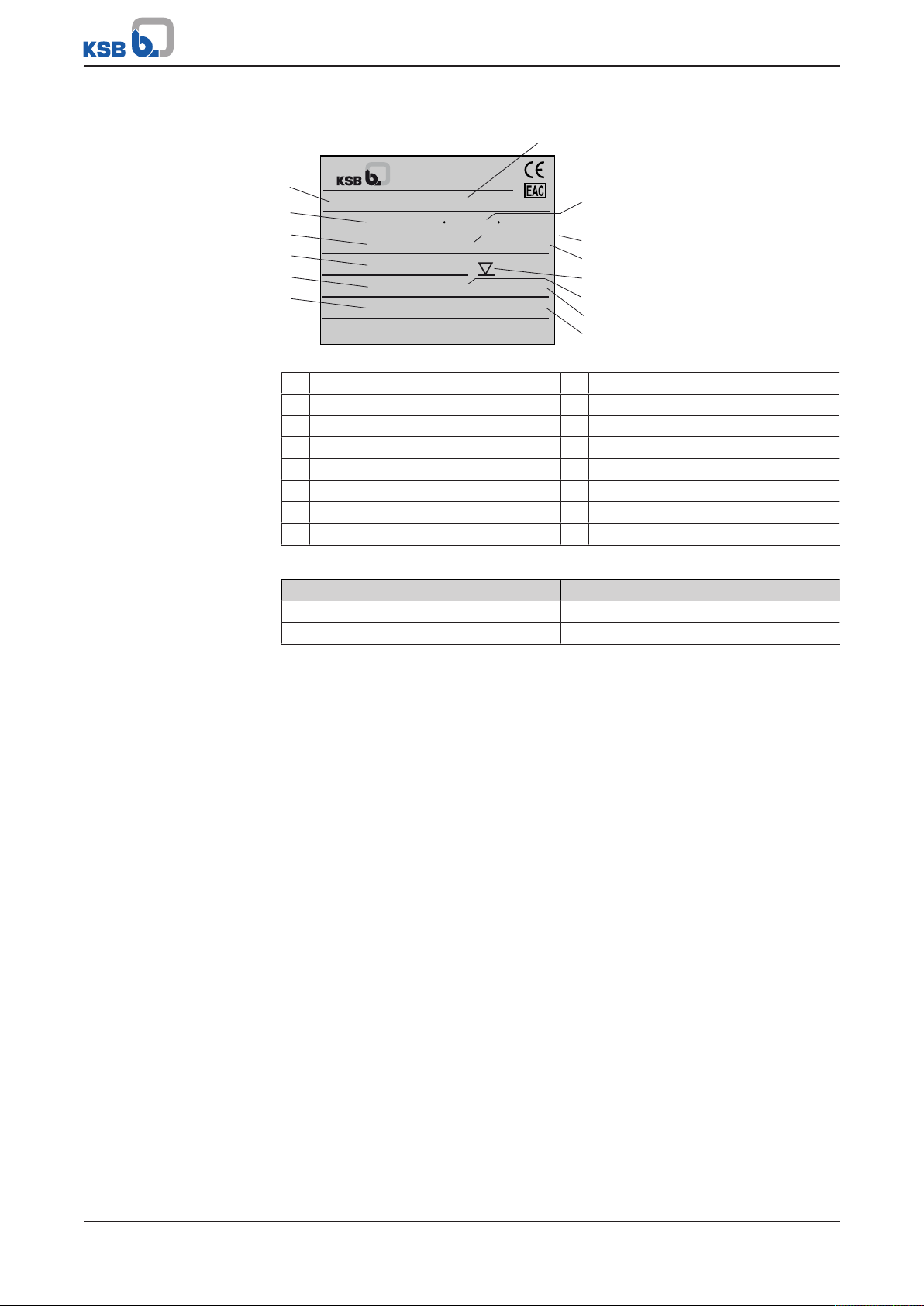
220-240 V ~ 50 Hz T40°C
AMA-DRAINER A 507 SE/10K
Made in Germany
0,75 kW 5,5 A classe F
2-25 m³/h
11,6-3,2 m IP 68 7m 14,7kg
EN12050-2 2016w16
Johann-Klein-Straße 9
Deutschland
67227 Frankenthal
KSB SE & Co. KGaA
1
2
5
4
3
6
10
9
12
11
8
13
15
14
7
4.3 Name plate
Fig.1: Name plate (example)
1 Type series, size 9 Maximum fluid temperature
2 Rated voltage 10 Rated current
3 Rated pump power output 11 Thermal class of winding insulation
4 Flow rate (Q
5 Head (H
6 Principles of construction and testing 14 Total weight
7 Cable version (e.g. E= single-phase) 15 Year of production (serial number)
8 Rated frequency
min.
/ Q
min.
/ H
) 12 Maximum immersion depth
max.
) 13 Enclosure
max.
Table5: Key to the serial number
Code Description
2016 Calendar year
16 Calendar week
4.4 Design details
Design
▪ Fully floodable submersible motor pump
▪ Close-coupled design
▪ Single-stage
▪ To EN 12050-2
▪ Vertical discharge nozzle
▪ With or without level control
Installation
▪ Vertical installation
▪ Wet-installed transportable model
▪ Wet-installed stationary model
Drive
▪ Motor winding to IEC60038
▪ Motor design to EN60043T1/IEC34-1
▪ Thermal class F
▪ DOL starting
▪ Enclosure IP68 (permanently submerged) to EN60529/ IEC529
Ama-Drainer 4../5..
15 of 60

4 Description of the Pump (Set)
Ama-Drainer NE/SE 10/35:
▪ AC motor
▪ Integrated temperature switch
▪ 10-metre power cable
▪ Shockproof plug
Ama-Drainer SD 10/11/35:
▪ Three-phase motor
▪ Integrated temperature switch
▪ 10-metre power cable
▪ CEE plug (3L+PE+N) with motor contactor and phase inverter
Ama-Drainer ND 10/11/35:
▪ Three-phase motor
▪ Integrated temperature switch
▪ 10-metre power cable with free cable end and protective cap
Shaft seal
▪ Pump end, 1 bi-directional mechanical seal
▪ Drive end: 1 shaft seal ring
▪ Liquid reservoir between the seals for cooling and lubrication
Impeller type
▪ Open multi-vane impeller
▪ Free-flow impeller
Bearings
▪ Maintenance-free
▪ Grease-packed rolling element bearings sealed for life
16 of 60
Ama-Drainer 4../5..
4 Description of the Pump (Set)
1
3
2
4
5
6
7
8
9
10
11
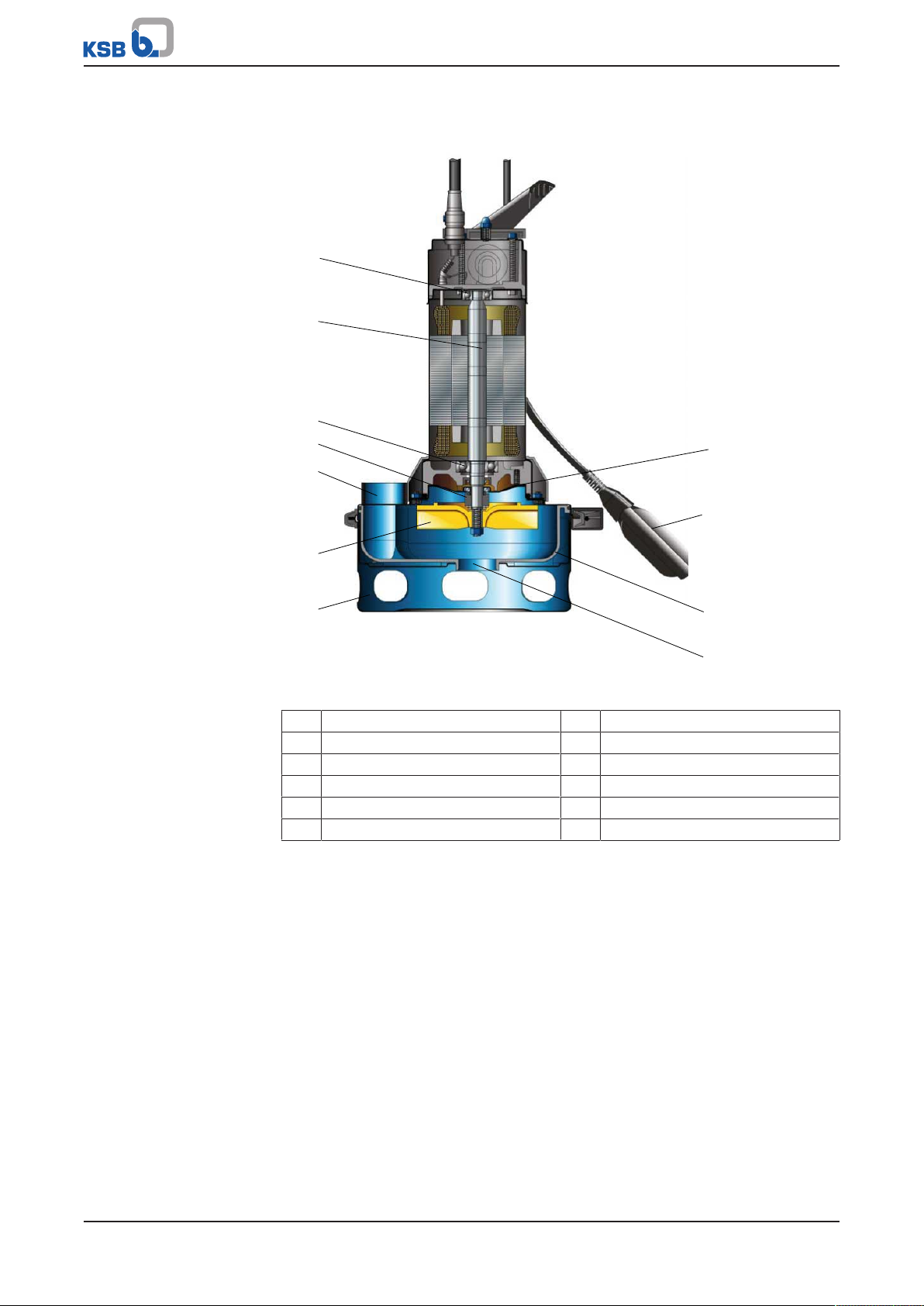
4.5 Configuration and function
Fig.2: Sectional drawing
1 Bearing, motor end 2 Shaft
3 Bearing, pump end 4 Shaft seal
5 Discharge nozzle 6 Impeller
7 Foot 8 Pump casing
9 Float switch 10 Volute casing
11 Suction nozzle
Design The pump is designed with a vertical fluid inlet and a vertical outlet. The hydraulic
Function The fluid enters the pump axially via the suction nozzle (11) and is accelerated
system sits on the extended motor shaft. The shaft runs in common bearings.
outward by the rotating impeller (6). In the flow passage of the volute casing (10) the
kinetic energy of the fluid is converted into pressure energy. The fluid is pumped to
the discharge nozzle (5), where it leaves the pump. At the rear side of the impeller,
the shaft (2) enters the pump casing (8) which houses the hydraulic system. The shaft
passage through the pump casing is sealed to atmosphere with a shaft seal (4). The
shaft runs in rolling element bearings (1) and (3).
Ama-Drainer 4../5..
17 of 60

4 Description of the Pump (Set)
4.6 Scope of supply
Depending on the model, the following items are included in the scope of supply:
▪ Pump set
▪ Connection socket or discharge elbow with internal thread
▪ 10-metre power cable
For ... SE / ... SD:
▪ Float switch
Accessories
▪ Control units for proper operation of the pump sets
4.7 Noise characteristics
Sound pressure level < 70 dB(A)
4.8 Dimensions and weights
For dimensions and weights refer to the general arrangement drawing/outline
drawing or data sheet of the pump set.
18 of 60
Ama-Drainer 4../5..
 Loading...