

KSB Amacan P 1200-870, Amacan P series, Amacan P 1500-1060, Amacan P 1600-1060, Amacan P 900-540 Installation & Operating Manual
...Page 1
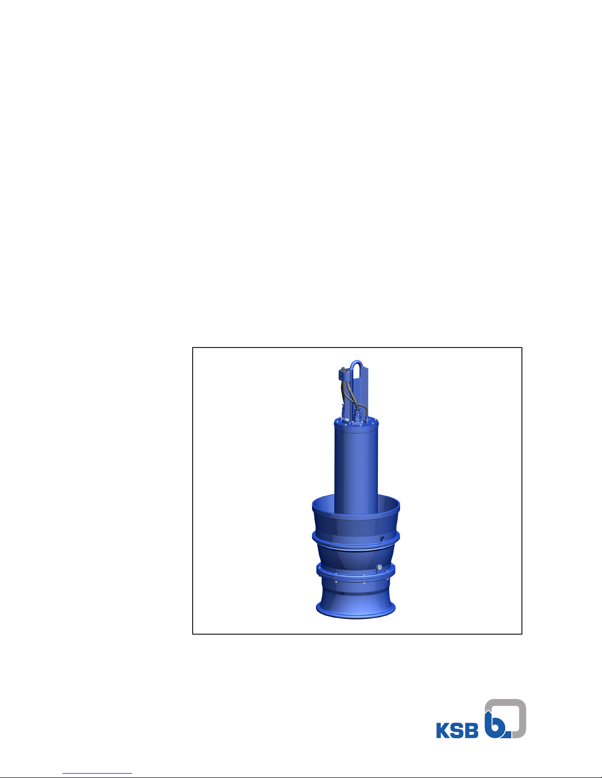
Submersible Pump in Discharge Tube
Amacan P
50 Hz
Amacan P 700 - 470
Amacan P 800/900 - 540
Amacan P 1000 - 700
Amacan P 1200 - 870
Amacan P 1500/1600 - 1060
Installation/Operating Manual
Mat. No.: 01137299
Page 2

Legal information/Copyright
Installation/Operating Manual Amacan P
Original operating manual
All rights reserved. The contents provided herein must neither be distributed, copied, reproduced,
edited or processed for any other purpose, nor otherwise transmitted, published or made available to a
third party without the manufacturer's express written consent.
Subject to technical modification without prior notice.
© KSB SE & Co. KGaA, Frankenthal 03/09/2018
Page 3

Contents
3 of 132
Amacan P
Contents
1 General.................................................................................................................................................... 7
1.1 Principles ...........................................................................................................................................................7
1.2 Installation of partly completed machinery....................................................................................................7
1.3 Target group.....................................................................................................................................................7
1.4 Other applicable documents............................................................................................................................7
1.5 Symbols .............................................................................................................................................................7
2 Safety...................................................................................................................................................... 8
2.1 Key to safety symbols/markings.......................................................................................................................8
2.2 General..............................................................................................................................................................8
2.3 Intended use .....................................................................................................................................................9
2.4 Personnel qualification and training...............................................................................................................9
2.5 Consequences and risks caused by non-compliance with this manual .........................................................9
2.6 Safety awareness ..............................................................................................................................................9
2.7 Safety information for the operator/user.......................................................................................................9
2.8 Safety information for maintenance, inspection and installation ..............................................................10
2.9 Unauthorised modes of operation................................................................................................................10
2.10 Explosion protection ......................................................................................................................................10
2.10.1 Repair..................................................................................................................................................11
3 Transport/Temporary Storage/Disposal............................................................................................. 12
3.1 Checking the condition upon delivery..........................................................................................................12
3.2 Transport.........................................................................................................................................................12
3.2.1 Transporting the delivered pump to the place of installation .......................................................12
3.2.2 Placing the pump set in a vertical or horizontal position ...............................................................12
3.2.3 Transporting the pump set................................................................................................................14
3.2.4 Transport lock ....................................................................................................................................15
3.3 Storage/preservation......................................................................................................................................15
3.4 Return to supplier...........................................................................................................................................16
3.5 Disposal ...........................................................................................................................................................17
4 Description of the Pump (Set)............................................................................................................. 18
4.1 General description ........................................................................................................................................18
4.2 Designation.....................................................................................................................................................18
4.3 Name plate......................................................................................................................................................18
4.4 Design details..................................................................................................................................................19
4.5 Installation types ............................................................................................................................................19
4.6 Configuration and function...........................................................................................................................20
4.7 Scope of supply...............................................................................................................................................21
4.8 Dimensions and weights ................................................................................................................................21
5 Installation at Site................................................................................................................................ 22
5.1 Safety regulations...........................................................................................................................................22
5.2 Checks to be carried out prior to installation...............................................................................................22
5.2.1 Checking the structural requirements ..............................................................................................22
5.2.2 Checking the operating data ............................................................................................................22
5.2.3 Checking the lubricant of the mechanical seal ................................................................................22
5.2.4 Checking the direction of rotation ...................................................................................................23
5.3 Lowering the pump set into the discharge tube..........................................................................................25
5.3.1 Information for correct installation..................................................................................................26
5.3.2 Installation without support rope ....................................................................................................26
5.3.3 Installation with a support rope .......................................................................................................27
5.3.4 Installation with a support rope and support spacer ......................................................................30
5.4 Electrical system..............................................................................................................................................35
5.4.1 Information for planning the control system ..................................................................................35
5.4.2 Electrical connection..........................................................................................................................41
Page 4

Contents
4 of 132
Amacan P
6 Commissioning/Start-up/Shutdown................................................................................................... 43
6.1 Commissioning/Start-up.................................................................................................................................43
6.1.1 Prerequisites for commissioning/start-up .........................................................................................43
6.1.2 Start-up...............................................................................................................................................44
6.2 Operating limits..............................................................................................................................................44
6.2.1 Operation on the power supply mains.............................................................................................44
6.2.2 Frequency of starts.............................................................................................................................45
6.2.3 Operation on a frequency inverter...................................................................................................45
6.2.4 Fluid handled .....................................................................................................................................45
6.3 Shutdown/storage/preservation ....................................................................................................................47
6.3.1 Shutdown ...........................................................................................................................................47
6.3.2 Measures to be taken for shutdown ................................................................................................47
6.4 Returning to service .......................................................................................................................................48
7 Servicing/Maintenance........................................................................................................................ 49
7.1 Safety regulations...........................................................................................................................................49
7.2 Maintenance/inspection.................................................................................................................................51
7.2.1 Inspection work..................................................................................................................................51
7.3 Removing the pump set.................................................................................................................................53
7.3.1 Removing the pump set ....................................................................................................................53
7.3.2 Drainage/cleaning..............................................................................................................................54
7.3.3 Checking the cable bundle................................................................................................................54
7.3.4 Checking the earth conductor ..........................................................................................................55
7.3.5 Checking the mechanical seal for leakage .......................................................................................55
7.4 Lubrication and lubricant change .................................................................................................................56
7.4.1 Lubricating the mechanical seal........................................................................................................56
7.4.2 Lubricating the rolling element bearings.........................................................................................59
7.5 Dismantling the pump set..............................................................................................................................60
7.5.1 General information/Safety regulations...........................................................................................60
7.5.2 Preparing the pump set.....................................................................................................................61
7.5.3 Removing the bellmouth...................................................................................................................61
7.5.4 Removing the impeller ......................................................................................................................62
7.5.5 Removing the mechanical seal..........................................................................................................62
7.5.6 Dismantling the motor section .........................................................................................................64
7.6 Reassembling the pump set...........................................................................................................................66
7.6.1 General information/Safety regulations...........................................................................................66
7.6.2 Installing the replacement cable gland ............................................................................................68
7.6.3 Fitting the motor housing cover .......................................................................................................69
7.6.4 Installing the mechanical seal ...........................................................................................................71
7.6.5 Fitting the impeller............................................................................................................................75
7.6.6 Fitting the bellmouth ........................................................................................................................76
7.6.7 Leak testing........................................................................................................................................77
7.7 Checking the electrical connection and motor.............................................................................................79
7.8 Tightening torques.........................................................................................................................................79
7.9 Spare parts stock.............................................................................................................................................80
7.9.1 Ordering spare parts..........................................................................................................................80
7.9.2 Recommended spare parts stock for 2 years' operation to DIN24296 ..........................................80
8 Trouble-shooting.................................................................................................................................. 82
9 Related Documents.............................................................................................................................. 84
9.1 General assembly drawing.............................................................................................................................84
9.1.1 Special features..................................................................................................................................93
9.2 Cable bundle...................................................................................................................................................94
9.3 Wiring diagrams .............................................................................................................................................96
9.3.1 Wiring diagram for the power cable 700-470…1500-1060.............................................................96
9.3.2 Wiring diagram for the power cable 1600-1060..............................................................................97
9.3.3 Wiring diagrams for the sensors .......................................................................................................98
9.4 Flamepaths on explosion-proof motors......................................................................................................102
9.5 Dimensions....................................................................................................................................................103
Page 5

Contents
5 of 132
Amacan P
9.6 Wiring diagrams ...........................................................................................................................................107
9.6.1 Installation type BU .........................................................................................................................107
9.6.2 Installation type BG .........................................................................................................................110
9.6.3 Installation type CU .........................................................................................................................112
9.6.4 Installation type CG .........................................................................................................................115
9.6.5 Installation type DU.........................................................................................................................118
9.6.6 Installation type DG.........................................................................................................................121
9.6.7 Dimensions of the flow-straightening vane...................................................................................124
10 EU Declaration of Conformity........................................................................................................... 126
11 Certificate of Decontamination......................................................................................................... 127
Index ................................................................................................................................................... 128
Page 6

Glossary
6 of 132
Amacan P
Glossary
Certificate of decontamination
A certificate of decontamination is enclosed by the
customer when returning the product to the
manufacturer to certify that the product has been
properly drained to eliminate any environmental
and health hazards arising from components in
contact with the fluid handled.
Close-coupled design
Motor directly fitted to the pump via a flange or a
drive lantern
ECB (ever clean blade) design
Self-cleaning vane profile
Submersible pump in discharge tube
A submersible motor pump which is completely
submerged and suspended in a discharge tube
Page 7
1 General
7 of 132
Amacan P
1 General
1.1 Principles
This operating manual is supplied as an integral part of the type series and variants
indicated on the front cover.
The manual describes the proper and safe use of this equipment in all phases of
operation.
The name plate indicates the type series and size, the main operating data, the order
number and the order item number. The order number and order item number
clearly identify the pump set and serve as identification for all further business
processes.
In the event of damage, immediately contact your nearest KSB Service centre to
maintain the right to claim under warranty.
1.2 Installation of partly completed machinery
To install partly completed machinery supplied by KSB refer to the sub-sections under
Servicing/Maintenance.
1.3 Target group
This operating manual is aimed at the target group of trained and qualified specialist
technical personnel. (ðSection2.4,Page9)
1.4 Other applicable documents
Table1: Overview of other applicable documents
Document Contents
Data sheet Description of the technical data of the pump (set)
Hydraulic characteristic curve Characteristic curves showing head, NPSH
required, efficiency and power input
General assembly drawing
1)
Sectional drawing of the pump set
Sub-supplier product literature1)Operating manuals and other product literature
describing accessories and integrated machinery
components
Spare parts lists
1)
Description of spare parts
For accessories and/or integrated machinery components observe the relevant
manufacturer's product literature.
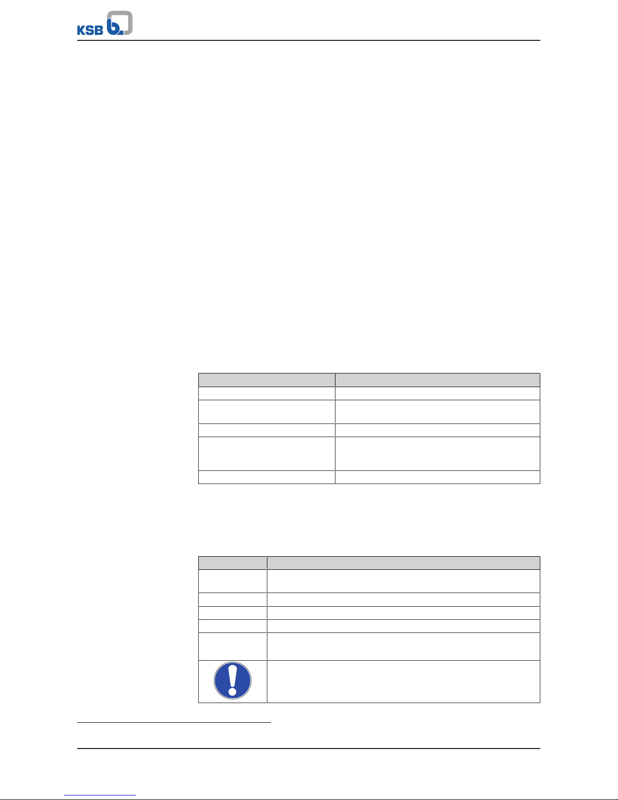
1.5 Symbols
Table2: Symbols used in this manual
Symbol Description
✓ Conditions which need to be fulfilled before proceeding with the
step-by-step instructions
⊳ Safety instructions
⇨
Result of an action
⇨ Cross-references
1.
2.
Step-by-step instructions
Note
Recommendations and important information on how to handle
the product
1) If agreed to be included in the scope of supply
Page 8
2 Safety
8 of 132
Amacan P
2 Safety
!
DANGER
All the information contained in this section refers to hazardous situations.
In addition to the present general safety information the action-related safety
information given in the other sections must be observed.
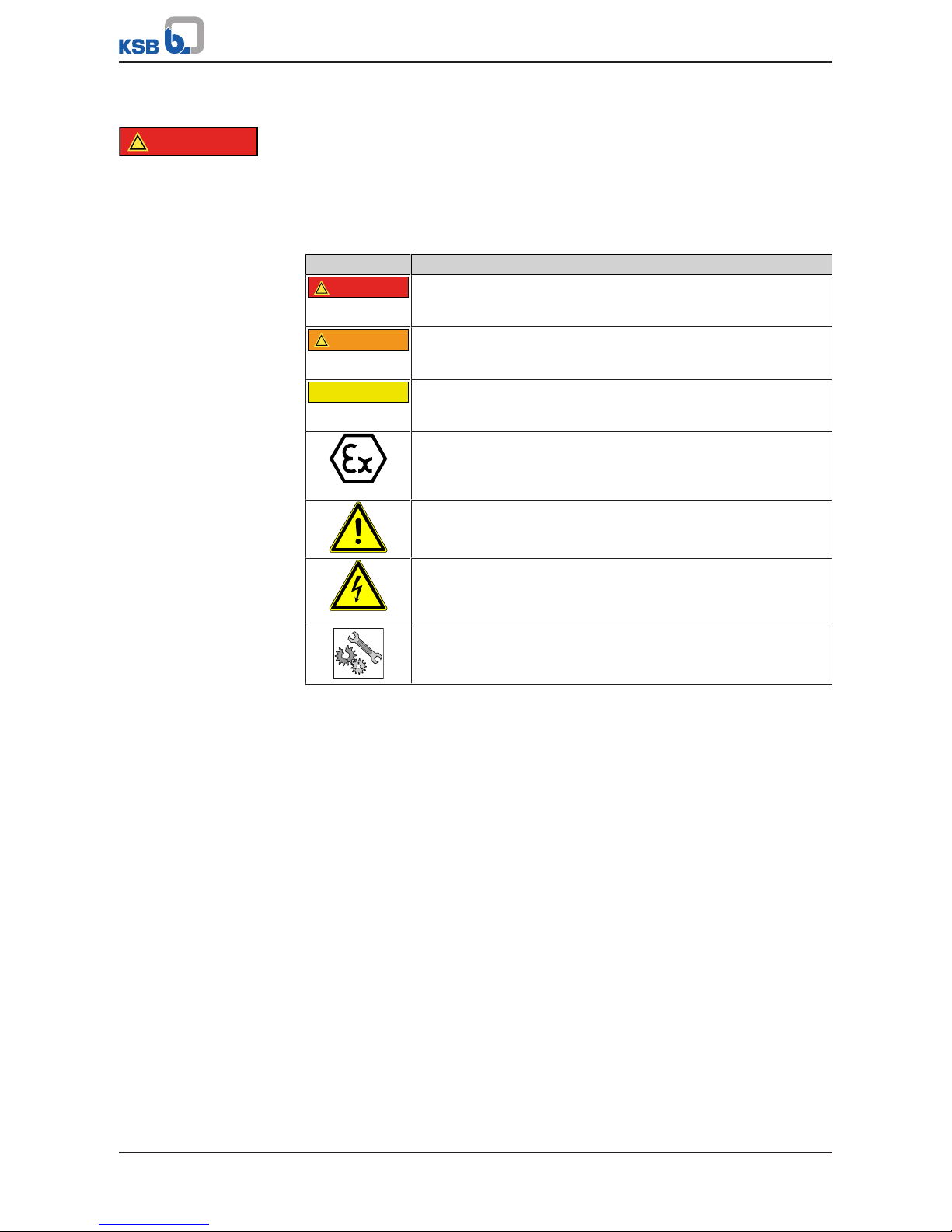
2.1 Key to safety symbols/markings
Table3: Definition of safety symbols/markings
Symbol Description
!
DANGER
DANGER
This signal word indicates a high-risk hazard which, if not avoided,
will result in death or serious injury.
!
WARNING
WARNING
This signal word indicates a medium-risk hazard which, if not
avoided, could result in death or serious injury.
CAUTION
CAUTION
This signal word indicates a hazard which, if not avoided, could
result in damage to the machine and its functions.
Explosion protection
This symbol identifies information about avoiding explosions in
potentially explosive atmospheres in accordance with EU Directive
2014/34/EU (ATEX).
General hazard
In conjunction with one of the signal words this symbol indicates a
hazard which will or could result in death or serious injury.
Electrical hazard
In conjunction with one of the signal words this symbol indicates a
hazard involving electrical voltage and identifies information about
protection against electrical voltage.
Machine damage
In conjunction with the signal word CAUTION this symbol indicates
a hazard for the machine and its functions.
2.2 General
This operating manual contains general installation, operating and maintenance
instructions that must be observed to ensure safe operation of the system and
prevent personal injury and damage to property.
The safety information in all sections of this manual must be complied with.
The operating manual must be read and understood by the responsible specialist
personnel/operators prior to installation and commissioning.
The contents of this operating manual must be available to the specialist personnel
at the site at all times.
Information attached directly to the product must always be complied with and kept
in a perfectly legible condition at all times. This applies to, for example:
▪ Arrow indicating the direction of rotation
▪ Markings for connections
▪ Name plate
The operator is responsible for ensuring compliance with all local regulations not
taken into account in this operating manual.
Page 9

2 Safety
9 of 132
Amacan P
2.3 Intended use
▪ The pump (set) must only be operated in the fields of application and within the
use limits specified in the other applicable documents.
▪ Only operate pumps/pump sets which are in perfect technical condition.
▪ Do not operate the pump (set) in partially assembled condition.
▪ Only use the pump to handle the fluids described in the data sheet or product
literature of the pump model or variant.
▪ Never operate the pump without the fluid to be handled.
▪ Observe the limits for continuous duty specified in the data sheet or product
literature (Q
min
and Q
max
) (to prevent damage such as shaft fracture, bearing
failure, mechanical seal damage, etc).
▪ Observe the minimum flow rate and maximum flow rate indicated in the data
sheet or product literature (to prevent overheating, mechanical seal damage,
cavitation damage, bearing damage, etc).
▪ Always operate the pump (set) in the direction of rotation it is intended for.
2.4 Personnel qualification and training
All personnel involved must be fully qualified to transport, install, operate, maintain
and inspect the machinery this manual refers to.
The responsibilities, competence and supervision of all personnel involved in
transport, installation, operation, maintenance and inspection must be clearly
defined by the operator.
Deficits in knowledge must be rectified by means of training and instruction
provided by sufficiently trained specialist personnel. If required, the operator can
commission the manufacturer/supplier to train the personnel.
Training on the pump (set) must always be supervised by technical specialist
personnel.
2.5 Consequences and risks caused by non-compliance with this manual
▪ Non-compliance with these operating instructions will lead to forfeiture of
warranty cover and of any and all rights to claims for damages.
▪ Non-compliance can, for example, have the following consequences:
– Hazards to persons due to electrical, thermal, mechanical and chemical
effects and explosions
– Failure of important product functions
– Failure of prescribed maintenance and servicing practices
– Hazard to the environment due to leakage of hazardous substances
2.6 Safety awareness
In addition to the safety information contained in this manual and the intended use,
the following safety regulations shall be complied with:
▪ Accident prevention, health regulations and safety regulations
▪ Explosion protection regulations
▪ Safety regulations for handling hazardous substances
▪ Applicable standards, directives and laws
2.7 Safety information for the operator/user
▪ Fit protective equipment (e.g. contact guards) supplied by the operator for hot,
cold or moving parts, and check that the equipment functions properly.
▪ Do not remove any protective equipment (e.g. contact guards) during operation.
▪ Provide the personnel with protective equipment and make sure it is used.
Page 10
2 Safety
10 of 132
Amacan P
▪ Contain leakages (e.g. at the shaft seal) of hazardous fluids handled (e.g.
explosive, toxic, hot) so as to avoid any danger to persons and the environment.
Adhere to all relevant laws.
▪ Eliminate all electrical hazards. (In this respect refer to the applicable national
safety regulations and/or regulations issued by the local energy supply
companies.)
▪ If shutting down the pump does not increase potential risk, fit an emergency-
stop control device in the immediate vicinity of the pump (set) during pump set
installation.
2.8 Safety information for maintenance, inspection and installation
▪ Modifications or alterations of the pump (set) are only permitted with the
manufacturer's prior consent.
▪ Use only original spare parts or parts/components authorised by the
manufacturer. The use of other parts/components can invalidate any liability of
the manufacturer for resulting damage.
▪ The operator ensures that maintenance, inspection and installation is performed
by authorised, qualified specialist personnel who are thoroughly familiar with
the manual.
▪ Only carry out work on the pump (set) during standstill of the pump.
▪ Only perform work on the pump set when it has been disconnected from the
power supply (de-energised).
▪ The pump (set) must have cooled down to ambient temperature.
▪ Pump pressure must have been released and the pump must have been drained.
▪ When taking the pump set out of service always adhere to the procedure
described in the manual. (ðSection6.3,Page47)
▪ Decontaminate pumps which handle fluids posing a health hazard.
▪ As soon as the work has been completed, re-install and re-activate any safety-
relevant devices and protective devices. Before returning the product to service,
observe all instructions on commissioning. (ðSection6.1,Page43)
2.9 Unauthorised modes of operation
Never operate the pump (set) outside the limits stated in the data sheet and in this
manual.
The warranty relating to the operating reliability and safety of the supplied pump
(set) is only valid if the equipment is used in accordance with its intended use.
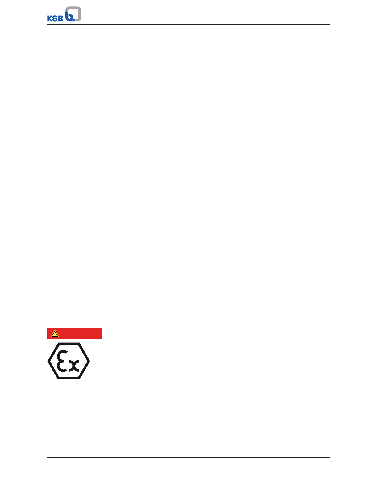
2.10 Explosion protection
!
DANGER
Always observe the information on explosion protection given in this section when
operating an explosion-proof pump set.
Sections of the manual marked by the symbol opposite apply to explosion-proof
pump sets also when temporarily operated outside of potentially explosive
atmospheres.
Only pumps/pump sets marked as explosion-proof and identified as such in the data
sheet may be used in potentially explosive atmospheres.
Special conditions apply to the operation of an explosion-proof pump set to
EUDirective 2014/34/EU (ATEX).
Especially adhere to the sections in this manual marked with the symbol opposite.
The explosion-proof status of the pump set is only assured if the pump set is used in
accordance with its intended use.
Never operate the pump set outside the limits stated in the data sheet and on the
name plate.
Prevent impermissible modes of operation.
Page 11

2 Safety
11 of 132
Amacan P
2.10.1 Repair
Special regulations apply to repair work on explosion-proof pumps. Modifications or
alterations of the pump set can affect explosion protection and are only permitted
after consultation with the manufacturer.
Repair work at the flameproof joints must only be performed in accordance with the
manufacturer's instructions. Repair to the values in tables 1 and 2 of EN60079-1 is
not permitted.
Page 12

3 Transport/Temporary Storage/Disposal
12 of 132
Amacan P
3 Transport/Temporary Storage/Disposal
3.1 Checking the condition upon delivery
1. On transfer of goods, check each packaging unit for damage.
2. In the event of in-transit damage, assess the exact damage, document it and
notify KSB or the supplying dealer and the insurer about the damage in writing
immediately.
3.2 Transport
DANGER
Improper transport
Danger to life from falling parts!
Damage to the pump set!
▷ Use the attachment point provided for attaching the lifting accessory.
▷ Never suspend the pump set by its power cable.
▷ Use the lifting chain/rope included in the scope of supply exclusively for
lowering or lifting the pump set into/out of the pump sump.
▷ Securely attach the lifting chain/rope to the pump and crane.
▷ Use tested, marked and approved lifting accessories only.
▷ Observe the regional transport regulations.
▷ Observe the product literature supplied by the lifting accessory manufacturer.
▷ The load-carrying capacity of the lifting accessory must be higher than the
weight indicated on the name plate of the pump set to be lifted. Take into
account any additional system components to be lifted.
3.2.1 Transporting the delivered pump to the place of installation
Fig.1: Transporting the pump set in its original packaging
▪ The pump set is supplied in a horizontal position on a suitable transport support.
▪ Use suitable lifting equipment to transport the pump set in its original packaging
to its place of installation.
Observe the marked centres of gravity and/or attachment points on the transport
boxes!
For the weight refer to the name plate or data sheet. (ðSection4.3,Page18)
3.2.2 Placing the pump set in a vertical or horizontal position
WARNING
Pump set tilting
Risk of squashing hands and feet!
▷ Suspend or support the pump set.
Page 13
3 Transport/Temporary Storage/Disposal
13 of 132
Amacan P
WARNING
Placing the pump set down on unsecured and uneven surfaces
Personal injury and damage to property!
▷ Always place down the pump set on a solid and level surface with the pump set
in a vertical position and the motor on top.
▷ Only place the pump set on a surface of sufficient load-carrying capacity.
▷ Use appropriate means to secure the pump set against tilting or tipping over.
▷ Refer to the weights given in the data sheet/on the name plate.
WARNING
Incorrect handling of the power cable
Personal injury and damage to property!
▷ Secure the power cables against falling down.
▷ Avoid power cables being laid on surfaces without fastening.
▷ When moving the pump set keep at a safe distance from the power cables.
WARNING
Improper handling when placing the pump set in a vertical/horizontal position
Personal injury and damage to property!
▷ Use one or two pieces of lifting equipment, depending on the pump size.
▷ Use appropriate means to secure the pump set against tilting, tipping over or
rolling off.
▷ Maintain a safe distance during lifting operations (load may swing when being
lifted).
▷ Use additional supports for the transport holder to secure it against tilting.
WARNING
Improper lifting/moving of heavy assemblies or components
Personal injury and damage to property!
▷ Use suitable transport devices, lifting equipment and lifting tackle to move
heavy assemblies or components.
CAUTION
Improper storage
Damage to the power cables!
▷ Support the power cables at the cable entry to prevent permanent
deformation.
▷ Only remove the protective caps from the power cables at the time of
installation.
Page 14
3 Transport/Temporary Storage/Disposal
14 of 132
Amacan P
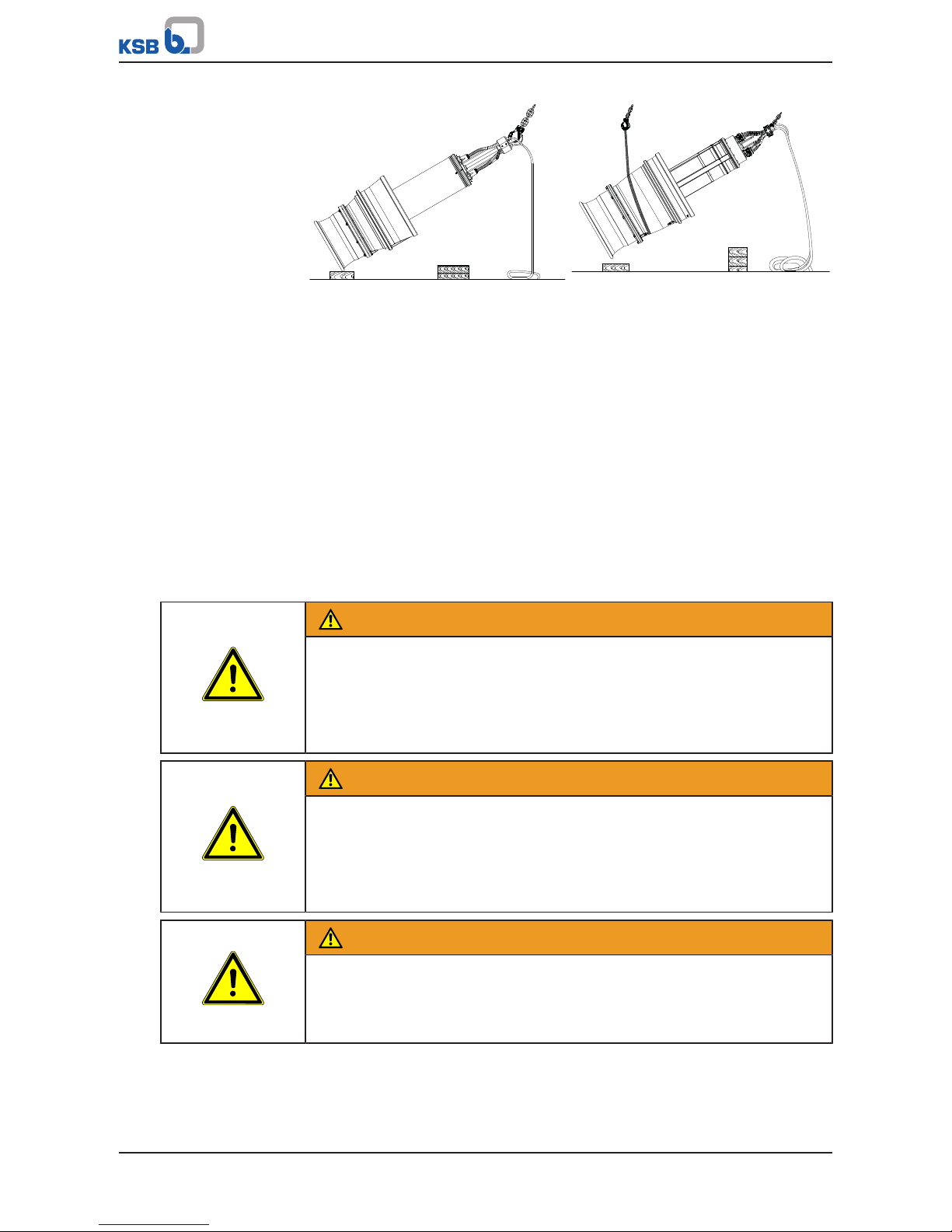
Pulling the pump set upright with one
crane
Pulling the pump set upright with two
cranes
ü Suitable lifting equipment has been selected (e.g. crane).
1. a) For one piece of lifting equipment: Attach the eyehook to the bail of the
pump set.
b) For two pieces of lifting equipment: Attach one eyehook to the bail of the
pump set. Then suitably loop a rope around the pump set and attach this loop
to the second crane hook.
2. Lift the pump set with the lifting equipment.
ð Guiding the pump set over the edge of the bellmouth or pump casing is only
permissible on a wooden base!
ð Protect the power cable against kinking!
3. Place the pump set on a level, clean surface and protect it against tilting, tipping
over or rolling off.
3.2.3 Transporting the pump set
WARNING
Incorrect positioning/placing down
Personal injury and damage to property!
▷ Position the pump set vertically with the motor on top.
▷ Use appropriate means to secure the pump set against tilting and tipping over.
▷ Refer to the weights given in the data sheet/on the name plate.
WARNING
Incorrect handling of the power cable
Personal injury and damage to property!
▷ Secure the power cables against falling down.
▷ Avoid power cables being laid on surfaces without fastening.
▷ When moving the pump set keep at a safe distance from the power cables.
WARNING
Improper lifting/moving of heavy assemblies or components
Personal injury and damage to property!
▷ Use suitable transport devices, lifting equipment and lifting tackle to move
heavy assemblies or components.
Page 15
3 Transport/Temporary Storage/Disposal
15 of 132
Amacan P
WARNING
Improper handling when placing the pump set in a vertical/horizontal position
Personal injury and damage to property!
▷ Use one or two pieces of lifting equipment, depending on the pump size.
▷ Use appropriate means to secure the pump set against tilting, tipping over or
rolling off.
▷ Maintain a safe distance during lifting operations (load may swing when being
lifted).
▷ Use additional supports for the transport holder to secure it against tilting.
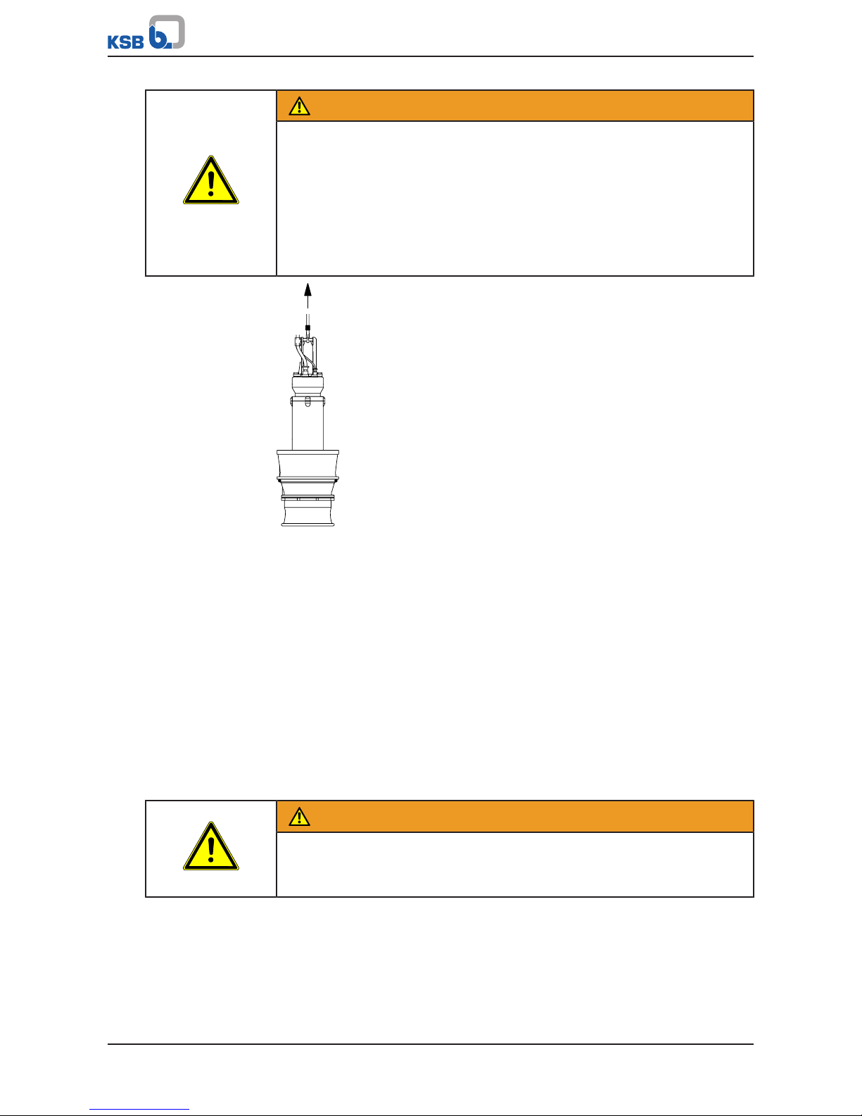
Fig.2: Transporting the pump set in a vertical position
Use suitable lifting equipment to transport the pump set in the illustrated position.
3.2.4 Transport lock
Pump sets from size Amacan P 1000 - 700 are supplied with a transport lock. Prior to
checking the direction of rotation, lowering the pump into the discharge tube and
commissioning, remove the transport lock, which is a metal plate between impeller
and bellmouth.
3.3 Storage/preservation
If commissioning is to take place some time after delivery, we recommend that the
following measures be taken:
Store the pump set as follows:
▪ In its original packaging: in a horizontal position
▪ Without packaging: in a vertical position with the motor on top
WARNING
Pump set tilting
Risk of squashing hands and feet!
▷ Suspend or support the pump set.
Page 16
3 Transport/Temporary Storage/Disposal
16 of 132
Amacan P
CAUTION
Improper storage
Damage to the power cables!
▷ Support the power cables at the cable entry to prevent permanent
deformation.
▷ Only remove the protective caps from the power cables at the time of
installation.
CAUTION
Damage during storage due to humidity, dirt or vermin
Corrosion/contamination of the pump (set)!
▷ For outdoor storage cover the pump (set) or the packaged pump (set) and
accessories with waterproof material.
CAUTION
Wet, contaminated or damaged openings and connections
Leakage or damage to the pump!
▷ Clean and cover pump openings and connections as required prior to putting
the pump into storage.
Table4: Ambient conditions for storage
Ambient condition Value
Relative humidity 5% to 85% (non-condensing)
Ambient temperature -20°C to +70°C
▪ Store the pump set under dry and vibration-free conditions, if possible in its
original packaging.
1. Rotate the impeller by hand once every three months.
3.4 Return to supplier
1. Drain the pump as per operating instructions. (ðSection7.3.2,Page54)
2. Flush and clean the pump, particularly if it has been used for handling noxious,
explosive, hot or other hazardous fluids.
3. If the pump has handled fluids whose residues could lead to corrosion damage
in the presence of atmospheric humidity or could ignite upon contact with
oxygen also neutralise the pump and blow through with anhydrous inert gas to
ensure drying.
4. Always complete and enclose a certificate of decontamination when returning
the pump.
Indicate any safety measures and decontamination measures taken.
(ðSection11,Page127)
NOTE
If required, a blank certificate of decontamination can be downloaded from the
following web site: www.ksb.com/certificate_of_decontamination
Page 17

3 Transport/Temporary Storage/Disposal
17 of 132
Amacan P
3.5 Disposal
WARNING
Fluids handled, consumables and supplies which are hot and/or pose a health
hazard
Hazard to persons and the environment!
▷ Collect and properly dispose of flushing fluid and any fluid residues.
▷ Wear safety clothing and a protective mask if required.
▷ Observe all legal regulations on the disposal of fluids posing a health hazard.
1. Dismantle the pump (set).
Collect greases and other lubricants during dismantling.
2. Separate and sort the pump materials, e.g. by:
- Metals
- Plastics
- Electronic waste
- Greases and other lubricants
3. Dispose of materials in accordance with local regulations or in another
controlled manner.
Page 18
4 Description of the Pump (Set)
18 of 132
Amacan P
4 Description of the Pump (Set)
4.1 General description
▪ Submersible pump in discharge tube
Pump set for handling river water and stormwater, pre-screened domestic and
industrial waste water as well as activated sludge
4.2 Designation
Example: Amacan PA4 800-540 / 120 6UTG1
Table5: Designation key
Code Description
Amacan Type series
P Impeller type
P Propeller
A Pressure class
A
B
4 Number of vanes
800 Nominal diameter of the discharge tube [mm]
540 Nominal impeller diameter [mm]
120 Motor size
6 Number of motor poles
UT Motor version
UT Without explosion protection, standard
XT
Explosion protection II 2G Ex db h IIB T3 Gb
G1 Material variant
G1 Grey cast iron, standard material variant
G3 Grey cast iron with Zn anodes, shaft made of 1.4057 stainless steel
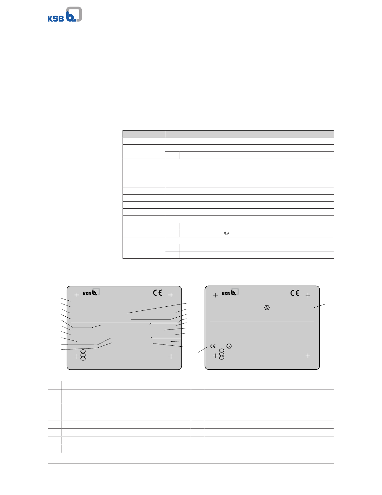
4.3 Name plate
a)
b)
TYPE
No.
Q
TEMP. MAX. °C kg
H
WARNING - DO NOT OPEN WHEN ENERGIZED
AVERTISSEMENT - NE PAS OUVRIR SOUS TENSION
MOTOR IP 68 SUBM. MAX. 30 m CLASS H
3 ~ M.-No.
V Hz cosφ
A IA/IN
kWP
2
WARNUNG - NICHT UNTER SPANNUNG ÖFFNEN
EN
DE
FR
min
-1
S1
5 m
40
1165
2018
970
149/86
4,7
0,87
400/690
50
123456
1
2
3
4
11
12
13
6
5
7
8
9
10
15
16
17
14
18
19
20
TYPE
No.
Q
TEMP. MAX. °C kg
H
WARNING - DO NOT OPEN WHEN ENERGIZED
AVERTISSEMENT - NE PAS OUVRIR SOUS TENSION
MOTOR IP 68 SUBM. MAX. 30 m CLASS H
3 ~ M.-No.
V Hz cosφ
A IA/IN
kWP
2
WARNUNG - NICHT UNTER SPANNUNG ÖFFNEN
EN
DE
FR
min
-1
S1
II 2G Ex db h IIB T3 Gb
0035 II 2G Ex db IIB T3 Gb
40
2018
21
9970918352/001010
4000 m3/h
80
R22L06-80
Amacan PA4 800-540/806 UTG1
Amacan PA4 800-540/806 XTG1
5 m
1165
970
149/86
4,7
0,87
400/690
50
123456
9970918352/001010
1600 m3/h
80
R22L06-80
22
IBExU08 ATEX 1064X
Johann-Klein-Straße 9
Deutschland
67227 Frankenthal
KSB SE & Co. KGaA
Johann-Klein-Straße 9
Deutschland
67227 Frankenthal
KSB SE & Co. KGaA
Fig.3: Name plate (example) a) Standard pump set b) Explosion-proof pump set
1 Designation 2 KSB order number
3 Flow rate 4 Maximum fluid temperature and ambient
temperature
5 Enclosure 6 Motor type
7 Rated power 8 Rated speed
9 Rated voltage 10 Rated current
11 Head 12 Year of construction
13 Total weight 14 Maximum submergence
15 Thermal class of winding insulation 16 Motor number
Page 19
4 Description of the Pump (Set)
19 of 132
Amacan P
17 Power factor at rated operating point 18 Rated frequency
19 Duty cycle 20 Starting current ratio
21 ATEX marking for the submersible motor 22 ATEX marking for the pump set
4.4 Design details
Design
▪ Fully floodable submersible pump in discharge tube (submersible motor pump)
▪ Not self-priming
▪ Close-coupled design
▪ Single-stage
▪ Vertical installation
Drive
▪ Three-phase asynchronous squirrel-cage motor
▪ Type of protection Ex db IIB (motor integrated in explosion-proof pump set)
▪ Enclosure: IP68 to EN60529/IEC529
Shaft seal
▪ Two bi-directional mechanical seals in tandem arrangement, with liquid reservoir
▪ Leakage chamber
Impeller type
▪ Axial propeller in ECB design
Bearings
▪ Grease-lubricated rolling element bearings
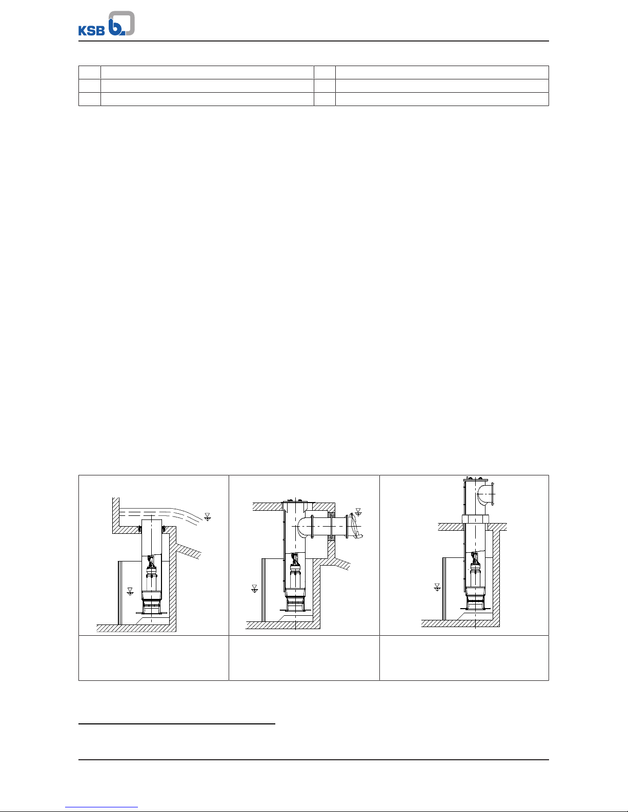
4.5 Installation types
Six different types are available for selection2):
Table6: Overview of installation types
BU discharge tube
Overflow design for installation in
open intake chamber
CU discharge tube
Design with underfloor discharge
for installation in open intake
chamber
DU discharge tube
Design with above floor discharge
nozzle for installation in open intake
chamber
2) For information on the various designs (foundation measurements, intake chamber, etc.) refer to the general arrangement
drawings.
Page 20
4 Description of the Pump (Set)
20 of 132
Amacan P
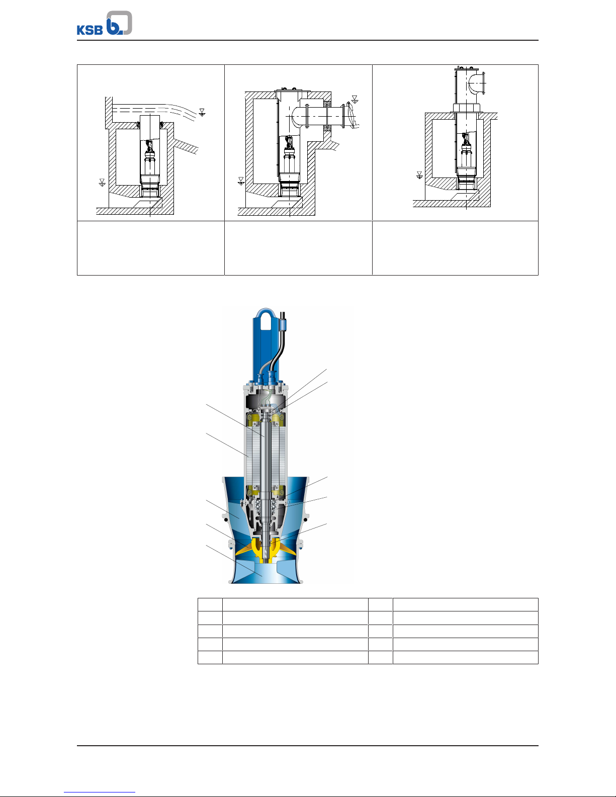
BG discharge tube
Overflow design for installation in
covered intake chamber with low
suction-side water levels
CG discharge tube
Design with underfloor discharge
for installation in covered intake
chamber with low suction-side
water levels
DG discharge tube
Design with above-floor discharge
nozzle for installation in covered intake
chamber with low suction-side water
levels
4.6 Configuration and function
1
2
3
4
5
6
7
8
9
10
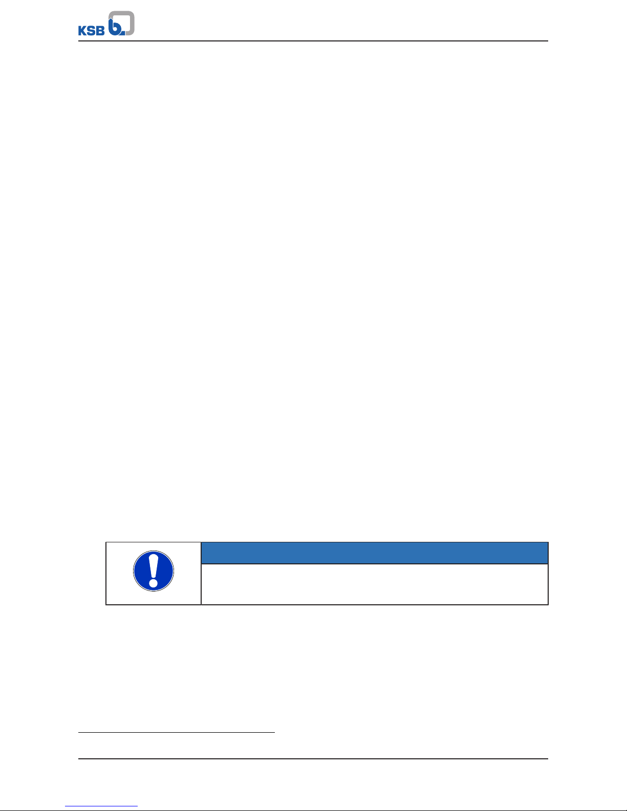
Fig.4: Amacan with axial propeller
1 Suction nozzle (bellmouth) 2 Impeller
3 Pump bowl 4 Electric motor
5 Shaft 6 Bearing, motor end
7 Bearing bracket 8 Bearing, pump end
9 Bearing housing, pump end 10 Shaft seal
Design The pump is designed with an axial fluid inlet and an axial outlet. The hydraulic
system sits on the extended motor shaft. The shaft runs in common bearings.
Function The fluid enters the pump axially via a suction nozzle (bellmouth) (1) and is
accelerated outward in a rotating flow by the rotating impeller (2). The required
energy is transmitted from the electric motor (4) to the impeller (2) via the shaft (5).
In the pump bowl (3) the kinetic energy of the fluid is converted into pressure energy
Page 21
4 Description of the Pump (Set)
21 of 132
Amacan P
and the rotational movement of the fluid flow is diverted in axial direction. The shaft
passage through the casing is sealed towards the fluid with a shaft seal (10). The
shaft (5) runs in two rolling element bearings (6 and 8), which are supported by the
bearing housing (9) and the bearing bracket (7).
Sealing The pump is sealed by two bi-directional mechanical seals in tandem arrangement.
A lubricant reservoir in-between the seals ensures cooling and lubrication of the
mechanical seals.
Monitoring
equipment
The pump sets are equipped with various sensors.
Standard
▪ Temperature monitoring of the motor
▪ Temperature monitoring at the lower bearing
▪ Leakage monitoring of mechanical seals
▪ Leakage sensors in the motor chamber and connection space
Option
▪ Temperature monitoring at the upper bearing
3)
▪ Vibration sensor
▪ Additional winding temperature monitoring with Pt100 resistance thermometer
4.7 Scope of supply
Depending on the model, the following items are included in the scope of supply:
▪ Pump set complete with power cables
▪ O-ring
▪ Back-up name plate
Optional accessories:
▪ Support rope
▪ Accessories for installing the cable guide:
– Fitting
– Turnbuckle
– Support
– Shackle
– Cable clamps
▪ Cable support sleeves
▪ Discharge tube
▪ Flow-straightening vane to prevent floor vortices
NOTE
A separate name plate is included in KSB's scope of supply.
This name plate must be attached in a clearly visible position outside the place of
installation, e.g. at the control panel, pipeline or mounting bracket.
4.8 Dimensions and weights
For dimensions and weights refer to the name plate or data sheet of the pump set.
3) Included in the standard design for size 1600-1060
Page 22
5 Installation at Site
22 of 132
Amacan P
5 Installation at Site
5.1 Safety regulations
DANGER
Improper installation in potentially explosive atmospheres
Explosion hazard!
Damage to the pump set!
▷ Comply with the applicable local explosion protection regulations.
▷ Observe the information in the data sheet and on the name plates of pump and
motor.
DANGER
Persons in the intake chamber during pump set operation
Electric shock! Risk of injury!
▷ Never start up the pump set when there are persons in the intake chamber.
WARNING
Impermissible solid objects (tools, screws/bolts or similar) in the pump sump/inlet
tank during pump start-up
Personal injury and damage to property!
▷ Check the pump sump/inlet tank for impermissible solid objects before
flooding, and remove, if necessary.
5.2 Checks to be carried out prior to installation
5.2.1 Checking the structural requirements
All structural work required must have been prepared in accordance with the
dimensions stated in the outline drawing/general arrangement drawing.
5.2.2 Checking the operating data
Before inserting the pump set into the discharge tube, verify the data on the name
plate against the data given in the purchase order and the system data.
Back-up name plate KSB’s scope of supply includes a separate name plate attached to the end of the
pump cable which indicates the pump and motor data.
1. Attach this name plate in a clearly visible position outside the discharge tube,
e.g. at the control cabinet, pipeline or mounting bracket.
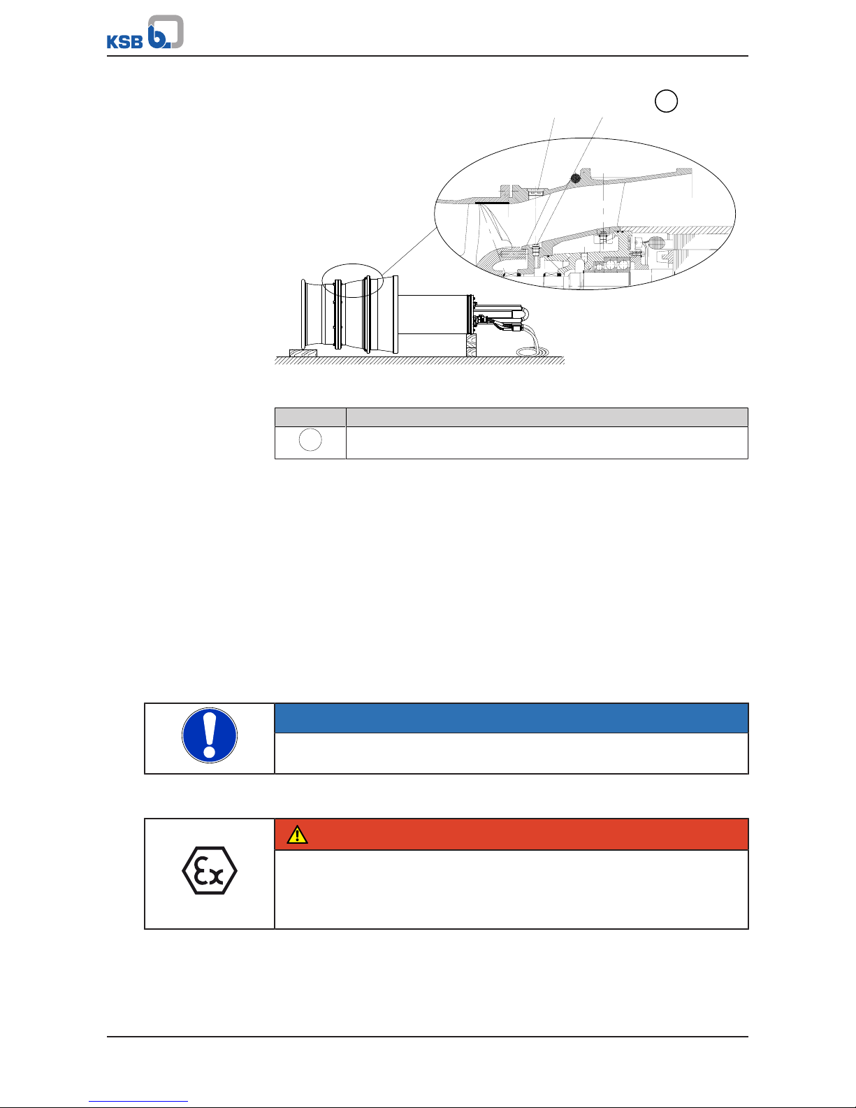
5.2.3 Checking the lubricant of the mechanical seal
The lubricant reservoir is filled at the factory with an environmentally-friendly, nontoxic lubricant.
The pump set is supplied in a horizontal position on a suitable transport support.
Visual inspection for signs
of oil leakage
1. If no oil leakage is visible in the area of pump bowl, impeller or transport
support, the lubricant reservoir is filled properly.
2. If oil leakage is visible in the area of pump bowl, impeller or transport support,
top up the lubricant.
Page 23
5 Installation at Site
23 of 132
Amacan P
903.03
903.01
411.01
FD
Fig.5: Checking the lubricant level
Table7: Key to the symbols and codes
Symbol Description
FD
Always apply a liquid sealant (e.g. Hylomar SQ32M) to sealing surfaces
marked with this symbol.
1. Place the pump set down in a horizontal position and make sure it cannot roll
off. (ðSection3.2.2,Page12)
2. When placing the pump set down, make sure that screw plug 903.03 is on top.
3. Remove screw plug 903.03.
4. Remove screw plug 903.01 and joint ring 411.01.
5. Shine a torch through the hole in the pump bowl to see the opening of the
lubricant reservoir.
ð If the lubricant level reaches the opening, fit screw plug 903.01 together with
a new joint ring 411.01, and screw plug 903.03.
ð If the lubricant level is below the opening, top up the lubricant.
(ðSection7.4.1.4.2,Page58)
6. Re-insert and tighten screw plug 903.01 with joint ring.
7. Re-insert and tighten screw plug 903.03.
NOTE
If more than 1.5 litres of lubricant are required for topping up, this suggests a
defect of the mechanical seals.
5.2.4 Checking the direction of rotation
DANGER
Pump set running dry
Explosion hazard!
▷ Check the direction of rotation of explosion-proof pump sets outside
potentially explosive atmospheres.
Page 24
5 Installation at Site
24 of 132
Amacan P
WARNING
Improper handling when placing the pump set in a vertical/horizontal position
Personal injury and damage to property!
▷ Use one or two pieces of lifting equipment, depending on the pump size.
▷ Use appropriate means to secure the pump set against tilting, tipping over or
rolling off.
▷ Maintain a safe distance during lifting operations (load may swing when being
lifted).
▷ Use additional supports for the transport holder to secure it against tilting.
WARNING
Improper positioning of pump set when checking the direction of rotation
Personal injury and damage to property!
▷ Use appropriate means to secure the pump set against tilting or tipping over.
WARNING
Hands and/or foreign objects in the pump casing
Risk of injuries, damage to the pump!
▷ Never insert your hands or any other objects into the pump.
▷ Check that the inside of the pump is free from any foreign objects.
▷ Verify that the transport lock has been removed.
▷ Take suitable precautions (e.g. wear safety goggles).
CAUTION
Pump set running dry
Increased vibrations!
Damage to mechanical seals and bearings!
▷ Never operate the pump set for more than 60seconds outside the fluid to be
handled.
Check the direction of rotation before installing the pump set, i.e. in dry condition.
1. Place the pump set in a vertical position on a level surface and secure it
sufficiently against tipping over. (ðSection3.2.2,Page12)
2. Connect the pump set to the power supply and start it up.
3. Use one of the following options to check the direction of rotation:
ð 1. Look down into the pump bowl and check that the impeller is turning
clockwise.
ð 2. Verify the direction of rotation of the impeller against the arrow
indicating the direction of rotation on the pump bowl.
4. If the impeller rotates in the wrong direction of rotation, check and correct the
electrical connection and the control system if applicable. Then check the
direction of rotation again.
5. If the direction of rotation is correct, mark which core ends match which of the
terminals in the control cabinet.
6. Disconnect the pump set from the power supply and secure it against
unintentional start-up.
Page 25
5 Installation at Site
25 of 132
Amacan P
WARNING
Unintentional starting of the pump set
Risk of injury by moving components and shock currents!
▷ Ensure that the pump set cannot be started unintentionally.
▷ Always make sure the electrical connections are disconnected before carrying
out work on the pump set.
5.3 Lowering the pump set into the discharge tube
DANGER
Improper transport
Danger to life from falling parts!
Damage to the pump set!
▷ Use the attachment point provided for attaching the lifting accessory.
▷ Never suspend the pump set by its power cable.
▷ Use the lifting chain/rope included in the scope of supply exclusively for
lowering or lifting the pump set into/out of the pump sump.
▷ Securely attach the lifting chain/rope to the pump and crane.
▷ Use tested, marked and approved lifting accessories only.
▷ Observe the regional transport regulations.
▷ Observe the product literature supplied by the lifting accessory manufacturer.
▷ The load-carrying capacity of the lifting accessory must be higher than the
weight indicated on the name plate of the pump set to be lifted. Take into
account any additional system components to be lifted.
DANGER
Improper installation in potentially explosive atmospheres
Explosion hazard!
Damage to the pump set!
▷ Comply with the applicable local explosion protection regulations.
▷ Observe the information in the data sheet and on the name plates of pump and
motor.
WARNING
Incorrect handling of the power cable
Personal injury and damage to property!
▷ Secure the power cables against falling down.
▷ Avoid power cables being laid on surfaces without fastening.
▷ When moving the pump set keep at a safe distance from the power cables.
WARNING
People falling into the unsecured discharge tube
Risk of personal injury!
▷ Take suitable precautions during the entire installation/removal process to
protect people from falling into the open discharge tube.
▷ Fence off the work area appropriately.
Page 26

5 Installation at Site
26 of 132
Amacan P
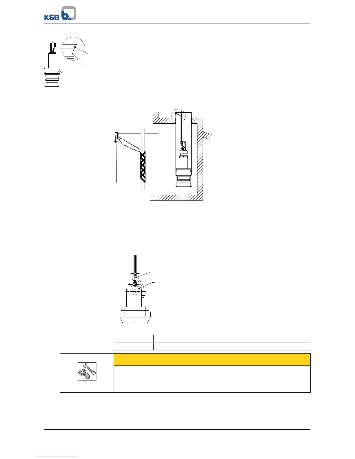
5.3.1 Information for correct installation
The flow-straightening vane is indispensable for the inlet conditions of the pump
set. It prevents the development of a submerged vortex (floor vortex) which could
cause a drop in performance, for example. To provide optimum inlet conditions,
observe the following information:
1. Observe the structural requirements!
Install the flow-straightening vane concentrically below the discharge tube, see
general arrangement drawing.
1
2
3
Fig.6: Installation position of the flow-straightening vane
1 Flow-straightening vane 2 Discharge tube
3 Intake chamber
2. Observe the installation position of the pump set!
Lower the pump set into the discharge tube with the anti-swirl baffles (2) in the
bellmouth aligned with the flow-straightening vane (3).
Use the bail alignment of the pump set for orientation. The bail (1) is aligned
with the anti-swirl baffles (2).
1
2
3
Fig.7: Installation position of the pump set
1 Bail 2 Anti-swirl baffles
3 Flow-straightening vane
5.3.2 Installation without support rope
CAUTION
Incorrect installation
Damage to the pump set!
▷ Verify that the pump set is correctly seated in the discharge tube.
Page 27
5 Installation at Site
27 of 132
Amacan P
412.05
112
Fig.8: Inserting the O-ring
Refer to and comply with the general arrangement drawing/outline drawing when
installing the pump set.
1. If not already fitted, insert the supplied O-ring 412.05 into pump bowl 112.
2. Attach the crane hook to the bail of the pump set.
3. Centre the pump set above the discharge tube. Slowly lower the pump set into
the discharge tube until it is seated in the recommended position.
(ðSection5.3.1,Page26)
4. Pull the electric cables up by hand. Fasten them to the sump construction with a
cable support sleeve if required. Do not lift the pump set out of its seat.
X
X
Fig.9: Fastening the cable support sleeve
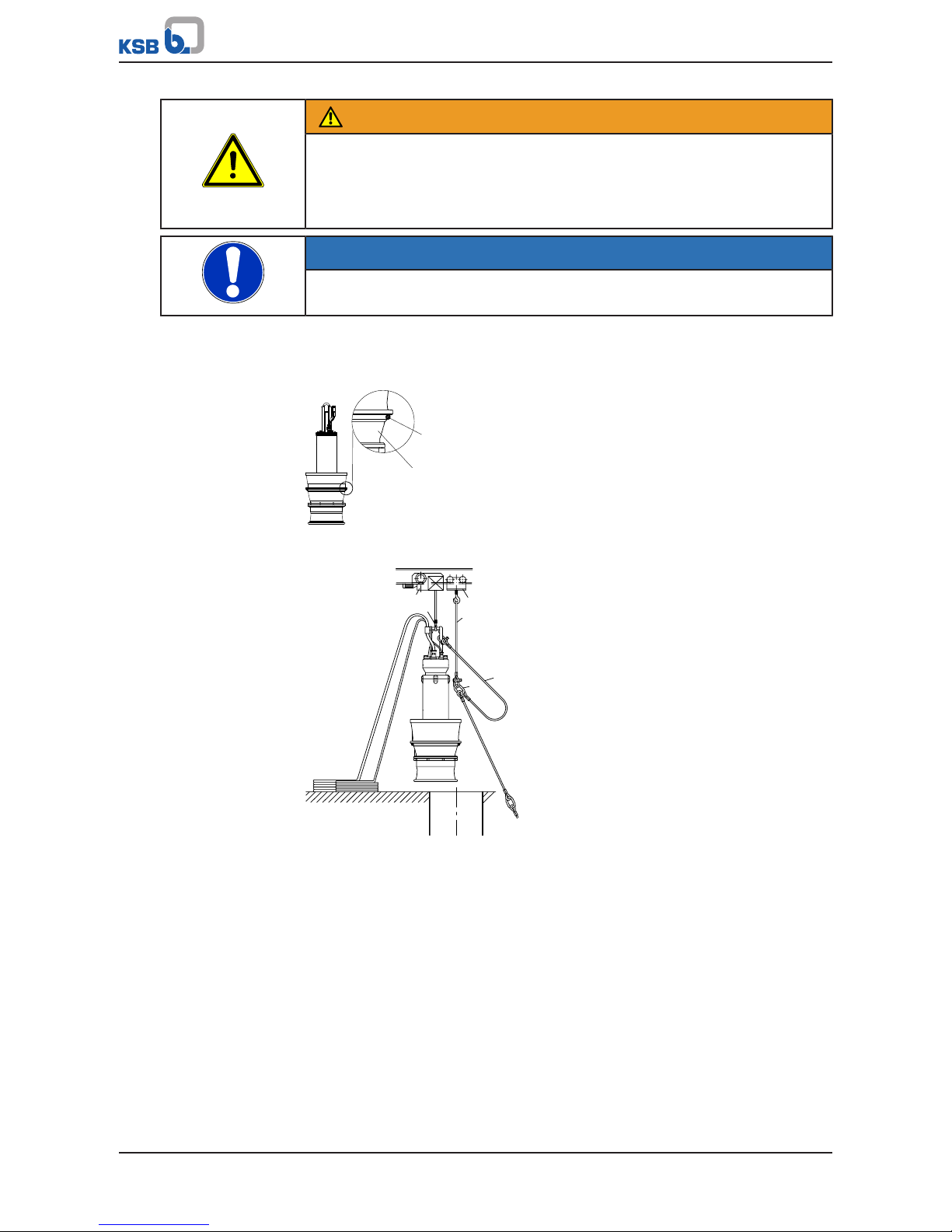
5.3.3 Installation with a support rope
Refer to and comply with the general arrangement drawing/outline drawing when
installing the pump set.
Prior to installing the pump set, visually inspect the support rope. Do not exceed the
permissible load-carrying capacity.
X
59-24
X
59-17.01
Fig.10: X = indication of load-carrying capacity
59-24 Support rope
59-17.01 Shackle
CAUTION
Incorrect installation
Damage to the pump set!
▷ Verify that the pump set is correctly seated in the discharge tube.
Page 28
5 Installation at Site
28 of 132
Amacan P
WARNING
Pump set drops during the installation or removal process
Personal injury and damage to property!
▷ Never use the turnbuckle , shackle or discharge tube cover to lift the pump set.
▷ Always use lifting lug 59-47.
NOTE
Prior to fitting the turnbuckle, check that the corresponding split pin has not been
cracked and/or chipped. If damaged, always use a new split pin.
ü Suitably sized lifting equipment is available.
ü The support rope has been visually inspected.
ü The split pin of the turnbuckle has been checked for any damage.
412.05
112
Fig.11: Inserting the O-ring
1. If not already fitted, insert the supplied O-ring 412.05 into pump bowl 112.
1
2
3
4
5
6
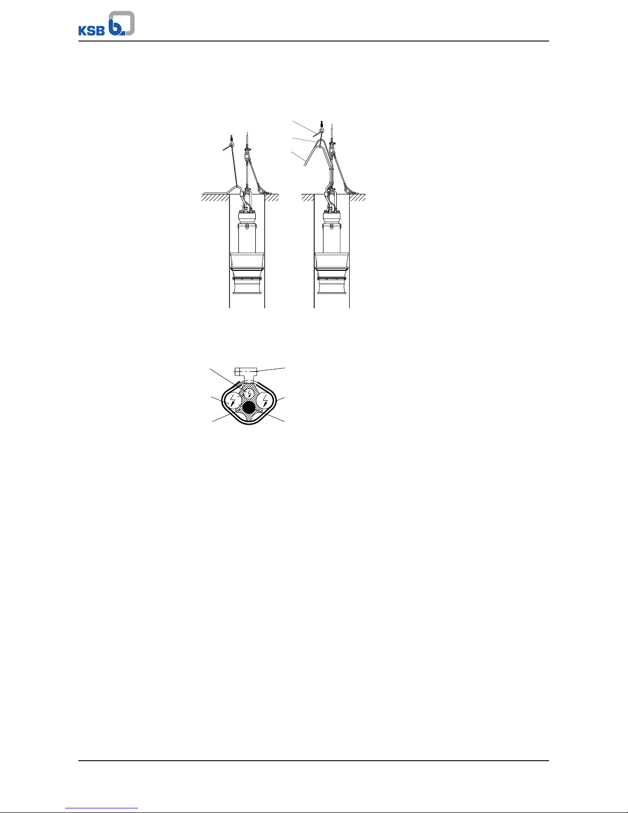
Fig.12: Lifting and positioning the pump set
2. Secure the lifting chain or lifting rope (1) to the trolley (4) of the lifting
equipment (2).
3. Attach the support rope (5) to the bail by its shackle. (ðSection9.2,Page94)
For a galvanised shackle, secure the pin at the shackle with Loctite243.
For a stainless steel shackle, undo and tighten the pin twice and secure it with
Loctite243.
4. Check that the support rope is arranged correctly.
ð The free lifting lug (6) has to point away from the pump set
5. Partially unwind the support rope and electric cables.
6. Lower the pump set into the discharge tube until the bail is in an accessible
position, protruding from the discharge tube.
7. Securely cover the discharge tube except for a gap which allows work to
continue.
Page 29
5 Installation at Site
29 of 132
Amacan P
8. Attach the first lifting lug of the support rope (5) to the lifting rope (1) to
securely position the pump set above the discharge tube.
9. Unclip the hook of the lifting equipment from the lifting lug of the support
rope and run the lifting equipment to a higher level.
8
7
9
Fig.13: Securing the control cable and power cable
10. Secure the control cable (7) and power cables (8) to the crane hook (3) of the
lifting equipment with a manila rope (9).
11. Trim spacer (a) to fit between the two ferrules.
a
b
c
d
e
f
Fig.14: Cross-section of the cable guide
12. Insert the support rope (f) and the control cable (c) into the spacer (a) and make
sure that they are in their respective ducts.
13. Tighten the electric cables with the manila rope running over the crane hook.
14. Insert the power cables (b) into the hollows of the spacer (a) and, starting from
the bottom, firmly clamp the power cables with cable clamps (d) covered by a
plastic sheath (e).
15. In the area of the lifting lug between the rope sections, lay all electric cables in
loops and fasten them to the rope section above.
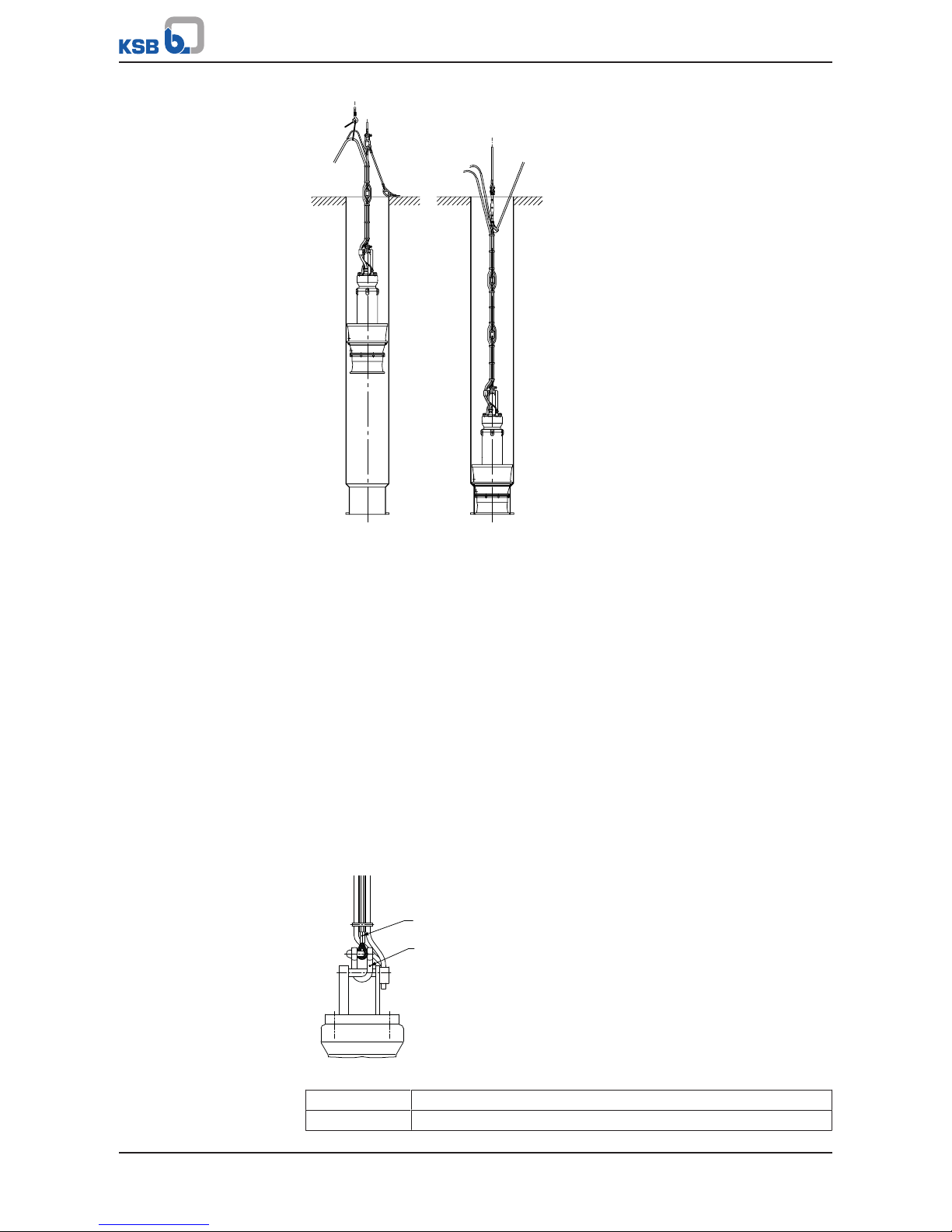
16. Progressively lower the pump set into the discharge tube while securing the
cable bundle with evenly spaced sheathed cable clamps.
17. Fit a heat shrink tube on any protruding sharp-edged rope ends (e.g. at the
ferrule) to prevent any damage to the power cable and control cable.
Page 30
5 Installation at Site
30 of 132
Amacan P
Fig.15: Lowering the pump set
18. Finally, attach the support rope with shackle and turnbuckle to a suspension
loop (provided in the discharge tube or structure). Secure the turnbuckle with a
split pin. After inserting the split pin, bend over its two legs.
19. Tighten the turnbuckle until the cable bundle is tight without lifting the pump
off its seat.
20. Unclip the hook of the lifting equipment from the lifting lug, free the electric
cables from the manila rope and route them to the control cabinet.
21. Make sure that the top loose lifting lug is attached to the cable bundle to
prevent noise and wear caused by chafing.
22. Remove the safety cover from the discharge tube and mount the discharge tube
cover. Seal the cable entries if any!
5.3.4 Installation with a support rope and support spacer
Always refer to and comply with the general arrangement drawing/ outline drawing
when installing the pump set.
Prior to installing the pump set, visually inspect the support rope. Do not exceed the
permissible load-carrying capacity.
X
59-24
X
59-17.01
Fig.16: X = indication of load-carrying capacity
59-24 Support rope
59-17.01 Shackle
Page 31

5 Installation at Site
31 of 132
Amacan P
CAUTION
Incorrect installation
Damage to the pump set!
▷ Verify that the pump set is correctly seated in the discharge tube.
WARNING
Pump set drops during the installation or removal process
Personal injury and damage to property!
▷ Never use the turnbuckle , shackle or discharge tube cover to lift the pump set.
▷ Always use lifting lug 59-47.
NOTE
Prior to fitting the turnbuckle, check that the corresponding split pin has not been
cracked or chipped. If damaged, always use a new split pin.
ü Suitably sized lifting equipment is available.
ü The support has been supplied pre-assembled and is available for use.
ü The support rope has been visually inspected.
ü The split pin of the turnbuckle has been checked for any damage.
412.05
112
Fig.17: Inserting the O-ring
1. If not already fitted, insert the supplied O-ring 412.05 into pump bowl 112.
1
2
3
4
5
6
Fig.18: Lifting and positioning the pump set
2. Secure the lifting chain or rope (1) to the trolley (4) of the lifting equipment (2).
3. Attach the support rope (5) to the bail by its shackle. Check that the support
rope is arranged with the free lifting lug (6) pointing away from the pump set.
4. Partially unwind the support rope and cables.
5. Lower the pump set into the discharge tube until the bail is in an accessible
position, protruding from the discharge tube.
Page 32

5 Installation at Site
32 of 132
Amacan P
6. Securely cover the discharge tube except for a gap which allows work to
continue.
7. Attach the first lifting lug of the support rope (5) to the lifting rope (1) to
securely position the pump set above the discharge tube.
8. Unclip the hook of the lifting equipment from the lifting lug of the support
rope and run the lifting equipment to a higher level.
8
7
9
Fig.19: Securing the control and power cables
9. Secure the control cable (7) and power cables (8) to the crane hook (3) of the
lifting equipment with a manila rope (9).
10. Trim the spacer (a) to fit between the two ferrules.
a
b
c
d
e
f
Fig.20: Cross-section of the cable guide
11. Insert the support rope (f) and the control cable (c) into the spacer (a) and make
sure that they are in their respective ducts.
12. Tighten the cables with the manila rope running over the crane hook.
13. Insert the power cables (b) into the hollows of the spacer (a) and, starting from
the bottom, firmly clamp the power cables with cable clamps (d) covered by a
plastic sheath (e).
14. Progressively lower the pump set into the discharge tube while securing the
cable bundle with evenly spaced sheathed cable clamps.
15. In the area of the lifting lug between the rope sections, lay all cables in loops
and fasten them to the rope section above.
16. Fit a heat shrink tube on any protruding sharp-edged rope ends (e.g. at the
ferrule) to prevent any damage to the power and control cables.
17. Trim the spacer (a) to suit the position of support 59-7 at the support rope (f)
and the type of installation. Insert the support rope and control cable (c).
18. Insert the power cables (b) into the hollows of the spacer (a) and firmly clamp
the power cables with cable clamps (d).
Page 33

5 Installation at Site
33 of 132
Amacan P
59-7
X
X
733.05
719.05
901
920
550
733.05
719.05
59-24
81-51
(185, 81-39)
350 - 450 *)
50 **)
30
L
243
Fig.21: Support rope with support, dimensions in mm
*) depending on the cable cross-section,
**) for 1 rope or 3 ropes = 30mm
19. Clamp support 59-7 with guide plate 55-1 to the support rope (f).
20. Undo the screwed connection at the guide plate. Place clamp 81-39 of the guide
plate around the support rope.
21. Fasten plate 185 of the guide plate including the rod made of glass fibre
reinforced plastics to the clamp with hexagon head bolts 901, discs 550 and cap
nuts 920. Tighten the connection and secure it with Loctite243.
(ðSection9.2,Page94)
NOTE
The support must be clamped firmly to the support rope. If necessary, pad out
clamp 81-39.
22. Trim the spacer to fill the space between the two ferrules and accommodate the
support.
23. Guide the power and control cables along the support to the next cable clamp.
Pull them taught and secure them with the clamp.
Page 34

5 Installation at Site
34 of 132
Amacan P
Fig.22: Lowering the pump set
24. Progressively lower the pump set into the discharge tube. Secure the cables with
cable clamps.
25. Finally, attach the support rope with shackle and turnbuckle to a suspension
loop (provided in the discharge tube or structure). Secure the turnbuckle with a
split pin. After inserting the split pin, bend over its two legs.
26. Tighten the turnbuckle until the cable bundle is tight but does not lift the pump
off its seat.
27. Unclip the hook of the lifting equipment from the lifting lug, free the cables
from the manila rope and route them to the control cabinet.
28. Make sure that the top loose lifting lug is attached to the cable bundle to
prevent noise and wear caused by chafing.
29. Remove the safety cover from the discharge tube and mount the discharge tube
cover. Seal the cable entries if any.
Page 35
5 Installation at Site
35 of 132
Amacan P
5.4 Electrical system
5.4.1 Information for planning the control system
For the electrical connection of the pump set observe the wiring diagrams contained
in the Annex. (ðSection9.3,Page96)
The pump set is supplied with power cables; it is wired for DOL starting. Star-delta
starting is also possible, except for size Amacan P 1600-1060.
NOTE
When laying a cable between the control system and the pump set's connection
point, verify that the number of cores is sufficient for the sensors. A minimum crosssection of 1.5 mm² is required.
The motors can be connected to electrical low-voltage grids with mains voltages and
voltage tolerances to IEC60038. The permissible tolerances must be observed.
(ðSection6.2.1,Page44)
5.4.1.1 Starting method
The pump set is wired for DOL starting. Star-delta starting is technically possible.
For reducing the starting current autotransformers or soft starters can be used. For
selecting suitable devices observe the rated current of the motor.
At least three times the rated current is required for reliable start-up. The run-up
time must not exceed 4seconds.
After start-up of the pump, a soft starter must always be bypassed.
5.4.1.2 Overload protection
1. Protect the pump set against overloading by a thermal time-lag overload
protection device in accordance with IEC60947 and local regulations.
2. Set the overload protection device to the rated current specified on the name
plate. (ðSection4.3,Page18)
5.4.1.3 Level control
DANGER
Pump set running dry
Explosion hazard!
▷ Never allow an explosion-proof pump set to run dry!
CAUTION
Fluid level below the specified minimum
Damage to the pump set by cavitation!
▷ Never allow the fluid level to drop below the specified minimum.
Automatic operation of the pump set in a tank requires the use of level control
equipment.
Observe the minimum fluid level. (ðSection6.2.4.3,Page46)
5.4.1.4 Operation on a frequency inverter
The pump set is suitable for operation on a frequency inverter as per IEC60034-17.
Page 36

5 Installation at Site
36 of 132
Amacan P
NOTE
For pump sets with rated voltages exceeding 500V, a dv/dt filter should be fitted at
the output of the frequency inverter to reduce the rate of voltage rise to the limits
specified in IEC60034-17. Otherwise a considerably reduced service life of the
insulation system has to be expected.
DANGER
Operation outside the permitted frequency range
Explosion hazard!
▷ Never operate an explosion-proof pump set outside the specified range.
DANGER
Incorrect selection and setting of the frequency inverter
Explosion hazard!
▷ Observe the following information on selecting and setting a frequency
inverter.
Selection When selecting a frequency inverter, check the following details:
▪ Data provided by the manufacturer
▪ Electrical data of the pump set, particularly the rated current
▪ Only voltage source inverters (VSI) with pulse width modulation (PWM) and
carrier frequencies between 1 and 16kHz are suitable.
Setting Observe the following instructions for setting a frequency inverter:
▪ Set the current limit to max. 1.2 times the rated current. The rated current is
indicated on the name plate.
Start-up Observe the following instructions for starting the frequency inverter:
▪ Ensure short start ramps (maximum 5 seconds).
▪ Only start variable speed control after 2minutes at the earliest.
Pump start-up with long start ramps and low frequency may cause clogging.
Operation Observe the following limits during operation on a frequency inverter:
▪ Only utilise up to 95% of the motor rating P2 indicated on the name plate.
▪ Frequency range 25 to 50Hz
Electromagnetic
compatibility
Operation on a frequency inverter produces interference emissions whose level varies
depending on the inverter used (type, interference suppression, make). To prevent
the drive system, consisting of a submersible motor and a frequency inverter, from
exceeding any given limits always observe the EMC information provided by the
inverter manufacturer. If the inverter manufacturer recommends a shielded power
cable, make sure to use a submersible motor pump with shielded power cables.
Interference immunity The submersible motor pump generally meets interference immunity requirements.
For monitoring the sensors installed the operator must ensure sufficient interference
immunity by appropriately selecting and laying the power cables in the plant. No
modifications are required on the power/control cable of the submersible motor
pump. Suitable analysing devices must be selected. To monitor the leakage sensor
inside the motor using a special relay available from KSB is recommended.
Page 37

5 Installation at Site
37 of 132
Amacan P
5.4.1.5 Sensors
DANGER
Operating an incompletely connected pump set
Explosion hazard!
Damage to the pump set!
▷ Never start up a pump set with incompletely connected power connection
cables or non-operational monitoring devices.
CAUTION
Incorrect wiring
Damage to the sensors!
▷ Observe the limits stated in the following sections of this manual when
connecting the sensors.
The pump set features sensors designed to prevent hazards and damage to the pump
set.
Measuring transducers are required for analysing the sensor signals supplied. Suitable
devices for 230VAC can be supplied by KSB.
NOTE
Reliable and safe operation of the pump within the scope of our warranty is only
possible if the sensor signals are properly analysed as stipulated in this manual.
All sensors are located inside the pump set and are connected to the power cable.
For information on wiring and core identification please refer to the "Wiring
diagrams" section.
The individual sensors and the limit values to be set are described in the following
sections.
1
2
3
4
5
6
7
1
Fig.23: Sensor positions
Page 38

5 Installation at Site
38 of 132
Amacan P
Position Sensor Standard Optional
1 Leakage inside the motor (connection and winding
space)
✘ -
2 Bearing temperature (upper bearing) - ✘
3 Bearing temperature (lower bearings) ✘ 4 Mechanical seal leakage ✘ 5 Vibration sensor - ✘
6 Motor temperature (PTC) ✘ 7 Motor temperature (Pt100) - ✘
5.4.1.5.1 Motor temperature
DANGER
Insufficient cooling conditions
Explosion hazard!
Winding damage!
▷ Never operate a pump set without operational temperature monitoring.
▷ For explosion-proof pump sets use a thermistor tripping unit with manual reset
and ATEX approval for monitoring the temperature of explosion-proof motors
in "flameproof enclosure" Exd type of protection.
Three series-connected PTC thermistors at terminals 10 and 11 monitor the winding
temperature. Use a thermistor tripping unit with manual reset. For explosion-proof
pump sets use a thermistor tripping unit with manual reset which is ATEX-approved
for monitoring the temperature of explosion-proof motors in "flameproof
enclosure" Exd type of protection.
Pt100 resistance thermometer
As an option, in addition to the above, the motor can be fitted with Pt100 resistance
thermometers in the winding. These can be used to display the motor temperature
(sensor circuit maximum 6V/2mA).
CAUTION
Temperature monitoring devices not properly connected
Winding damage!
▷ Never use the resistance thermometers as the only means of monitoring the
motor temperature.
Page 39

5 Installation at Site
39 of 132
Amacan P
5.4.1.5.2 Leakage inside the motor
DANGER
Incorrect monitoring of leakage electrode
Explosion hazard!
Danger of death from electric shock!
▷ Voltages must be <30VAC and tripping currents <0.5mA.
PE
K 1
9
K 1
9
8
Wiring of the electrode relay
(standard)
Wiring of the electrode relay (pump
sets with vibration sensor only)
Position of the electrodes in the
motor housing
Electrodes fitted inside the motor monitor the winding and connection space for
leakage. Both electrodes are connected in parallel (core identification 9). They must
be connected to an electrode relay. Tripping of the electrode relay must result in the
pump set cutting out.
The electrode relay (K1) must fulfil the following requirements:
▪ Sensor circuit 10 to 30VAC
▪ Tripping current ≤0.5mA
Pump sets with vibration
sensors
A different wiring system is used for the electrodes of pump sets with vibration
sensors.
5.4.1.5.3 Mechanical seal leakage
Fig.24: Float switch
The chamber for mechanical seal leakage is equipped with a float switch (core
identification 3 and 4). The contact (maximum 250 V~/2 A) opens when leakage is
detected in the leakage chamber. Opening of the contact shall trigger an alarm
signal.
5.4.1.5.4 Bearing temperature
The lower bearing of the pump set is equipped with a bearing temperature sensor.
The sensor is a Pt100 resistance thermometer (core markings 15 and 16). It must be
connected to a temperature control device with a Pt100 input and 2 separate outputs
for two different switching points (sensor circuit maximum 6 V / 2 mA).
Set the following limits:
▪ Alert at 130 °C
▪ Cut-out of the pump set at 150 °C
Page 40

5 Installation at Site
40 of 132
Amacan P
As an option, the upper bearing can also be equipped with a temperature sensor
(core identification 16 and 17). Its connection and settings are identical with the
above. Check in the data sheet whether the pump set is equipped with temperature
monitoring of the upper bearing.
5.4.1.5.5 Vibration sensor
As an option, the pump set can be supplied with a vibration sensor in the area of the
upper bearing.
The vibration sensor measures the root-mean-square value of the radial vibration
velocity at the upper bearing. The sensor has an integrated signal converter with a
standardised output (4 to 20mA). This allows simple integration into existing PLC
systems or process control systems.
Table8: Technical data of the sensor
Characteristic Value
Measuring range 4-20mA at 0-20mm/s
Measurement error < 5 %
Long-term stability +/- 1 % in 10 years
Maximum shock load 500g
Frequency range 2Hz - 1000Hz
Resonant frequency > 18kHz
Output impedance 200Ω max.
Voltage supply 18 ‑ 30V (smoothed)
Working resistance 50 - 100Ω
Connecting the vibration
sensor
41 42
mA
+
-
18 - 30V DC
Fig.25: Connecting the vibration sensor
We recommend the following settings for vibration monitoring with the (optional)
vibration sensor fitted at the factory:
▪ Alarm to be triggered at v
eff
=11mm/s
– This vibration limit requires remedial action.
– In general, pump operation may continue until the causes of the change in
vibration level have been detected and remedies have been determined.
▪ Cut-out at v
eff
=14mm/s
– If this vibration velocity is exceeded, continued pump set operation may
result in damage.
– Immediately take suitable measures to reduce vibrations or switch of the
pump set.
Page 41

5 Installation at Site
41 of 132
Amacan P
5.4.2 Electrical connection
DANGER
Electrical connection work by unqualified personnel
Risk of fatal injury due to electric shock!
▷ Always have the electrical connections installed by a trained and qualified
electrician.
▷ Observe regulations IEC 60364 and, for explosion-proof models, EN60079.
WARNING
Incorrect connection to the mains
Damage to the mains network, short circuit!
▷ Observe the technical specifications of the local energy supply companies.
CAUTION
Improper routing of power cable
Damage to the power cables!
▷ Never move the power cables at temperatures below - 25 ℃.
▷ Never kink or crush the power cables.
▷ Never lift the pump set by the power cables.
▷ Adjust the length of the power cables to the site requirements.
CAUTION
Motor overload
Damage to the motor!
▷ Protect the motor by a thermal time-lag overload protection device in
accordance with IEC60947 and local regulations.
For the electrical connection observe the circuit diagrams (ðSection9.3,Page96)
in the Annex and the information for planning the control system
(ðSection5.4.1,Page35) .
The pump set is supplied complete with connection cables. Always use all cables
provided and connect all marked cores of the control cable.
DANGER
Incorrect wiring
Explosion hazard!
▷ The connection point of the cable ends must be located outside of the
potentially explosive atmosphere or inside electrical equipment approved to
equipment category II2G.
DANGER
Operating an incompletely connected pump set
Explosion hazard!
Damage to the pump set!
▷ Never start up a pump set with incompletely connected power connection
cables or non-operational monitoring devices.
Page 42

5 Installation at Site
42 of 132
Amacan P
DANGER
Connection of damaged power cables
Danger of death from electric shock!
▷ Check the power cables for damage before connecting them.
▷ Never connect damaged power cables.
▷ Replace damaged power cables.
CAUTION
Flow-induced motion
Damage to the power cable!
▷ Run the power cable upwards without slack.
X
X
Fig.26: Fastening the power cable
1. Run the power cables upwards without slack and fasten them.
2. Only remove the protective caps from the power cables immediately before
connecting the cables.
3. If necessary, adjust the length of the power cables to the site requirements.
4. After shortening the cable, correctly re-affix the markings on the individual
cores at the cable ends.
Potential equalisation The pump set does not have an external PE connection (risk of corrosion).
DANGER
Incorrect wiring
Explosion hazard!
▷ Explosion-proof pump sets installed in a tank must never be retrofitted with an
external potential equalisation connection!
DANGER
Touching the pump set during operation
Electric shock!
▷ Make sure that the pump set cannot be touched during operation.
Page 43

6 Commissioning/Start-up/Shutdown
43 of 132
Amacan P
6 Commissioning/Start-up/Shutdown
6.1 Commissioning/Start-up
6.1.1 Prerequisites for commissioning/start-up
DANGER
Persons in the tank during pump operation
Electric shock!
Risk of injury!
Danger of death from drowning!
▷ Never start up the pump set without special protective equipment when there
are persons in the tank.
▷ If persons come into contact with the fluid handled during pump operation
(e.g. in sports facilities and leisure parks), the plant designer/operator must
comply with the legal requirements.
▷ Provide special electrical and mechanical protective equipment compliant with
the legal regulations.
WARNING
People falling into the unsecured discharge tube
Risk of personal injury!
▷ Take suitable precautions during the entire installation/removal process to
protect people from falling into the open discharge tube.
▷ Fence off the work area appropriately.
Before commissioning/starting up the pump set, make sure that the following
conditions are met:
▪ The lubricant has been checked.
▪ The direction of rotation has been checked.
▪ The pump set has been properly connected to the power supply and is equipped
with all protection devices.
▪ The pump set has been installed in the discharge tube as described in this
manual.
▪ The minimum fluid level has been reached.
▪ After prolonged shutdown of the pump (set), the activities required for returning
the equipment to service have been carried out. (ðSection6.4,Page48)
▪ Safety-relevant protective equipment must be installed and fully functional.
Page 44

6 Commissioning/Start-up/Shutdown
44 of 132
Amacan P
6.1.2 Start-up
DANGER
Persons in the tank during pump operation
Electric shock!
Risk of injury!
Danger of death from drowning!
▷ Never start up the pump set without special protective equipment when there
are persons in the tank.
▷ If persons come into contact with the fluid handled during pump operation
(e.g. in sports facilities and leisure parks), the plant designer/operator must
comply with the legal requirements.
▷ Provide special electrical and mechanical protective equipment compliant with
the legal regulations.
CAUTION
Re-starting while motor is still running down
Damage to the pump set!
▷ Do not re-start the pump set before it has come to a standstill.
▷ Never start up the pump set while the pump is running in reverse.
ü The fluid level is sufficiently high.
CAUTION
Start-up against a closed shut-off element
Damage to the pump set!
▷ Never operate the pump set against a closed shut-off element.
1. Fully open the discharge line shut-off element, if any.
2. Start up the pump set.
6.2 Operating limits
DANGER
Non-compliance with operating limits
Damage to the pump set!
▷ Comply with the operating data indicated in the data sheet.
▷ Avoid operation below Q
min
.
▷ Never operate an explosion-proof pump set at ambient or fluid temperatures
exceeding those specified in the data sheet or on the name plate.
▷ Never operate the pump set outside the limits specified below.
6.2.1 Operation on the power supply mains
DANGER
Permissible tolerances for operation on mains power exceeded
Explosion hazard!
▷ Never operate an explosion-proof pump (set) outside the specified range.
Page 45

6 Commissioning/Start-up/Shutdown
45 of 132
Amacan P
The mains voltage and mains frequency may fluctuate around the rated values as
defined for zoneB to IEC60034-1. The voltage difference between the individual
phases must not exceed 1%.
6.2.2 Frequency of starts
CAUTION
Excessive frequency of starts
Risk of damage to the motor!
▷ Never exceed the specified frequency of starts.
To prevent high temperature increases in the motor and excessive loads on the
motor, seal elements and bearings, the frequency of starts shall not exceed 10 starts
per hour.
These values apply to mains start-up (DOL or with star-delta contactor,
autotransformer, soft starter). This limitation does not apply to operation on a
frequency inverter.
CAUTION
Re-starting while motor is still running down
Damage to the pump set!
▷ Do not re-start the pump set before it has come to a standstill.
▷ Never start up the pump set while the pump is running in reverse.
6.2.3 Operation on a frequency inverter
DANGER
Operation outside the permitted frequency range
Explosion hazard!
▷ Never operate an explosion-proof pump set outside the specified range.
Frequency inverter operation of the pump set is permitted in the frequency range
from 25 to 50 Hz.
6.2.4 Fluid handled
6.2.4.1 Temperature of the fluid handled
The pump set is designed for transporting liquids. The pump set is not operational
under freezing conditions.
CAUTION
Danger of freezing!
Damage to the pump set!
▷ Drain the pump set or protect it against freezing.
Refer to the maximum permissible fluid temperature and ambient temperature
indicated on the name plate and/or in the data sheet.
6.2.4.2 Density of the fluid handled
The pump input power changes in proportion to the density of the fluid handled.
Page 46

6 Commissioning/Start-up/Shutdown
46 of 132
Amacan P
CAUTION
Impermissibly high density of the fluid handled
Motor overload!
▷ Observe the information about fluid density in the data sheet.
▷ Make sure the motor has sufficient power reserves.
6.2.4.3 Minimum level of fluid handled
DANGER
Pump set running dry
Explosion hazard!
▷ Never allow an explosion-proof pump set to run dry!
CAUTION
Fluid level below the specified minimum
Damage to the pump set by cavitation and air-entraining vortices!
▷ Never allow the fluid level to drop below the specified minimum.
The pump set is ready for operation when the fluid level has reached dimension "t1"
as a minimum (see general arrangement drawing/outline drawing).
Fig.27: Example: Minimum level of fluid handled
6.2.4.4 Abrasive fluids
Do not exceed the maximum permissible solids content specified in the data sheet.
When the pump handles fluids containing abrasive substances, increased wear of the
hydraulic system and shaft seal are to be expected. In this case, reduce the commonly
recommended inspection intervals.
Page 47

6 Commissioning/Start-up/Shutdown
47 of 132
Amacan P
6.3 Shutdown/storage/preservation
6.3.1 Shutdown
CAUTION
Uncontrolled backflow of the fluid from the riser
Damage to the pump set!
▷ Prevent any uncontrolled backflow of the fluid handled with suitable means.
▷ Control the fluid backflow, e.g. by throttling the gate valve in the discharge
line.
6.3.2 Measures to be taken for shutdown
DANGER
Electrical connection work by unqualified personnel
Risk of fatal injury due to electric shock!
▷ Always have the electrical connections installed by a trained and qualified
electrician.
▷ Observe the IEC60364 regulations as well as any regional regulations.
WARNING
Unintentional starting of the pump set
Risk of injury by moving components and shock currents!
▷ Ensure that the pump set cannot be started unintentionally.
▷ Always make sure the electrical connections are disconnected before carrying
out work on the pump set.
WARNING
Fluids handled, consumables and supplies which are hot and/or pose a health
hazard
Risk of injury!
▷ Observe all relevant laws.
▷ When draining the fluid take appropriate measures to protect persons and the
environment.
▷ Decontaminate pumps which handle fluids posing a health hazard.
CAUTION
Danger of frost/freezing
Damage to the pump set!
▷ If there is any danger of frost/freezing, remove the pump set from the fluid
handled and clean, preserve and store it.
The pump set remains installed
ü Make sure sufficient fluid is available for the functional check run of the pump
set.
1. For prolonged shutdown periods, start up the pump set regularly once every
three months. Let it run for about one minute.
This will prevent the formation of deposits within the pump and the pump
intake area.
Page 48

6 Commissioning/Start-up/Shutdown
48 of 132
Amacan P
The pump (set) is removed from the pipe and stored
ü All safety regulations are observed. (ðSection7.1,Page49)
1. Clean the pump set.
2. Spray-coat the inside wall of the pump casing and, in particular, the impeller
clearance areas with a preservative.
6.4 Returning to service
For returning the pump set to service, observe the items on commissioning/start-up.
(ðSection6.1,Page43)
Refer to and comply with the operating limits.
For returning the pump set to service after storage also follow the instructions for
maintenance/inspection.
WARNING
Failure to re-install or re-activate protective devices
Risk of injury from moving parts or escaping fluid!
▷ As soon as the work is completed, re-install and re-activate any safety-relevant
devices and protective devices.
NOTE
On pumps/pump sets older than 5 years we recommend replacing all elastomer
seals.
Page 49

7 Servicing/Maintenance
49 of 132
Amacan P
7 Servicing/Maintenance
7.1 Safety regulations
The operator ensures that maintenance, inspection and installation is performed by
authorised, qualified specialist personnel who are thoroughly familiar with the
manual.
DANGER
Sparks produced during servicing work
Explosion hazard!
▷ Observe the safety regulations in force at the place of installation!
▷ Never open an energised pump set.
▷ Always perform maintenance work on explosion-proof pump sets outside
potentially explosive atmospheres only.
DANGER
Improperly serviced pump set
Explosion hazard!
Damage to the pump set!
▷ Service the pump set regularly.
▷ Prepare a maintenance schedule with special emphasis on lubricants, power
cable, bearing assembly and shaft seal.
DANGER
Electrical connection work by unqualified personnel
Danger of death from electric shock!
▷ Always have any work on the connection to the power supply performed by a
trained electrician.
▷ Observe regulations EN60079.
DANGER
Risk of falling when working at a great height
Danger to life by falling from a great height!
▷ Do not step onto the pump (set) during installation work or dismantling work.
▷ Pay attention to safety equipment, such as railings, covers, barriers, etc.
▷ Observe the applicable local occupational safety regulations and accident
prevention regulations.
WARNING
Unintentional starting of the pump set
Risk of injury by moving components and shock currents!
▷ Ensure that the pump set cannot be started unintentionally.
▷ Always make sure the electrical connections are disconnected before carrying
out work on the pump set.
Page 50

7 Servicing/Maintenance
50 of 132
Amacan P
WARNING
Hands, other body parts or foreign objects in the impeller or intake area
Risk of injury! Damage to the submersible motor pump!
▷ Never insert your hands, other body parts or foreign objects into the impeller or
impeller intake area.
▷ Check that the impeller can rotate freely.
WARNING
Fluids handled, consumables and supplies which are hot and/or pose a health
hazard
Risk of injury!
▷ Observe all relevant laws.
▷ When draining the fluid take appropriate measures to protect persons and the
environment.
▷ Decontaminate pumps which handle fluids posing a health hazard.
WARNING
Hot surface
Risk of injury!
▷ Allow the pump set to cool down to ambient temperature.
WARNING
Improper lifting/moving of heavy assemblies or components
Personal injury and damage to property!
▷ Use suitable transport devices, lifting equipment and lifting tackle to move
heavy assemblies or components.
WARNING
Insufficient stability
Risk of crushing hands and feet!
▷ During assembly/dismantling, secure the pump (set)/pump parts to prevent
tilting or tipping over.
NOTE
Special regulations apply to repair work on explosion-proof pump sets.
Modification or alteration of the pump set may affect explosion protection and are
only permitted after consultation with the manufacturer.
A regular maintenance schedule will help avoid expensive repairs and contribute to
trouble-free, reliable operation of the pump, pump set and pump parts with a
minimum of servicing/maintenance expenditure and work.
NOTE
All maintenance work, service work and installation work can be carried out by KSB
Service or authorised workshops. For contact details please refer to the enclosed
"Addresses" booklet or visit "www.ksb.com/contact" on the Internet.
Never use force when dismantling and reassembling the pump set.
Page 51

7 Servicing/Maintenance
51 of 132
Amacan P
7.2 Maintenance/inspection
KSB recommends the following regular maintenance schedule:
Table9: Overview of maintenance work
Maintenance interval Servicing/maintenance work For details see ...
Every 4000hours, at least once a
year
Measuring the insulation resistance (ðSection7.2.1.1,Page51)
Every 8000hours, at least every
3years
Checking the cable bundle (ðSection7.3.3,Page54)
Checking the earth conductor (ðSection7.3.4,Page55)
Checking the sensors (ðSection7.2.1.2,Page51)
Checking the mechanical seal leakage (ðSection7.3.5,Page55)
Changing the lubricant (ðSection7.4.1,Page56)
Every 16,000hours, at least
every 5years
Lubricating the rolling element bearings (ðSection7.4.2,Page59)
General overhaul
On pump sets with sacrificial anodes, the sacrificial anodes must initially be checked
after 6months. If necessary, the sacrificial anodes must be replaced. If the sacrificial
anodes show little wear, the maintenance interval can be extended to 12months.
7.2.1 Inspection work
7.2.1.1 Measuring the insulation resistance
Measure the insulation resistance of the motor winding during annual maintenance
work.
ü The pump set has been disconnected in the control cabinet.
ü Use an insulation resistance measuring device.
ü The recommended measuring voltage equals 500 V (maximum permissible
1000V).
1. Measure the winding to chassis ground.
To do so, connect all winding ends together.
2. Measure the winding temperature sensors to chassis ground.
To do so, connect all core ends of the winding temperature sensors together
and connect all winding ends to chassis ground.
ð The insulation resistance of the core ends to chassis ground must not be lower
than 1MΩ.
If the resistance measured is lower, power cable and motor resistance must be
measured separately. Disconnect the power cable from the motor for this
purpose.
NOTE
If the insulation resistance of the power cable is lower than 1MΩ, the power cable
is defective and must be replaced.
NOTE
If the insulation resistances measured on the motor are too low, the winding
insulation is defective. The pump set must not be returned to service in this case.
7.2.1.2 Checking the sensors
CAUTION
Excessive test voltage
Damage to the sensors!
▷ Use a commercially available ohmmeter to measure the resistance.
Page 52

7 Servicing/Maintenance
52 of 132
Amacan P
The tests described below measure the resistance at the core ends of the control
cable. The actual sensor function is not tested.
Temperature sensors in the
motor winding
Table10: Resistance measurement
Measurement between terminals ... Resistance
[Ω]
10 and 11 200-1000
31 and 32
4)
100 -120
33 and 34
4)
100 -120
35 and 36
4)
100 -120
If the specified tolerances are exceeded, disconnect the power cable at the pump set
and repeat the check inside the motor.
If the tolerances are exceeded here, too, the motor section has to be opened and
overhauled. The temperature sensors are fitted in the stator winding and cannot be
replaced.
If the sensors are defective, use the back-up sensors provided at the same place in the
stator winding.
Leakage sensors in the
motor
Table11: Resistance measurement of the leakage sensor in the motor
Measurement between terminals ... Resistance
[kΩ]
9 and earth conductor (PE) > 60
8 and 9
5)
> 60
Lower resistance values suggest water ingress into the motor. In this case the motor
section must be opened and overhauled.
Float switch
(mechanical seal leakage)
Table12: Resistance measurement of the float switch
Measurement between terminals ... Resistance
[Ω]
3 and 4 < 1
If the readings suggest an open switch, check for mechanical seal leakage.
Bearing temperature sensor Table13: Resistance measurement of the bearing temperature sensors
Measurement between terminals ... Resistance
[Ω]
15 and 16 100 to 120
16 and 17
6)
100 to 120
Vibration sensor Table14: Measuring the current at the vibration sensor
Measurement between terminals ... Current value
41 and 42 Constant 4 mA during standstill
Functional test
Connect the vibration sensor. Measure the current in the measuring circuit with a
suitable ammeter. (ðSection5.4.1.5.5,Page40)
4) Optional
5) Only for pump sets with vibration sensor
6) Included in the standard design for size 1600-1060; for other sizes optional
Page 53

7 Servicing/Maintenance
53 of 132
Amacan P
7.3 Removing the pump set
7.3.1 Removing the pump set
DANGER
Insufficient preparation of work on the pump (set)
Risk of injury!
▷ Properly shut down the pump set.
▷ Close the shut-off elements in the suction line and discharge line.
▷ Drain the pump and release the pump pressure.
▷ Shut off any auxiliary feed lines.
▷ Allow the pump set to cool down to ambient temperature.
WARNING
Incorrect handling of the power cable
Personal injury and damage to property!
▷ Secure the power cables against falling down.
▷ Avoid power cables being laid on surfaces without fastening.
▷ When moving the pump set keep at a safe distance from the power cables.
WARNING
People falling into the unsecured discharge tube
Risk of personal injury!
▷ Take suitable precautions during the entire installation/removal process to
protect people from falling into the open discharge tube.
▷ Fence off the work area appropriately.
WARNING
Turnbuckle and shackle are not suitable for lifting the pump set
Risk of injury!
Damage to the pump set!
▷ Always use the lifting lugs of the support rope to lift the pump set.
ü The power cables have been disconnected and secured against unintentional
start-up.
ü The discharge tube is open; its opening is securely covered except for a gap
allowing work to continue.
ü Suitable lifting equipment is provided.
1. Attach the lifting chain or lifting rope to the trolley.
2. Free the uppermost lifting lug from the cables, attach it to the crane hook and
run the lifting equipment to a higher level.
3. Open and disconnect the turnbuckle.
NOTE
Prevent any loose parts from falling into the pump sump!
4. Pull the pump set up until it reaches the second lifting lug of the cable bundle.
Page 54

7 Servicing/Maintenance
54 of 132
Amacan P
5. Attach the lifting chain or lifting rope with the shackle to the first lifting lug
(together with the crane hook).
6. Unclip the crane hook and attach it to the second lifting lug.
7. Pull the pump set up until it reaches the third lifting lug. Free the lifting chain
or lifting rope from the first lifting lug and attach it to the third lifting lug.
8. Pull the pump set up until it reaches the fourth lifting lug. Unclip the crane
hook and attach it to the fourth lifting lug.
9. Repeat this procedure until the pump bail is located above the discharge tube,
then attach it to the crane hook.
10. Remove the safety cover from the discharge tube.
11. Extract the pump set from the discharge tube, move it sideways and place it
down.
WARNING
Pump set tilting
Risk of squashing hands and feet!
▷ Suspend or support the pump set.
CAUTION
Improper storage
Damage to the power cables!
▷ Support the power cables at the cable entry to prevent permanent
deformation.
▷ Protect the core ends against moisture.
12. To prevent the pump set from tipping over, do not disconnect it from the hook
of the lifting equipment.
13. Clean the pump set (e.g. with water).
14. Collect and properly dispose of any cleaning liquid.
7.3.2 Drainage/cleaning
WARNING
Fluids handled, consumables and supplies which are hot and/or pose a health
hazard
Hazard to persons and the environment!
▷ Collect and properly dispose of flushing fluid and any fluid residues.
▷ Wear safety clothing and a protective mask if required.
▷ Observe all legal regulations on the disposal of fluids posing a health hazard.
1. Always flush the pump if it has been used for handling noxious, explosive, hot
or other hazardous fluids.
2. Always flush and clean the pump before transporting it to the workshop.
Provide a certificate of decontamination for the pump set.
(ðSection11,Page127)
7.3.3 Checking the cable bundle
When removing the pump set from the discharge tube, check the hoisting rope and
the cables for any damage. Replace any damaged components by original spare
parts.
Page 55

7 Servicing/Maintenance
55 of 132
Amacan P
Longer sections of combined cables must be dismantled:
1. Remove the cables from the cable clamps.
2. Remove the spacer.
3. Roll up the cables and place them next to the pump set.
4. Undo the shackle to separate the support rope from the pump set.
7.3.4 Checking the earth conductor
1. Measure the resistance between earth conductor and earth.
The resistance must be below 1 Ω.
2. Replace any damaged components by original spare parts.
DANGER
Defective earth conductor
Electric shock!
▷ Never switch on a pump set with a defective earth conductor.
7.3.5 Checking the mechanical seal for leakage
WARNING
Fluids handled, consumables and supplies which are hot and/or pose a health
hazard
Hazard to persons and the environment!
▷ Collect and properly dispose of flushing fluid and any fluid residues.
▷ Wear safety clothing and a protective mask if required.
▷ Observe all legal regulations on the disposal of fluids posing a health hazard.
WARNING
Excess pressure inside the pump set
Risk of injury when opening the pump set!
▷ Take care when opening the inner chambers. Equalise the pressure.
NOTE
Slight wear of the mechanical seal is unavoidable. This will be aggravated by
abrasive substances contained in the fluid handled.
Checking the leakage chamber serves to assess the function of the drive-end
mechanical seal.
1
903.02
411.02
FD
Fig.28: Checking the leakage chamber
Page 56

7 Servicing/Maintenance
56 of 132
Amacan P
Table15: Key to the symbols and codes
Symbol Description
FD
Always apply a liquid sealant (e.g. Hylomar SQ32M) to sealing surfaces
marked with this symbol.
ü A suitable container for the leakage is on hand.
ü The pump is positioned horizontally on a level surface and is protected against
rolling off.
1. Place the container underneath screw plug 903.02.
2. Remove screw plug 903.02 and joint ring 411.02.
3. Screw in a sufficiently long G 1/2 tube (1).
4. Carefully rotate the pump set until the opening of the leakage chamber points
downwards.
ð If there is no leakage or only a small amount (less than 1.5 litres) after several
years of operation, the mechanical seals are working properly. If the leakage
exceeds 1.5 litres, the mechanical seals are defective and must be replaced.
5. Unscrew the tube (1).
6. Fit screw plug 903.02 together with a new joint ring 411.02.
7.4 Lubrication and lubricant change
7.4.1 Lubricating the mechanical seal
DANGER
Excessive temperatures at the shaft seal
Explosion hazard!
Damage to the pump set!
▷ Regularly check the condition of the lubricant in the lubricant reservoir of the
mechanical seal. Top it up if required.
The mechanical seal is supplied with lubricant from the lubricant reservoir.
7.4.1.1 Intervals
Replace the lubricant every 8000 operating hours but at least every 3 years.
7.4.1.2 Lubricant quality
The lubricant reservoir is filled at the factory with an environmentally friendly, nontoxic lubricant of medical quality (unless otherwise specified by the customer). The
following lubricants can be used to lubricate the mechanical seals:
Table16: Lubricant quality
Description Properties
Paraffin oil or white oil.
Alternative: motor oil grades SAE10W to SAE20W
Kinematic viscosity at40°C < 20mm2/s
Flash point (to Cleveland) > 160°C
Solidification point (pour point) < -15°C
Recommended lubricants: ▪ Merkur WOP 40 PB, made by SASOL
▪ Merkur white oil Pharma 40, made by DEA
▪ Thin-bodied paraffin oil No. 7174, made by Merck
▪ Equivalent brands of medical quality, non-toxic
▪ Water-glycol mixture
Page 57

7 Servicing/Maintenance
57 of 132
Amacan P
WARNING
Lubricant contaminating fluid handled
Hazard to persons and the environment!
▷ Using machine oil is only permitted if the oil is disposed of properly.
7.4.1.3 Lubricant quantity
Table17: Lubricant quantity [l] depending on size
Size Lubricant quantity
[l]
700 - 470 1,8
800 - 540 2,2
900 - 540 2,2
1000 - 700 2,5
1200 - 870 3,8
1500 - 1060 7,0
1600 - 1060 5,0
7.4.1.4 Changing the lubricant
WARNING
Lubricants posing a health hazard and/or hot lubricants
Hazard to persons and the environment!
▷ When draining the lubricant take appropriate measures to protect persons and
the environment.
▷ Wear safety clothing and a protective mask if required.
▷ Collect and dispose of any lubricants.
▷ Observe all legal regulations on the disposal of fluids posing a health hazard.
WARNING
Excess pressure inside the pump set
Risk of injury when opening the pump set!
▷ Take care when opening the inner chambers. Equalise the pressure.
WARNING
Improper handling when placing the pump set in a vertical/horizontal position
Personal injury and damage to property!
▷ Select suitable lifting equipment for the size of the pump.
▷ Use appropriate means to secure the pump set against tilting, tipping over or
rolling off.
▷ Maintain a safe distance during lifting operations (load may swing when being
lifted).
▷ Use additional supports for the transport holder to secure it against tilting.
Page 58

7 Servicing/Maintenance
58 of 132
Amacan P
7.4.1.4.1 Draining the lubricant
2
903.03
903.01
411.01
Fig.29: Draining the lubricant
1. Place the pump set down in a horizontal position and make sure it cannot roll
off.
2. Remove screw plug 903.03.
3. Remove screw plug 903.01 and joint ring 411.01.
4. Screw in a sufficiently long tube (2) with G 1/2 thread.
5. Carefully rotate the pump set until the tube points downwards.
6. Collect the lubricant in a suitable container and dispose of it.
7. Remove the tube. Fit screw plug 903.01 and joint ring 411.01 again.
8. Re-insert and tighten screw plug 903.03.
7.4.1.4.2 Filling in the lubricant
903.03
903.01
411.01
FD
Fig.30: Filling in the lubricant
Table18: Key to the symbols and codes
Symbol Description
FD
Always apply a liquid sealant (e.g. Hylomar SQ32M) to sealing surfaces
marked with this symbol.
1. Place the pump set down in a horizontal position and make sure it cannot roll
off.
2. Remove screw plug 903.03.
3. Remove screw plug 903.01 and joint ring 411.01.
4. Screw in a sufficiently long tube with G 1/2 thread.
5. Fill the lubricant in through the tube.
Page 59

7 Servicing/Maintenance
59 of 132
Amacan P
6. Remove the tube. Fit screw plug 903.01 together with a new joint ring 411.01.
Apply a liquid sealant.
7. Insert and tighten screw plug 903.03.
7.4.2 Lubricating the rolling element bearings
The pump set is equipped with grease-lubricated, maintenance-free rolling element
bearings.
7.4.2.1 Intervals
Change the grease when carrying out a general overhaul but at least every 5 years.
7.4.2.2 Grease quality
CAUTION
Mix of different grease types
Damage to the pump set!
▷ Make sure to use the right type of grease.
▷ Never mix different types of grease.
The following greases can be used to lubricate the rolling element bearings:
Table19: Lubricant characteristics
Base oil Type Thickener NLGI grade
(ISO 2137)
Worked
penetration
at 25°C, 0.1mm
(ISO 2137)
Drop point
(ISO 2176)
[°C]
Application
temperature
range
[°C]
Viscosity
(DIN 51562)
[mm2/s]
at 40°C at 100
℃
Ester oil A Polyurea 2 265 to 295 > 250 -40 to +180 100 11
Ester oil and
perfluorinated
polyether oil
B Polyurea 2 240 to 270 ≥ 250 -40 to +200 160 27
The re-lubircation and maintenance intervals apply to the grease type originally used
by the manufacturer:
▪ Type A: Klüberquiet BQH 72-102, made by Klüber Lubrication München KG
(ðSection7.4.2.1,Page59)
▪ Type B: Klübersynth BMQ 72-162, made by Klüber Lubrication München KG
(ðSection7.4.2.1,Page59)
7.4.2.3 Grease quantity
Table20: Grease quantity
Size Grease type Grease quantity
Motor end Pump end
[cm³] [cm³]
700 - 470 Type A 30 600
800 - 540 Type A 30 600
900 - 540 Type A 30 600
1000 - 700 Type A 30 800
1200 - 870 Type A 30/50 800
1500 - 1060 Type A 50 1500
1600 - 1060 Type B 50 2900
Page 60

7 Servicing/Maintenance
60 of 132
Amacan P
7.5 Dismantling the pump set
7.5.1 General information/Safety regulations
DANGER
Improper transport
Danger to life from falling parts!
Damage to the pump set!
▷ Use the attachment point provided (eyebolt, lifting lug or bail) for attaching
lifting accessories.
▷ Never suspend the pump set by its power cable.
▷ Never use the lifting ropes included in KSB's scope of supply for lifting loads
other than the KSB product supplied.
▷ Securely attach the lifting ropes to the pump and crane.
WARNING
Unqualified personnel performing work on the pump (set)
Risk of injury!
▷ Always have repair work and maintenance work performed by specially trained,
qualified personnel.
WARNING
Hot surface
Risk of injury!
▷ Allow the pump set to cool down to ambient temperature.
WARNING
Improper lifting/moving of heavy assemblies or components
Personal injury and damage to property!
▷ Use suitable transport devices, lifting equipment and lifting tackle to move
heavy assemblies or components.
WARNING
Excess pressure inside the pump set
Risk of injury when opening the pump set!
▷ Take care when opening the inner chambers. Equalise the pressure.
WARNING
Components with sharp edges
Risk of cutting or shearing injuries!
▷ Always use appropriate caution for installation and dismantling work.
▷ Wear work gloves.
Page 61

7 Servicing/Maintenance
61 of 132
Amacan P
WARNING
Pump set tilting or rolling off
Risk of personal injury!
▷ Make sure the pump set is secured against tilting during the entire dismantling
process.
▷ For dismantling the pump set in a horizontal position, secure it against rolling
off.
Observe the general safety instructions and information.
For dismantling and reassembly observe the general assembly drawing.
In the event of damage you can always contact our service departments.
7.5.2 Preparing the pump set
1. De-energise the pump set and secure it against unintentional start-up.
2. Remove the pump set from the discharge tube. (ðSection7.3.1,Page53)
3. Clean the pump set. (ðSection7.3.2,Page54)
4. Drain the lubricant. (ðSection7.4.1.4,Page57) (ðSection7.4.1.4.1,Page58)
5. Drain the leakage chamber and leave it open for the duration of the
disassembly.
7.5.3 Removing the bellmouth
920.01
138
112
Fig.31: Removing the bellmouth
ü The pump set has been disconnected from the power supply and secured against
unintentional start-up.
ü The pump set has been placed in a vertical position with the bellmouth on
wooden supports and secured against tipping over.
1. Undo nuts 920.01.
2. Attach the crane hook to the bail and lift the pump set off bellmouth 138.
3. Place the pump set in a horizontal position on wooden supports and make sure
it cannot roll off.
Page 62

7 Servicing/Maintenance
62 of 132
Amacan P
7.5.4 Removing the impeller
914.07
922
940.02
210
230
Fig.32: Removing the impeller
ü The pump has been placed on wooden supports in a horizontal position and is
protected against rolling off.
ü The lubricant and leakage have been drained.
1. Undo socket head cap screw 914.07 and impeller nut 922.
2. Pull impeller 230 off shaft 210.
3. Remove keys 940.02 from shaft 210.
4. Protect the shaft thread against damage.
7.5.5 Removing the mechanical seal
7.5.5.1 Impeller-end mechanical seal for pump sizes 700-... to 1200-...
932.44
550.44 433.02
Fig.33: Removing the impeller-end mechanical seal
ü The pump has been securely placed in a horizontal position on wooden supports.
ü The impeller has been removed.
1. Remove circlip 932.44 and disc 550.44.
2. Pull mechanical seal 433.02 off the shaft.
NOTE
To protect the mechanical seal against damage when pulling it off the shaft placing
a foil (no thicker than 0.3 mm) around the free shaft stub is recommended.
Page 63

7 Servicing/Maintenance
63 of 132
Amacan P
7.5.5.2 Impeller-end mechanical seal for pump sizes 1500-... to 1600-...
112
914.55
433.02
a
Fig.34: Impeller-end mechanical seal
ü The pump has been securely placed in a horizontal position on wooden supports.
ü The impeller has been removed.
1. Undo the grub screws (a) of mechanical seal 433.02. Pull the rotating assembly
of the mechanical seal off the shaft.
2. Undo socket head cap screw 914.55.
3. Press the stationary seat of mechanical seal 433.02 out of pump bowl 112. To do
so, use the jacking threads in the stationary seat of the mechanical seal.
Depending on the size of the mechanical seal, the jacking threads are either M6
or M8.
NOTE
To protect the mechanical seal against damage when pulling it off the shaft placing
a foil (no thicker than 0.3 mm) around the free shaft stub is recommended.
7.5.5.3 Drive-end mechanical seal for pump sizes 700-... to 1200-...
350
112
914.02
818
80-1
571
932.03
550.03
433.01
Fig.35: Removing the drive-end mechanical seal
ü The impeller-end mechanical seal has been removed.
1. Attach the pump set to the lifting tackle and pull it upright. Set the pump set
down with pump bowl 112 on the bellmouth. (ðSection3.2.2,Page12)
2. Undo socket head cap screws 914.02.
3. Attach the lifting tackle to bail 571 and lift the pump set out of pump bowl 112.
Page 64

7 Servicing/Maintenance
64 of 132
Amacan P
4. Place motor unit 80-1 including rotor 818 with bearing and bearing housing 350
on a wooden support and protect it against rolling off.
(ðSection3.2.2,Page12)
5. Remove circlip 932.03 and disc 550.03.
6. Carefully pull mechanical seal 433.01 and the mating ring of the mechanical seal
off the shaft.
7.5.5.4 Drive-end mechanical seal for pump sizes 1500-... to 1600-...
433.01
a
350
112
914.02
818
80-1
571
Fig.36: Drive-end mechanical seal
ü The impeller-end mechanical seal has been removed.
1. Attach the pump set to the lifting tackle and pull it upright. Set the pump set
down with pump bowl 112 on the bellmouth. (ðSection3.2.2,Page12)
2. Undo socket head cap screws 914.02.
3. Attach the lifting tackle to bail 571 and lift the pump set out of pump bowl 112.
4. Place motor unit 80-1 including rotor 818 with bearing and bearing housing 350
on a wooden support and protect it against rolling off.
(ðSection3.2.2,Page12)
5. Undo grub screws (a).
6. Carefully slide mechanical seal 433.01 and its mating ring off the shaft.
7. If mechanical seal 433.01 is fitted with a stationary seat lock, remove the
mechanical seal as described in this manual. (ðSection7.5.5.2,Page63)
7.5.6 Dismantling the motor section
NOTE
Special regulations apply to repair work on explosion-proof pump sets.
Modifications or alteration of the pump set may affect explosion protection and are
only permitted after consultation with the manufacturer.
NOTE
The motors of explosion-proof pump sets are supplied in "flameproof enclosure"
type of protection. Any work on the motor part which may affect explosion
protection, such as re-winding and machining repairs, must be inspected and
approved by an approved expert or performed by the motor manufacturers. No
modifications must be made to the internal configuration of the motor space.
Repair work at the flameproof joints must only be performed in accordance with
the manufacturer's instructions. Repair to the values in tables 1 and 2 of EN 60079-1
is not permitted.
Page 65

7 Servicing/Maintenance
65 of 132
Amacan P
When dismantling the motor section and the power cable make sure that the cores/
terminals are clearly marked for future reassembly.
7.5.6.1 Removing the motor housing cover
571
812
903.51 914.01
81-2
835/
185
A
A
A-A
Fig.37: Removing the motor housing cover
ü Suitable lifting equipment is on hand.
ü The pump set has been disconnected from the power supply. It has been securely
placed on a level surface in a vertical position.
1. Attach lifting equipment to eyebolt 900.04 or bail 571.
2. Undo hexagon socket head cap screws 914.01.
3. Carefully lift off motor housing cover 812. If the motor housing cover cannot be
lifted off, use the extraction threads located underneath caps 903.51.
4. Remove the cable ties.
5. Lift motor housing cover 812 up further until the power cables and control cable
can be disconnected.
6. Disconnect plug 81-2 of the control cable from the corresponding connector.
7. Disconnect the cores of the power cable from terminal stud 185 on terminal
board 835.
8. Place motor housing cover 812 down and secure it against rolling off.
Page 66

7 Servicing/Maintenance
66 of 132
Amacan P
7.5.6.2 Removing the cable gland and connection cable
571
68-3.02
(82-11)
914.05
834.02
914.04
834.01
812
81-18.03
901.20
932.20
81-29.03
A - A
A
A
Fig.38: Removing the connection cable and cable gland
Removing the power cable ü The motor housing cover has been removed, placed down and protected against
rolling off.
1. Remove cover plate 82-11 or 68-3.02 from bail 571. Take out the cable gland
834.01/02 needing to be replaced.
2. Disconnect the earth connector on the inside of motor housing cover 812. If a
shielded cable is used, disconnect the shield as well.
3. Undo screws 914.04 at cable gland 834.01.
4. Pull cable gland 834.01 out of the centring seat in motor housing cover 812.
Removing the control cable ü The motor housing cover has been removed, placed down and protected against
rolling off.
1. Disconnect the cores of the control cable from plug 81-2.
2. Undo screws 914.05 at cable gland 834.02.
3. Pull cable gland 834.02 out of the centring seat in motor housing cover 812.
NOTE
Keeping a record of the core identification and lengths is recommended. This will
facilitate installing the replacement cable gland.
7.6 Reassembling the pump set
7.6.1 General information/Safety regulations
DANGER
Wrong screws/bolts
Explosion hazard!
▷ Always use the original screws/bolts for assembling an explosion-proof pump
set.
▷ Never use screws/bolts of different dimensions or of a lower property class.
Page 67

7 Servicing/Maintenance
67 of 132
Amacan P
WARNING
Improper lifting/moving of heavy assemblies or components
Personal injury and damage to property!
▷ Use suitable transport devices, lifting equipment and lifting tackle to move
heavy assemblies or components.
WARNING
Components with sharp edges
Risk of cutting or shearing injuries!
▷ Always use appropriate caution for installation and dismantling work.
▷ Wear work gloves.
WARNING
Insufficient stability
Risk of crushing hands and feet!
▷ During assembly/dismantling, secure the pump (set)/pump parts to prevent
tilting or tipping over.
CAUTION
Improper reassembly
Damage to the pump!
▷ Reassemble the pump (set) in accordance with the general rules of sound
engineering practice.
▷ Use original spare parts only.
NOTE
Before reassembling the motor section, check that all joints relevant to explosion
protection (flamepaths) are undamaged. Any components with damaged
flamepaths must be replaced. Only use original spare parts made by KSB for
explosion-proof pumps. Observe the flamepath positions specified in the Annex.
Secure all screwed/bolted connections closing off the flameproof enclosure with a
thread-locking agent (Loctite type243).
NOTE
Apply liquid sealant to all screw plugs.
Apply liquid sealant to all wetted clearances (e.g. Hylomar SQ 32M).
Sequence Always reassemble the pump set in accordance with the corresponding general
assembly drawing.
Sealing elements ▪ O-rings
– Check O-rings for any damage and replace by new O-rings, if required.
– Never use O-rings that have been made by cutting an O-ring cord to size and
gluing the ends together.
▪ Assembly adhesives
– Avoid the use of assembly adhesives, if possible.
Tightening torques For reassembly, tighten all screws and bolts as specified in this manual.
(ðSection7.8,Page79)
In addition, secure all screwed connections closing off the flameproof enclosure with
a thread-locking agent (Loctite Type 243).
Page 68
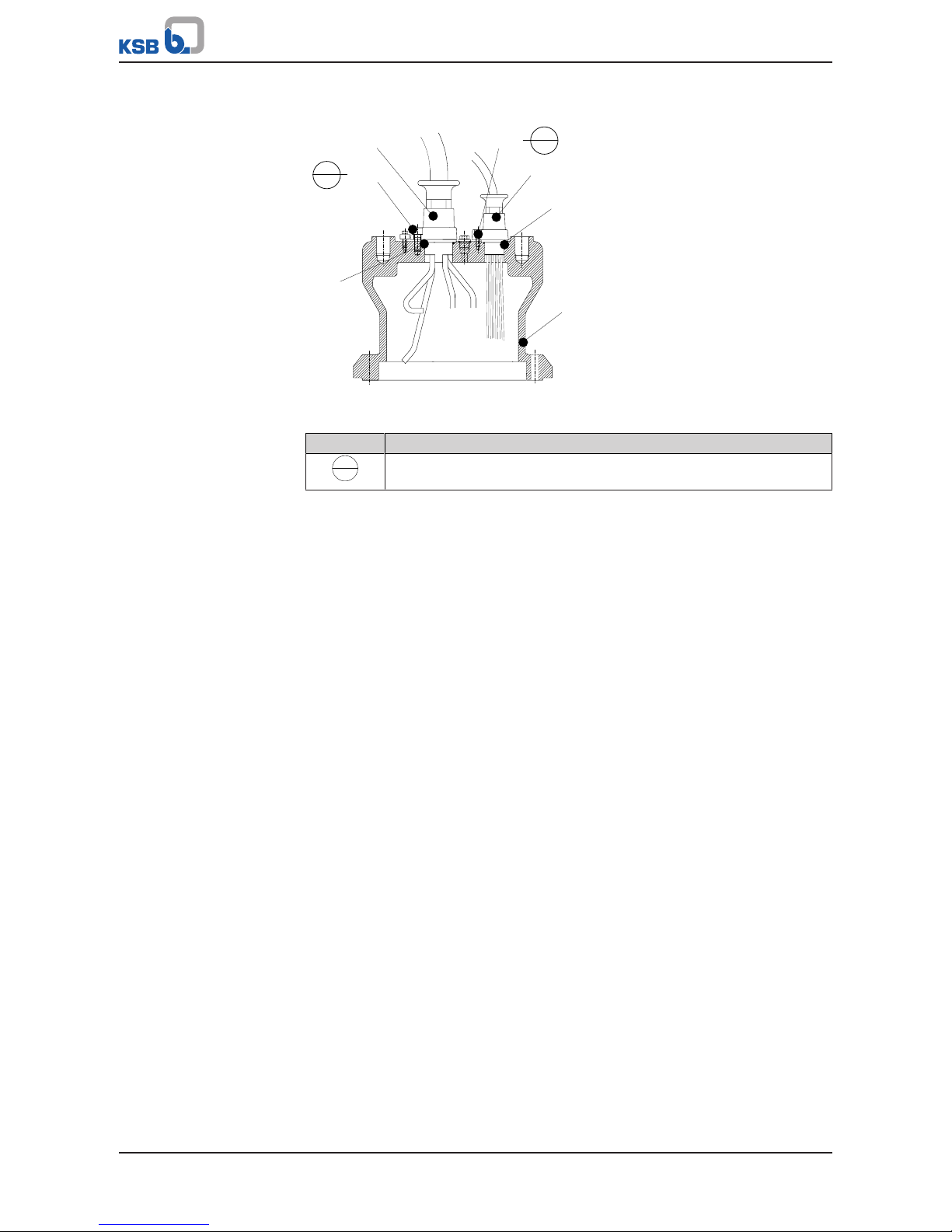
7 Servicing/Maintenance
68 of 132
Amacan P
7.6.2 Installing the replacement cable gland
412.07
914.04
834.01
412.08
914.05
834.02
812
L
243
L
243
Fig.39: Installing the cable gland
Table21: Key to the symbols and codes
Symbol Description
L
243
Always secure screwed connections marked with this symbol with
Loctite 243.
Connecting the power cable ü The motor housing cover has been removed, set down and protected against
rolling off.
1. Adjust the lengths of the cable cores to those of the original cable gland.
2. Attach the core identification to match the original cable gland.
3. Slide O-ring 412.07 onto the core ends of the power cable and into the groove
of the centring seat.
4. Insert cable gland 834.01 with the power cable and O-ring 412.07 into the
opening provided.
5. Fasten cable gland 834.01 with socket head cap screws 914.04 and secure the
screwed connection with Loctite 243.
6. Fasten cable terminals to the core ends.
Connecting the control
cable
ü The motor housing cover has been removed, set down and protected against
rolling off.
1. Adjust the lengths of the cable cores to those of the original cable gland.
2. Attach the core identification to match the original cable gland.
3. Guide O-ring 412.08 onto the short core ends of the control cable and into the
groove of the centring seat.
4. Insert cable gland 834.02 with the power cable and O-ring 412.08 into the
opening provided.
5. Fasten cable gland 834.02 with socket head cap screws 914.05 and secure the
screwed connection with Loctite 243.
Page 69
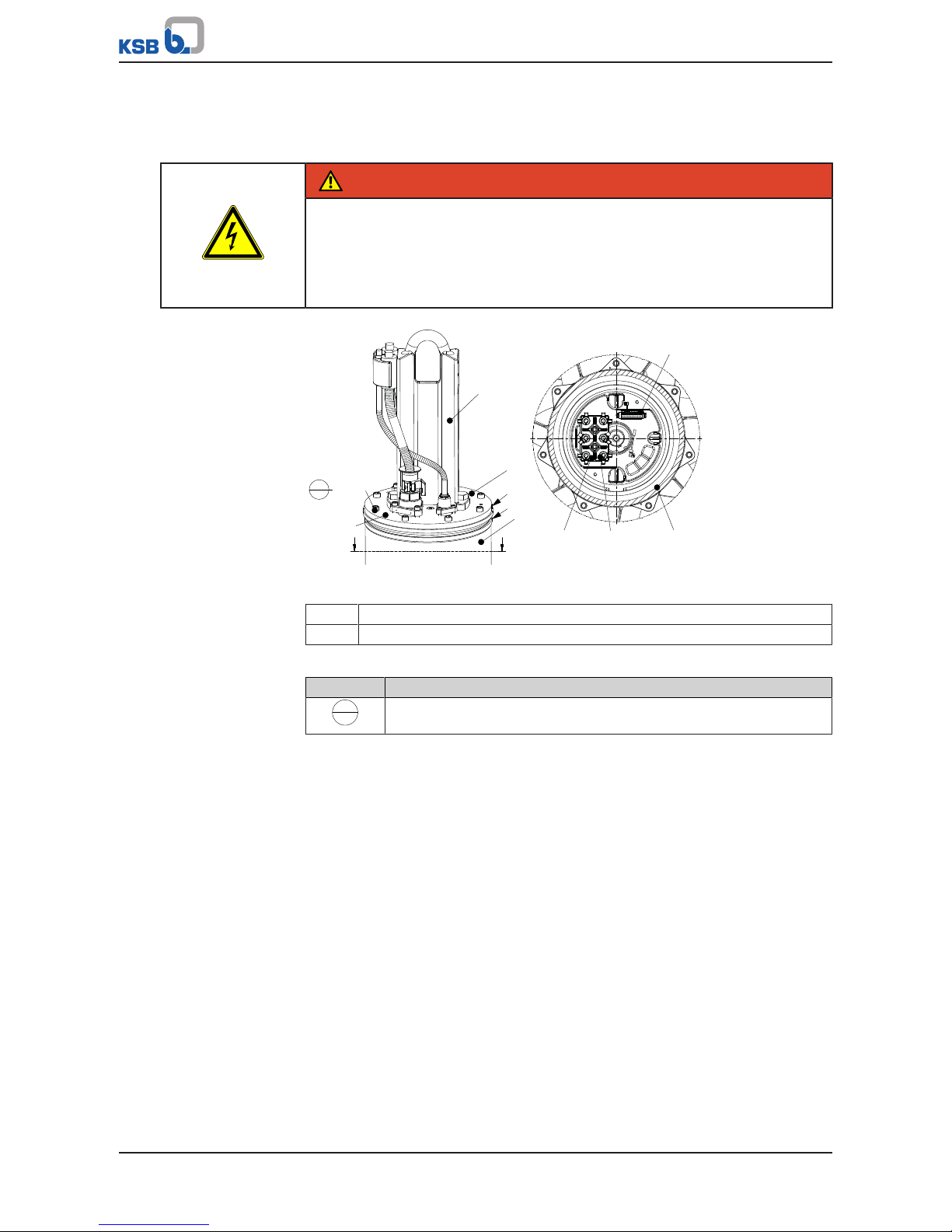
7 Servicing/Maintenance
69 of 132
Amacan P
7.6.3 Fitting the motor housing cover
7.6.3.1 Fitting the motor housing cover — pump sizes 700 to 1500
DANGER
Electrical connection work by unqualified personnel
Risk of fatal injury due to electric shock!
▷ Always have the electrical connections installed by a trained and qualified
electrician.
▷ Observe the IEC60364 regulations as well as any regional regulations.
571
811
80-1
a
b
812
914.01
903.51
811
80-1
550.23
920.23
920.24
932.23
835
81-2
A A
A - A
L
243
Fig.40: Fitting the motor housing cover
a Alignment grooves of motors housing cover 812
b Alignment groove of motor housing 811
Table22: Key to the symbols and codes
Symbol Description
L
243
Always secure screwed connections marked with this symbol with
Loctite 243.
ü A new O-ring has been inserted into the groove of motor housing cover 812.
1. Attach lifting equipment to eyebolt 900.04 or bail 571 of motor housing cover
812. Lift up the motor housing cover and lower it down onto motor housing 811
or motor unit 80-1 until only a gap remains which allows work to continue.
Watch the alignment grooves in motor housing cover 812 and motor housing
811. The alignment grooves must be properly aligned.
2. Connect plug 81-2 of the control cable to the corresponding connector.
3. Connect the power cable cores to terminal board 835 with disc 550.23, circlip
932.23 and nuts 920.23/920.24 in accordance with the wiring diagram.
4. Tie the cores of the control cable and power cable together with cable ties.
5. Slowly lower motor housing cover 812 onto motor housing 811. Watch the
alignment grooves in motor housing cover 812 and motor housing 811. The
alignment grooves must be properly aligned.
6. Fasten motor housing cover 812 to motor housing 811 or motor unit 80-1 with
socket head cap screws 914.01. Secure with Loctite243. Observe the tightening
torque! (ðSection7.8,Page79)
7. Cover the extraction threads with caps 903.51.
8. Perform a leak test on the motor. (ðSection7.6.7.2,Page78)
Page 70

7 Servicing/Maintenance
70 of 132
Amacan P
7.6.3.2 Fitting the motor housing cover — pump size 1600-...
DANGER
Electrical connection work by unqualified personnel
Risk of fatal injury due to electric shock!
▷ Always have the electrical connections installed by a trained and qualified
electrician.
▷ Observe the IEC60364 regulations as well as any regional regulations.
550.23
185
920
330
81-2
a
b
e
d c
A - A
571
812
811
80-1
903.51
914.01
A
A
Fig.41: Fitting the motor housing cover
a Alignment groove of motors housing cover 812
b Alignment groove of bearing bracket 330
c Anti-rotation device of bearing bracket 330
d Recess for anti-rotation device in motor housing cover 812
e Alignment groove of motor housing 811 or 80-1
Table23: Key to the symbols and codes
Symbol Description
L
243
Always secure screwed connections marked with this symbol with
Loctite 243.
ü A new O-ring has been inserted into the groove of bearing bracket 330.
1. Attach lifting tackle to bail 571, lift up motor housing cover 812 and lower it
down onto motor housing 811 or motor unit 80-1 until only a gap remains
which allows work to continue. Make sure that the alignment grooves of motor
housing 811 and bearing bracket 330 are correctly aligned. Only in this position
will the anti-rotation device (c) of bearing bracket 330 engage in the
corresponding recess (d) in motor housing cover 812.
2. Connect plug 81-2 of the control cable to the corresponding connector.
3. Connect the power cable cores to terminal 185 with disc 550.23 and nuts 920 in
accordance with the wiring diagram.
4. Tie the cores of the control and power cables together with cable ties.
5. Slowly lower motor housing cover 812 onto motor housing 811. Watch the
alignment grooves in motor housing cover 812 and motor housing 811. Line up
the grooves.
6. Fasten motor housing cover 812 to motor housing 811 or motor unit 80-1 with
socket head cap screws 914.01 and secure the connection with Loctite 243.
Observe the tightening torques! (ðSection7.8,Page79)
Page 71
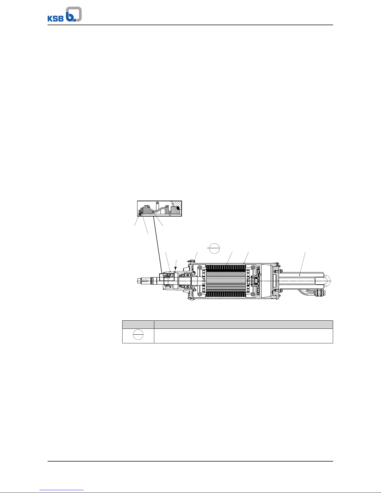
7 Servicing/Maintenance
71 of 132
Amacan P
7. Cover the jacking threads with caps 903.51.
8. Perform a leak test on the motor. (ðSection7.6.7.2,Page78)
7.6.4 Installing the mechanical seal
Observe the following to ensure trouble-free operation of the mechanical seal:
▪ Only remove the protective wrapping of the contact faces immediately before
assembly takes place.
▪ The shaft surface must be absolutely clean and undamaged.
▪ Immediately before installing the mechanical seal, wet the contact faces with a
drop of oil.
▪ For easier installation of bellows-type mechanical seals, wet the inside diameter
of the bellows or the O-rings with soapy water (not oil).
▪ Cover any grooves in the shaft into which the O-rings could slide with suitable
means or assembly aids.
▪ To prevent any damage to the rubber bellows, place a thin foil (of approximately
0.1 to 0.3 mm thickness) around the free shaft stub.
Slide the rotating assembly over the foil into its installation position.
Then remove the foil.
7.6.4.1 Drive-end mechanical seal — pump sizes 700-... to 1200-...
350 914.02 818 80-1 571
X
932.03
550.03
433.01
L
243
Fig.42: Installing the drive-end mechanical seal, X = drilled hole for testing device
Table24: Key to the symbols and codes
Symbol Description
L
243
Always secure screwed connections marked with this symbol with
Loctite 243.
ü The pump set has been positioned horizontally on suitable wooden supports and
is protected against rolling off.
1. Use an assembly sleeve of a suitable diameter to press the mating ring of
mechanical seal 433.01 together with the O-ring into the drilled seat of bearing
housing 350.
2. Carefully guide on the bellows part of mechanical seal 433.01 until it rests
against the mating ring.
3. Guide disc 550.03 and circlip 932.03 onto the shaft. Press the circlip in with an
assembly sleeve until it is axially fastened to the shaft groove.
4. Screw the testing device into the leakage drain hole (X) of bearing housing 350
and perform a leak test. (ðSection7.6.4.1.1,Page72)
Page 72
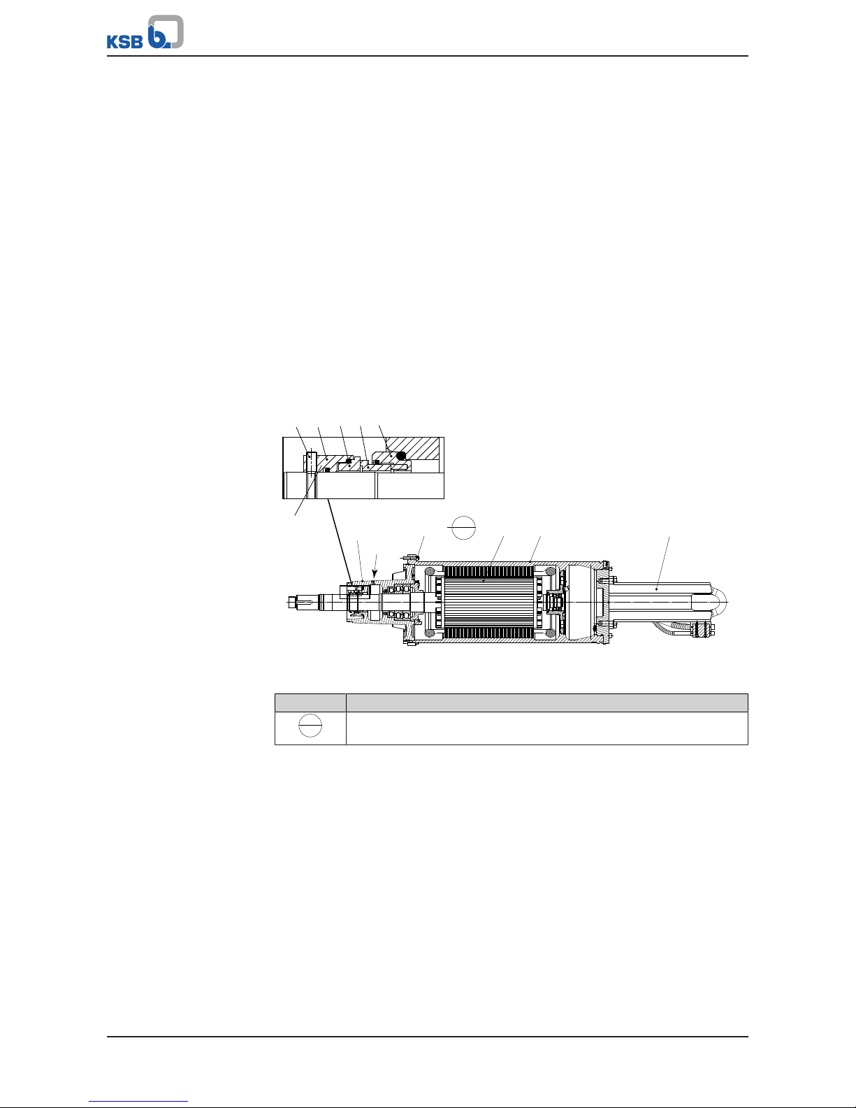
7 Servicing/Maintenance
72 of 132
Amacan P
5. Attach the crane hook to the bail and pull upright motor unit 80-1 including
rotor 818 with bearing and bearing housing 350. (ðSection3.2.2,Page12)
6. Place the pump set on the pump casing and bellmouth. Fasten it with hexagon
socket head cap screws 914.02. Secure the screwed connection with a threadlocking agent (Loctite 243).
7.6.4.1.1 Leak test when installing the mechanical seal
Observe the following values for leak testing:
▪ Test medium: compressed air
▪ Test pressure: 1 bar max.
▪ Test period: 5 minutes
1. The pressure must not drop during the test period.
If the pressure does drop, check the seals and screwed connections.
Then perform another leak test.
2. If the test has been successful, remove the testing device. Do not close the
leakage drain hole to allow drainage of any water ingress.
7.6.4.2 Drive-end mechanical seal — pump sizes 1500-... to 1600-...
350
914.02 818 80-1 571
X
abcde
433.01
L
243
Fig.43: Installing the drive-end mechanical seal, X = drilled hole for testing device
Table25: Key to the symbols and codes
Symbol Description
L
243
Always secure screwed connections marked with this symbol with
Loctite 243.
ü The pump set has been positioned horizontally on suitable wooden supports and
is protected against rolling off.
1. Press the supporting ring (a) and primary ring (b) of mechanical seal 433.01 into
the drilled hole of bearing housing 350 together with an O-ring.
2. Gently insert the mating ring (c) and the tappet (d) until they rest against the
primary ring (b).
3. Press the mechanical seal in with an assembly sleeve until the grub screws (e)
can be tightened in the undercut of the shaft. Apply a thread-locking agent
(Loctite 243) to the grub screws (e).
4. For mechanical seals with a stationary seat lock, bolt the stationary assembly
(supporting ring (a) and primary ring(b)) to bearing housing 350. Apply a
thread-locking agent (Loctite 243) to the screwed connection.
5. Screw the testing device into the leakage drain hole (X) of bearing housing 350
and perform a leak test. (ðSection7.6.4.1.1,Page72)
Page 73

7 Servicing/Maintenance
73 of 132
Amacan P
6. Attach the crane hook to bail 571 and pull upright motor unit 80-1 including
rotor 818 with bearing and bearing housing 350. (ðSection3.2.2,Page12)
7. Place the pump set on the pump bowl and bellmouth. Fasten it with hexagon
socket head cap screws 914.02. Secure it with a thread-locking agent (Loctite
243).
7.6.4.3 Impeller-end mechanical seal — pump sizes 700-... to 1200-...
932.44
550.44 433.02
Fig.44: Installing the impeller-end mechanical seal
ü The pump bowl has been fastened to the motor.
ü The pump set has been positioned horizontally on a wooden support. It has been
secured against rolling off.
1. Use an assembly sleeve of a suitable diameter to press the mating ring of
mechanical seal 433.02 together with the O-ring into the drilled recess in the
pump bowl.
2. Carefully guide on the bellows part of the mechanical seal until it rests against
the mating ring.
3. Slide disc 550.44 and circlip 932.44 onto the shaft. Press the circlip in with an
assembly sleeve until it is axially fastened in the shaft groove.
4. Check the lubricant reservoir for leakage. (ðSection7.6.7.1,Page77)
5. Fill the lubricant reservoir with lubricant. Then close the lubricant reservoir.
Page 74

7 Servicing/Maintenance
74 of 132
Amacan P
7.6.4.4 Impeller-end mechanical seal — pump sizes 1500-... to 1600-...
112
a
433.02
914.55
Fig.45: Impeller-end mechanical seal
Table26: Key to the symbols and codes
Symbol Description
L
243
Always secure screwed connections marked with this symbol with
Loctite 243.
ü The pump bowl has been fastened to the motor.
ü The pump set has been positioned horizontally on a wooden support. It has been
secured against rolling off.
1. Fasten the stationary assembly of mechanical seal 433.02 to pump bowl 112 with
hexagon socket head cap screw 914.55. Apply a thread-locking agent (Loctite
243) to hexagon socket head cap screw 914.55.
2. Slide the rotating assembly of mechanical seal 433.02 onto the shaft.
3. Press the mechanical seal in with an assembly sleeve until the grub screws (a)
can be tightened in the undercut of the shaft. Apply a thread-locking agent
(Loctite 243) to the grub screws (a).
4. Check the lubricant reservoir for leakage. (ðSection7.6.7.1,Page77)
5. Fill the lubricant reservoir with lubricant. Then close the lubricant reservoir.
Page 75

7 Servicing/Maintenance
75 of 132
Amacan P
7.6.5 Fitting the impeller
914.07
922
940.02
210
230
Fig.46: Fitting the impeller
ü The pump has been placed on a wooden support in a horizontal position and is
protected against rolling off.
ü The impeller-end mechanical seal 433.02 has been installed.
1. Insert and fit two keys 940.02 into the keyway.
2. Coat all sides of the shaft seat and shaft thread with an assembly paste which
prevents seizure of the chrome steel parts.
3. Guide impeller 230 onto shaft 210 until it abuts against the shaft collar.
4. Screw impeller nut 922 onto the shaft thread until impeller nut 922 and shaft
210 are aligned.
5. Align the holes of impeller 230 and impeller nut 922 and fasten them with
socket head cap screws 914.07.
Page 76

7 Servicing/Maintenance
76 of 132
Amacan P
7.6.6 Fitting the bellmouth
7.6.6.1 Fitting the bellmouth for pressure class A
920.01
550.01
138
112
502
903.05
Fig.47: Impeller of pressure class A
ü Bellmouth 138 has been positioned on wooden supports on a level and solid
surface.
ü Suitable lifting equipment is provided.
ü The pump set has been completely pre-assembled.
ü A new casing wear ring 502 has been fitted in bellmouth 138.
1. Attach the lifting tackle to bail 571 and carefully pull the pump set upright.
2. Centre the pump set above bellmouth 138.
Note: Make sure that the pin of bail 571 for attaching the lifting tackle and the
baffles in bellmouth 138 are aligned in the same direction.
3. Slowly lower the pump set. While lowering the pump set, make sure that studs
920.01 are aligned with the drilled holes.
4. Then lower the pump set until it sits on bellmouth 138.
5. Fasten all studs 902.01 with corresponding nuts 920.01 and discs 550.01.
Observe the tightening torque! (ðSection7.8,Page79)
6. Close the threaded holes with screw plugs 903.05.
Table27: Diameter of the casing wear ring [mm]
Size Nominal diameter
700 - 470 470 + 0,1
800 - 540 540 + 0,2
900 - 540 540 + 0,2
1000 - 700 700 + 0,3
1200 - 870 870 + 0,3
1500 - 1060 1060 + 0,3
1600 - 1060 1060 + 0,3
7.6.6.2 Fitting the bellmouth for pressure class B
At impellers of pressure class B, the outer contour of the vanes and the inner contour
of the casing wear ring are spherical.
For this pressure class the clearance is axially adjusted with the impeller nut.
Page 77

7 Servicing/Maintenance
77 of 132
Amacan P
502
112
138
901.01
922
903.06
914.07
230
902.01
920.01
550.01
Fig.48: Impeller of pressure class B
ü Bellmouth 138 has been positioned on wooden supports on a level and solid
surface.
ü Suitable lifting equipment is provided.
ü The pump set has been completely pre-assembled.
ü A new casing wear ring 502 has been fitted in bellmouth 138.
1. Attach the lifting tackle to bail 571 and carefully pull the pump set upright.
2. Centre the pump set above bellmouth 138.
Note: Make sure that the pin of bail 571 for attaching the lifting tackle and the
baffles in bellmouth 138 are aligned in the same direction.
3. Slowly lower the pump set. While lowering the pump set, make sure that studs
920.01 are aligned with the drilled holes.
4. Then lower the pump set until it sits on bellmouth 138.
5. Fasten all studs 902.01 with corresponding nuts 920.01 and discs 550.01.
Observe the tightening torque! (ðSection7.8,Page79)
6. Close the threaded holes with screw plugs 903.05.
7. Loosen the impeller nut to adjust clearance "A" between impeller 230 and
casing wear ring 502.
8. Use a sensor to check that the required clearance "A" is met, see the following
table.
9. Align the holes of impeller 230 and impeller nut 922. Insert and tighten socket
head cap screw 914.07.
Table28: Clearance "A" [mm]
Size Standard dimension A Increased clearance A
7)
700 - 470 0,4 1,2
800 - 540 0,5 1,3
900 - 540 0,5 1,5
1000 - 700 0,7 1,7
1200 - 870 0,9 2,0
1500 - 1060 1,1 2,0
1600 - 1060 1,1 2,0
7.6.7 Leak testing
7.6.7.1 Testing the lubricant reservoir for leakage
After reassembly, the mechanical seal area/lubricant reservoir must be checked for
leakage. The leak test is performed at the lubricant filler opening.
7) For activated sludge or fluids containing long fibres
Page 78

7 Servicing/Maintenance
78 of 132
Amacan P
Observe the following values for leak testing:
▪ Test medium: compressed air
▪ Test pressure: 1 bar maximum
▪ Test duration: 5 minutes
p
1,0 bar
Fig.49: Screwing in the testing device
1. Unscrew and remove the screw plug and joint ring of the lubricant reservoir.
2. Screw the testing device tightly into the lubricant filler opening.
3. Carry out the leak test with the values specified above.
The pressure must not drop during the test period.
If the pressure does drop, check the seals and screwed connections.
Then perform another leak test.
4. If the leak test has been successful, fill in the lubricant.
(ðSection7.4.1.4.2,Page58)
7.6.7.2 Checking the motor for leakage
Observe the following values for leak testing:
▪ Test medium: nitrogen
▪ Test pressure: 0.8 bar maximum
▪ Test duration: 2 minutes
903.31
411.31
L
243
FD
Fig.50: Checking the motor for leakage
Page 79

7 Servicing/Maintenance
79 of 132
Amacan P
Table29: Key to the symbols and codes
Symbol Description
L
243
Always secure screwed connections marked with this symbol with
Loctite243.
FD
Always apply a liquid sealant (e.g. Hylomar SQ32M) to sealing surfaces
marked with this symbol.
1. Undo and remove screw plug 903.31 and joint ring 411.31.
2. Screw the testing device tightly into the G 1/2 plug thread.
3. Carry out the leak test with the values specified above.
ð The pressure must not drop during the test period.
ð If the pressure does drop, check the seals and screwed connections.
4. Repeat the leak test if required.
5. Remove the testing device.
DANGER
Screw plug leaking or missing
Explosion hazard!
Damage to the motor!
▷ Never start up a pump set without screw plug 903.31.
▷ Apply a thread-locking agent (Loctite 243) to screw plug 903.31.
6. Apply a thread-locking agent (Loctite 243) to screw plug 903.31.
7. Re-insert and tighten screw plug 903.31 with new joint ring 411.31.
7.7 Checking the electrical connection and motor
Once reassembly has been completed, carry out the steps described in
(ðSection7.2.1,Page51) and (ðSection7.3.4,Page55) .
7.8 Tightening torques
Table30: Tightening torques [Nm] depending on thread, steel grade and property class
Steel grade - A2, A4 A2, A4 1.4410 1.4462
Property class 8.8 -50 -70 R
p0.2
≥ 530 N/mm2R
p0,2
≥ 450 N/mm
2
Thread
Minimum
Rated
torque
Minimum
Rated
torque
Minimum
Rated
torque
Minimum
Rated
torque
Minimum
Rated
torque
M4 3,0 3,4 1,0 1,1 2,1 2,4 2,5 2,8 2,1 2,4
M5 6,1 6,8 2,0 2,2 4,3 4,8 5,0 5,6 4,3 4,8
M6 10.3 11 3,4 3,7 7,2 8,0 8,5 9,5 7,2 8,0
M8 25 28 8,2 9,1 18 19 21 23 18 19
M10 49 55 16 18 35 38 41 45 35 38
M12 85 94 28 31 59 66 70 78 59 66
M14 134 149 44 49 94 105 111 124 94 105
M16 209 232 69 76 147 163 173 192 147 163
M20 408 453 134 149 287 319 338 375 287 319
M24 704 782 231 257 495 550 583 648 495 550
M27 1025 1139 36 374 721 801 849 944 721 801
M30 1403 1559 460 511 986 1096 1162 1291 986 1096
M33 1888 2098 619 688 1327 1475 1563 1737 1327 1475
M36 2445 2717 802 891 1719 1910 2025 2250 1719 1910
Page 80

7 Servicing/Maintenance
80 of 132
Amacan P
Steel grade - A2, A4 A2, A4 1.4410 1.4462
Property class 8.8 -50 -70 R
p0.2
≥ 530 N/mm2R
p0,2
≥ 450 N/mm
2
Thread
Minimum
Rated
torque
Minimum
Rated
torque
Minimum
Rated
torque
Minimum
Rated
torque
Minimum
Rated
torque
M42 3904 4338 1281 1423 2745 3050 3233 3592 2745 3050
M48 5880 6534 1929 2144 4135 4594 4870 5411 4135 4594
NOTE
If using an adjustable torque wrench or screwdriver, adjust it to a value within the
indicated range between the minimum and the rated torque.
7.9 Spare parts stock
7.9.1 Ordering spare parts
Always quote the following data when ordering replacement or spare parts:
▪ Order number
▪ Order item number
▪ Type series
▪ Size
▪ Year of construction
▪ Motor number
Refer to the name plate for all data.
Also specify the following data:
▪ Part number and description
▪ Quantity of spare parts
▪ Shipping address
▪ Mode of dispatch (freight, mail, express freight, air freight)
7.9.2 Recommended spare parts stock for 2 years' operation to DIN24296
Table31: Quantity of spare parts for recommended spare parts stock
Part No. Description Number of pumps (including stand-by pumps)
2 3 4 5 6 8 10 and
more
230 Impeller 1 1 1 2 2 3 30 %
320 /
321
Rolling element bearing,
pump end
1 1 2 2 3 4 50 %
322 Rolling element bearing,
drive end
1 1 2 2 3 4 50 %
412.05 /
412.60
O-ring,
for discharge tube cover
2 3 4 5 6 8 100 %
433.01 Mechanical seal, drive end 2 3 4 5 6 7 90 %
433.02 Mechanical seal, pump end 2 3 4 5 6 7 90 %
502 Casing wear ring 2 2 2 3 3 4 50 %
80-1 Motor unit - - - - 1 2 30 %
818 Rotor - - - - 1 2 30 %
834 Cable gland 1 1 2 2 2 3 40 %
Page 81

7 Servicing/Maintenance
81 of 132
Amacan P
Part No. Description Number of pumps (including stand-by pumps)
2 3 4 5 6 8 10 and
more
99-9 Set of sealing elements,
motor
4 6 8 8 9 10 100 %
99-9 Set of sealing elements,
hydraulic system
4 6 8 8 9 10 100 %
Page 82

8 Trouble-shooting
82 of 132
Amacan P
8 Trouble-shooting
WARNING
Improper work to remedy faults
Risk of injury!
▷ For any work performed to remedy faults, observe the relevant information
given in this operating manual and/or in the product literature provided by the
accessories manufacturer.
If problems occur that are not described in the following table, consultation with the
KSB customer service is required.
A Pump is running, but does not deliver
B Pump delivers insufficient flow rate
C Excessive current/power input
D Insufficient discharge head
E Vibrations and noise during pump operation
Table32: Trouble-shooting
A B C D E Possible causes Remedy
8)
- ✘ - - ✘ Water level lowered too much during operation Check supply and capacity of system (sump floor
area).
Check level control equipment.
✘ ✘ - - ✘ Total pressure corresponding to NPSH
pump
too
high
Total pressure corresponding to NPSH
system
too
low
Increase fluid level on the suction side.
Clean screening equipment, if required.
✘ ✘ ✘ - ✘ Penetration of air into the pump due to
formation of an air pocket
- Suction-side water level too low
Increase the suction-side water level. If this is
not possible or unsuccessful, please contact KSB.
✘ ✘ ✘ - ✘ Unfavourable flow to the pump inlet Improve the flow to the intake chamber (contact
KSB).
- ✘ ✘ - ✘ Pump running in off-design conditions
- part load/overload
Check the pump's operating data.
✘ ✘ - ✘ ✘ Pump clogged by deposits Clean intake and pump components.
- ✘ ✘ ✘ ✘ Wear Replace worn components by new ones.
- ✘ - ✘ ✘ Impermissible air or gas content in the fluid
handled
Contact KSB.
- - - - ✘ System-induced vibrations Contact KSB.
- - ✘ - ✘ Wrong direction of rotation Check the electrical connection of motor and
control system, if any.
✘ - - - - No voltage Check electrical connections.
Contact the energy supplier.
✘ - - - - Motor winding or electric cable are defective. Replace with original KSB cable or contact KSB.
- - ✘ - ✘ Worn or defective rolling element bearings Contact KSB.
✘ - - - - The thermistor tripping unit with manual reset
for temperature limiter has tripped the pump as
a result of the permissible winding temperature
being exceeded.
Have cause determined and eliminated by
qualified and trained personnel.
✘ - - - - Motor has been tripped
by leakage monitor.
Have cause determined and eliminated by
qualified and trained personnel.
8) The pump pressure must be released before attempting to remedy faults on parts which are subjected to pressure.
Disconnect the pump set from the power supply!
Page 83

8 Trouble-shooting
83 of 132
Amacan P
A B C D E Possible causes Remedy
8)
✘ - - - - Mechanical seal monitor has tripped. Have cause determined and eliminated by
qualified and trained personnel.
✘ - - - - Bearing temperature monitor has tripped. Have cause determined and eliminated by
qualified and trained personnel.
Page 84

9 Related Documents
84 of 132
Amacan P
9 Related Documents
9.1 General assembly drawing
922
940.02
138
230
412.03
112
350
412.05
914.02
914.03
818
80-1
330
932.37
812
412.01
L
243
FD
FD
L
243
FD
GP
Q NB 50
914.25
82-11
571
81-18.03
901.20
932.20
360
412.02
320
321
421.02
500.02
932.02
433.01
550.03
932.03
932.44
550.44
433.02
502
904.01
Fig.51: General assembly drawing
Page 85

9 Related Documents
85 of 132
Amacan P
Table33: Detailed views of the general assembly drawing
Connection of cable
gland
and fastening
Motor sizes:
47 6 ... 205 6
30 8 ... 160 8
60 10 ... 120 10
81-97.01
81-97.02
914.04
834.01
412.07
914.01
914.05
834.02
412.08
903.31
411.31
82-11
903.51
901.26
L
243
L
243
L
243
L
243
L
243
Motor sizes:
205 8 ... 290 8
200 10 ... 470 10
130 12 ... 680 12
210 14 ... 440 14
81-97.02
571
81-97.01
68-3.02
914.01
901.26
903.31
411.31
901.25
920.25
550.25
903.51
L
243
L
243
L
243
Bearing temperature
sensors
Motor end
69-6.01
520.01
Pump end
69-6.02
520.02
Page 86

9 Related Documents
86 of 132
Amacan P
Table34: Detailed views of the general assembly drawing
Bearing, motor end Motor sizes:
47 6 ... 205 6
30 8 ... 290 8
60 10 ... 250 10
130 12 ... 190 12
421.01 932.01500.01
322
932.13 500.04
932.05
500.29
932.29
Motor sizes:
310 10 ... 470 10
250 12 ... 410 12
210 14 ... 240 14
421.01
500.01
932.01
932.05
322 932.13 500.04 932.01
550.05
901.05
Motor sizes:
450 12 ... 680 12
370 14 ... 440 14
69-6.01
520.01
322
81-97.11
932.01
932.29
500.29
932.25
932.13
500.01
932.01
932.38
421.01
Page 87

9 Related Documents
87 of 132
Amacan P
Table35: Detailed views of the general assembly drawing
Bearing, pump end Motor sizes:
47 6 ... 205 6
30 8 ... 290 8
60 10 ... 470 10
130 12 ... 410 12
210 14 ... 340 14
932.02 500.02 421.02 321 320
Motor sizes:
450 12 ... 680 12
370 14 ... 440 14
484.02412.57 950.02 483.02 561.02
932.02 512.02
421.02
504.02321
320 932.12
50-3.12
Sensors, bearing
housing
99-17
81-2.02
900.26
932.26
69-14.02
99-4.02
1)
81-45
81-29.02
1)
Only for versions with vibration sensor 69-8.50
Page 88

9 Related Documents
88 of 132
Amacan P
Table36: Detailed views of the general assembly drawing
Sensors/terminals,
bearing bracket
Motor sizes:
47 6 ... 205 6
30 8 ... 290 8
60 10 ... 470 10
130 12 ... 410 12
210 14 ... 340 14
69-14.01
900.06
932.06
81-2.01
81-29.01
81-2.03***
900.06***
932.06***
82-5.51**
914.51**
69-8.50**
82-5.50**
82-14.50**
550.50**
835
185.36
81-18.01
81-18.02
550.23
920.23
920.24
932.23
914.19
932.19***
99-4.01**
99-17.01
900.30
914.48
H
L
243
L
243
** Only for variants with vibration sensor 69-8.50
*** Only on specific sizes
H = alignment groove
Motor sizes:
450 12 ... 680 12
370 14 ... 440 14
561.01
81-29.01
81-2.01
900.06
932.06
81-39
914.19
932.19
81-92.52
914.52
900.30
99-17
81-2.03**
900.06**
932.06**
69-8.50**
82-5.50**
82-14.50**
550.50**
99-4.01**
69-14.01
82-5.51**
914.51**
K
K
H
** Only for variants with vibration sensor 69-8.50
H = alignment groove
550.23
81-18.02
81-29.04
185
81-65
81-18.01
550.23/
81-18.01
K - K
Page 89
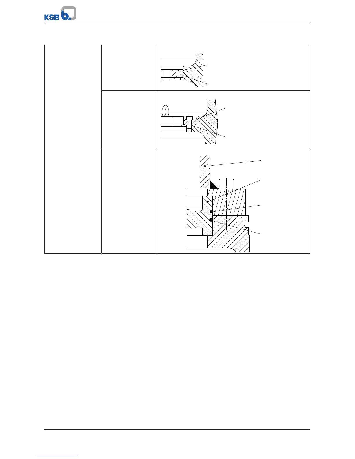
9 Related Documents
89 of 132
Amacan P
Table37: Detailed views of the general assembly drawing
Bearing bracket
fastening
Motor sizes:
47 6 ... 205 6
30 8 ... 160 8
60 10 ... 120 10
932.37
330
Motor sizes:
205 8 ... 290 8
155 10 ... 470 10
130 12 ... 410 12
210 14 ... 340 14
330
914.48
Motor sizes:
450 12 ... 680 12
370 14 ... 440 14
812
330
412.01
412.12
Page 90

9 Related Documents
90 of 132
Amacan P
Table38: Detailed views of the general assembly drawing
Screwed connection
bellmouth / pump bowl
903.05
902.01
920.01
550.01
112
138
Impeller fasteners
914.07
Float switch
81-45
411.26
Lubricant and leakage
chamber
903.01
411.01
903.03
903.02
411.02
FD
FD
Page 91

9 Related Documents
91 of 132
Amacan P
Table39: Detailed views of the general assembly drawing
Labels/plates
970.01
970.22
970.02
970.05
970.04
970.03
Table40: Key to the symbols and codes
Symbol Description
L
243
Always secure screwed connections marked with this symbol with
Loctite 243.
FD
Always apply a liquid sealing agent (e.g. Hylomar SQ32M) to sealing
surfaces marked with this symbol.
GP
Q NB 50
Use a lubricant paste (e.g. Altemp Q NB 50).
Table41: List of components
Part No. Description Part No. Description
112 Pump bowl 81-18.01/.02 Cable terminal
138 Bellmouth 81-2.01/.02/.03 Plug
185 Plate 81-29.01/.02/.04 Terminal
230 Impeller 81-39 Clamp
320 Angular contact ball bearing 81-45 Float switch
321 Deep groove ball bearing 81-65 Star connector
322 Radial roller bearing 81-92 Cover plate
330 Bearing bracket 81-97.01/.02/.11 Cable protector
350 Bearing housing 82-5.50/.51 Adapter
360 Bearing cover 82-11 Strain relief device
411.01/.02/.26/.31 Joint ring 82-14.50 Cable with plug
412.01/.02/.03/.05/.07/.08. O-ring 812 Motor housing cover
421.01/.02 Lip seal 818 Rotor
433.01/.02 Mechanical seal 834.01/.02 Cable gland
50-3.12 Backing ring 835 Terminal board
500.01/.02/.04/.29 Ring 99-4.01/02 Conversion kit
502 Casing wear ring 99-17 Desiccant
504.02 Spacer ring 900.06/.26/.30 Stud
512.02 Wear ring 901.05/.20/.25/.26 Hexagon head bolt
Page 92

9 Related Documents
92 of 132
Amacan P
Part No. Description Part No. Description
520.01/.02 Sleeve 902.01 Stud
550.01/.03/.05/.23/.25/.44/.50Disc 903.01/.02/.03/.05/.31/.51 Screw plug
561.01 Grooved pin 904.01 Grub screw
571 Bail 914.01/.02/.03/.04/.05/.07/.
19/.25/.48/.51/.52
Hexagon socket head cap
screw
68-3 Cover plate 920.01/.23/.24/.25 Nut
69-6 Temperature sensor 922 Impeller nut
69-8 Sensor 932.01/.02/.03/.05/.06/.12/.
13/.19/.20/.23/.25/.26/.29/.3
7/38/..44
Circlip
69-14 Leakage monitor 940.02 Key
80-1 Motor unit 970.01/.02/.03/.04/.05/.22 Label/plate
Page 93

9 Related Documents
93 of 132
Amacan P
9.1.1 Special features
Table42: Special features
Description Detailed view
Terminal block for
R35 motors
310 10 ... 470 10
250 12 ... 410 12
210 14 ... 340 14
*914.50
900.30
*68-3.03
*826
243
L
* Explosion-proof variants only
Hydraulic system
112
502
230
138
Hydraulic system A
230230
502
138
112
Hydraulic system B
Model with
adapter
112
914.02
82-5
412.06
80-1
914.06
L
243
L
243
Table43: Key to the symbols and codes
Symbol Description
L
243
Always secure screwed connections marked with this symbol with
Loctite 243.
Part No. Description Part No. Description
112 Pump bowl 502 Casing wear ring
138 Bellmouth 80-1 Motor unit
Page 94

9 Related Documents
94 of 132
Amacan P
Part No. Description Part No. Description
230 Impeller 82-5 Adapter
412.06 O-ring 914.02/.06/.50 Hexagon socket head cap
screw
9.2 Cable bundle
59-8
59-17.02
(59-47)
733.05
719.05
720
59-24
733.05
719.05
59-17.01
59-8
59-17.02
(59-47)
733.05
719.05
720
59-24
59-17.01
(59-47)
720
59-8
59-17.02
(59-47)
733.05
719.05
720
59-24
59-17.01
59-7
(59-47)
A A
*)
*)
*)
1)
2)
3)
M
M
M
MM
M
M
M
M
M
A A
A A
L
243
L
243
L
243
Fig.52: Cable bundle
1) Basic design
2) Design with lifting lug
3) Design with support
*): Only required for galavanised version (ðSection5.3.3,Page27)
NOTE
Distance M = 50mm
Table44: Key to the symbols and codes
Symbol Description
L
243
Always secure screwed connections marked with this symbol with
Loctite 243.
Page 95

9 Related Documents
95 of 132
Amacan P
733.05
A - A
720
59-24
719.05
d
c
Fig.53: Cross-section A - A, position of power cable, control cable and support rope
c Power cable d Control cable
Table45: List of components of the cable bundle
Part No. Description Part No. Description
59-7 Support 59-47 Lifting lug
59-8 Turnbuckle 719.05 Sheath
59-17.01/.02 Shackle 720 Fitting
59-24 Rope / support rope 733.05 Cable clamp
Page 96

9 Related Documents
96 of 132
Amacan P
9.3 Wiring diagrams
9.3.1 Wiring diagram for the power cable 700-470…1500-1060
Fig.54: Wiring diagram for the power cable 700-470…1500-1060
* Shielded cable optional
1)
Up to 3 parallel cable pairs possible
Page 97

9 Related Documents
97 of 132
Amacan P
9.3.2 Wiring diagram for the power cable 1600-1060
Fig.55: Wiring diagram for the power cable 1600-1060
* Shielded cable optional
1)
Up to 8 parallel cable pairs possible
Page 98

9 Related Documents
98 of 132
Amacan P
9.3.3 Wiring diagrams for the sensors
Standard
pump sets
Fig.56: Wiring diagram for sensors of standard pump sets
* Shielded cables optional
Ⓐ Motor temperature (PTC)
Ⓑ Mechanical seal leakage
Ⓒ Bearing temperature (lower bearings)
Ⓓ Bearing temperature (upper bearing, optional)
Ⓕ Leakage inside the motor
Page 99

9 Related Documents
99 of 132
Amacan P
Pump sets with additional
monitoring by vibration
sensor
Fig.57: Wiring diagram for sensors of pump sets with additional monitoring by
vibration sensor
Ⓐ Motor temperature (PTC)
Ⓑ Mechanical seal leakage
Ⓒ Bearing temperature (lower bearings)
Ⓓ Bearing temperature (upper bearing, optional)
Ⓕ Leakage inside the motor
Ⓖ Vibration sensor
Page 100

9 Related Documents
100 of 132
Amacan P
Pump sets with additional
Pt100 motor temperature
monitoring
Fig.58: Wiring diagram for sensors of pump sets with additional motor temperature
monitoring (Pt100)
Ⓐ Motor temperature (PTC)
Ⓑ Mechanical seal leakage
Ⓒ Bearing temperature (lower bearings)
Ⓓ Bearing temperature (upper bearing, optional)
Ⓕ Leakage inside the motor
Ⓗ Motor temperature (Pt100)
 Loading...