

KSB Amacan P 1200-870, Amacan P series, Amacan P 1500-1060, Amacan P 1600-1060, Amacan P 900-540 Installation & Operating Manual
...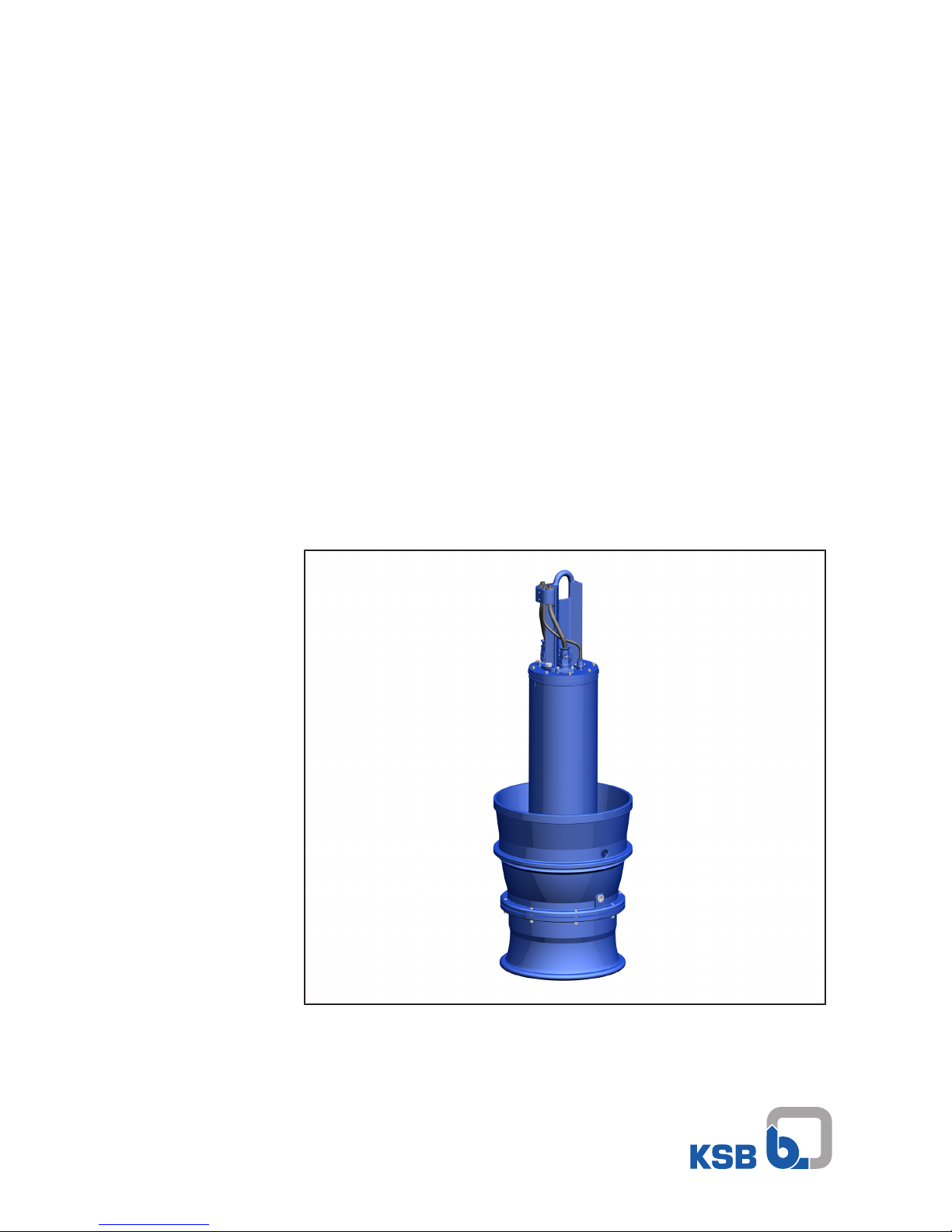
Submersible Pump in Discharge Tube
Amacan P
50 Hz
Amacan P 700 - 470
Amacan P 800/900 - 540
Amacan P 1000 - 700
Amacan P 1200 - 870
Amacan P 1500/1600 - 1060
Installation/Operating Manual
Mat. No.: 01137299

Legal information/Copyright
Installation/Operating Manual Amacan P
Original operating manual
All rights reserved. The contents provided herein must neither be distributed, copied, reproduced,
edited or processed for any other purpose, nor otherwise transmitted, published or made available to a
third party without the manufacturer's express written consent.
Subject to technical modification without prior notice.
© KSB SE & Co. KGaA, Frankenthal 03/09/2018

Contents
3 of 132
Amacan P
Contents
1 General.................................................................................................................................................... 7
1.1 Principles ...........................................................................................................................................................7
1.2 Installation of partly completed machinery....................................................................................................7
1.3 Target group.....................................................................................................................................................7
1.4 Other applicable documents............................................................................................................................7
1.5 Symbols .............................................................................................................................................................7
2 Safety...................................................................................................................................................... 8
2.1 Key to safety symbols/markings.......................................................................................................................8
2.2 General..............................................................................................................................................................8
2.3 Intended use .....................................................................................................................................................9
2.4 Personnel qualification and training...............................................................................................................9
2.5 Consequences and risks caused by non-compliance with this manual .........................................................9
2.6 Safety awareness ..............................................................................................................................................9
2.7 Safety information for the operator/user.......................................................................................................9
2.8 Safety information for maintenance, inspection and installation ..............................................................10
2.9 Unauthorised modes of operation................................................................................................................10
2.10 Explosion protection ......................................................................................................................................10
2.10.1 Repair..................................................................................................................................................11
3 Transport/Temporary Storage/Disposal............................................................................................. 12
3.1 Checking the condition upon delivery..........................................................................................................12
3.2 Transport.........................................................................................................................................................12
3.2.1 Transporting the delivered pump to the place of installation .......................................................12
3.2.2 Placing the pump set in a vertical or horizontal position ...............................................................12
3.2.3 Transporting the pump set................................................................................................................14
3.2.4 Transport lock ....................................................................................................................................15
3.3 Storage/preservation......................................................................................................................................15
3.4 Return to supplier...........................................................................................................................................16
3.5 Disposal ...........................................................................................................................................................17
4 Description of the Pump (Set)............................................................................................................. 18
4.1 General description ........................................................................................................................................18
4.2 Designation.....................................................................................................................................................18
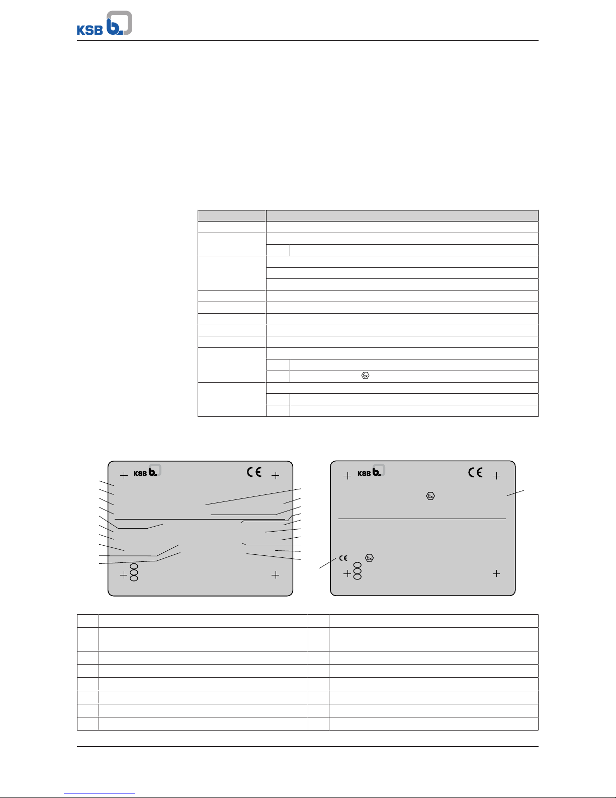
4.3 Name plate......................................................................................................................................................18
4.4 Design details..................................................................................................................................................19
4.5 Installation types ............................................................................................................................................19
4.6 Configuration and function...........................................................................................................................20
4.7 Scope of supply...............................................................................................................................................21
4.8 Dimensions and weights ................................................................................................................................21
5 Installation at Site................................................................................................................................ 22
5.1 Safety regulations...........................................................................................................................................22
5.2 Checks to be carried out prior to installation...............................................................................................22
5.2.1 Checking the structural requirements ..............................................................................................22
5.2.2 Checking the operating data ............................................................................................................22
5.2.3 Checking the lubricant of the mechanical seal ................................................................................22
5.2.4 Checking the direction of rotation ...................................................................................................23
5.3 Lowering the pump set into the discharge tube..........................................................................................25
5.3.1 Information for correct installation..................................................................................................26
5.3.2 Installation without support rope ....................................................................................................26
5.3.3 Installation with a support rope .......................................................................................................27
5.3.4 Installation with a support rope and support spacer ......................................................................30
5.4 Electrical system..............................................................................................................................................35
5.4.1 Information for planning the control system ..................................................................................35
5.4.2 Electrical connection..........................................................................................................................41

Contents
4 of 132
Amacan P
6 Commissioning/Start-up/Shutdown................................................................................................... 43
6.1 Commissioning/Start-up.................................................................................................................................43
6.1.1 Prerequisites for commissioning/start-up .........................................................................................43
6.1.2 Start-up...............................................................................................................................................44
6.2 Operating limits..............................................................................................................................................44
6.2.1 Operation on the power supply mains.............................................................................................44
6.2.2 Frequency of starts.............................................................................................................................45
6.2.3 Operation on a frequency inverter...................................................................................................45
6.2.4 Fluid handled .....................................................................................................................................45
6.3 Shutdown/storage/preservation ....................................................................................................................47
6.3.1 Shutdown ...........................................................................................................................................47
6.3.2 Measures to be taken for shutdown ................................................................................................47
6.4 Returning to service .......................................................................................................................................48
7 Servicing/Maintenance........................................................................................................................ 49
7.1 Safety regulations...........................................................................................................................................49
7.2 Maintenance/inspection.................................................................................................................................51
7.2.1 Inspection work..................................................................................................................................51
7.3 Removing the pump set.................................................................................................................................53
7.3.1 Removing the pump set ....................................................................................................................53
7.3.2 Drainage/cleaning..............................................................................................................................54
7.3.3 Checking the cable bundle................................................................................................................54
7.3.4 Checking the earth conductor ..........................................................................................................55
7.3.5 Checking the mechanical seal for leakage .......................................................................................55
7.4 Lubrication and lubricant change .................................................................................................................56
7.4.1 Lubricating the mechanical seal........................................................................................................56
7.4.2 Lubricating the rolling element bearings.........................................................................................59
7.5 Dismantling the pump set..............................................................................................................................60
7.5.1 General information/Safety regulations...........................................................................................60
7.5.2 Preparing the pump set.....................................................................................................................61
7.5.3 Removing the bellmouth...................................................................................................................61
7.5.4 Removing the impeller ......................................................................................................................62
7.5.5 Removing the mechanical seal..........................................................................................................62
7.5.6 Dismantling the motor section .........................................................................................................64
7.6 Reassembling the pump set...........................................................................................................................66
7.6.1 General information/Safety regulations...........................................................................................66
7.6.2 Installing the replacement cable gland ............................................................................................68
7.6.3 Fitting the motor housing cover .......................................................................................................69
7.6.4 Installing the mechanical seal ...........................................................................................................71
7.6.5 Fitting the impeller............................................................................................................................75
7.6.6 Fitting the bellmouth ........................................................................................................................76
7.6.7 Leak testing........................................................................................................................................77
7.7 Checking the electrical connection and motor.............................................................................................79
7.8 Tightening torques.........................................................................................................................................79
7.9 Spare parts stock.............................................................................................................................................80
7.9.1 Ordering spare parts..........................................................................................................................80
7.9.2 Recommended spare parts stock for 2 years' operation to DIN24296 ..........................................80
8 Trouble-shooting.................................................................................................................................. 82
9 Related Documents.............................................................................................................................. 84
9.1 General assembly drawing.............................................................................................................................84
9.1.1 Special features..................................................................................................................................93
9.2 Cable bundle...................................................................................................................................................94
9.3 Wiring diagrams .............................................................................................................................................96
9.3.1 Wiring diagram for the power cable 700-470…1500-1060.............................................................96
9.3.2 Wiring diagram for the power cable 1600-1060..............................................................................97
9.3.3 Wiring diagrams for the sensors .......................................................................................................98
9.4 Flamepaths on explosion-proof motors......................................................................................................102
9.5 Dimensions....................................................................................................................................................103

Contents
5 of 132
Amacan P
9.6 Wiring diagrams ...........................................................................................................................................107
9.6.1 Installation type BU .........................................................................................................................107
9.6.2 Installation type BG .........................................................................................................................110
9.6.3 Installation type CU .........................................................................................................................112
9.6.4 Installation type CG .........................................................................................................................115
9.6.5 Installation type DU.........................................................................................................................118
9.6.6 Installation type DG.........................................................................................................................121
9.6.7 Dimensions of the flow-straightening vane...................................................................................124
10 EU Declaration of Conformity........................................................................................................... 126
11 Certificate of Decontamination......................................................................................................... 127
Index ................................................................................................................................................... 128

Glossary
6 of 132
Amacan P
Glossary
Certificate of decontamination
A certificate of decontamination is enclosed by the
customer when returning the product to the
manufacturer to certify that the product has been
properly drained to eliminate any environmental
and health hazards arising from components in
contact with the fluid handled.
Close-coupled design
Motor directly fitted to the pump via a flange or a
drive lantern
ECB (ever clean blade) design
Self-cleaning vane profile
Submersible pump in discharge tube
A submersible motor pump which is completely
submerged and suspended in a discharge tube
1 General
7 of 132
Amacan P
1 General
1.1 Principles
This operating manual is supplied as an integral part of the type series and variants
indicated on the front cover.
The manual describes the proper and safe use of this equipment in all phases of
operation.
The name plate indicates the type series and size, the main operating data, the order
number and the order item number. The order number and order item number
clearly identify the pump set and serve as identification for all further business
processes.
In the event of damage, immediately contact your nearest KSB Service centre to
maintain the right to claim under warranty.
1.2 Installation of partly completed machinery
To install partly completed machinery supplied by KSB refer to the sub-sections under
Servicing/Maintenance.
1.3 Target group
This operating manual is aimed at the target group of trained and qualified specialist
technical personnel. (ðSection2.4,Page9)
1.4 Other applicable documents
Table1: Overview of other applicable documents
Document Contents
Data sheet Description of the technical data of the pump (set)
Hydraulic characteristic curve Characteristic curves showing head, NPSH
required, efficiency and power input
General assembly drawing
1)
Sectional drawing of the pump set
Sub-supplier product literature1)Operating manuals and other product literature
describing accessories and integrated machinery
components
Spare parts lists
1)
Description of spare parts
For accessories and/or integrated machinery components observe the relevant
manufacturer's product literature.
1.5 Symbols
Table2: Symbols used in this manual
Symbol Description
✓ Conditions which need to be fulfilled before proceeding with the
step-by-step instructions
⊳ Safety instructions
⇨
Result of an action
⇨ Cross-references
1.
2.
Step-by-step instructions
Note
Recommendations and important information on how to handle
the product
1) If agreed to be included in the scope of supply
2 Safety
8 of 132
Amacan P
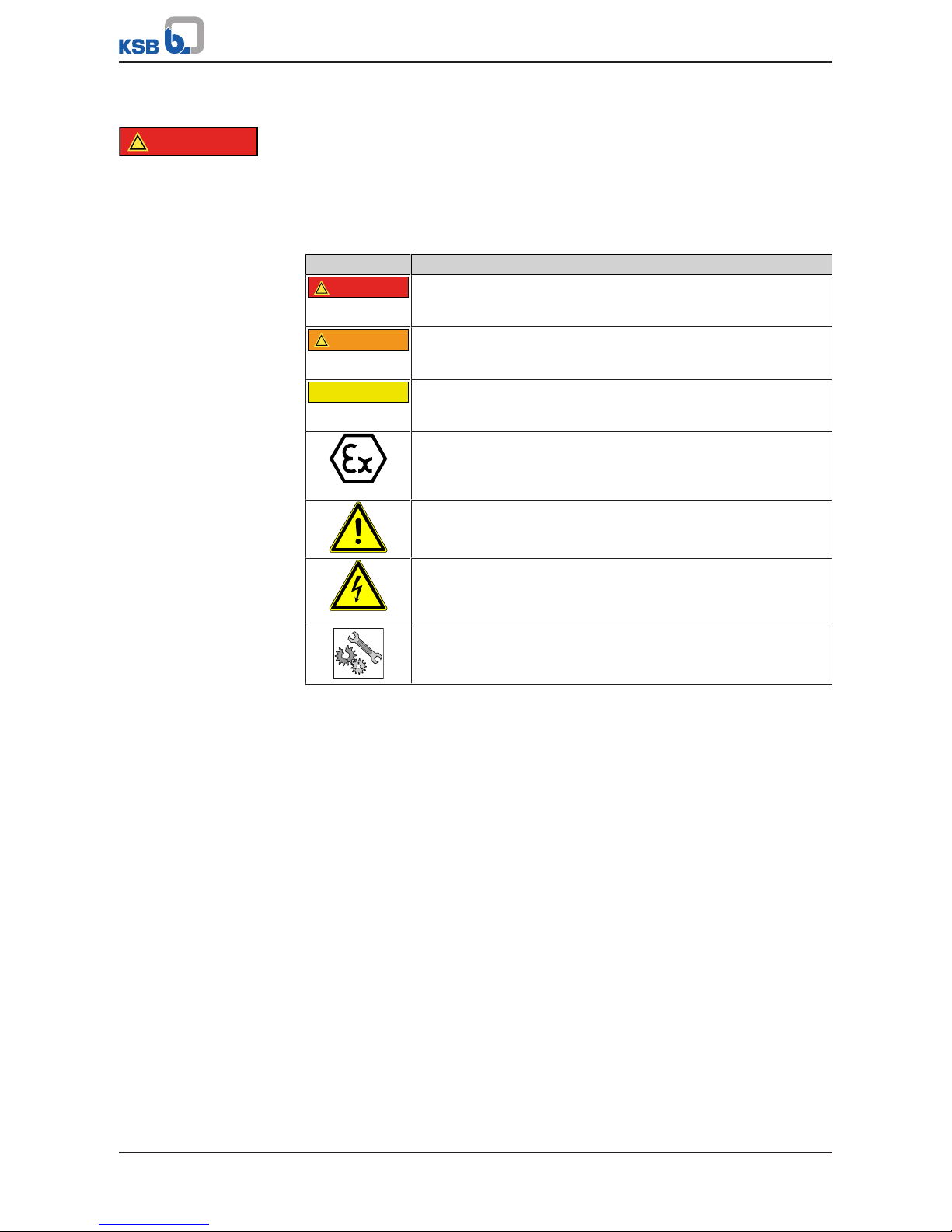
2 Safety
!
DANGER
All the information contained in this section refers to hazardous situations.
In addition to the present general safety information the action-related safety
information given in the other sections must be observed.
2.1 Key to safety symbols/markings
Table3: Definition of safety symbols/markings
Symbol Description
!
DANGER
DANGER
This signal word indicates a high-risk hazard which, if not avoided,
will result in death or serious injury.
!
WARNING
WARNING
This signal word indicates a medium-risk hazard which, if not
avoided, could result in death or serious injury.
CAUTION
CAUTION
This signal word indicates a hazard which, if not avoided, could
result in damage to the machine and its functions.
Explosion protection
This symbol identifies information about avoiding explosions in
potentially explosive atmospheres in accordance with EU Directive
2014/34/EU (ATEX).
General hazard
In conjunction with one of the signal words this symbol indicates a
hazard which will or could result in death or serious injury.
Electrical hazard
In conjunction with one of the signal words this symbol indicates a
hazard involving electrical voltage and identifies information about
protection against electrical voltage.
Machine damage
In conjunction with the signal word CAUTION this symbol indicates
a hazard for the machine and its functions.
2.2 General
This operating manual contains general installation, operating and maintenance
instructions that must be observed to ensure safe operation of the system and
prevent personal injury and damage to property.
The safety information in all sections of this manual must be complied with.
The operating manual must be read and understood by the responsible specialist
personnel/operators prior to installation and commissioning.
The contents of this operating manual must be available to the specialist personnel
at the site at all times.
Information attached directly to the product must always be complied with and kept
in a perfectly legible condition at all times. This applies to, for example:
▪ Arrow indicating the direction of rotation
▪ Markings for connections
▪ Name plate
The operator is responsible for ensuring compliance with all local regulations not
taken into account in this operating manual.

2 Safety
9 of 132
Amacan P
2.3 Intended use
▪ The pump (set) must only be operated in the fields of application and within the
use limits specified in the other applicable documents.
▪ Only operate pumps/pump sets which are in perfect technical condition.
▪ Do not operate the pump (set) in partially assembled condition.
▪ Only use the pump to handle the fluids described in the data sheet or product
literature of the pump model or variant.
▪ Never operate the pump without the fluid to be handled.
▪ Observe the limits for continuous duty specified in the data sheet or product
literature (Q
min
and Q
max
) (to prevent damage such as shaft fracture, bearing
failure, mechanical seal damage, etc).
▪ Observe the minimum flow rate and maximum flow rate indicated in the data
sheet or product literature (to prevent overheating, mechanical seal damage,
cavitation damage, bearing damage, etc).
▪ Always operate the pump (set) in the direction of rotation it is intended for.
2.4 Personnel qualification and training
All personnel involved must be fully qualified to transport, install, operate, maintain
and inspect the machinery this manual refers to.
The responsibilities, competence and supervision of all personnel involved in
transport, installation, operation, maintenance and inspection must be clearly
defined by the operator.
Deficits in knowledge must be rectified by means of training and instruction
provided by sufficiently trained specialist personnel. If required, the operator can
commission the manufacturer/supplier to train the personnel.
Training on the pump (set) must always be supervised by technical specialist
personnel.
2.5 Consequences and risks caused by non-compliance with this manual
▪ Non-compliance with these operating instructions will lead to forfeiture of
warranty cover and of any and all rights to claims for damages.
▪ Non-compliance can, for example, have the following consequences:
– Hazards to persons due to electrical, thermal, mechanical and chemical
effects and explosions
– Failure of important product functions
– Failure of prescribed maintenance and servicing practices
– Hazard to the environment due to leakage of hazardous substances
2.6 Safety awareness
In addition to the safety information contained in this manual and the intended use,
the following safety regulations shall be complied with:
▪ Accident prevention, health regulations and safety regulations
▪ Explosion protection regulations
▪ Safety regulations for handling hazardous substances
▪ Applicable standards, directives and laws
2.7 Safety information for the operator/user
▪ Fit protective equipment (e.g. contact guards) supplied by the operator for hot,
cold or moving parts, and check that the equipment functions properly.
▪ Do not remove any protective equipment (e.g. contact guards) during operation.
▪ Provide the personnel with protective equipment and make sure it is used.
2 Safety
10 of 132
Amacan P
▪ Contain leakages (e.g. at the shaft seal) of hazardous fluids handled (e.g.
explosive, toxic, hot) so as to avoid any danger to persons and the environment.
Adhere to all relevant laws.
▪ Eliminate all electrical hazards. (In this respect refer to the applicable national
safety regulations and/or regulations issued by the local energy supply
companies.)
▪ If shutting down the pump does not increase potential risk, fit an emergency-
stop control device in the immediate vicinity of the pump (set) during pump set
installation.
2.8 Safety information for maintenance, inspection and installation
▪ Modifications or alterations of the pump (set) are only permitted with the
manufacturer's prior consent.
▪ Use only original spare parts or parts/components authorised by the
manufacturer. The use of other parts/components can invalidate any liability of
the manufacturer for resulting damage.
▪ The operator ensures that maintenance, inspection and installation is performed
by authorised, qualified specialist personnel who are thoroughly familiar with
the manual.
▪ Only carry out work on the pump (set) during standstill of the pump.
▪ Only perform work on the pump set when it has been disconnected from the
power supply (de-energised).
▪ The pump (set) must have cooled down to ambient temperature.
▪ Pump pressure must have been released and the pump must have been drained.
▪ When taking the pump set out of service always adhere to the procedure
described in the manual. (ðSection6.3,Page47)
▪ Decontaminate pumps which handle fluids posing a health hazard.
▪ As soon as the work has been completed, re-install and re-activate any safety-
relevant devices and protective devices. Before returning the product to service,
observe all instructions on commissioning. (ðSection6.1,Page43)
2.9 Unauthorised modes of operation
Never operate the pump (set) outside the limits stated in the data sheet and in this
manual.
The warranty relating to the operating reliability and safety of the supplied pump
(set) is only valid if the equipment is used in accordance with its intended use.
2.10 Explosion protection
!
DANGER
Always observe the information on explosion protection given in this section when
operating an explosion-proof pump set.
Sections of the manual marked by the symbol opposite apply to explosion-proof
pump sets also when temporarily operated outside of potentially explosive
atmospheres.
Only pumps/pump sets marked as explosion-proof and identified as such in the data
sheet may be used in potentially explosive atmospheres.
Special conditions apply to the operation of an explosion-proof pump set to
EUDirective 2014/34/EU (ATEX).
Especially adhere to the sections in this manual marked with the symbol opposite.
The explosion-proof status of the pump set is only assured if the pump set is used in
accordance with its intended use.
Never operate the pump set outside the limits stated in the data sheet and on the
name plate.
Prevent impermissible modes of operation.

2 Safety
11 of 132
Amacan P
2.10.1 Repair
Special regulations apply to repair work on explosion-proof pumps. Modifications or
alterations of the pump set can affect explosion protection and are only permitted
after consultation with the manufacturer.
Repair work at the flameproof joints must only be performed in accordance with the
manufacturer's instructions. Repair to the values in tables 1 and 2 of EN60079-1 is
not permitted.

3 Transport/Temporary Storage/Disposal
12 of 132
Amacan P
3 Transport/Temporary Storage/Disposal
3.1 Checking the condition upon delivery
1. On transfer of goods, check each packaging unit for damage.
2. In the event of in-transit damage, assess the exact damage, document it and
notify KSB or the supplying dealer and the insurer about the damage in writing
immediately.
3.2 Transport
DANGER
Improper transport
Danger to life from falling parts!
Damage to the pump set!
▷ Use the attachment point provided for attaching the lifting accessory.
▷ Never suspend the pump set by its power cable.
▷ Use the lifting chain/rope included in the scope of supply exclusively for
lowering or lifting the pump set into/out of the pump sump.
▷ Securely attach the lifting chain/rope to the pump and crane.
▷ Use tested, marked and approved lifting accessories only.
▷ Observe the regional transport regulations.
▷ Observe the product literature supplied by the lifting accessory manufacturer.
▷ The load-carrying capacity of the lifting accessory must be higher than the
weight indicated on the name plate of the pump set to be lifted. Take into
account any additional system components to be lifted.
3.2.1 Transporting the delivered pump to the place of installation
Fig.1: Transporting the pump set in its original packaging
▪ The pump set is supplied in a horizontal position on a suitable transport support.
▪ Use suitable lifting equipment to transport the pump set in its original packaging
to its place of installation.
Observe the marked centres of gravity and/or attachment points on the transport
boxes!
For the weight refer to the name plate or data sheet. (ðSection4.3,Page18)
3.2.2 Placing the pump set in a vertical or horizontal position
WARNING
Pump set tilting
Risk of squashing hands and feet!
▷ Suspend or support the pump set.
3 Transport/Temporary Storage/Disposal
13 of 132
Amacan P
WARNING
Placing the pump set down on unsecured and uneven surfaces
Personal injury and damage to property!
▷ Always place down the pump set on a solid and level surface with the pump set
in a vertical position and the motor on top.
▷ Only place the pump set on a surface of sufficient load-carrying capacity.
▷ Use appropriate means to secure the pump set against tilting or tipping over.
▷ Refer to the weights given in the data sheet/on the name plate.
WARNING
Incorrect handling of the power cable
Personal injury and damage to property!
▷ Secure the power cables against falling down.
▷ Avoid power cables being laid on surfaces without fastening.
▷ When moving the pump set keep at a safe distance from the power cables.
WARNING
Improper handling when placing the pump set in a vertical/horizontal position
Personal injury and damage to property!
▷ Use one or two pieces of lifting equipment, depending on the pump size.
▷ Use appropriate means to secure the pump set against tilting, tipping over or
rolling off.
▷ Maintain a safe distance during lifting operations (load may swing when being
lifted).
▷ Use additional supports for the transport holder to secure it against tilting.
WARNING
Improper lifting/moving of heavy assemblies or components
Personal injury and damage to property!
▷ Use suitable transport devices, lifting equipment and lifting tackle to move
heavy assemblies or components.
CAUTION
Improper storage
Damage to the power cables!
▷ Support the power cables at the cable entry to prevent permanent
deformation.
▷ Only remove the protective caps from the power cables at the time of
installation.
3 Transport/Temporary Storage/Disposal
14 of 132
Amacan P
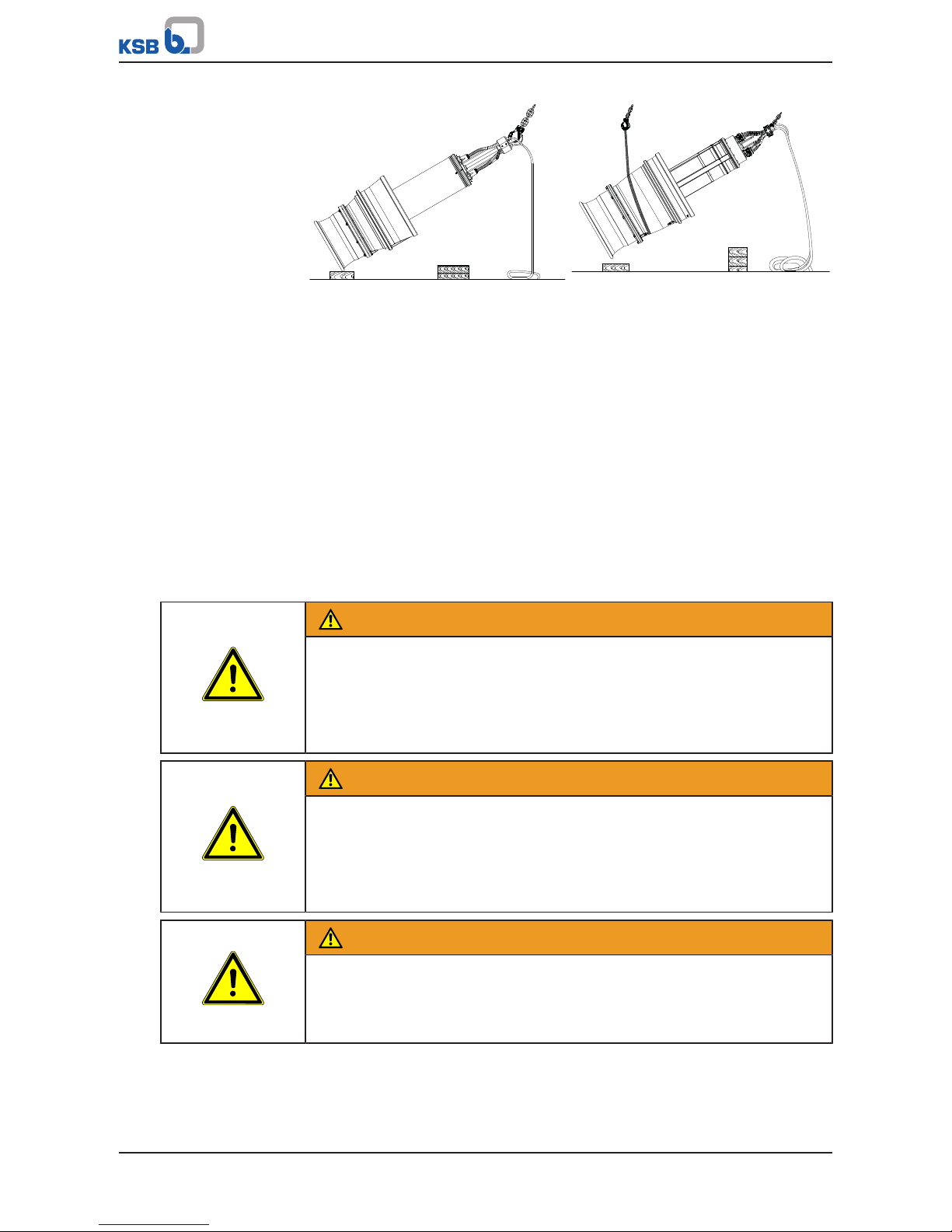
Pulling the pump set upright with one
crane
Pulling the pump set upright with two
cranes
ü Suitable lifting equipment has been selected (e.g. crane).
1. a) For one piece of lifting equipment: Attach the eyehook to the bail of the
pump set.
b) For two pieces of lifting equipment: Attach one eyehook to the bail of the
pump set. Then suitably loop a rope around the pump set and attach this loop
to the second crane hook.
2. Lift the pump set with the lifting equipment.
ð Guiding the pump set over the edge of the bellmouth or pump casing is only
permissible on a wooden base!
ð Protect the power cable against kinking!
3. Place the pump set on a level, clean surface and protect it against tilting, tipping
over or rolling off.
3.2.3 Transporting the pump set
WARNING
Incorrect positioning/placing down
Personal injury and damage to property!
▷ Position the pump set vertically with the motor on top.
▷ Use appropriate means to secure the pump set against tilting and tipping over.
▷ Refer to the weights given in the data sheet/on the name plate.
WARNING
Incorrect handling of the power cable
Personal injury and damage to property!
▷ Secure the power cables against falling down.
▷ Avoid power cables being laid on surfaces without fastening.
▷ When moving the pump set keep at a safe distance from the power cables.
WARNING
Improper lifting/moving of heavy assemblies or components
Personal injury and damage to property!
▷ Use suitable transport devices, lifting equipment and lifting tackle to move
heavy assemblies or components.
3 Transport/Temporary Storage/Disposal
15 of 132
Amacan P
WARNING
Improper handling when placing the pump set in a vertical/horizontal position
Personal injury and damage to property!
▷ Use one or two pieces of lifting equipment, depending on the pump size.
▷ Use appropriate means to secure the pump set against tilting, tipping over or
rolling off.
▷ Maintain a safe distance during lifting operations (load may swing when being
lifted).
▷ Use additional supports for the transport holder to secure it against tilting.
Fig.2: Transporting the pump set in a vertical position
Use suitable lifting equipment to transport the pump set in the illustrated position.
3.2.4 Transport lock
Pump sets from size Amacan P 1000 - 700 are supplied with a transport lock. Prior to
checking the direction of rotation, lowering the pump into the discharge tube and
commissioning, remove the transport lock, which is a metal plate between impeller
and bellmouth.
3.3 Storage/preservation
If commissioning is to take place some time after delivery, we recommend that the
following measures be taken:
Store the pump set as follows:
▪ In its original packaging: in a horizontal position
▪ Without packaging: in a vertical position with the motor on top
WARNING
Pump set tilting
Risk of squashing hands and feet!
▷ Suspend or support the pump set.
3 Transport/Temporary Storage/Disposal
16 of 132
Amacan P
CAUTION
Improper storage
Damage to the power cables!
▷ Support the power cables at the cable entry to prevent permanent
deformation.
▷ Only remove the protective caps from the power cables at the time of
installation.
CAUTION
Damage during storage due to humidity, dirt or vermin
Corrosion/contamination of the pump (set)!
▷ For outdoor storage cover the pump (set) or the packaged pump (set) and
accessories with waterproof material.
CAUTION
Wet, contaminated or damaged openings and connections
Leakage or damage to the pump!
▷ Clean and cover pump openings and connections as required prior to putting
the pump into storage.
Table4: Ambient conditions for storage
Ambient condition Value
Relative humidity 5% to 85% (non-condensing)
Ambient temperature -20°C to +70°C
▪ Store the pump set under dry and vibration-free conditions, if possible in its
original packaging.
1. Rotate the impeller by hand once every three months.
3.4 Return to supplier
1. Drain the pump as per operating instructions. (ðSection7.3.2,Page54)
2. Flush and clean the pump, particularly if it has been used for handling noxious,
explosive, hot or other hazardous fluids.
3. If the pump has handled fluids whose residues could lead to corrosion damage
in the presence of atmospheric humidity or could ignite upon contact with
oxygen also neutralise the pump and blow through with anhydrous inert gas to
ensure drying.
4. Always complete and enclose a certificate of decontamination when returning
the pump.
Indicate any safety measures and decontamination measures taken.
(ðSection11,Page127)
NOTE
If required, a blank certificate of decontamination can be downloaded from the
following web site: www.ksb.com/certificate_of_decontamination

3 Transport/Temporary Storage/Disposal
17 of 132
Amacan P
3.5 Disposal
WARNING
Fluids handled, consumables and supplies which are hot and/or pose a health
hazard
Hazard to persons and the environment!
▷ Collect and properly dispose of flushing fluid and any fluid residues.
▷ Wear safety clothing and a protective mask if required.
▷ Observe all legal regulations on the disposal of fluids posing a health hazard.
1. Dismantle the pump (set).
Collect greases and other lubricants during dismantling.
2. Separate and sort the pump materials, e.g. by:
- Metals
- Plastics
- Electronic waste
- Greases and other lubricants
3. Dispose of materials in accordance with local regulations or in another
controlled manner.
4 Description of the Pump (Set)
18 of 132
Amacan P
4 Description of the Pump (Set)
4.1 General description
▪ Submersible pump in discharge tube
Pump set for handling river water and stormwater, pre-screened domestic and
industrial waste water as well as activated sludge
4.2 Designation
Example: Amacan PA4 800-540 / 120 6UTG1
Table5: Designation key
Code Description
Amacan Type series
P Impeller type
P Propeller
A Pressure class
A
B
4 Number of vanes
800 Nominal diameter of the discharge tube [mm]
540 Nominal impeller diameter [mm]
120 Motor size
6 Number of motor poles
UT Motor version
UT Without explosion protection, standard
XT
Explosion protection II 2G Ex db h IIB T3 Gb
G1 Material variant
G1 Grey cast iron, standard material variant
G3 Grey cast iron with Zn anodes, shaft made of 1.4057 stainless steel
4.3 Name plate
a)
b)
TYPE
No.
Q
TEMP. MAX. °C kg
H
WARNING - DO NOT OPEN WHEN ENERGIZED
AVERTISSEMENT - NE PAS OUVRIR SOUS TENSION
MOTOR IP 68 SUBM. MAX. 30 m CLASS H
3 ~ M.-No.
V Hz cosφ
A IA/IN
kWP
2
WARNUNG - NICHT UNTER SPANNUNG ÖFFNEN
EN
DE
FR
min
-1
S1
5 m
40
1165
2018
970
149/86
4,7
0,87
400/690
50
123456
1
2
3
4
11
12
13
6
5
7
8
9
10
15
16
17
14
18
19
20
TYPE
No.
Q
TEMP. MAX. °C kg
H
WARNING - DO NOT OPEN WHEN ENERGIZED
AVERTISSEMENT - NE PAS OUVRIR SOUS TENSION
MOTOR IP 68 SUBM. MAX. 30 m CLASS H
3 ~ M.-No.
V Hz cosφ
A IA/IN
kWP
2
WARNUNG - NICHT UNTER SPANNUNG ÖFFNEN
EN
DE
FR
min
-1
S1
II 2G Ex db h IIB T3 Gb
0035 II 2G Ex db IIB T3 Gb
40
2018
21
9970918352/001010
4000 m3/h
80
R22L06-80
Amacan PA4 800-540/806 UTG1
Amacan PA4 800-540/806 XTG1
5 m
1165
970
149/86
4,7
0,87
400/690
50
123456
9970918352/001010
1600 m3/h
80
R22L06-80
22
IBExU08 ATEX 1064X
Johann-Klein-Straße 9
Deutschland
67227 Frankenthal
KSB SE & Co. KGaA
Johann-Klein-Straße 9
Deutschland
67227 Frankenthal
KSB SE & Co. KGaA
Fig.3: Name plate (example) a) Standard pump set b) Explosion-proof pump set
1 Designation 2 KSB order number
3 Flow rate 4 Maximum fluid temperature and ambient
temperature
5 Enclosure 6 Motor type
7 Rated power 8 Rated speed
9 Rated voltage 10 Rated current
11 Head 12 Year of construction
13 Total weight 14 Maximum submergence
15 Thermal class of winding insulation 16 Motor number
4 Description of the Pump (Set)
19 of 132
Amacan P
17 Power factor at rated operating point 18 Rated frequency
19 Duty cycle 20 Starting current ratio
21 ATEX marking for the submersible motor 22 ATEX marking for the pump set
4.4 Design details
Design
▪ Fully floodable submersible pump in discharge tube (submersible motor pump)
▪ Not self-priming
▪ Close-coupled design
▪ Single-stage
▪ Vertical installation
Drive
▪ Three-phase asynchronous squirrel-cage motor
▪ Type of protection Ex db IIB (motor integrated in explosion-proof pump set)
▪ Enclosure: IP68 to EN60529/IEC529
Shaft seal
▪ Two bi-directional mechanical seals in tandem arrangement, with liquid reservoir
▪ Leakage chamber
Impeller type
▪ Axial propeller in ECB design
Bearings
▪ Grease-lubricated rolling element bearings
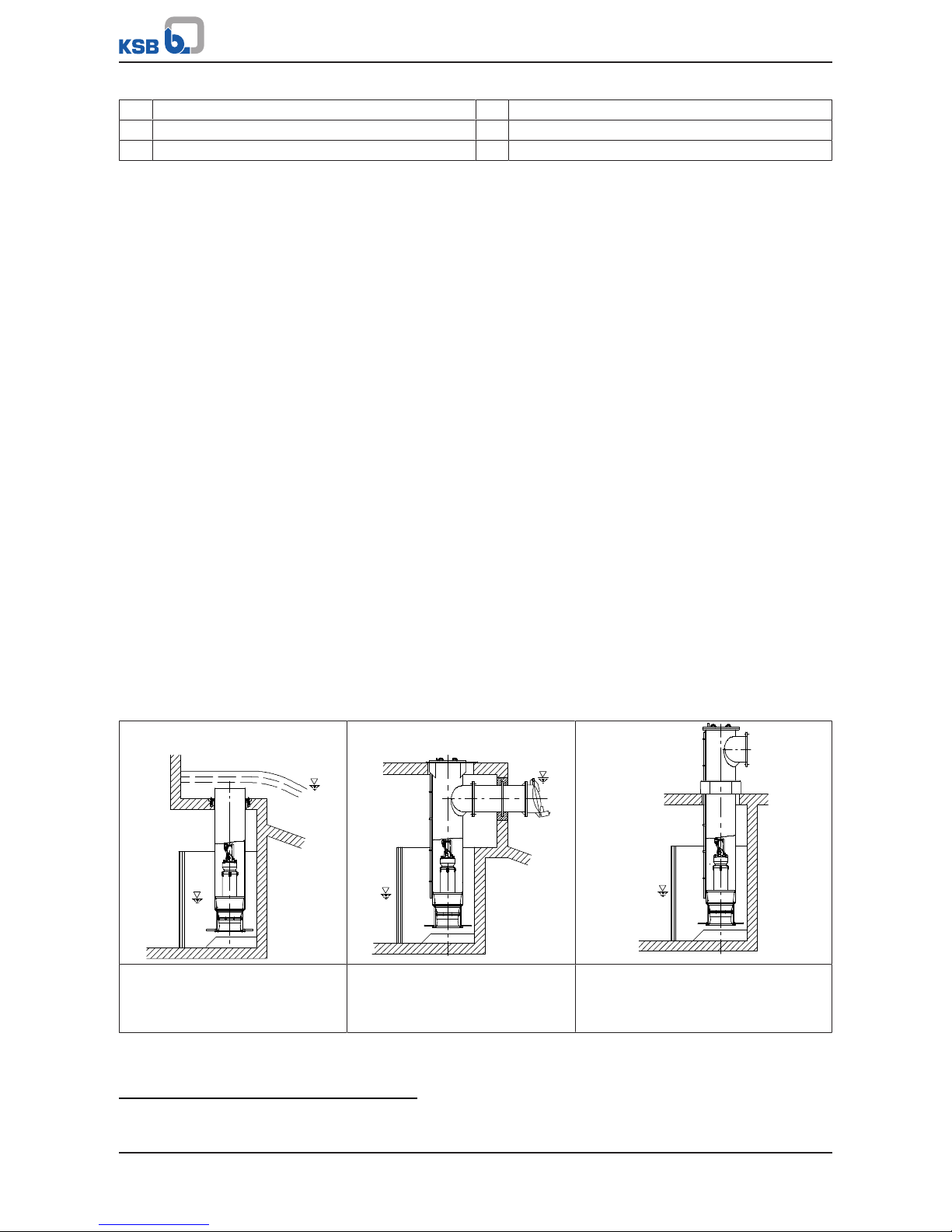
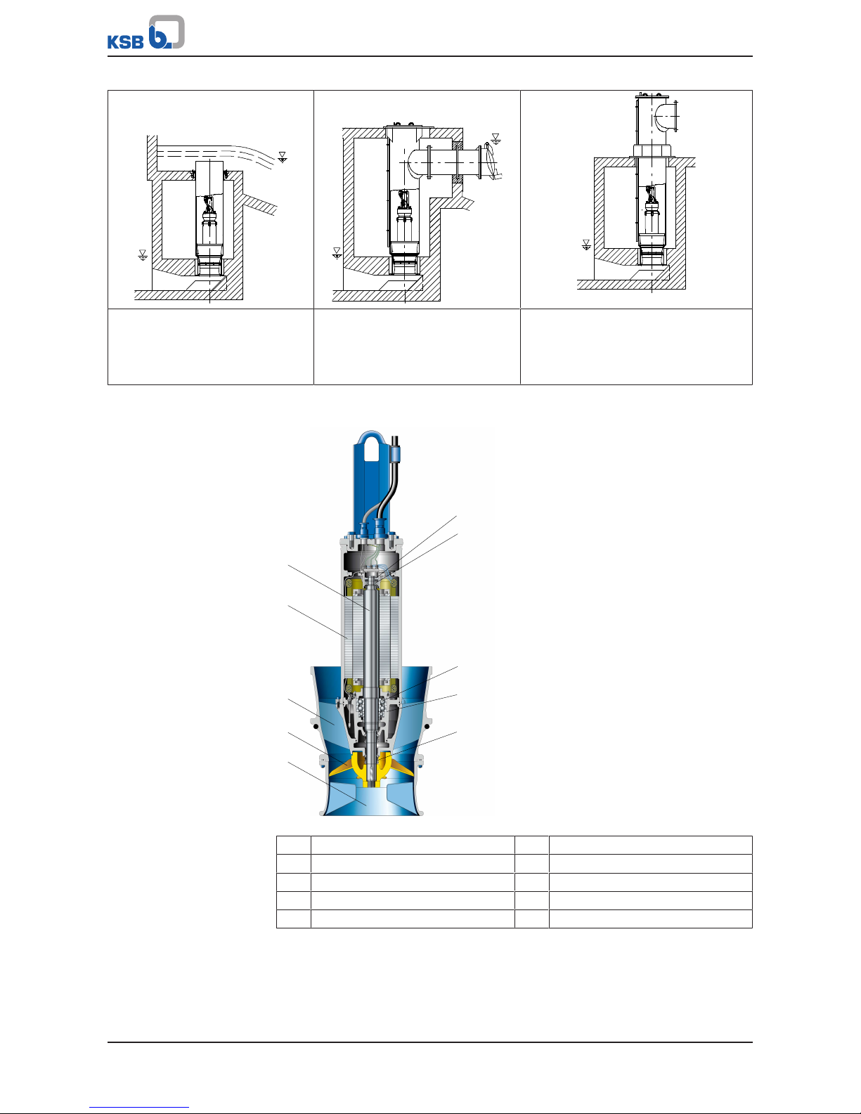
4.5 Installation types
Six different types are available for selection2):
Table6: Overview of installation types
BU discharge tube
Overflow design for installation in
open intake chamber
CU discharge tube
Design with underfloor discharge
for installation in open intake
chamber
DU discharge tube
Design with above floor discharge
nozzle for installation in open intake
chamber
2) For information on the various designs (foundation measurements, intake chamber, etc.) refer to the general arrangement
drawings.
4 Description of the Pump (Set)
20 of 132
Amacan P
BG discharge tube
Overflow design for installation in
covered intake chamber with low
suction-side water levels
CG discharge tube
Design with underfloor discharge
for installation in covered intake
chamber with low suction-side
water levels
DG discharge tube
Design with above-floor discharge
nozzle for installation in covered intake
chamber with low suction-side water
levels
4.6 Configuration and function
1
2
3
4
5
6
7
8
9
10
Fig.4: Amacan with axial propeller
1 Suction nozzle (bellmouth) 2 Impeller
3 Pump bowl 4 Electric motor
5 Shaft 6 Bearing, motor end
7 Bearing bracket 8 Bearing, pump end
9 Bearing housing, pump end 10 Shaft seal
Design The pump is designed with an axial fluid inlet and an axial outlet. The hydraulic
system sits on the extended motor shaft. The shaft runs in common bearings.
Function The fluid enters the pump axially via a suction nozzle (bellmouth) (1) and is
accelerated outward in a rotating flow by the rotating impeller (2). The required
energy is transmitted from the electric motor (4) to the impeller (2) via the shaft (5).
In the pump bowl (3) the kinetic energy of the fluid is converted into pressure energy
4 Description of the Pump (Set)
21 of 132
Amacan P
and the rotational movement of the fluid flow is diverted in axial direction. The shaft
passage through the casing is sealed towards the fluid with a shaft seal (10). The
shaft (5) runs in two rolling element bearings (6 and 8), which are supported by the
bearing housing (9) and the bearing bracket (7).
Sealing The pump is sealed by two bi-directional mechanical seals in tandem arrangement.
A lubricant reservoir in-between the seals ensures cooling and lubrication of the
mechanical seals.
Monitoring
equipment
The pump sets are equipped with various sensors.
Standard
▪ Temperature monitoring of the motor
▪ Temperature monitoring at the lower bearing
▪ Leakage monitoring of mechanical seals
▪ Leakage sensors in the motor chamber and connection space
Option
▪ Temperature monitoring at the upper bearing
3)
▪ Vibration sensor
▪ Additional winding temperature monitoring with Pt100 resistance thermometer
4.7 Scope of supply
Depending on the model, the following items are included in the scope of supply:
▪ Pump set complete with power cables
▪ O-ring
▪ Back-up name plate
Optional accessories:
▪ Support rope
▪ Accessories for installing the cable guide:
– Fitting
– Turnbuckle
– Support
– Shackle
– Cable clamps
▪ Cable support sleeves
▪ Discharge tube
▪ Flow-straightening vane to prevent floor vortices
NOTE
A separate name plate is included in KSB's scope of supply.
This name plate must be attached in a clearly visible position outside the place of
installation, e.g. at the control panel, pipeline or mounting bracket.
4.8 Dimensions and weights
For dimensions and weights refer to the name plate or data sheet of the pump set.
3) Included in the standard design for size 1600-1060
5 Installation at Site
22 of 132
Amacan P
5 Installation at Site
5.1 Safety regulations
DANGER
Improper installation in potentially explosive atmospheres
Explosion hazard!
Damage to the pump set!
▷ Comply with the applicable local explosion protection regulations.
▷ Observe the information in the data sheet and on the name plates of pump and
motor.
DANGER
Persons in the intake chamber during pump set operation
Electric shock! Risk of injury!
▷ Never start up the pump set when there are persons in the intake chamber.
WARNING
Impermissible solid objects (tools, screws/bolts or similar) in the pump sump/inlet
tank during pump start-up
Personal injury and damage to property!
▷ Check the pump sump/inlet tank for impermissible solid objects before
flooding, and remove, if necessary.
5.2 Checks to be carried out prior to installation
5.2.1 Checking the structural requirements
All structural work required must have been prepared in accordance with the
dimensions stated in the outline drawing/general arrangement drawing.
5.2.2 Checking the operating data
Before inserting the pump set into the discharge tube, verify the data on the name
plate against the data given in the purchase order and the system data.
Back-up name plate KSB’s scope of supply includes a separate name plate attached to the end of the
pump cable which indicates the pump and motor data.
1. Attach this name plate in a clearly visible position outside the discharge tube,
e.g. at the control cabinet, pipeline or mounting bracket.
5.2.3 Checking the lubricant of the mechanical seal
The lubricant reservoir is filled at the factory with an environmentally-friendly, nontoxic lubricant.
The pump set is supplied in a horizontal position on a suitable transport support.
Visual inspection for signs
of oil leakage
1. If no oil leakage is visible in the area of pump bowl, impeller or transport
support, the lubricant reservoir is filled properly.
2. If oil leakage is visible in the area of pump bowl, impeller or transport support,
top up the lubricant.
5 Installation at Site
23 of 132
Amacan P
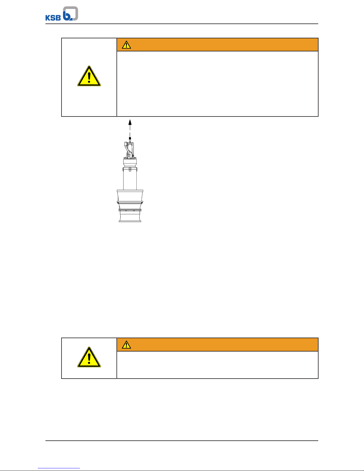
903.03
903.01
411.01
FD
Fig.5: Checking the lubricant level
Table7: Key to the symbols and codes
Symbol Description
FD
Always apply a liquid sealant (e.g. Hylomar SQ32M) to sealing surfaces
marked with this symbol.
1. Place the pump set down in a horizontal position and make sure it cannot roll
off. (ðSection3.2.2,Page12)
2. When placing the pump set down, make sure that screw plug 903.03 is on top.
3. Remove screw plug 903.03.
4. Remove screw plug 903.01 and joint ring 411.01.
5. Shine a torch through the hole in the pump bowl to see the opening of the
lubricant reservoir.
ð If the lubricant level reaches the opening, fit screw plug 903.01 together with
a new joint ring 411.01, and screw plug 903.03.
ð If the lubricant level is below the opening, top up the lubricant.
(ðSection7.4.1.4.2,Page58)
6. Re-insert and tighten screw plug 903.01 with joint ring.
7. Re-insert and tighten screw plug 903.03.
NOTE
If more than 1.5 litres of lubricant are required for topping up, this suggests a
defect of the mechanical seals.
5.2.4 Checking the direction of rotation
DANGER
Pump set running dry
Explosion hazard!
▷ Check the direction of rotation of explosion-proof pump sets outside
potentially explosive atmospheres.
5 Installation at Site
24 of 132
Amacan P
WARNING
Improper handling when placing the pump set in a vertical/horizontal position
Personal injury and damage to property!
▷ Use one or two pieces of lifting equipment, depending on the pump size.
▷ Use appropriate means to secure the pump set against tilting, tipping over or
rolling off.
▷ Maintain a safe distance during lifting operations (load may swing when being
lifted).
▷ Use additional supports for the transport holder to secure it against tilting.
WARNING
Improper positioning of pump set when checking the direction of rotation
Personal injury and damage to property!
▷ Use appropriate means to secure the pump set against tilting or tipping over.
WARNING
Hands and/or foreign objects in the pump casing
Risk of injuries, damage to the pump!
▷ Never insert your hands or any other objects into the pump.
▷ Check that the inside of the pump is free from any foreign objects.
▷ Verify that the transport lock has been removed.
▷ Take suitable precautions (e.g. wear safety goggles).
CAUTION
Pump set running dry
Increased vibrations!
Damage to mechanical seals and bearings!
▷ Never operate the pump set for more than 60seconds outside the fluid to be
handled.
Check the direction of rotation before installing the pump set, i.e. in dry condition.
1. Place the pump set in a vertical position on a level surface and secure it
sufficiently against tipping over. (ðSection3.2.2,Page12)
2. Connect the pump set to the power supply and start it up.
3. Use one of the following options to check the direction of rotation:
ð 1. Look down into the pump bowl and check that the impeller is turning
clockwise.
ð 2. Verify the direction of rotation of the impeller against the arrow
indicating the direction of rotation on the pump bowl.
4. If the impeller rotates in the wrong direction of rotation, check and correct the
electrical connection and the control system if applicable. Then check the
direction of rotation again.
5. If the direction of rotation is correct, mark which core ends match which of the
terminals in the control cabinet.
6. Disconnect the pump set from the power supply and secure it against
unintentional start-up.
5 Installation at Site
25 of 132
Amacan P
WARNING
Unintentional starting of the pump set
Risk of injury by moving components and shock currents!
▷ Ensure that the pump set cannot be started unintentionally.
▷ Always make sure the electrical connections are disconnected before carrying
out work on the pump set.
5.3 Lowering the pump set into the discharge tube
DANGER
Improper transport
Danger to life from falling parts!
Damage to the pump set!
▷ Use the attachment point provided for attaching the lifting accessory.
▷ Never suspend the pump set by its power cable.
▷ Use the lifting chain/rope included in the scope of supply exclusively for
lowering or lifting the pump set into/out of the pump sump.
▷ Securely attach the lifting chain/rope to the pump and crane.
▷ Use tested, marked and approved lifting accessories only.
▷ Observe the regional transport regulations.
▷ Observe the product literature supplied by the lifting accessory manufacturer.
▷ The load-carrying capacity of the lifting accessory must be higher than the
weight indicated on the name plate of the pump set to be lifted. Take into
account any additional system components to be lifted.
DANGER
Improper installation in potentially explosive atmospheres
Explosion hazard!
Damage to the pump set!
▷ Comply with the applicable local explosion protection regulations.
▷ Observe the information in the data sheet and on the name plates of pump and
motor.
WARNING
Incorrect handling of the power cable
Personal injury and damage to property!
▷ Secure the power cables against falling down.
▷ Avoid power cables being laid on surfaces without fastening.
▷ When moving the pump set keep at a safe distance from the power cables.
WARNING
People falling into the unsecured discharge tube
Risk of personal injury!
▷ Take suitable precautions during the entire installation/removal process to
protect people from falling into the open discharge tube.
▷ Fence off the work area appropriately.

5 Installation at Site
26 of 132
Amacan P
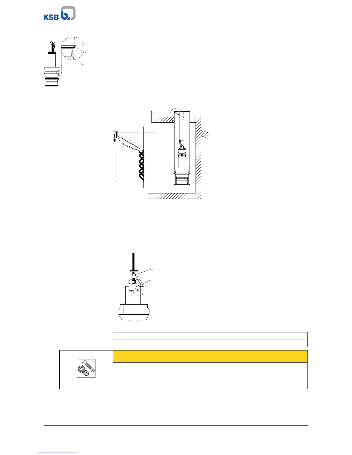
5.3.1 Information for correct installation
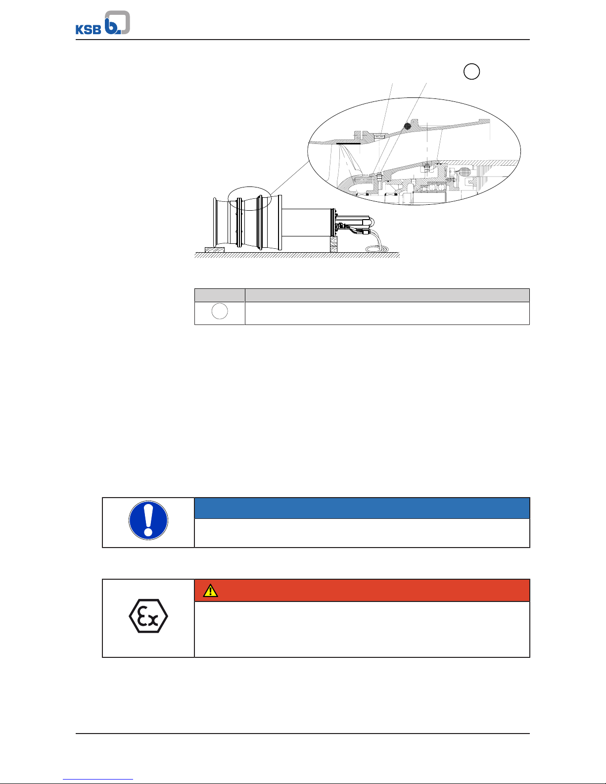
The flow-straightening vane is indispensable for the inlet conditions of the pump
set. It prevents the development of a submerged vortex (floor vortex) which could
cause a drop in performance, for example. To provide optimum inlet conditions,
observe the following information:
1. Observe the structural requirements!
Install the flow-straightening vane concentrically below the discharge tube, see
general arrangement drawing.
1
2
3
Fig.6: Installation position of the flow-straightening vane
1 Flow-straightening vane 2 Discharge tube
3 Intake chamber
2. Observe the installation position of the pump set!
Lower the pump set into the discharge tube with the anti-swirl baffles (2) in the
bellmouth aligned with the flow-straightening vane (3).
Use the bail alignment of the pump set for orientation. The bail (1) is aligned
with the anti-swirl baffles (2).
1
2
3
Fig.7: Installation position of the pump set
1 Bail 2 Anti-swirl baffles
3 Flow-straightening vane
5.3.2 Installation without support rope
CAUTION
Incorrect installation
Damage to the pump set!
▷ Verify that the pump set is correctly seated in the discharge tube.
5 Installation at Site
27 of 132
Amacan P
412.05
112
Fig.8: Inserting the O-ring
Refer to and comply with the general arrangement drawing/outline drawing when
installing the pump set.
1. If not already fitted, insert the supplied O-ring 412.05 into pump bowl 112.
2. Attach the crane hook to the bail of the pump set.
3. Centre the pump set above the discharge tube. Slowly lower the pump set into
the discharge tube until it is seated in the recommended position.
(ðSection5.3.1,Page26)
4. Pull the electric cables up by hand. Fasten them to the sump construction with a
cable support sleeve if required. Do not lift the pump set out of its seat.
X
X
Fig.9: Fastening the cable support sleeve
5.3.3 Installation with a support rope
Refer to and comply with the general arrangement drawing/outline drawing when
installing the pump set.
Prior to installing the pump set, visually inspect the support rope. Do not exceed the
permissible load-carrying capacity.
X
59-24
X
59-17.01
Fig.10: X = indication of load-carrying capacity
59-24 Support rope
59-17.01 Shackle
CAUTION
Incorrect installation
Damage to the pump set!
▷ Verify that the pump set is correctly seated in the discharge tube.
5 Installation at Site
28 of 132
Amacan P
WARNING
Pump set drops during the installation or removal process
Personal injury and damage to property!
▷ Never use the turnbuckle , shackle or discharge tube cover to lift the pump set.
▷ Always use lifting lug 59-47.
NOTE
Prior to fitting the turnbuckle, check that the corresponding split pin has not been
cracked and/or chipped. If damaged, always use a new split pin.
ü Suitably sized lifting equipment is available.
ü The support rope has been visually inspected.
ü The split pin of the turnbuckle has been checked for any damage.
412.05
112
Fig.11: Inserting the O-ring
1. If not already fitted, insert the supplied O-ring 412.05 into pump bowl 112.
1
2
3
4
5
6
Fig.12: Lifting and positioning the pump set
2. Secure the lifting chain or lifting rope (1) to the trolley (4) of the lifting
equipment (2).
3. Attach the support rope (5) to the bail by its shackle. (ðSection9.2,Page94)
For a galvanised shackle, secure the pin at the shackle with Loctite243.
For a stainless steel shackle, undo and tighten the pin twice and secure it with
Loctite243.
4. Check that the support rope is arranged correctly.
ð The free lifting lug (6) has to point away from the pump set
5. Partially unwind the support rope and electric cables.
6. Lower the pump set into the discharge tube until the bail is in an accessible
position, protruding from the discharge tube.
7. Securely cover the discharge tube except for a gap which allows work to
continue.
5 Installation at Site
29 of 132
Amacan P
8. Attach the first lifting lug of the support rope (5) to the lifting rope (1) to
securely position the pump set above the discharge tube.
9. Unclip the hook of the lifting equipment from the lifting lug of the support
rope and run the lifting equipment to a higher level.
8
7
9
Fig.13: Securing the control cable and power cable
10. Secure the control cable (7) and power cables (8) to the crane hook (3) of the
lifting equipment with a manila rope (9).
11. Trim spacer (a) to fit between the two ferrules.
a
b
c
d
e
f
Fig.14: Cross-section of the cable guide
12. Insert the support rope (f) and the control cable (c) into the spacer (a) and make
sure that they are in their respective ducts.
13. Tighten the electric cables with the manila rope running over the crane hook.
14. Insert the power cables (b) into the hollows of the spacer (a) and, starting from
the bottom, firmly clamp the power cables with cable clamps (d) covered by a
plastic sheath (e).
15. In the area of the lifting lug between the rope sections, lay all electric cables in
loops and fasten them to the rope section above.
16. Progressively lower the pump set into the discharge tube while securing the
cable bundle with evenly spaced sheathed cable clamps.
17. Fit a heat shrink tube on any protruding sharp-edged rope ends (e.g. at the
ferrule) to prevent any damage to the power cable and control cable.
5 Installation at Site
30 of 132
Amacan P
Fig.15: Lowering the pump set
18. Finally, attach the support rope with shackle and turnbuckle to a suspension
loop (provided in the discharge tube or structure). Secure the turnbuckle with a
split pin. After inserting the split pin, bend over its two legs.
19. Tighten the turnbuckle until the cable bundle is tight without lifting the pump
off its seat.
20. Unclip the hook of the lifting equipment from the lifting lug, free the electric
cables from the manila rope and route them to the control cabinet.
21. Make sure that the top loose lifting lug is attached to the cable bundle to
prevent noise and wear caused by chafing.
22. Remove the safety cover from the discharge tube and mount the discharge tube
cover. Seal the cable entries if any!
5.3.4 Installation with a support rope and support spacer
Always refer to and comply with the general arrangement drawing/ outline drawing
when installing the pump set.
Prior to installing the pump set, visually inspect the support rope. Do not exceed the
permissible load-carrying capacity.
X
59-24
X
59-17.01
Fig.16: X = indication of load-carrying capacity
59-24 Support rope
59-17.01 Shackle
 Loading...