

Krushr K024 Installation Manual

US/Can
Waste Recycling Compactor
Installation Manual
Compacteur de déchet pour le recyclage
Manuel d'installation
Models: / Modèles :
F86/024, F86/021, F86/018, F86/015, F86/012
Krushr plc
www.krushr.com
Custom made Krushr bags available from your local dealer or www.krushr.com
Des sacs sur-mesure krushr sont disponibles chez votre revendeur local ou sur www.krushr.com
A34/052-R1 March 2015

US/Can
Index
Please read all safety information before you operate this appliance
Safety Symbols .......................................................................................................... 3
Safety & Pre-Installation Information ....................................................................... 4
Parts Supplied............................................................................................................ 4
Tools Required .......................................................................................................... 5
Design Information .................................................................................................... 5
Product Dimensions and Clearances ......................................................................... 5
Grounding Instructions and Electrical Safety ............................................................ 7
Installation Instructions............................................................................................. 8
Unpacking .................................................................................................................. 8
Positioning the appliance – Important Considerations ............................................. 8
Door installation ...................................................................................................... 11
How to anchor the appliance .................................................................................. 16
Door Mounting Guide ............................................................................................. 17
2
US/Can
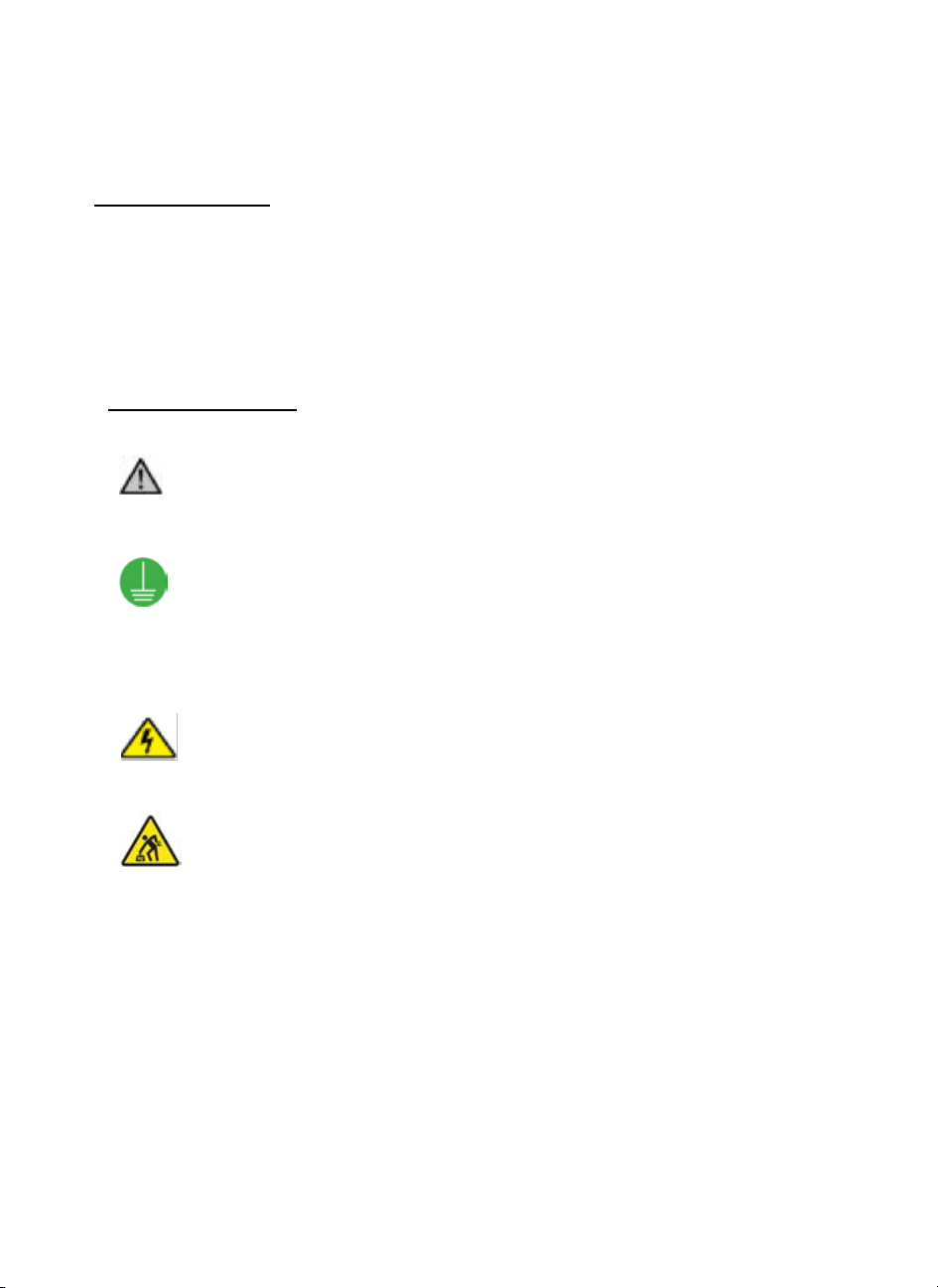
Warning/Caution
An appropriate safety instruction should be followed or
caution to a potential hazard exists
Protective Earth/Ground
To identify any terminal which is intended for
connection to an external conductor for protection
against electric shock in case of a fault or the terminal
of a protective earth (ground) electrode
Dangerous Voltage
To indicate hazards arising from dangerous voltages
Heavy
This product is over 40 lbs (18 kg). Reference should be
made to the safety instructions for provision for lifting
and moving.
Electrical rating 120V, 60Hz, 270W
Safety Symbols
PLEASE READ BEFORE YOU COMMENCE INSTALLATION
Save these instructions
The following safety symbols are used upon your Krüshr appliance and supporting
documentation
Meaning/Description
3
US/Can
Safety & Pre-Installation Information
PLEASE READ BEFORE YOU COMMENCE INSTALLATION
IMPORTANT – TO THE INSTALLER
Keep a copy of these instructions somewhere safe
Leave a copy of these instructions for the consumer
Installation of this appliance requires basic mechanical and
electrical skills
Installation time – approximately 30 minutes
Proper installation is the responsibility of the installer
Product failure due to incorrect product installation is not
covered under the warranty. See owners User Guide
IMPORTANT – TO THE CONSUMER/OWNER
Keep these instructions with your User Guide for future reference
This product is for domestic use only
This product is suitable for built-in/integrated installations ONLY
Parts Supplied
Hook Plate - To affix door
Mounting Plate - To secure door from beneath
Anchoring Plate - Floor anchor for free standing appliance
Rigidity brackets – To secure the door securely to the top of the cage
4
US/Can
Tools Required
For leg adjustment - Legs are adjusted by hand – no tools required
To fix/anchor appliance to sides - Appropriate screws (NOT supplied);
screwdriver
To fix/anchor appliance to floor - Appropriate floor fixing bolts or screws (NOT
supplied); screwdriver
To fit door
Furniture door - Screws (screws NOT supplied); screwdriver
Stainless Steel Door - Adjustable spanner; cross head screwdriver
IMPORTANT
To ensure that no damage is caused to surrounding cabinetry ensure that you
source appropriate sized screws/fixing bolts that are no longer than the
thickness of your door.
Design Information
Electrical Supply Requirements
The Krüshr appliance requires 120V, 60Hz, 270W supplied from an appropriate
Branch circuit protected source. The Krüshr appliance is provided with a NEMA
5-15 Grounded connector
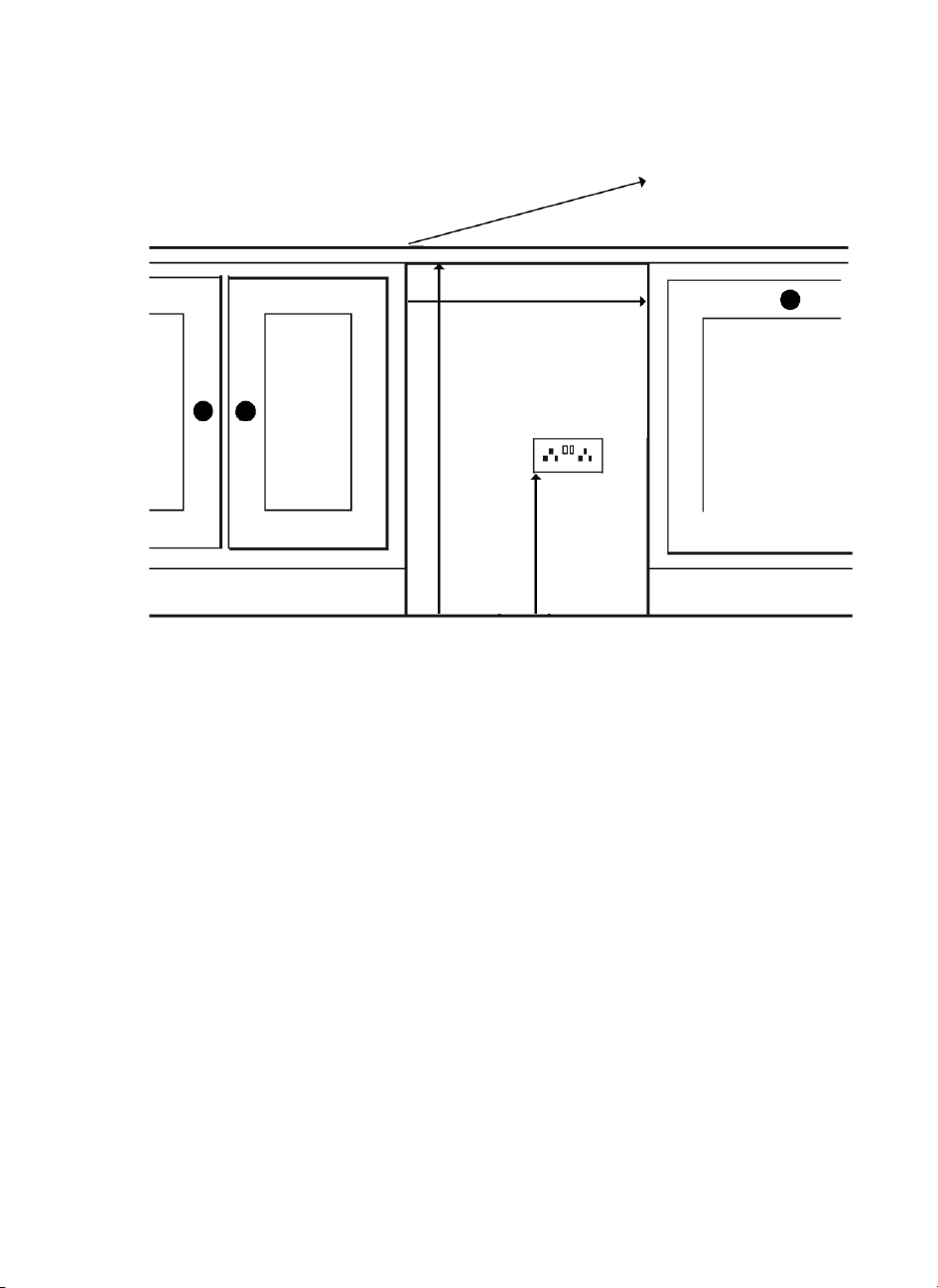
Product Dimensions and Clearances
To install the appliance, you will require the following under-counter space:
WIDTH
A minimum opening width of 24” for Model F86/024, 21” for Model F86/021,
18” for Model F86/018, 15” for Model F86/015 and 12” for Model F86/012.
HEIGHT
A minimum opening height of 32 1/4”
DEPTH
A minimum opening depth for all Models (without door) of 22 1/8”. Ensure
you have enough additional depth to accommodate the thickness of the door
being fitted.
5
US/Can
DEPTH
WIDTH
MIN. OPENING HEIGHT
MIN HEIGHT
SOCKET
Allow for extra space in the depth to accommodate the plug and socket
connection point. The plug socket should be at least 17 3/8” from the ground.
The appliance is equipped with a power cord. An electrical outlet must be
provided in the under-counter opening that meets all applicable electrical
codes and requirements. See “Grounding Instructions” for specific electrical
installation details.
Under no circumstances should the appliance be operated without a main
door fitted. The main door protects the operator from the mechanism during
operation.
6
Grounding Instructions and Electrical Safety
Grounding Instructions
This appliance must be grounded to a metal permanent wiring system, or an
equipment grounding conductor must be run with the circuit conductors and
connected to the equipment grounding terminal or lead on the appliance. See
the installation instructions for information on electrical requirements or seek
the advice of a qualified electrician.
Electric shock could result if the electrical supply for the appliance covered in
this Installation Manual is incorrectly installed or if the appliance has been
improperly grounded. Do not use the appliance if you are not certain the
electrical supply has been correctly installed or the appliance has been
properly grounded.
The appliance is equipped with a three-conductor cord and three-prong
grounding type plug to fit the proper grounding type receptacle. The green –
or green and yellow – coloured conductor in the cord is the grounding wire.
Never connect the green – or green and yellow – wire to a live terminal.
US/Can
IMPORTANT
If the supply cord is damaged, the cord must be replaced by the manufacturer,
its service agent or similarly qualified person in order to avoid a hazard.
WARNING – READ THESE INSTRUCTIONS THOROUGHLY BEFORE
CONNECTING THIS PRODUCT TO THE MAINS SUPPLY
Electrical Safety
Before switching on make sure that the voltage of your electricity supply is the
same as that indicated on the rating place. This appliance is for use on a
nominal 120 volt circuit.
This appliance is fitted with a non-rewireable plug. Should the supply cord
become damaged it should be replaced by a qualified service technician.
7
US/Can
Unplug the appliance from outlet before servicing
Do not modify the plug attached to the appliance
Use only with a grounded receptacle
When not in use or uninstalled the appliance should be kept in a clean, cool
and dry environment and with the main door firmly closed. The power cord
must be kept away from any heat source and sharp instruments.
Installation Instructions
Unpacking
IMPORTANT - Provisions for lifting and carrying should be made as this
product weighs over 40 lbs (18 kg)
Remove the appliance from its packaging.
Positioning the appliance – Important Considerations
Securing the appliance in a standalone installation
The floor anchor (shown in dia. 8) should be fitted when the appliance is used
in a standalone installation where no surrounding cabinetry is available to fix
the appliance in position. The floor anchor is used to secure the rear feet to
the floor to avoid the appliance tipping forward when the door is fully opened.
When using the floor anchor in a standalone situation, the appliance can only
be installed with the legs fully retracted. To attach the floor anchor to the
appliance, first extend the rear legs by approximately 0.6”. Slide the legs into
the floor anchor. Once in position, retract the legs fully. This locks the floor
anchor to the appliance. To remove, reverse these instructions.
8

US/Can
Leg Adjustment
Ensure that you have the appropriate size under-counter space prior to
installation. Please see “Product Dimensions and Clearances” on page 5 for further
details.
Slide the appliance next to the designated under-counter space and measure the
distance that the legs will need to be adjusted in order to elevate the appliance to
the correct height for your worktop/counter.
To reduce or increase the leg height, simply loosen and spin the leg. Adjust the
legs to just short of the proposed height so that the appliance will slot into the
allocated space easily. You might want to consider using a lever under the
appliance to lift it up, or a G-clamp to hold the top of the appliance under the
worktop/carcass. Plug the appliance into the electrical socket (switched on) and
slide it into the space.
Door allowance
MOST IMPORTANT - When positioning the appliance into the space it is
imperative to make appropriate allowance for the thickness of the door. The front
fascia of the appliance must not be set too far back. Any gap between the front
fascia of the appliance and the closed door will prevent the safety micro switches
from connecting preventing operation of the appliance. Ensure the appliance is set
far enough forward within the under-counter space so that the door shuts tight
against the appliance front fascia and also flush with any surrounding cabinetry.
Ensure that you test the micro switches once you have fitted the door and BEFORE
you permanently anchor the appliance. To test the micro switches open and close
both the main door (with Main Collection Bin cage attached) and Can Collection
Drawer (Models F86/024, F86/021, F86/018) listening carefully for a double click
of the micro switches when you close the door/drawer.
9

US/Can
Worktop clearance for removal of the Main Collection Bin
During installation of the appliance you will need to assess the ease by which the
Main Collection Bin can be removed. This is particularly relevant where a work
surface (including any grab rail attached to the work surface) overhangs the
appliance. The closer the top of the appliance to the work surface, the more acute
the angle is in order to remove the Main Collection Bin. To avoid problems in
removal of the Bin and or its contents, it is recommended that the work surface
(including any grab rail) does not overhang by more than 0.8”.
10

Step 1
Krüshr stainless
steel doors are
supplied with
predrilled holes.
For other
furniture doors
you are required
to drill the screw
holes into the
door according to
the position as
illustrated in Dia.
A detailed hole
position template
can be found in
“Door Mounting
Guide” on
page 17.
2 X Handle mount holes
(S model only)
4 x Door mount holes
(not ‘through’ holes)
2 x Base mount holes
(not ‘through’ holes)
Dia.1
Door installation
US/Can
WARNING
Take great care NOT to drill right through the door. All models will accommodate
either a Krüshr stainless steel door or other furniture door. For furniture doors
with panels it would be advisable to add an additional wood panel to the rear of
the door to provide additional strength.
11
 Loading...