

Krystal Pure KS10 Owner's Manual
10/12 KPWS • 44
Includes: Specications, Installation and Service Instructions,and Troubleshooting Guidelines
Incluye: Especicaciones, Instalación e Instrucciones de mantenimiento, y Guía de resolución de problemas
For Water Softener/Conditioner Systems
Para sistemas suavizantes/acondicionadores de agua
KS5 • KS10 • KS15HE
Owners Manual
Manual del propietario
KS Softeners Certied by WQA
to NSF/ANSI 44 for the reduc-
tion of Hardness, as veried and
substantiated by Test Data.
Suavizantes KS Certicado por WQA a NSF/ANSI
44 para la reduccion de la dureza, como verica-
do y sustentado en datos de prueba.

1 • 10/12 KPWS
Introduction.............................................................................................................................................. 3
Benefits of Soft/Conditioned Water..................................................................................................... 3
Warnings.................................................................................................................................................... 3
Specifications & Limitations................................................................................................................. 5
Installation Inspection............................................................................................................................ 5
Installation Procedures.......................................................................................................................... 7
Connect to Water Supply................................................................................................................... 7
Connect to Drain................................................................................................................................ 9
Connect Brine Line............................................................................................................................ 9
System Start-Up............................................................................................................................... 11
Schematic of Figure 1: KS5 & KS10 Controller..................................................................... 11
Schematic of Figure 2: KS15HE Controller........................................................................... 13
Connect Electrical............................................................................................................................ 13
Program the Valve Control.............................................................................................................. 13
Factory Default Settings......................................................................................................... 17
Use & Care............................................................................................................................................... 17
Sodium added to Water from Cation Exchange Softening........................................................... 19
KS15HE Schematic of Valve & Parts.................................................................................................. 21
KS15HE Parts List........................................................................................................................... 23
KS15HE Contents & Schematics........................................................................................................ 23
KS15HE Contents Parts List........................................................................................................... 23
Schematic of Valve & Parts of KS5 & KS10....................................................................................... 25
KS5 & KS10 Valve Parts List.......................................................................................................... 25
KS5 & KS10 Contents & Schematics.................................................................................................. 27
KS5 & KS10 Contents Parts List.................................................................................................... 27
Brine Tank Assembly............................................................................................................................ 29
Brine Tank Assembly Parts List...................................................................................................... 29
Troubleshooting Guide......................................................................................................................... 29
Valve Troubleshooting Guide.......................................................................................................... 31
460i Control Troubleshooting Guide for KS5 & KS10................................................................... 31
KS15HE Performa HE Control Troubleshooting Guide................................................................ 35
Performance Data Sheet...................................................................................................................... 37
Manufacturers Warranty....................................................................................................................... 39
Warranty Registration Card................................................................................................................. 41
TABLE OF CONTENTS

10/12 KPWS • 2
Introducción............................................................................................................................................. 4
Beneficios del agua suave/acondicionada......................................................................................... 4
Advertencias............................................................................................................................................. 4
Especificaciones y limitaciones........................................................................................................... 6
Inspección de instalación...................................................................................................................... 8
Procedimientos de instalación............................................................................................................. 8
Conexión al suministro de agua....................................................................................................... 10
Conexión al desagüe....................................................................................................................... 10
Conexión de la tubería de salmuera.............................................................................................. 12
Encendido del sistema.................................................................................................................... 12
Diagrama de la Figura 1: Control de los Sistemas KS5 y KS10.......................................... 11
Diagrama de la Figura 2: Control del Sistema KS15HE....................................................... 13
Conexión de eléctricos.................................................................................................................... 14
Programción del Sistema de la válvula de control........................................................................ 14
Predeterminaciones de fábrica.............................................................................................. 17
Uso y cuidado......................................................................................................................................... 18
Sodio agregado al Agua de la suavización con intercamibio catiónico....................................... 19
Diagrama de la válvula y piezas del Sistema KS15HE.................................................................... 21
Piezas de la válvula del Sistema KS15HE..................................................................................... 22
Diagrama de los contenidos del Sistema KS15HE.......................................................................... 23
Piezas de los contenidos del Sistema KS15HE............................................................................ 24
Diagramas de las válvulas y piezas de los Sistemas KS5 y KS10............................................... 25
Piezas de las válvulas de los Sistemas KS5 y KS10.................................................................... 24
Diagrama de los contenidos de los Sistemas KS5 y KS10............................................................ 27
Piezas de los contenidos de los Sistemas KS5 y KS10............................................................... 26
Ensamblado del depósito de salmuera............................................................................................ 28
Piezas del ensamblado del depósito de salmuera........................................................................ 28
Guía de resolución de problemas...................................................................................................... 28
Guía de resolución de problemas de la válvula............................................................................ 30
Guía de resolución de problemas del control 460i para los Sistemas KS5 y KS10................... 32
Guía de resolución de problemas para el control de los Sistemas
KS15HE Performa HE..................................................................................................................... 36
Hoja de datos del rendimiento............................................................................................................ 38
Garantía del fabricante......................................................................................................................... 40
Tarjeta de registro de la garantía........................................................................................................ 42
TABLA DE CONTENIDOS

3 • 10/12 KPWS
Congratulations! You have purchased one of the highest-quality water softener/conditioner systems
available today. Your new water softener/conditioner is very efcient in its salt and water usage. The
system is completely automatic and will contribute to better and longer service of all your water using
appliances. There is very little maintenance required for a water softener/conditioner, and it can give
you many years of trouble-free use. This system has been engineered with the nest-quality components and materials. You’ll soon be enjoying better water quality and the personal benets that come
from soft/conditioned water use.
Read entire manual before attempting installation or routine service. Obtain all materials and
tools needed for installation before starting. System and installation must be in compliance
with state and local laws and regulation.
IMPORTANT: ONLY USE ON POTABLE WATER SUPPLIES
1. Save up to 30% of the cost of hot water
heating.
2. Reduce dishwashing detergent use up to
75%. See dishwasher owner’s manual for
proper amount of soap at “0” softness.
3. Reduce use of all soaps and cleaning
products up to 75%. You may be able to use
less shampoo, conditioners and skin lotions.
4. Reduce laundry soap use up to 75%.
Typically, a one-quarter cup to one-half cup of
standard laundry detergent is recommended.
5. Reduced cleaning time and effort. Many
people report that their cleaning time is cut in
half.
6. The silky-smooth feeling you may experience
while rinsing the soap off your skin during a
shower is your natural body oils. Soap actually rinses off much faster with soft/conditioned
water, but you may not feel like the soap is
rinsed off because of this slick feeling. You
will nd that if you shower in hard water again,
it will feel sticky and unclean. Enjoy the fresh,
new showering experience; and remember,
you don’t need as much soap now!
7. There are many other benets of soft/
conditioned water that you can now start to
enjoy. Studies have indicated that savings
from a softener/conditioner can easily range
from $10.00 to $30.00 per month. Start to expe-
rience the benets of soft/conditioned water
now! We hope you enjoy!
BENEFITS OF SOFT/CONDITIONED WATER
WARNINGS
1. Do not let unit freeze or place unit where
unit, connections, or drain lines will ever be
subject to room temperatures under 40° F, or
over 140° F. Warm valve to room temperature
before putting into operation.
2. Hook up to cold water supply only.
3. Check existing plumbing and repair prior to
install of water softener.
4. Improper installation may void warranty.
Read manual completely before installation
and mail in warranty card.
5. Do not lay unit down on its side, or drop, or
set on sharp protrusions.
6. Avoid setting unit in direct sunlight or
outside, if possible.
7. Do not use soft water on your outside faucets
for watering or sprinkling.
8. Check with your evaporative cooler company
to see what it recommends about soft water
use in your coolers.
9. Check with your pool company to see what it
recommends about soft water use in your
pool.
10. Never let your water softener run out of salt.
May void your warranty.
11. If sand particles are present in water supply
to be softened, a pre-lter will be required.
12. If certain iron types are present in water
supply, proper pre-treatment will be required.
13. Do not solder joints within 6” of bypass or
drain line tting.
14. Do not use with water that is microbiologically unsafe or of unknown quality without adequate disinfection before or after the
system.
INTRODUCTION

10/12 KPWS • 4
INTRODUCCIÓN
Felicitaciones, usted ha comprado uno de los sistemas Suavizante/Acondicionador de Agua de mejor
calidad que existe en el mercado. Su suavizante de agua nuevo es muy eficiente con el uso de sal
y agua. También es completamente automático y contribuirá para un servicio extenso y de mejor
calidad en todos sus aparatos que utilicen agua. El sistema Suavizante/Acondicionador de agua
requiere poco mantenimiento por lo tanto puede que su sistema funcione muchos años sin ningún
problema. Este sistema a sido construido con la mejor calidad de componentes y materiales. Usted
pronto empezará ha gozar agua de mejor calidad y beneficios personales que comienzan con el uso
de agua suave.
IMPORTANTE: SÓLO PARA USO EN SUMINISTROS DE AGUA POTABLE
BENEFICIOS DEL AGUA SUAVE/ACONDICIONADA
Lea el manual completamente antes de intentar instalar o dar mantenimiento de rutina a la
unidad. Antes de empezar, obtenga todos los materiales y herramientas necesarias para la
instalación. El sistema e instalación deben de estar conformes con las leyes y regulaciones
estatales y locales.
1. Ahorra hasta 30% en el costo de agua
caliente.
2. Reduce hasta un 75% el uso de detergentes
de lavaplatos. Vea el manual del propietario de
su lavaplatos para conocer la cantidad apropiada de jabón en suavidad de “0.”
3. Reduce hasta un 75% el uso de
detergentes y productos de limpieza. Podrá
utilizar menos shampoo, acondicionadores, y
cremas de cuerpo.
4. Reduce hasta un 75% el uso de
detergentes para lavar ropa. La recomendación general es utilizar un cuarto de taza a
media taza de detergente estándar para ropa.
5. Reduce tiempo de limpieza y esfuerzo.
Muchas personas han reportado que su tiempo de limpieza a reducido a la mitad.
6. La sensación de suavidad que experimenta al
bañarse es creada por los aceites naturales
de su cuerpo. El jabón se quita más fácil con
agua suave/acondicionada, pero no significa
que el jabón se limpia fácilmente por la sensación de suavidad. Usted se dará cuenta de
que si vuelve a bañarse en agua dura, puede
que la piel se sienta pegajosa y sucia. ¡Disfrute la nueva sensación de frescura al bañarse, y recuerde ahora no necesitará tanto
jabón!
7. Son muchos beneficios que usted puede
empezar a disfrutar del agua suave/acondicionada. Estudios han demostrado que el
ahorro con el uso de sistemas suavizantes/
acondicionadores es entre $10.
00
a $30.00
por mes. ¡Comience ahora a disfrutar de los
beneficios del agua suave/acondicionada!
¡Esperemos que los disfrute!
ADVERTENCIAS
1. No deje que la unidad se congele o no
coloque la unidad donde la unidad, las conexiones, o las tuberías del desagüe puedan tener
temperaturas de ambiente abajo de 40° F o arriba de 140° F. Permita que la válvula llegue a
temperatura de ambiente antes de ponerla en
funcionamiento.
2. Conecte al suministro de agua fría solamente.
3. Revise las cañerías y repare antes de instalar
el suavizante de agua.
4. Una instalación inadecuada puede causar la
anulación de su garantía. Lea el manual completamente antes de instalar y envié la tarjeta
de registro de la garantía.
5. No acueste la unidad, no la deje caer, ni tam
poco la coloque en una orilla filosa.
6. Si es posible, evite colocar la unidad bajo luz
solar directa o afuera.
7. No utilice agua suave en sus grifos de afuera
para regar o rociar.
8. Consulte con su compañía de ventiladores
de evaporación las recomendaciones sobre
el uso de agua suave en sus ventiladore
9. Consulte con su compañía de piscinas las
recomendaciones en el uso de agua suave
en su piscina.
10. Nunca deje que su suavizante de agua se
quede sin sal. Esto puede anular su garantía.
11. Usted necesitará un prefiltro, si se
encuentran partículas de tierra en su suministro de agua que será suavizada.
12. Si en su suministro de agua se encuentran
ciertos tipos de hierro, usted necesitará el
pretratamiento apropiado.

5 • 10/12 KPWS
SPECIFICATIONS AND LIMITATIONS KS5 • KS10 • KS15HE
*Efciency: An efciency rated water softener is a
DIR softener which also complies with specic performance specications intended to minimize the amount
of regenerant brine and water used in its operation. Efciency rated water softeners shall have a rated salt ef-
ciency of not less than 3350 grains of total hardness exchange per pound of salt (based on NaCl equivalency)
(477 grams of total hardness exchange per kilogram of
salt), and shall not deliver more salt than its listed rating.
The efciency rating is only valid at the factory default
salt dosage and maximum service ow rate. Efciency
is measured by a laboratory test described in NSF/ANSI
44. The test represents the maximum possible efciency that the system can achieve. Operational efciency
is the actual efciency achieved after the system has
been installed It is typically less than the efciency due
to individual application factors including water hardness, water usage, and other contaminants that reduce
the softeners’ capacity.
**Iron can be in several forms, pretreatment will be necessary if certain types of iron are encountered.
***Continuous means to a 110 outlet that has continuous voltage not able to be turned off be a light switch.
These systems are efciency rated and conform to
NSF/ANSI 44 for the specic performance claims as
veried and substantiated by test data.
No reduction of specic contaminant claims
¹Intermediate ow rates do not represent the maximum
service ow rate used for determining the softener’s
rated capacity and efciency. Continuous operation at
ow rates greater than the maximum ser vice ow rate
may affect capacity and efciency performances.
Total Grain Capacity: KS5
Efciency*
Total Grain Capacity: KS10
Efciency*
Total Grain Capacity: KS15HE
Efciency*
Maximum Water Hardness
Maximum Ferrous Iron (“clearwater iron” only)**
Minimum pH
Regeneration Time
Maximum ow rate to drain during
regeneration: KS5
KS10
KS15HE
Water Pressure
Service Flow Rates: KS5
KS10
KS15HE
Water Pressure Drop at 5 GPM¹
Temperature
SourceSelect™, Bypass Valve Size
Drain Line Size
Electrical Requirements***
System Dimensions:
Media Tank With Valve: KS5
KS10
KS15HE
Brine Tank: All
Salt/Potassium Storage Capacity
(salt recommended: 99.99% pure pellets
for maximum performance)
Approximate Shipping Weight (with no salt)
19,202 @ 4.7 lbs. of salt (using white injector)
24,145 @ 7.5 lbs. of salt
27,546 @ 10.5 lbs. of salt
4,100 grains/lb of salt @ 4.7 lbs. salt setting
20,483 @ 5.0 lbs. of salt (using white injector)
28,263 @ 10.0 lbs. of salt
30,865 @ 14.0 lbs. of salt
4,100 grains/lb of salt @ 5.0 lbs. salt setting
21,411 @ 5.0 lbs. of salt (using h injector)
42,354 @ 13.5 lbs. of salt
50,968 @ 22.5 lbs. of salt
4,330 grains/lb of salt @ 5.0 lbs. salt setting
24-60 Grains Per Gallon
1-10 PPMS
7
Approximately 80 – 120 Minutes
1.8 GPM
2.2 GPM
2.7 GPM
40 Min. –100 Max. PSI 85 PSI day time pressure
6.0 GPM @ 11 PSI pressure drop
9.4 GPM @ 15 PSI pressure drop
11.1 GPM @ 15 PSI pressure drop
0.6-1.0 PSIG
air: 40° to 140° F • water: 40° to 110°F
¾” or 1”
½” (under 20’ run and lower than 10’ vertical at
60 PSI)
¾” (over 20’ run or over 10’ high, or over 7 GPM
backwash rates)
Continuous 110 Volt, 60 Cycles/2volt/24volt
8” dia. × 52” high
9” dia. × 56” high
10” dia. × 62” high
11” square × 34” high
150 lbs.
100-140 lbs.

10/12 KPWS • 6
ESPECIFICACIONES Y LIMITACIONES KS5 • KS10 • KS15HE
13. No sueldé las uniones en un margen de 6
pulgadas de la derivación o de la tubería de
los conectores del desagüe.
14. No se utilice en lugares donde el agua no
es segura desde el punto de vista microbiológico o cuándo no se conozca la calidad
del agua sin realizar una desinfección adecuada antes o después de utilizar la unidad.
Capacidad total de granos: KS5
Eciencia*
Capacidad total de granos: KS10
Eciencia*
Capacidad total de granos: KS15HE
Eciencia*
Dureza máxima del agua
Hierro ferroso máximo
(solamente hierro de “agua clara”)**
pH mínimo
Tiempo de regeneración
Coeciente del ujo máximo para drenar
durante la regeneración:
KS5
KS10
KS15HE
Presión del agua
Tarifas de los servicios de ujo: KS5
KS10
KS15HE
Caida de presión de agua a 5 galones por minuto
¹
Temperatura
Tamaño de la válvula de
derivación SourceSelect™
Tamaño de la tubería del desagüe
Requerimientos eléctricos***
Dimensiones del sistema:
Depósito media con válvula: KS5
KS10
KS15HE
Depósito de salmuera: Todos
Capacidad de almacenamiento de
sal/potasio (sal recomendada: 99.99% de
bolitas puras para máximo funcionamiento)
Peso aproximado de envío (sin sal)
19,202 en 4.7 lb. de sal (utilizando el inyector blanco)
24,145 en 7.5 lb. de sal
27,546 en 10.5 lb. de sal
4100 granos/lbs de sal sal ajuste libras de sal a 4.7
20,483 en 5.0 lb. de sal (utilizando el inyector blanco)
28,263 en 10.0 lb. de sal
30,865 en 14.0 lb. de sal
4,100 granos/lbs de sal sal ajuste libras de sal a 5.0 lb.
21,411 en 5.0 lb. de sal (utilizando el inyector h)
42,354 en 13.5 lb. de sal
50,968 en 22.5 lb. de sal
4,330 granos/lbs de sal sal ajuste libras de sal a 5.0
24-60 Granos por galón
1-10 PPMS
7
Aproximadamente de 80 – 120 minutos
1.8 GPM
2.2 GPM
2.7 GPM
40 min. – 100 máx. de PSI con 85 PSI
de presión en el día
6.0
(gallones por minuto) @ 11 PSI (libras por la caida de presión)
9.4 (gallones por minuto) @ 15 PSI (libras por la caida de presión)
11.1 (gallones por minuto) @ 15 PSI (libras por la caida de presión)
0.6-1.0 PSIG
aire: 40° a 140°F • agua: 40° a 110°F
¾ o 1 de pulgada
½ pulgada (menos que 20 pies de largo y menos
que 10 pies verticales en 60 PSI)
¾ de pulgada (más de 20 pies de largo o más
de 10 pies de alto, o más que 7PGM el coeciente
de remanso)
110 Voltios, 60 ciclos/12 voltios/24 voltios
continuos
8 pulgadas de diámetro × 52 pulgadas de altura
9 pulgadas de diámetro × 56 pulgadas de altura
10 pulgadas de diámetro × 62 pulgadas de altura
11 pulgadas cuadradas × 34 pulgadas de altura
150 lbs.
100-140 lbs.
7 • 10/12 KPWS
drain source
suministro del desagüe
loop
caño curvo
If your home is not pre-plumbed for a water softener, then we recommend calling for professional
installation. If you are attempting to install the
system yourself, you must determine where to
locate the water softening/conditioning system.
The best location depends on several questions:
1. How will you get the water from the water
main to the water softener/conditioner?
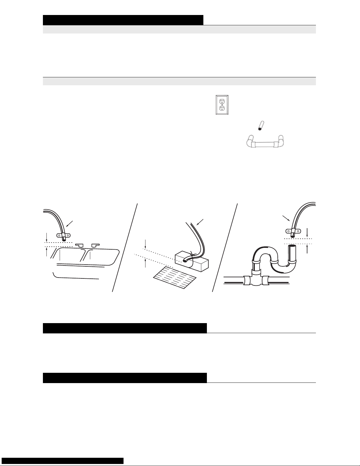
2. Where will you run the drain line/waste tube?
(see illustration below)
3. Where is a 110V outlet within 6 feet of the
softener?
Optional: Run a longer wire to most any 110V
outlet.
4. Do you need to run a hard-water line to
your outside hose bibs, pool llers or irrigation
system?
5. Where can the water softener sit on a rm,
fairly level concrete oor or slab?
Determine the location of your water softener/conditioner, taking into account the above factors, and
determine what materials and tools will be needed for installation. You are now ready to move on to
Step 1 of the Installation Procedures.
INSTALLATION PROCEDURES
WARNING: Do not attempt to remove the red
locking bar (KS5 & KS10 only). The locking bar
is for service only and should only be removed by
a trained softener technician.
NOTE: The Air-Check sight glass will NOT have
a rubber ball in it. The air-check on Krystal
Pure™ softeners is located in the brine well in the
brine tank.
STEP 1 CONNECT TO WATER SUPPLY
A. Shut off the main water supply to the house.
Open the hose bib to relieve pressure and
drain out water. Close the hose bib. Place a
bucket or the softener brine tank under the
softener loop to catch the excess water that
will spill out when you cut the pipe. Cut the
plumbing loop off. Determine the inlet side
of the loop by turning the main water on
very slightly until water comes out of one of
the sides of the loop. This is the inlet supply.
WARNING: You must connect the incoming side of the softener/conditioner to the
inlet supply from the loop. Failure to con-
nect with the proper directional ow can dam-
waste tube
tubería del desagüe
1-½”
airgap
sink basin
lavabo
floor drain
cloaca del desag üe
P-trap
trampa-p
1½” airgap
trampa d e aire
waste tube
tubería del desagüe
waste tube
tubería del desagüe
1½”
trampa
de aire
1-½”
airgap
1½”
trampa
de aire
IF YOUR HOME IS NOT PRE-PLUMBED
INSTALLATION INSPECTION
IS YOUR HOME PRE-PLUMBED?
Your home is pre-plumbed for a water softener/conditioner if you have a loop in the garage or laundry
room. Typically, there will be 110 volt outlet within 6 feet of the loop and a ½” drain line stubbed out
of the wall. If your home is pre-plumbed, skip now to Step 1 of Installation Procedures. CAUTION:
Before starting up system, check water softener drain line to insure that it will drain properly.

10/12 KPWS • 8
*Eficiencia: Una eficiencia calificado del suavizador
es un suavizador de DIR que también cumple con las
especificaciones de funcionamiento especificos destinados a reducir la cantidad de salmuera regenerante
y agua usada en su operación. La eficiencia calificado
del los suavizadores de agua tendrá una eficiencia de
no menos de 3350 granos de cambio de la dureza total
por libra de sal (basado en la equivalencia en NaCL)
(477 granos de cambio de la dureza total por kilogramo
de sal), y no deberan recibir mass al de lo que la calificacion de la lista. El índice de eficiencia es válida sólo
en el valor predetermindo de fábrica de dosis de sal
y velocidad máxima flujo de servicio. La eficiencia se
mide por un ensayo de laboratorio descrito NSF/ANSI
44. La prueba representa la maxima eficiencia posible
que el sistema pueda lograr. La eficiencia operacional
es la eficiencia real lograda después de que el sistema
ha sido instalado. Es típicamente menos la eficiencia
debido a factores individuales de la aplicación, incluy-
endo la dureza del agua, el uso de agua, y otros contaminantes que reducen la capacidad de suavizadores.
**El hierro se puede utilizar en varias formas, si en su
suministro de agua se encuentran ciertos tipos de hierro, usted necesitará el pretratamiento apropiado.
***Continuo significa que una caja de enchufe con
voltaje continuo de 110 no se puede apagar con un interruptor de pared. Estos sistemas han sido evalua-
dos según su rendimiento y cumplen con las normas de NSF/ANSI 44 para la demanda especifica del
rendimiento, la cual está verificada y sostenida por
la información de las pruebas. Demanda de contaminantes específicos no reducidos. ¹Los interme-
dias de flujo no representan la velocidad de servicio de
flujo maximo usado para determinar la calificacion de
la capacidad y eficiencia del suavizador. La operación
continua en velocidades de flujo mayores que la velocidad de servicio de flujo máximo puede afectar el rendimiento de la capacidad y eficiencia.
1. ¿Cómo obtendrá agua del suministro de
agua principal al suavizante/acondicionador
de agua?
2. ¿Dónde pondrá la tubería del desagüe?
(consulte la ilustración a la izquierda)
3. ¿Dónde está una caja de enchufe de 110
voltios dentro de un margen de 6 pies del suavizador?
Opcional: Utilice una conexión a cualquier caja
de enchufe de 110 voltios.
4. ¿Necesitará instalar una tubería de agua
dura afuera de sus mangueras, ltros de la piscina, o del sistema de irrigación?
5. ¿Dónde puede colocarse el suavizante de
agua para que quede sostenido rme a un
nivel adecuado con piso de concreto o tabla?
PROCEDIMIENTOS DE INSTALACIÓN
INSPECCIÓN DE INSTALACIÓN
¿SU CASA TIENE LAS CAÑERIAS CORRECTAS?
Su casa tiene las cañerías correctas para el
sistema suavizante/acondicionador de agua si
tiene una caño curvo en su cochera o su cuarto
de lavar. Típicamente, habrá una caja de enchufe
de 110 voltios en un margen de 6 pies de la curva
y a media pulgada de la tubería del desagüe que
sale de la pared. Si su casa tiene las cañerías
correctas, siga con el Paso 1 de Procedimientos
de instalación.
ADVERTENCIA: Antes de empezar el sistema,
revise la tubería del desagüe del suavizante de
agua para asegurar que el desagüe funciona apropiadamente.
Si su casa no tiene las cañerías correctas para el suavizante de agua, le recomendamos que un profesional le instale sus cañerías. Si usted intenta instalar el sistema, usted deberá determinar donde
será la ubicación del suavizante/acondicionador de agua.
La mejor ubicación depende de algunas preguntas:
Determine la ubicación del suavizante/acondicionador de agua tomando en cuenta los factores establecidos y determine qué materiales y herramientas serán necesarias para la instalación. Ahora
usted está listo para seguir con el Paso 1 de los Procedimientos de instalación.
ADVERTENCIA: No intente remover la barra
del cerrojo rojo (solamente en los sistemas
KS5 y KS10). La barra del cerrojo rojo es para
uso solamente de mantenimiento y sólo debe de
ser removida por un técnico adiestrado en suavizantes de agua.
NOTA: El vidrio del Examinador de aire NO ten-
drá una bola de goma. En los suavizantes de
Krystal Pure™ el examinador de aire está localizado en el pozo de salmuera en el depósito de
salmuera.
SI SU CASA NO TIENE LAS CAÑERIAS CORRECTAS

9 • 10/12 KPWS
age the water softener/conditioner and your
household plumbing.
B. Prepare SourceSelect™ bypass valve or yoke
for piping connections.
1. KS5 yoke connection:
a. Appl y O-rings (3-required and
included) to tank meter adapter. Lubri-
cate with silicone (provided).
b. Slip yoke into position over O-rings.
c. Connect yoke to meter adapter using
(4) nuts and bolts (provided).
d. Install drain hose barb. Use Teon
tape on threads. Hose barb can point up
or down.
e. Install ¾” or 1” mip adapters, or ¾” or 1”
union nipples and valve is ready for pipe
connections.
2. KS5 and KS10 SourceSelect™ bypass
valve connection:
a. Apply O-rings (3-required and
included) to tank meter adapter. Lubri-
cate with silicone (provided).
b. Slip bypass valve into position over
O-rings.
c. Connect bypass valve to meter adapter
using (4) nuts and bolts (provided).
d. Install drain hose barb. Use Teon
tape on threads. Hose barb can point up
or down.
e. Insert tailpieces through union nuts.
f. Attach tailpieces by soldering to the
inlet and outlet of the plumbing loop.
g. Place rubber gaskets into the union
nuts and thread onto the bypass
valve body. It is not necessary to use
lubricant or sealant on rubber gasket or
union nuts.
h. Place SourceSelect™ valve into the
bypass position by rotating the handles
so they are both perpendicular to the ow
path of the inlet and outlet water stream.
3. KS15HE, KC10, and KC15 (High-Flow)
SourceSelect™ bypass valve connec-
tion:
a. Install drain hose barb before attaching
SourceSelect™ bypass valve. Use
Teon tape on threads.
b. Insert the rubber gaskets into the
union nuts on the SourceSelect™ bypass valve.
c. Thread the bypass onto the valve
control body, hand-tightening both union
nuts. It is not necessary to use lubricant
or sealant on rubber gasket or union nuts.
d. Insert tailpieces through union nuts.
e. Attach tailpieces by soldering to the
inlet and outlet of the plumbing loop.
f. Place rubber gaskets into the union
nuts and thread onto the bypass valve
body. It is not necessary to use lubricant
or sealant on rubber gasket or union nuts.
g. Place SourceSelect™ valve into the
bypass position by rotating the handles
so they are both perpendicular to the ow
path of the inlet and outlet water stream.
STEP 2 CONNECT TO DRAIN
Typical drain line runs to a oor drain, washing machine drain, sanitary sewer line with a p-trap, a
sink drain or a sump. CAUTION: Check with all local plumbing codes to insure proper instal-
lation in your area. An air-gap may be required. Be sure to install proper drain line size (see
specications or Step 2B for sizing).
A. Slide a ½” I.D. tube onto hose barb located
on the back of the valve control body, (you
may want to secure tube with a hose clamp,
not provided). Connect the tubing to the drain
stub out provided with your pre-plumb loop.
Some pre-plumbs may provide an ABS drainpipe to run drain line to. CAUTION: Be sure
drain line discharges properly into a drain
to prevent ooding.
B. If the following conditions exist, it is
recommended to increase the drain line
tubing from ½” to ¾” I.D.
1. Drain line run is over 20’.
2. Drain line vertical run is over 10 feet high
with incoming water supply pressure of 60
PSI. (You can increase or decrease height
of run 2 feet per 10 PSI. variations in either
direction, i.e. 12 feet vertical run with 70
PSI. or 8 feet vertical run with 50 PSI.).
3. Backwash rates exceed 5 gpm (see
specications sheet).
STEP 3 CONNECT BRINE LINE
A. Take off the cap from the brine well and take
out the oat assembly.
B. Place the well into the brine tank and align the
holes in the brine well to the holes in the brine

10/12 KPWS • 10
A. Apague el suministro de agua principal de la
casa. Abra las mangueras para relajar la
presión y drenar el agua completamente.
Después cierre las mangueras, y coloque debajo del caño curvo una cubeta o el depósito
de salmuera para coger el exceso de agua que
saldrá cuándo usted corte la tubería. Corte el
caño curvo, y abra un poco el suministro de
agua hasta que salga agua de uno de los lados, para determinar cual es el lado donde
sale agua del caño curvo. Este es el suministro entrante. ADVERTENCIA: Usted debe
conectar el suavizante/acondicionador de
agua al lado del suministro entrante. Si no
conecta las cañerías con la dirección del flujo
apropiado puede dañar el sistema de suavizante/acondicionador de agua y las cañerías
de su casa.
B. Prepare la válvula de derivación de selección
de fuente o el yugo de las conexiones de las
tuberías.
1. Yugo de la conexión del sistema KS5:
a. Apliqué los empaques en forma de anillo
(se requieren 3 y están incluidos) al contador y adaptador del depósito. Lubrique
con silicón (incluido).
b. Deslice el yugo a la posición sobre los
empaques en forma de anillo.
c. Conecte el yugo al adaptador del
contador utilizando las (4) tuercas y cerrojos (incluidos).
d. Instale el adaptador de la manguera del
desagüe. Utilice la cinta de teflón en las
roscas. El adaptador de la manguera puede apuntar hacia arriba o hacia abajo.
e. Instale los adaptadores de ¾ o 1
pulgada, o las uniones de empalme de ¾
o 1 pulgada y ahora la válvula está lista
para conectar de la tubería.
2. Conexión de la válvula de derivación
SourceSelect™ en los sistemas de
KS5 y KS10:
a. Coloque los empaques en forma de
anillo (se requieren 3 y están incluidos)
al contador y adaptador del depósito. Lubrique con silicón (incluido).
b. Deslice la válvula de derivación en la
posición sobre los empaques en forma
de anillo.
c. Conecte la válvula de derivación al
adaptador del contador utilizando las (4)
tuercas y cerrojos (incluidos).
d. Instale el adaptador de la manguera del
desagüe. Utilice la cinta de teflón en las
roscas. El adaptador de la manguera puede apuntar hacia arriba o hacia abajo.
e. Inserte los cabos a través de las uniones
de las tuercas.
f. Adhiera los cabos soldando en la salida y
la entrada del caño curvo.
g. Coloque los empaques de goma en
las uniones de las tuercas y la rosca
en el cuerpo de la válvula de deri-
vación. No es necesario utilizar lubrican-
te o sellador en los empaques de goma o
las uniones de las tuercas.
h. Coloque la válvula de la Selección de
fuente en la posición de derivación ro-
tando los mangos para que los dos estén
perpendiculares al paso de la salida y
entrada del flujo de la corriente del agua.
3. Conexión de la válvula de derivación
SourceSelect™ (Flujo Fuerte) en los
sistemas KS15HE, KC10 y KC15:
a. Instale el adaptador de la manguera
antes de adherir la válvula de derivación
SourceSelect™. Utilice cinta de teflón en
las roscas.
b. Inserte los empaques de goma en las
uniones de las tuercas en la válvula de
derivación SourceSelect™.
c. Enrosque la derivación al cuerpo de la
válvula de control, y ajuste con la mano
las uniones de las tuercas. No es necesario utilizar lubricante o sellador en los
empaques de goma o las uniones de las
tuercas.
d. Inserte los cabos a través de las uniones
de las tuercas.
e. Adhiera los cabos soldando la salida y
entrada del caño curvo.
f. Coloque los empaques de goma en
las uniones de las tuercas y roscas en
el cuerpo de la válvula de derivación.
No es necesario utilizar lubricante o
sellador en los empaques de goma o las
uniones de las tuercas.
g. Coloque la válvula de la Selección de
fuente en la posición de derivación rotando los mangos para que los dos estén
perpendiculares al paso del flujo de la
salida y entrada de la corriente del agua.
PASO 1 CONEXIÓN AL SUMINISTRO DE AGUA
PASO 2 CONEXIÓN AL DESAGÜE
La tubería típica del desagüe corre al desague del piso, al desagüe de la lavadora, al conducto
11 • 10/12 KPWS
tank.
C. Take out the ½” 90° elbow hose barb and
remove the rubber washer and plastic nut.
D. From the outside of the brine tank, install the
elbow tting through the bottom hole.
E. Place the rubber washer onto the threads
inside the brine well and secure with the plastic nut.
F. Remove the nylon nut from the oat
assembly; insert the oat assembly inside the
brine well with the bolt through the small hole
opposite the elbow tting. Secure with the nylon nut.
G. Connect one end of the 3/8” black line to the
brine oat tting located at the top of the brine
well inside the brine tank. NOTE: The brine
line enters the brine tank through the hole
aligned with the tting for the brine oat.
H. Connect the other end of the 3/8” black line
to the brine line ow control tting located just
behind the control head using the black nut
provided. The line enters from the left side facing the control.
I. Be sure all ttings and connections are tight.
(See diagram on page 21).
STEP 4 SYSTEM START-UP
KS5 AND KS10 START UP:
NOTE: The following steps will require turning the indicator knob (see Figure 1 below) to various posi-
tions. Push the indicator knob in while manually rotating the camshaft located behind the controller by
hand (COuNterCLOCKwiSe) until indicator knob points to the desired position.
1. Remove valve cover by releasing the plastic
clip from the back and lifting the cover up and
forward.
2. Rotate indicator knob to the BACKWASH
position (COUNTERCLOCKWISE).
3. Fill the softener/conditioner tank with water.
a. With house water supply off, open the
SourceSelect™ bypass valve.
b. Open water supply valve very slowly to
approximately ¼ open position.
4. When all of the air has been purged from
the tank (water begins to ow steadily from the
drain), open the main water supply all the way.
Allow water to run to drain until clear.
5. Turn off water supply and let the unit stand
for about ve minutes to allow all trapped air to
escape from the tank.
6. Add the initial amount of water to the brine
tank manually with a bucket or a hose. Add
approximately 3 gallons of water to the brine
tank.
7. Slowly turn the water supply valve
completely open. Place the conditioner
into operation by turning the indicator knob
COUNTERCLOCKWISE to the BRINE/
SLOW RINSE position.
8. With conditioner in this position, observe the
water level in the brine tank for several minutes
to check that the level is going down. If water level does not recede, then make sure the
brine line ttings are tight and no air can leak
into connections.
9. Advance the indicator knob to the FAST
RINSE/REFILL position. Let conditioner run
in this position for a minute or so.
10. Advance the indicator knob to just past the
FAST RINSE/REFILL position but NOT all
the way to the CONDITIONED WATER posi-
tion. Run water from a nearby faucet until the
water is clear. Proceed to Step 5 Electrical
Connections.
NOTE: The following steps will require turning the cycle indicator (see Figure 2 on pg. 12) to various
positions. Manually rotate the camshaft, located behind the controller, by hand (COUNTERCLOCK-
KS15HE START UP:
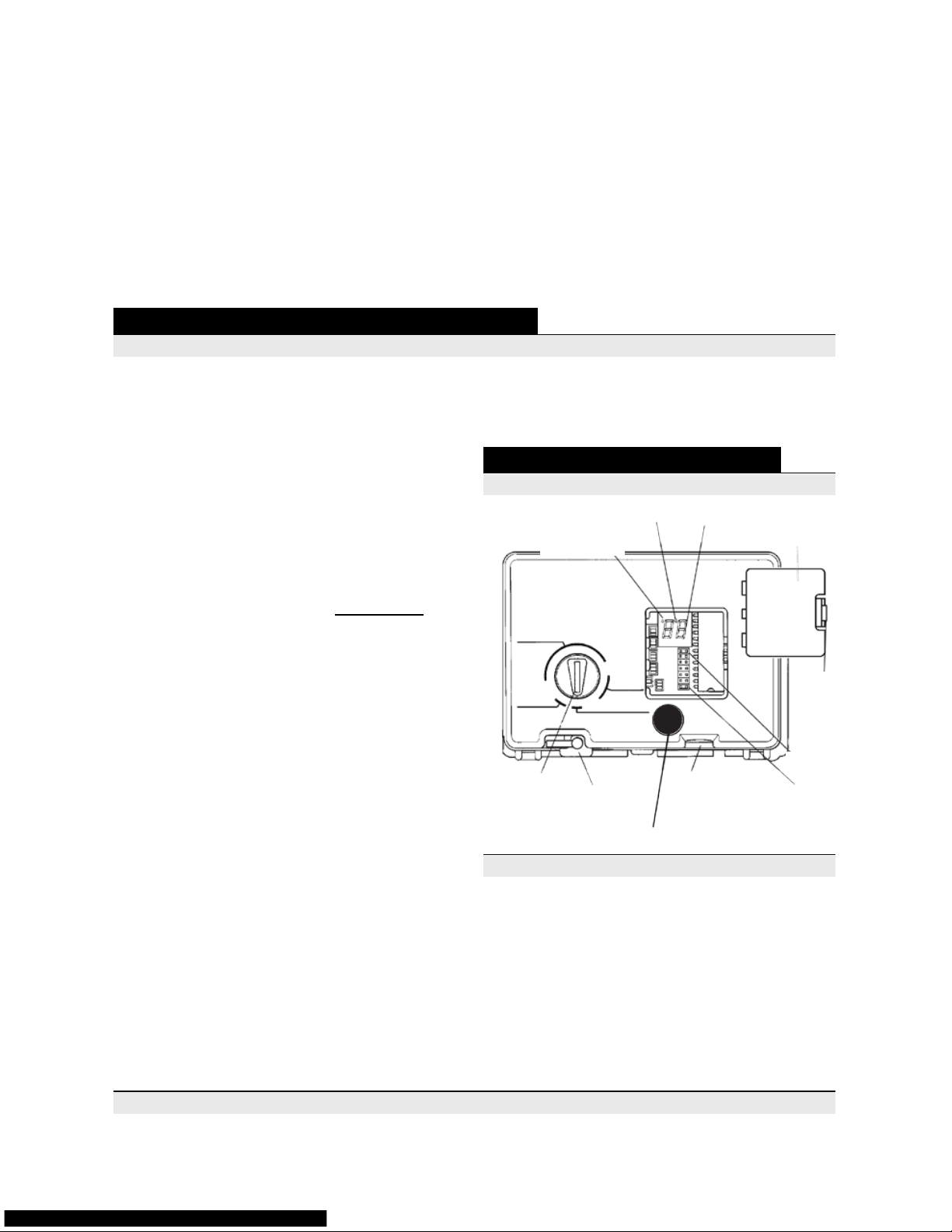
Water Flow Indicator
Indicador del f lujo de ag ua
PM Indicator
Indicador de PM
Indicator Knob
Perilla guia
Raised
Tab
Aleta
alzada
BRINE/
SLOW RINS E
FAST RI NSE/
REFILL
BACKWAS H
CONDITIONED WATER
MANUAL REGENERATION:
PRESS BUTT ON & RELEASE
Press
To Set Time
FLOW
PM
TIME
HARDNESS
CAPACITY
A
B
SPARE
Time
Locking Pin
Clavija aseguradora del tiempo
Hour Time Display
Ventana de presentación
Transformer Plug
Receptacle
Receptor del
transformador
Access Door
Puerta de
acceso
Time Set Button
Botón “ Time Set”
Spare
Jumper
Interruptor
extra
Jumper
Interruptor
CONTROL DE LOS SISTEMAS KS5 • KS10
KS5 • KS10 CONTROLLER
FIGURE 1 • FIGURA 1

10/12 KPWS • 12
PASO 3 CONEXIÓN DE LA TUBERÍA DE SALMUERA
A. Descubra la tapa del pozo de salmuera y
remueva el ensamblado del otador.
B. Coloque el pozo de salmuera dentro del de
positó y alinee los oricios del pozo de salmuera a los oricios del depositó.
C. Remueve el codo dentado para manguera
de ½ pulgada y de 90º; remueva la arandela
de plástico y las tuercas de plástico.
D. Desde afuera del depositó de salmuera,
instale el conectador del codo dentado a
través del oricio de abajo.
E. Coloque la arandela de plástico entre los
hilos dentro del pozo de salmuera y sujételo
con la tuerca de plástico.
F. Remueva la tuerca de nylon del ensamblado
del otador. Inserte el ensamblado del otador adentre del pozo de salmuera dentro del
depositó de salmuera con el cerrojo a través
del oricio pequeño en contra del conector del
codo dentado.
G. Conecte un lado de la tubería negra de 3/8
de pulgada al otador localizado arriba del
pozo de salmuera dentro del depositó de salmuera. NOTA: La tubería de salmuera entra al
depositó a través del oricio que alinea con el
conectador del otador de salmuera.
H. Conecte el otro lado de la tubería negra de
3/8 de pulgada al conectador de la tubería de
control de ujo de salmuera localizado detrás
de la cabeza del control utilizando la tuerca
negra proveída.
I. Asegúrese que todos los conectadores y
conexiones estén sujetos. (consulte el diagrama en la página 21)
PASO 4 ENCENDIDO DEL SISTEMA
INICIO PARA LOS SISTEMAS KS5 Y KS10:
NOTA: Los siguientes pasos requieren girar la perilla guía (consulte la Figura 1 en la página 12) a
varias posiciones. Empuje la perilla guía mientras manualmente gira (A LA IZQUIERDA) el árbol de
levas, localizado detrás del control, hasta que la perilla guía este en la posición deseada.
1. Remueva la cubierta de la válvula liberando
por detrás el pasador de plástico y levantando
la tapa hacia arriba y adelante.
2. Gire (A LA IZQUIERDA) la perilla guía a la
posición de “BACKWASH.”
3. Llene el depósito del suavizante/
acondicionador con agua.
a. Con el suministro de agua de su casa
cerrado, abra la válvula de derivación
SourceSelect™.
b. Abra la llave del suministro de agua
lentamente aproximadamente a ¼ de la
posición de abierto.
4. Cuándo todo el aire haya sido extraído del
depósito (el agua empezara a fluir constantemente del desagüe), abra completamente
el suministro de agua principal. Deje el agua
correr al desagüe hasta que esté clara.
5. Cierre el suministro de agua y deje la unidad
reposar por más o menos 5 minutos para que
A. Deslice el caño I.D. de ½ pulgada a el
adaptador de la manguera localizada en la
parte de atrás del cuerpo de la válvula de
control, (usted puede asegurar el caño con
la mordaza de la manguera, no incluida). Conecte el caño que sale de la pared al fragmento del desagüe, proveído en su caño curvo.
Alguna cañería puede proveer una pipa de
desagüe ABS que se dirige a la tubería del
desagüe. PRECAUCIÓN: Asegúrese de dre-
nar la tubería apropiadamente para prevenir inundaciones.
B. Si las siguientes condiciones existen, es
recomendado incrementar la cañería I.D. de
la tubería del desagüe de ½ a ¾ de pulgada.
1. La tubería del desagüe es más grande
que 20 pies.
2. La tubería vertical del desagüe es más de
10 pies de altura con una presión de 60 PSI
en el agua entrante del suministro. (Usted
puede incrementar o disminuir la altura en
cualquier dirección por 2 pies con 10 PSI.
de variación, es decir, 12 pies verticales
con 70 PSI. o 8 pies verticales con 50 PSI.).
3. La coeficiencia de lavar de tras excede
los 5 gpm (consulte la Hoja de
especificaciones).
de la cloaca del sanitario con una trampa-p, al desagüe del lavabo o al pozo para el drenaje. PRE-
CAUCIÓN: Revise todas las normas locales de cañerías de su área para hacer una instalación
apropiada. Una trampa de aire puede ser requerida. Asegúrese de instalar el tamaño apro-
piado para la tubería del desagüe (consulte las especificaciones o el Paso 2B para Tamaños).
13 • 10/12 KPWS
1. Remove valve cover by depressing the two
tabs on the sides of the cover and lifting the
front of the cover up and off.
2. Rotate cycle indicator (COUNTERCLOCK-
WISE) to the BACKWASH position.
3. Fill the softener/conditioner tank with water.
a. With house water supply off, open the
SourceSelect™ bypass valve.
b. Open water supply valve very slowly to
approximately ¼ open position.
4. When all of the air has been purged from
the tank (water begins to ow steadily from the
drain), open the main water supply all the way.
Allow water to run to drain until clear.
5. Turn off water supply and let the unit stand
for about ve minutes to allow all trapped air to
escape from the tank.
6. Add the initial amount of water to the brine
tank manually with a bucket or a hose. Add
approximately 3 gallons of water to the brine
tank.
7. Slowly turn the water supply valve completely open. Place the conditioner into operation by
slowly turning the cycle indicator COUNTER-
CLOCKWISE to the BRINE/SLOW RINSE
position.
8. With conditioner in this position, observe the
water level in the brine tank for several minutes to check that the level is going down. If
water level does not recede, then make sure
the brine line ttings are tight and no air can
leak intothe tting connections.
9. Advance the cycle indicator to the FAST
RINSE position. Let conditioner run in this po-
sition for a minute or so.
10. Advance the cycle indicator to the REFILL
position. Hold this position until water starts
to ow through the brine line into the brine
tank.
11. Advance the cycle indicator COUNTER-
CLOCKWISE to the REGENERATION COMPLETE position and run water from a nearby
faucet until the water is clear. Proceed to Step
5 Connect Electrical.
Plug transformer into a 110 VAC outlet that is
NOT controlled by a wall switch. Connect the
plug of the transformer into the Transformer Plug
Receptacle located at the bottom of the control
housing (see Figure 1 on page 11).
STEP 5 CONNECT ELECTRICAL
STEP 6 PROGRAM THE VALVE CONTROL
KS5 AND KS10 PROGRAMMING:
1. Time of Day Setting
Open the access door to access the jumper
settings. The jumper should be on the TIME
jumper. Set the time of day to the nearest hour
by pressing the black TIME SET button. PM
hours are indicated by a light next to the letters
PM on the display window.
NOTE: The unit is factory-set to regenerate at
2:00a.m. If you prefer to have the unit regenerate at an earlier or later time, simply set the
current time of day accordingly (e.g., to have
the unit regenerate at 4:00a.m. – two hours
later - set the clock two hours earlier than the
actual time of day. If it is actually 2:00 p.m., set
the time to 12:00 p.m.). Make sure the Timer
Locking Pin is always in the horizontal position during operation.
2. Hardness Setting
Move the jumper to the pins next to the word
HARDNESS. Press the black TIME SET button until the hardness of the incoming water
supply is displayed. NOTE: The factory default
is 18 GPG (Grains Per Gallon). It is a good
idea to set your hardness a few grains higher
than your actual hardness because hardness
can vary throughout the year. Check with your
local water supply company or municipality to
nd out the hardness in your area.
3. Capacity Setting
It is NOT necessary to change the capacity
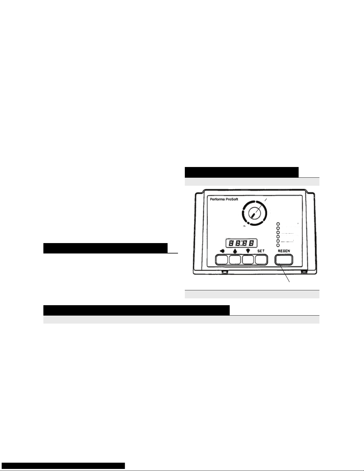
Cycle Indicator
Regen Button
REGENERATION
COMPLETE
Time of Day
PM
SET
Capacity
Salt Amount
Time of Regen
Hardness
Regen Time
Remaining
KS15HE CONTROLLER
CONTROL DEL SISTEMA KS15HE
FIGURE 2 • FIGURA 2
WISE) only until cycle indicator points to the desired position
F
A
S
T
R
I
N
S
E
B
R
I
N
E
/
S
L
O
W
R
I
N
S
E
B
A
C
K
W
A
S
H
R
E
F
I
L
L
 Loading...