

Krystal Pure KR5, KR15, KR10 Owner's Manual
1
For Krystal Pure™ Reverse Osmosis Systems KR5 • KR10 • KR15
Para sistemas de ósmosis inversa
Owners Manual
Manual del propietario
Includes: Installation and Service Procedures, Specifications and Operation Guidelines.
Incluye: Procedimientos de instalación y servicio, Especificaciones y Guías de operación.

2
| Krystal Pure™ | Reverse Osmosis System Manual
INTRODUCTION 3
MANY USES AND BENEFITS OF REVERSE OSMOSIS WATER 3
TOOLS & MATERIALS RECOMMENDED FOR NORMAL INSTALLATION 3
CONTENTS OF PACKAGE 3
SPECIFICATIONS AND LIMITATIONS 4
WARNINGS 4
PHOTO OF R/O AND PARTS 5
INSTALLATION PROCEDURES 5
STEP 1 POSITION SYSTEM 5
STEP 2 FAUCET INSTALLATION 5
FIGURE 1 6
STEP 3 EASY TAP ADAPTER INSTALLATION 5
STEP 4 DRAIN SADDLE CLAMP INSTALLATION 6
FIGURE 2 7
STEP 5 STORAGE TANK PREPARATION 6
STEP 6 TUBING CONNECTIONS 7
STEP 7 SYSTEM START-UP PROCEDURES 7
STEP 8 REFRIGERATOR ICE MAKER HOOK UP 8
STEP 9 RECOMMENDED FILTER SERVICE LIFE 8
FILTER REPLACEMENT LIST 9
STEP 10 FILTER CHANGING PROCEDURES 9
STEP 11 RECOMMENDED SANITIZING PROCEDURE 9
STEP 12 SERVICE AND MAINTENANCE RECOMMENDATIONS 9
REPLACEMENT PARTS LIST 10
TROUBLESHOOTING GUIDE 10
KRYSTAL PURE™ R/O SCHEMATIC 12
PERFORMANCE DATA SHEET NSF/ANSI 58 14
MANUFACTURERS WARRANTY 15
WARRANTY REGISTRATION CARD 16
TABLE OF CONTENTS

3
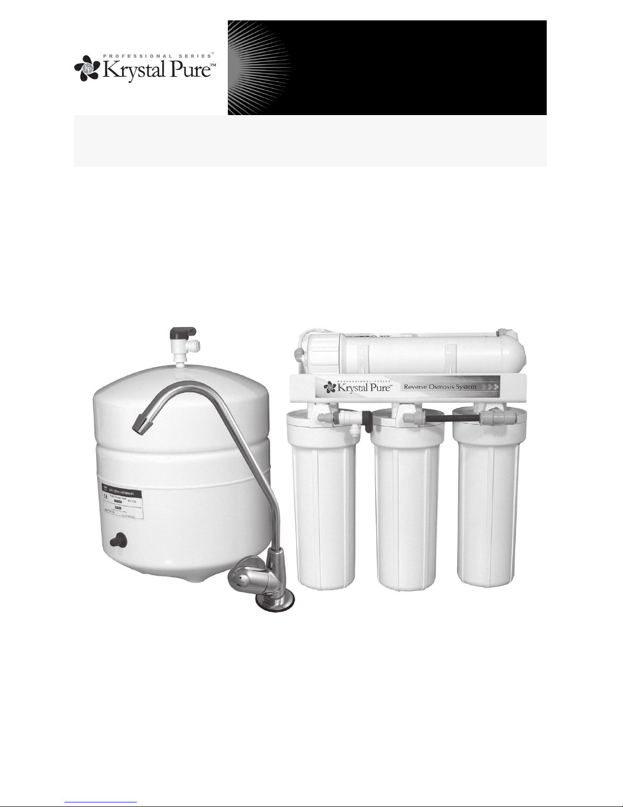
Congratulations, you have purchased one of the highest quality Reverse Osmosis, “R/O” systems
available today. This unit combines a series of different filtration processes into one single module
that makes bottle-quality water right in your own home or office. This system has been engineered
with only the finest quality components and materials. The system works connected to most potable
city water supplies.
Obtain all materials and tools needed for installation before starting. Please read entire manual carefully before proceeding with installation. Failure to follow manual’s guidelines could cause personal
injury or property damage. Be sure to check household plumbing for signs of leaks, corrosion and
aging. Correct these problems before attempting to install your new R/O system.
1. Quality Drinking Water
2. Quality Ice Cubes
3. Car Batteries and Window Washer
4. Removing some carpet stains
5. Drinking water for pets
6. Watering plants
7. Some humidifiers
8. Washing windows
9. Making coffee, juice and teas
10. Use for cooking
11. Rinsing vegetables
12. Brushing teeth
13. Rinsing hair after washing
14. Steam irons
15. Office coolers
16. Bottled Water
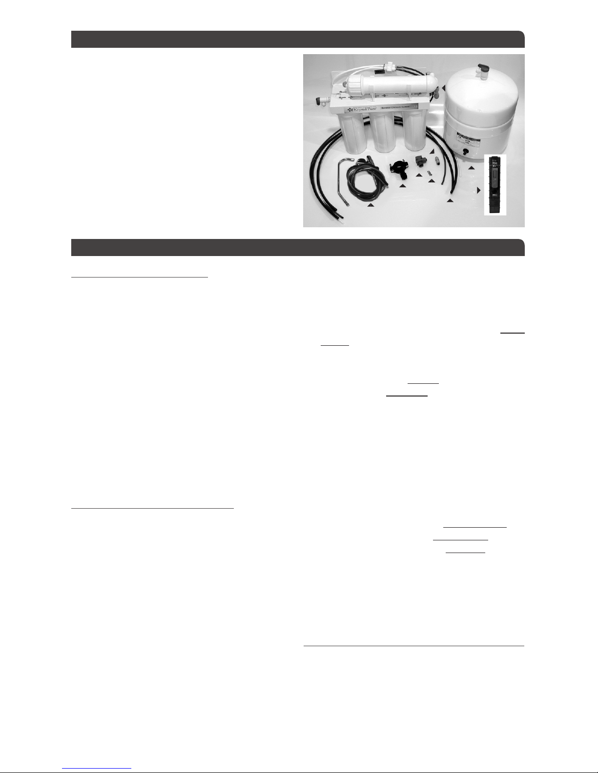
❱ Filter Pac/R/O module
❱ Storage Tank
❱ Owner’s Manual
❱ Warranty Registration Card
❱ Standard air-gap faucet or optional colored
faucet.
❱ Water Quality Monitor (KR15 only)
❱ Parts Bag:
a. Easy Tap Adapter w/washer (plastic)
b. Drain Clamp (black plastic)
c. ¼” Coupler (plastic) for use w/air gap faucet
d. Faucet Adapter plastic (7/16” fip × 3/8” push)
e. Tank Ball Valve
f. Mounting Screws
1. Adjustable Wrench (2)
2. Phillips Screw Driver
3. 3/8” drill motor with a 3/8” drill bit
4. Teflon Tape
5. Safety Glasses
6. Step 2: Faucet Installation (optional) 1¼” hole
saw appropriate for sink material to be drilled
7. Step 8: Ice Line to refrigerator (optional) 3/8”
polyethylene or polypropylene tubing. 3/8”
× 3/8” × 3/8” plastic compression T-fitting
MANY USES AND BENEFITS OF REVERSE OSMOSIS WATER
INTRODUCTION
CONTENTS OF PACKAGE
TOOLS & MATERIALS RECOMMENDED FOR NORMAL INSTALLATION

4
| Krystal Pure™ | Reverse Osmosis System Manual
1. Only use with potable water supplies (Water
must be microbiologically safe).
2. Installation of R/O system must Comply with
state and local laws and regulations.
3. Check for leaks after installation or service
as system is reaching standard operating pressure and temperature. Check for leaks periodically thereafter. A system may be inadvertently moved or jarred while other items
are moved under the sink. If a fitting is accidentally loosened, a leak could result causing
damage to your cabinet.
4. Do not let system freeze. Allow to warm up
to room temperature before installing. Best to
be installed indoors with air temperature between 60° - 85° F.
5. Attach to cold water supply only.
6. Never drain R/O tank completely without
first turning off the refrigerator ice maker.
7. Air-gap faucet may cause a slight noise at first
but noise should diminish in about a week. If
noise continues, adjusting drain clamp may
help reduce noise. Also, install faucet so
air-gap faucet hole will drain into the sink if
drain line gets plugged from obstruction in
the drain line.
8. This reverse osmosis system contains a replaceable component critical to the efficiency of the system. Replacement of the reverse
osmosis component should be with one of
identical specifications, as defined by the
manufacturer, to assure the same efficiency
and contaminant reduction performance.
9. Failure to follow recommended service intervals or use of filters and parts other than
those recommended by the manufacturer
may void warranty.
10. Drain R/O tank completely at least twice a
year. If daily use averages less than a gallon
per day, drain every two weeks. (See page 3
for Many Uses).
11. We recommend having all porcelain/enamel-coated sinks professionally drilled.
12. Sanitizing most R/O systems on a yearly basis
is important for reducing bacteria build-up.
13. All membrane performance and life cycles
may be affected by severe water conditions.
Varying mineral content like hardness and
iron will require varying filter change intervals. Some customers choose pretreatment
options like water softening or iron reduction
systems to protect the entire home.
SPECIFICATIONS AND LIMITATIONS
INCOMING WATER SUPPLY
pH
3 min. to 11 max.
Water Pressure
40 PSI min. to 85 PSI max.
Total Dissolved Solids (TDS)
2000 PPM max.
Temperature Air and Water
40° F min. to 110° F max.
Hardness
Water Softener Recommended over 10 GPG
Iron Content <1 PPM max.
SYSTEM
System Dimensions 16” × 15.5” × 7”
Storage Tank Dimension 15.5” × 11”
Rejection Rate Up to 98% TDS*
Storage Capacity Up to 3.2 Gallons*
Production Capacity Membrane Rating 24 gallons per day*
*NOTE: These specifications are not the certified results and can vary greatly depending on feed water makeup,
i.e. pressure, temperature, TDS, and hardness. See Performance Data Sheet for the actual WQA Certified results
under standard test conditions on page 25. Regular maintenance and filter replacement are necessary for system’s
performance and longevity.
WARNINGS
5
STEP 1 POSITION SYSTEM
The R/O system needs both a water supply and
access to a drain. The R/O system is designed to
fit under most sinks. The kitchen sink is the most
common location for the R/O install. Remove all
system components from boxes and determine
the location for placement of the Filter Pac/R/O
module, tank, and faucet.
If you desire to hang the Filter Pac/R/O module,
use mounting screws, placing them to align with
holes in the bracket (make sure the cabinet wall
is thick enough to support the Filter Pac/R/O
module and that the mounting screws will not
pierce through the wall). Hang Filter Pac/R/O
module to assure sufficient space is allowed.
Remove Filter Pac/R/O module from the wall for
now and continue with install.
STEP 2 FAUCET INSTALLATION
1. Check for an extra hole in the sink. You must
drill a 1¼” hole for the faucet if the sink does
not have one.Determine Location of Faucet
Hole: Check underneath sink before drilling.
Make sure there are no obstructions. Drilling
a Stainless Steel Sink: Drill a 1¼” hole with a
hole saw or hole punch for an air-gap faucet.
Smooth out rough edges with a file if necessar y.Porcelain/Enamel-Coated Stainless
or Cast Iron Sink: The manufacturer recommends having this type of sink professionally
drilled because of possibility of chipping or
cracking. If you are attempting to drill, use extreme caution. Obtain the proper tools necessary to drill through the sink material. Follow
the drill manufacturers instructions for your
type of sink. Place an old towel under the
sink to catch any metal filings and to make
clean up easy. After drilling, clean up metal
filings quickly to avoid staining the porcelain.
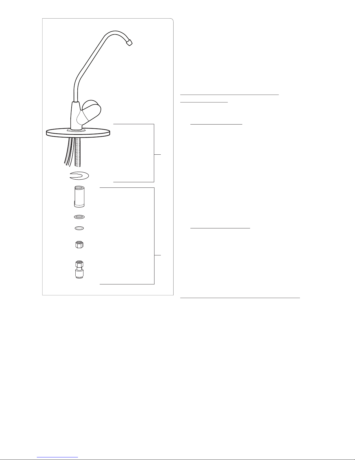
2. Install Air-gap Faucet: Pre-assemble faucet
prior to installing on the sink. Place the white
spacer onto faucet stem flat side toward tubing and open end upward. Slide spacer up the
stem leaving enough room for the thickness of
the sink. Place the washer onto the stem and
thread on the 9/16” nut up to the spacer. Attach the plastic 3/8” faucet adapter fitting to
the base of the faucet stem (Do not over-tight-
en) (see A in Figure 1 page 6).
3. Guide the (2) tubes and the faucet stem through
the hole on the sink until the faucet rests on
top of the sink. Center the faucet over the hole.
Position the faucet so the air-gap hole and the
faucet lever point toward the sink basin (in case
drain tube plugs causing water to spill out of
the air-gap hole). Insert the slotted washer under the sink between the white spacer and the
base of the sink. Tighten the 9/16” nut securing
the white spacer tight against the sink (see B in
Figure 1 page 6). Faucet may require repositioning before final tightening. Remove short packing tubing from top of faucet and insert faucet
spout by pushing spout straight into the hole
until it seats.
STEP 3 EASY TAP ADAPTER INSTALLATION
Turn off cold water supply to the sink faucet
and relieve pressure by opening the cold water
faucet. (Repair any existing plumbing sink leaks
before continuing). Follow water supply from the
cold water supply valve, toward the sink faucet,
until you reach a coupling nut (may be at the
A. Faucet and tubing
B. Drain clamp
C. Easy Tap Adapter
D. Screws
E. Union Coupling
F. R/O tubing
G. Storage tank with ball valve
H. Filterpac Unit (image may vary from model
in box, KR5 will have two filter canisters)
I. Water Quality Monitor (included with KR15
model only)
PHOTO OF R/O AND PARTS
INSTALLATION PROCEDURES
A
B
C
D
F
G
I
E
H
6
| Krystal Pure™ | Reverse Osmosis System Manual
base of the faucet). Unscrew the coupling nut.
Place rubber washer into the plastic easy tap
faucet adapter and screw adapter onto location
of coupling nut. Hand-tighten, then tighten one
more complete turn with a wrench. Re-attach the
supply line to the adapter with the coupling nut.
Leave the cold water off.
CAUTION:
1. When tightening easy tap, make sure the tube
to which you are attaching the easy tap is not
twisted. Use two wrenches to hold existing
tube while tightening the easy tap adapter.
2. Examine existing cone shaped washer on water supply tube, adjust or replace if damaged
or worn (not included).
3. If self-piercing valve is used instead of easy
tap, attach to hard copper tubing only. Do not
over tighten screws (see instructions on piercing valve package, not included).
NOTE: Push-In style fittings are designed for ease of use.
Simply push the tubing in until it seats. Give a tug on it to
make sure it is secure. Insert red locking clip between fitting and collar. If you need to remove the tubing, remove
the red locking clip, hold the locking ring collar against the
fitting while pulling out the tubing. No inserts or nuts are
used with the Push-In style fittings.
STEP 4 DRAIN SADDLE CLAMP
INSTALLATION
Location of Drain Clamp
1. Sink With Disposal: Select location to place
drain saddle clamp. Best choice is the vertical pipe as near the sink as possible making
certain that the drain clamp is above the horizontal garbage disposal waste pipe. When
connecting the black drain tube to drain saddle
clamp keep the tube run as straight as possible
and that there are no dips, loops, low spots or
kinks (See D in Figure 2 on page 7). Also, to
reduce noise, assure that R/O drain line enters
the vertical pipe from a direction other than the
direction of entry of the garbage disposal pipe.
Or
2. Sink Without Disposal: Best choice is the vertical pipe about 4” above the water level in
the trap.
To Install:
Drill a 3/8” hole through one side of the drainpipe. Align the hole in the drain clamp with the
hole in the drainpipe. Tighten down the drain
clamp snugly so it will not move on drainpipe.
STEP 5 STORAGE TANK PREPARATION
1. Wrap the threads on top of the tank with 6
wraps of Teflon tape (do not use any type of
pipe compounds).
2. Screw tank ball valve onto the top of the
tank (approximately 4 to 5 full turns, do not
over-tighten). Check for leaks once R/O is
pressurized and while tank is filling and again
when tank is full.
3. Tank is pre-charged with air pressure. Tank
can be laid on its side if necessary (tank will
hold approximately 2 to 3 gallons of R/O water depending on water pressure, tank positioning, and tank air pressure).
4. Tank pressure can be increased to improve water flow to the faucet or refrigerator. Air pressure can only be tested when tank is completely
FIGURE 1
countertop
A
B
F
slot washer
white spacer
washer
lock washer (optional)
9/16” nut
5/8” adapter fitting
× 3/8” tube adapter
fitting
faucet stem
7
empty of water. Air pressure of 5 PSI minimum,
12 PSI maximum is recommended. The higher
the air pressure the smaller the volume of water
the tank will hold. Pressure of 10-12 PSI may be
necessary to feed a line to the refrigerator. Over
pressurizing may ruin the tank.
STEP 6 TUBING CONNECTIONS
IMPORTANT: Fitting manufacturer requires fit-
tings to be re-checked after system reaches full
operating pressure and temperature, Re-tighten
and secure as necessary.
It is not recommended to shorten the length of
any tubes during installation (except black 3/8”
drain tube on air gap faucet). This will make future servicing easier.
1. ¼” White Supply Tube on Filter Pac/R/O module: Connect the supply (white) tube firmly
into the push-in port on the side of the easy
tap adapter installed on the cold water supply
line. OPTIONAL: If self-piercing valve is used,
connect to valve using brass nut, tubing support, ferrule, and plastic insert (not included).
2. ¼” Red Drain Tube on Filter Pac/R/O module
- Air-Gap faucet system: Use the coupler from
the parts bag to connect the ¼” red drain tube
from the faucet to the red tube from Filter Pac/
R/O Module (See C in Figure 2 above). Push
firmly so tubes will not pull out of coupler or
leak. IMPORTANT: 1/4” red tubing MUST be
connected using the provided coupler or else
unit WILL NOT work properly.
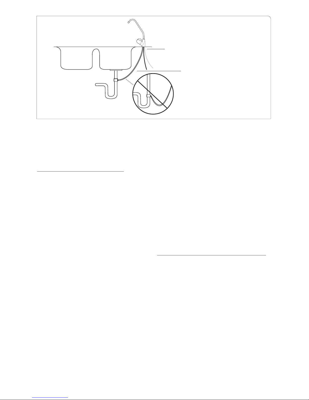
3. 3/8” Black Drain Tube from Faucet: Connect
this tube to the black 3/8” drain clamp. (See D
in Figure 2). Tighten firmly so tube will not pull
out of drain clamp. IMPORTANT: Do not leave
excessive slack in drain tubing. Shorten tubing
so that it flows directly to the drain with no
dips, loops, low spots, or kinks. If not installed
correctly, water will be forced out the side airgap hole of the faucet.
4. Post Filter Connection to Faucet: KR10: Connect the 3/8” blue tube on the front of the
post-filter bowl (labeled out) to the 3/8” pushin adapter fitting on the R/O faucet. KR15:
Connect the 3/8” blue tube on the back of the
post-filter bowl (labeled out) to the 3/8” pushin adapter fitting on the R/O faucet.
5. R/O Tank Connection: KR10: Connect the 3/8”
blue tube on the back of the post-filter bowl
(from the tee fitting) to the push-in ball valve
on top of the R/O storage tank. KR15: Connect
the 3/8” blue tube on the front of the post-filter
bowl (from the tee fitting) to the push-in ball
valve on top of the R/O storage tank.
STEP 7 SYSTEM START-UP PROCEDURES
Turn your sink cold water supply valve to the on
position while leaving the Filter Pac/R/O module and R/O tank ball valves in the off position
(horizontal, which is perpendicular to the valve).
Check for leaks and adjust as necessary.
1. Slowly turn Filter Pac/R/O module ball valve
to the on position (blue valve vertical, which
is in line with the valve). As water enters the
filter bowls and makes its way through the filters to the membrane element you will hear
air escaping through the drain. This is normal.
Open R/O faucet on the sink until the water
starts coming out. (Water flow will only be a
trickle and may take up to 20 minutes before
water starts to come out of the faucet spout on
some units). Shut R/O faucet off and check for
leaks and adjust as necessary.
FIGURE 2
Faucet supply from R/O system
NO DIPS IN LINE
C (Red line connects to R/O drain line)
D

8
| Krystal Pure™ | Reverse Osmosis System Manual
2. Open the tank ball valve by turning handle a ¼
turn toward the tubing. Let tank fill for 4 to 6
hours (if you are changing filters, your tank may
already be full, so you would not need to wait).
Then turn on R/O faucet and drain tank completely, (approx. 5 minutes). Shut R/O faucet
off, allow tank to refill, and drain again in 4 to
6 hours. The R/O system is shipped with a food
grade preservative and must be flushed out prior to use. DO NOT DRINK THE R/O WATER
UNTIL TANK HAS BEEN DRAINED TWICE.
3. Shut R/O faucet off and let system fill again.
R/O water is now ready for use.
IMPORTANT: Check carefully for small leaks every
few hours for the first few days to assure there are
no leaks. It is wise on any R/O system to inspect for
leaks since the system sits unseen underneath your
sink and a small leak may not be detected without close inspection. Check for leaks occasionally
thereafter and make adjustments as necessary
STEP 8 REFRIGERATOR ICE MAKER
HOOK UP
1. If there is not an ice-line from the R/O to the
refrigerator, you may choose to run an ice-line
so that your ice and water dispenser will have
filtered water. If the distance from the refrigerator to the R/O is more than 50 ft., we recommend 3/8” polypropylene or polyethylene
tubing for best results. DO NOT USE COPPER
(Be sure you have the recommended water
pressure to your ice maker according to the
refrigerator manufacturer’s specifications.) 3/8”
tubing, a supplemental storage tank, more R/O
air pressure, or different usage patterns, may be
required to supply adequate pressure!
2. Connect tube (not included) to appropriate refrigerator connection and to a plastic “T” fitting
(not included) spliced into the 3/8” blue tube
between the post filter and faucet. It is recommended to install a ball valve on the tube to the
refrigerator for service and start up purposes.
Keep ball valve off until start up procedures are
completed and R/O tank is completely full after
the second tank draining.
IMPORTANT: Never turn on icemaker before
R/O tank is full of water to avoid damaging refrigerator solenoid. If your refrigerator has a water
dispenser in the door, upon initial start-up you
will need to depress the water supply lever 2 to 3
minutes before the water will dispense.
STEP 9 RECOMMENDED FILTER
SERVICE LIFE
The types of filters listed below vary depending
on R/O system style. The manufacturer provides
very high capacity carbon filters and replacement intervals are based on our filters. Other
filters may not have the same capacity as original factory filters and may not last as long. Water
conditions vary greatly by region and can affect
filter change intervals. For filter change interval
recommendations, follow the guidelines below.
If in doubt, contact the manufacturer.
Sediment Pre-filter: These are the only filter(s)
that you can visually inspect. They are white
when new and will turn dark with dirt and sediment when changing is necessary. A water softener will extend the life of the filter(s). Inspect every 6 months or sooner in bad water conditions.
Carbon Pre-filter: These filters should be
changed at least once a year. Changing these filters is necessary to help insure membrane life and
water quality. Use of high capacity carbon block
filters is recommended. Granular carbon filters
are not recommended because they release excessive carbon fines at initial start-up, which can
reduce the life of the membrane element.
R/O Membrane: The R/O membrane element is
a replaceable component critical for effective reduction of TDS (Total Dissolved Solids). The R/O
membrane should be changed when TDS rejection
rate falls below 75%. The rejection rate should be
tested periodically to insure optimal performance.
The membrane typically lasts 2-5 years depending
on influent water quality and hardness. See performance indicator information listed below.*
Carbon Post-filter/Carbon M.A.P.™ Filter: These
filters need to be changed at least every 12
months to insure quality water. Do not wait until
taste is a problem.
*Performance indicator. The R/O system contains
a replaceable treatment component critical for effective reduction of TDS (Total Dissolved Solids).
The product water shall be tested periodically to
verify that the system is performing properly. Testing can be accomplished by contacting the service
company that installed your R/O system or an authorized dealer. If a service company is not available in your area a water sample may be sent to
AmeriFlow™ for a free TDS test of your R/O water.
Additionally a water quality monitor is available
for purchase from the manufacturer that will allow
the product water to be tested at home.
To send water samples for TDS testing to the manufacturer do the following. Using 2 clean containers put approximately ½ cup of tap water in one

9
container and ½ cup of R/O product water in the
other container. Send both samples to the manufacturer along with your contact information.
To order replacement filters or locate a source
in your area call the factory: AmeriFlow™ Water
Systems Inc. (602) 275-4188.
STEP 10 FILTER CHANGING PROCEDURES
Sediment and Carbon: Turn Filter Pac/R/O mod-
ule ball valve to off position. Turn tank ball valve
off. Turn on R/O faucet to help de-pressurize
system. Unscrew filter bowls by turning counter-clockwise. Remove old filters and discard.
Clean filter bowls if needed in warm, soapy water. Insert new filters into appropriate filter bowls.
Make sure O-ring at top of filter bowl is clean, lubricated and seated properly when tightening. If
changing the post filter, do so now following the
same procedure as the pre-filters. Follow Step 7:
System Start-Up Procedures. Check for leaks and
adjust as necessary.
R/O Membrane: Turn R/O tank and water supply
off. Turn on R/O faucet to help de-pressurize system. Disconnect white tube going into membrane
housing. Unscrew end cap of membrane housing. Have a towel and a bucket handy because
some water will pour out. Pull out old membrane
and clean membrane housing if necessary with
warm, soapy water. Insert new membrane in the
same direction as old membrane. Push firmly up
to properly seat R/O membrane. Replace end cap
and reconnect white tube to membrane housing.
Follow Step 7: System Start-Up Procedures. System should be sanitized each time the membrane
is changed. (See Recommended Sanitizing Procedures). Test TDS (Total Dissolved Solids) rejection rates and be sure the rates are over 75%. A
TDS monitor is optional on some models and included on others. If your unit did not come with
a monitor, you can order one or seek advice from
a local water treatment service company. A new
membrane should perform between 90-98% TDS
removal. Check for leaks and adjust as necessary.
STEP 11 RECOMMENDED SANITIZING
PROCEDURE
The manufacturer recommends having your system professionally sanitized once a year. The best
time to sanitize is when changing all the filters
and/or when changing the membrane.
1. Drain all water from R/O tank by turning on
R/O faucet until water stops flowing. Follow
Filter Changing Procedures (assuring ball
valve on tank and Filter Pac/R/O module
are in off position). Remove old pre-filters
and membrane from housings. Remove the
post-filter from the filter bowl canister.
2. Carefully put 2 capfuls of household bleach
into the empty filter bowl canisters. Re-install
filter bowls without filters. CAUTION: Be careful not to splash bleach on hands or surfaces.
3. Turn water supply on (open ball valve on
tank and R/O module) and let system fill for 4
minutes with tap water. Shut system off. Turn
R/O faucet on until water comes out and then
shut it off.
4. Let entire system sit for about 30 minutes
to sanitize. Then turn on R/O faucet and let
system drain until empty. Turn off water supply valves and empty water in filter bowls.
Re-install filter bowls. Turn the water supply
on again. Turn off faucet and let system refill with tap water as before. Drain again. Install new filters following the Step 10: Filter
Change Procedures. Follow Step 7: System
Start-Up Procedures.
STEP 12 SERVICE AND MAINTENANCE
RECOMMENDATIONS
All Reverse Osmosis systems require periodic
maintenance to insure the continuation of wa-
FILTER REPLACEMENT LIST
Part Numbers
R/O Model PRE SEDIMENT PRE CARBON MEMBRANE M.A.P.™ CARBON POST CARBON
KR5 N/A CB05 #135-1210-1 TFC-24 #138-
124-1
N/A CB #135-1210-2
KR10 P1 #136-1110-1 CB05 #135-1210-1 TFC-24 #138-
124-1
N/A CB #135-1210-2
KR15
N/A
CB05 #135-1210-1 TFC-24 #138-
124-1
CB-A #135-1210-2 CB #135-1210-2
Replacement
Frequency
6mo. - 1yr.
1 yr. 2-5 yrs. 1 yr. 1 yr.

10
| Krystal Pure™ | Reverse Osmosis System Manual
ter quality. Test TDS rejection rates at least every 6 months. Changing filters is important for
continuous good water quality. Filters need to
be replaced at recommended intervals as old filters may retain a considerable amount of debris
and contaminants. Failure to change filters, use
of lower quality filters, or improper sanitization
can dramatically reduce membrane life and water quality. DO NOT WAIT UNTIL YOUR WA-
TER TASTES BAD TO REPLACE YOUR FILTERS.
Remember most contaminants do not have a foul
taste except in extreme quantities. Testing the
check valve, flow restrictor, incoming water pressure, water hardness, and TDS levels periodically
are important to help extend membrane life and
overall water quality. Your local water professional can easily perform these tests. Failure to follow
proper maintenance instructions, use of filters
or parts other than those recommended by the
manufacturer, or use of an unauthorized service
agent may void your warranty.
REPLACEMENT PARTS LIST: KR5 • KR10 • KR15
Qty. Part No. Description Qty. Part No. Description
1 103-0504 Easy Tap Adapter 1 805-70-06 Fitting Union 3/8” JG Tee
1 419-1404-1 ¼” JG 90 Ball Valve 1 805-S10-06 Fitting ¼” mpt × 3/8” stem
1
805-S10-04
Fitting ¼” mpt × ¼” stem 2 805-40-06 Fitting ¼” mpt × 3/8” JG
Elbow
2
804-11-04
¼” Hex Nipple 1 125-124 R/O Faucet, Specify Color
1
419-1406
3/8” JG 90 Ball Valve, Storage
Tank
1 805-25-04 Faucet Adapter 3/8” ×
7/16” fpt
3
805-40-02
Fitting ¼” mpt × ¼” JG Elbow 1 805-15-04 ¼” Union JG
1
123-541
Water Conservation Shut-Off
Valve
1 124-462 Drain Saddle Clamp
1
128 - 00
R/O Membrane Housing 3 127-1101 Filter Bowl Canister
1
128 -R
O-ring, Membrane Housing 3 127-1R O-ring, Filter Bowl canister
2
805-40-04
Fitting 1/8” mpt × ¼” JG Elbow 6 805-LC-06 3/8” Locking Clip JG
1
121-1604-1
Check Valve Fitting 1/8” mpt ×
¼” JG Elbow
12 805-LC- 04 ¼” Locking Clip JG
1
129 -260
Flow Restrictor, 260 mL 2 122-321 Clips, Membrane
1
110-03181
3.2 Gallon Storage Tank 1 120 -131 Bracket
1
805-40042
Fitting 3/8” stem × ¼” JG
Elbow
TROUBLE SHOOTING GUIDE
PROBLEM CAUSE SOLUTION
Cloudy ice
cubes or milky
colored water.
Bad membrane. Replace Membrane and sanitize when below 75% rejec-
tion.
Water supply. High oxygen content.
Refrigerator. Some refrigerators freeze differently, leaving the ice cube
looking cloudy. Let cube dissolve in glass of water. If just
air, will float to surface and dissipate.
System is still new. This is normal and should clear up in two weeks
 Loading...